JP5170913B2 - Polarizing film laminating apparatus and liquid crystal display manufacturing system having the same - Google Patents
Polarizing film laminating apparatus and liquid crystal display manufacturing system having the same Download PDFInfo
- Publication number
- JP5170913B2 JP5170913B2 JP2011086997A JP2011086997A JP5170913B2 JP 5170913 B2 JP5170913 B2 JP 5170913B2 JP 2011086997 A JP2011086997 A JP 2011086997A JP 2011086997 A JP2011086997 A JP 2011086997A JP 5170913 B2 JP5170913 B2 JP 5170913B2
- Authority
- JP
- Japan
- Prior art keywords
- substrate
- polarizing film
- transport mechanism
- reversing
- unit
- Prior art date
- Legal status (The legal status is an assumption and is not a legal conclusion. Google has not performed a legal analysis and makes no representation as to the accuracy of the status listed.)
- Expired - Fee Related
Links
Images


Classifications
-
- G—PHYSICS
- G02—OPTICS
- G02B—OPTICAL ELEMENTS, SYSTEMS OR APPARATUS
- G02B5/00—Optical elements other than lenses
- G02B5/30—Polarising elements
- G02B5/3025—Polarisers, i.e. arrangements capable of producing a definite output polarisation state from an unpolarised input state
- G02B5/3033—Polarisers, i.e. arrangements capable of producing a definite output polarisation state from an unpolarised input state in the form of a thin sheet or foil, e.g. Polaroid
-
- G—PHYSICS
- G02—OPTICS
- G02F—OPTICAL DEVICES OR ARRANGEMENTS FOR THE CONTROL OF LIGHT BY MODIFICATION OF THE OPTICAL PROPERTIES OF THE MEDIA OF THE ELEMENTS INVOLVED THEREIN; NON-LINEAR OPTICS; FREQUENCY-CHANGING OF LIGHT; OPTICAL LOGIC ELEMENTS; OPTICAL ANALOGUE/DIGITAL CONVERTERS
- G02F1/00—Devices or arrangements for the control of the intensity, colour, phase, polarisation or direction of light arriving from an independent light source, e.g. switching, gating or modulating; Non-linear optics
- G02F1/01—Devices or arrangements for the control of the intensity, colour, phase, polarisation or direction of light arriving from an independent light source, e.g. switching, gating or modulating; Non-linear optics for the control of the intensity, phase, polarisation or colour
- G02F1/13—Devices or arrangements for the control of the intensity, colour, phase, polarisation or direction of light arriving from an independent light source, e.g. switching, gating or modulating; Non-linear optics for the control of the intensity, phase, polarisation or colour based on liquid crystals, e.g. single liquid crystal display cells
- G02F1/1303—Apparatus specially adapted to the manufacture of LCDs
-
- G—PHYSICS
- G02—OPTICS
- G02F—OPTICAL DEVICES OR ARRANGEMENTS FOR THE CONTROL OF LIGHT BY MODIFICATION OF THE OPTICAL PROPERTIES OF THE MEDIA OF THE ELEMENTS INVOLVED THEREIN; NON-LINEAR OPTICS; FREQUENCY-CHANGING OF LIGHT; OPTICAL LOGIC ELEMENTS; OPTICAL ANALOGUE/DIGITAL CONVERTERS
- G02F1/00—Devices or arrangements for the control of the intensity, colour, phase, polarisation or direction of light arriving from an independent light source, e.g. switching, gating or modulating; Non-linear optics
- G02F1/01—Devices or arrangements for the control of the intensity, colour, phase, polarisation or direction of light arriving from an independent light source, e.g. switching, gating or modulating; Non-linear optics for the control of the intensity, phase, polarisation or colour
- G02F1/13—Devices or arrangements for the control of the intensity, colour, phase, polarisation or direction of light arriving from an independent light source, e.g. switching, gating or modulating; Non-linear optics for the control of the intensity, phase, polarisation or colour based on liquid crystals, e.g. single liquid crystal display cells
- G02F1/133—Constructional arrangements; Operation of liquid crystal cells; Circuit arrangements
- G02F1/1333—Constructional arrangements; Manufacturing methods
- G02F1/1335—Structural association of cells with optical devices, e.g. polarisers or reflectors
- G02F1/133528—Polarisers
Landscapes
- Physics & Mathematics (AREA)
- Nonlinear Science (AREA)
- General Physics & Mathematics (AREA)
- Optics & Photonics (AREA)
- Chemical & Material Sciences (AREA)
- Crystallography & Structural Chemistry (AREA)
- Engineering & Computer Science (AREA)
- Manufacturing & Machinery (AREA)
- Liquid Crystal (AREA)
- Polarising Elements (AREA)
- Mathematical Physics (AREA)
- Devices For Indicating Variable Information By Combining Individual Elements (AREA)
Description
本発明は、偏光フィルムの貼合装置およびこれを備える液晶表示装置の製造システムに関するものである。 The present invention relates to a polarizing film laminating apparatus and a liquid crystal display manufacturing system including the same.
従来、液晶表示装置が広く製造されている。液晶表示装置に用いられる基板(液晶パネル)には、光の透過または遮断を制御するために、偏光フィルムが貼合されることが通常である。偏光フィルムはその吸収軸が直交するように貼合されている。 Conventionally, liquid crystal display devices have been widely manufactured. In general, a polarizing film is bonded to a substrate (liquid crystal panel) used in a liquid crystal display device in order to control transmission or blocking of light. The polarizing film is bonded so that the absorption axes thereof are orthogonal.
基板に偏光フィルムを貼合する方法としては、偏光フィルムを基板に応じたサイズにカットした後に貼合する所謂 chip to panel方式が挙げられる。しかしながら、この方式では、基板に対して、一枚ずつ偏光フィルムを貼合するため、生産効率が低いという欠点がある。一方、他の方式として、偏光フィルムをコンベアーロールに供給し、連続的に基板に貼合する所謂 roll to panel方式が挙げられる。当該方法によれば、高い生産効率にて貼合が可能となる。 As a method of bonding the polarizing film to the substrate, a so-called chip to panel method in which the polarizing film is bonded to the substrate after being cut into a size corresponding to the substrate can be mentioned. However, this method has a disadvantage that the production efficiency is low because the polarizing films are bonded to the substrate one by one. On the other hand, as another method, there is a so-called roll to panel method in which a polarizing film is supplied to a conveyor roll and continuously bonded to a substrate. According to this method, bonding can be performed with high production efficiency.
roll to panel 方式の例として、特許文献1に光学表示装置の製造システムが開示されている。上記製造システムは、基板の上面に光学フィルム(偏光フィルム)を貼合した後に、基板を旋回させ、下面から偏光フィルムを貼合するものである。
As an example of the roll to panel method,
しかしながら、上記従来の装置では、以下の問題がある。 However, the conventional apparatus has the following problems.
まず、基板に対して偏光フィルムを貼合する場合、埃などの異物が貼合面へ混入することを回避するため、クリーンルームにて作業がなされるのが通常である。そして、クリーンルームでは、空気の整流がなされている。基板に対してダウンフローにて整流がなされた状態にて偏光フィルムの貼合がなされることが、異物による歩留低下を抑制するために必要だからである。 First, when a polarizing film is bonded to a substrate, work is usually performed in a clean room in order to prevent foreign matters such as dust from entering the bonding surface. In the clean room, air is rectified. This is because it is necessary to bond the polarizing film in a state in which rectification is performed on the substrate in a downflow in order to suppress the yield reduction due to the foreign matter.
この点に関して、特許文献1の製造システムは、基板に対して、上面および下面から偏光フィルムを貼合する構成となっている。しかし、偏光フィルムの上面から貼合を行う場合、気流(ダウンフロー)が偏光フィルムによって妨げられ、基板への整流環境が悪化してしまうというデメリット挙げられる。偏光フィルムの上面から貼合を行う場合の例として、図10(a)および図10(b)に上貼り型の製造システムにおける気流の速度ベクトルを示す。図10における、領域Aは、偏光フィルムを巻出す巻出部等が設置される領域であり、領域Bは主に偏光フィルムが通過する領域、および、領域Cは、偏光フィルムから除去された剥離フィルムを巻き取る巻取部等が設置される領域である。
In this regard, the manufacturing system of
また、HEPA(High Efficiency Particulate Air )フィルター40からはクリーンエアーが供給される。なお、図10(a)では、クリーンエアーが通過可能なグレーチング41が設置されているためグレーチング41を介して気流が垂直方向に移動することが可能である。一方、図10(b)では、グレーチング41が設置されていないため、気流は図10(b)最下部の床に接触した後、床に沿って移動することとなる。
Clean air is supplied from a HEPA (High Efficiency Particulate Air)
図10(a)・(b)には、領域A〜Cが2F(2階)部分に配置されており、HEPAフィルター40からのクリーンエアーが偏光フィルムによって妨げられる。したがって、2F部分を通過する基板に対して垂直方向に向う気流が生じ難い。これに対して、水平方向の気流ベクトルは大きな(ベクトルの密度が濃い)状態となっている。すなわち、整流環境が悪化した状態であるといえる。
10A and 10B, the areas A to C are arranged in the 2F (second floor) portion, and the clean air from the
本発明は、上記従来の問題点に鑑みなされたものであって、その目的は、整流環境を妨げることのない偏光フィルムの貼合装置およびこれを備える液晶表示装置の製造システムを提供することにある。 This invention is made | formed in view of the said conventional problem, Comprising: The objective is to provide the manufacturing system of a polarizing film bonding apparatus and a liquid crystal display device provided with the same which do not disturb a rectification environment. is there.
請求項1に記載の本発明(第1発明)の偏光フィルムの貼合装置は、上記課題を解決するために、長方形の基板を長辺または短辺が搬送方向に沿った状態にて搬送する第1基板搬送機構と、上記第1基板搬送機構における上記基板の下面に偏光フィルムを貼合する第1貼合部と、上記第1基板搬送機構にて搬送された上記基板を反転させて第2基板搬送機構に配置する反転機構と、上記基板を短辺または長辺が搬送方向に沿った状態にて搬送する第2基板搬送機構と、上記第2基板搬送機構における上記基板の下面に偏光フィルムを貼合する第2貼合部とを含む偏光フィルム貼合装置であって、上記第1基板搬送機構と第2基板搬送機構とは同一方向に向かって配置されており、上記反転機構は上記基板を吸着する吸着部と、上記吸着部に連結されており、基板を反転させる基板反転部とを備えており、上記基板反転部は、第1基板搬送機構における基板を、(1)曲線を描くように、(2)反転させながら、(3)第1基板搬送機構の搬送方向に沿った長辺または短辺が搬送方向に対して直交する方向に沿うように、第2基板搬送機構に配置することを備える
ものである。
In order to solve the above-mentioned problems, the polarizing film laminating device of the present invention (first invention) according to claim 1 transports a rectangular substrate with the long side or the short side along the transport direction. A first substrate transport mechanism, a first bonding unit for bonding a polarizing film to the lower surface of the substrate in the first substrate transport mechanism, and the substrate transported by the first substrate transport mechanism are reversed to A reversing mechanism disposed in the two-substrate transport mechanism, a second substrate transport mechanism that transports the substrate with a short side or a long side along the transport direction, and polarization on the lower surface of the substrate in the second substrate transport mechanism It is a polarizing film bonding apparatus containing the 2nd bonding part which bonds a film, Comprising: The said 1st board | substrate conveyance mechanism and a 2nd board | substrate conveyance mechanism are arrange | positioned toward the same direction, The said inversion mechanism is A suction part for sucking the substrate, and a suction part connected to the suction part. And a substrate reversing unit for reversing the substrate, wherein the substrate reversing unit is (1) while reversing the substrate in the first substrate transport mechanism (1) so as to draw a curve (3) ) It is arranged to be arranged on the second substrate transport mechanism so that the long side or the short side along the transport direction of the first substrate transport mechanism is along the direction orthogonal to the transport direction.
上記の第1発明によれば、第1貼合部によって基板の下面に偏光フィルムを貼合し、反転機構によって、第1基板搬送機構における基板を、反転させ、第1基板搬送機構の搬送方向に沿った長辺または短辺が搬送方向に対して直交する方向に沿う状態にて、第2基板搬送機構に配置することができ、その後、第2貼合部によって基板の下面に偏光フィルムを貼合することができる。すなわち、基板の両面に対して、下面から偏光フィルムを貼合することができるため、整流環境を妨げることがない。また、反転機構の動作は1つの動作であるため、タクトタイムが短い。したがって、タクトタイムの短い貼合をも実現できる。さらに、上記第1基板搬送機構と第2基板搬送機構とが同一方向に向かって配置されている。すなわち、L字型形状などの複雑な構造を有していない。したがって、本発明に係る貼合装置は、設置が非常に簡便であり、面積効率に優れる。 According to said 1st invention, a polarizing film is bonded to the lower surface of a board | substrate by the 1st bonding part, the board | substrate in a 1st board | substrate conveyance mechanism is reversed by the inversion mechanism, and the conveyance direction of a 1st board | substrate conveyance mechanism The long side or the short side along the direction along the direction orthogonal to the transport direction can be arranged in the second substrate transport mechanism, and then the polarizing film is applied to the lower surface of the substrate by the second bonding unit. Can be pasted. That is, since a polarizing film can be bonded from the lower surface to both surfaces of the substrate, the rectifying environment is not hindered. Moreover, since the operation of the reversing mechanism is one operation, the tact time is short. Therefore, it is possible to realize bonding with a short tact time. Further, the first substrate transport mechanism and the second substrate transport mechanism are arranged in the same direction. That is, it does not have a complicated structure such as an L shape. Therefore, the bonding apparatus according to the present invention is very simple to install and is excellent in area efficiency.
請求項2に記載の本発明(第2発明)の偏光フィルムの貼合装置は、
長方形の基板を長辺または短辺が搬送方向に沿った状態にて搬送する第1基板搬送機構と、
上記第1基板搬送機構における上記基板の下面に偏光フィルムを貼合する第1貼合部と、
上記第1基板搬送機構にて搬送された上記基板を支持する基板支持部を備えた基板支持装置と、
上記基板支持部に連結して該基板支持部に支持された基板を反転させて配置する基板反転部を備えた反転機構と、
上記反転機構によって反転させるとともに短辺または長辺が搬送方向に沿った状態にて配置された上記基板を搬送する第2基板搬送機構と、
上記第2基板搬送機構における上記基板の下面に偏光フィルムを貼合する第2貼合部とを含む偏光フィルム貼合装置であって、
上記第1基板搬送機構と第2基板搬送機構とは同一方向に向かって配置されており、
上記反転機構は、上記基板の表面が裏面になるように基板反転部を反転させる反転軸および上記第1基板搬送機構において搬送される上記基板の配置方向から上記第2基板搬送機構において搬送される上記基板の配置方向に配置変更部によって変更される配置変更軸回りに一定角度範囲で回転させることにより、上記第1基板搬送機構において搬送された上記基板を円弧軌跡を描いて反転させるとともに、上記第2基板搬送機構における基板の搬送方向に沿うように配置を変更して、上記第2基板搬送機構に対して配置されるように構成されている
ものである。
The bonding apparatus for the polarizing film of the present invention (second invention) according to claim 2 is:
A first substrate transport mechanism for transporting a rectangular substrate with a long side or a short side along the transport direction;
A first bonding unit for bonding a polarizing film to the lower surface of the substrate in the first substrate transport mechanism;
A substrate support device comprising a substrate support unit for supporting the substrate transported by the first substrate transport mechanism;
A reversing mechanism provided with a substrate reversing unit that is connected to the substrate supporting unit and arranged to reverse the substrate supported by the substrate supporting unit;
A second substrate transport mechanism that transports the substrate that is reversed by the reversing mechanism and that has the short side or the long side disposed along the transport direction;
A polarizing film laminating apparatus including a second laminating unit for laminating a polarizing film on the lower surface of the substrate in the second substrate transport mechanism,
The first substrate transport mechanism and the second substrate transport mechanism are arranged in the same direction,
The reversing mechanism is transported by the second substrate transport mechanism from a reversing axis that reverses the substrate reversing unit so that the front surface of the substrate is the back surface and the arrangement direction of the substrate transported by the first substrate transport mechanism. The substrate transported in the first substrate transport mechanism is reversed by drawing an arc locus by rotating the substrate in the layout direction by a fixed angle range around the placement change axis changed by the placement changing unit in the placement direction of the substrate. The arrangement is changed so as to be along the substrate carrying direction in the second substrate carrying mechanism, and the second substrate carrying mechanism is arranged with respect to the second substrate carrying mechanism.
請求項3に記載の本発明(第3発明)の偏光フィルムの貼合装置は、
第2発明において、
前記反転機構は、前記基板反転部が前記配置変更部に回転可能に配設された前記反転軸を備える反転軸部に連結して、回転駆動源によってそれぞれ回転駆動されるように構成されている
ものである。
The polarizing film laminating device of the present invention (third invention) according to claim 3 is:
In the second invention,
The reversing mechanism is configured such that the substrate reversing unit is connected to a reversing shaft unit including the reversing shaft rotatably disposed on the arrangement changing unit, and is rotated by a rotation driving source. Is.
請求項4に記載の本発明(第4発明)の偏光フィルムの貼合装置は、
第2発明において、
前記反転機構は、前記配置変更部が前記反転軸を備える反転軸部に連結した前記基板反転部に相対回転可能に配設され、回転駆動源によってそれぞれ回転駆動されるように構成されている
ものである。
The bonding apparatus for the polarizing film of the present invention (fourth invention) according to claim 4 is:
In the second invention,
The reversing mechanism is configured such that the arrangement changing unit is disposed so as to be relatively rotatable on the substrate reversing unit connected to the reversing shaft unit including the reversing shaft, and is rotated by a rotation driving source. It is.
請求項5に記載の本発明(第5発明)の偏光フィルムの貼合装置は、
第2発明ないし第4発明のいずれかにおいて、
上記基板支持装置の上記基板支持部が、上記第1基板搬送機構にて搬送された上記基板の両面を挟着して支持する複数の支持部材によって構成されている
ものである。
The polarizing film laminating device of the present invention (the fifth invention) according to
In any one of the second invention to the fourth invention,
The substrate support part of the substrate support device is constituted by a plurality of support members that sandwich and support both surfaces of the substrate transported by the first substrate transport mechanism.
請求項6に記載の本発明(第6発明)の偏光フィルムの貼合装置は、
第2発明ないし第4発明のいずれかにおいて、
上記基板支持装置の上記基板支持部が、上記第1基板搬送機構にて搬送された上記基板の表面を吸着する吸着部を備えた吸着部材によって構成されている
ものである。
The pasting device for the polarizing film of the present invention (sixth invention) according to
In any one of the second invention to the fourth invention,
The substrate support part of the substrate support device is configured by an adsorption member including an adsorption part that adsorbs the surface of the substrate conveyed by the first substrate conveyance mechanism.
請求項7に記載の本発明(第7発明)の偏光フィルムの貼合装置は、
第3発明または第4発明において、
上記基板支持装置が、上記基板の反転動作を行う基板反転部に連結した部材に配設され、上記第1基板搬送機構および第2基板搬送機構の端部に進入する第1の支持部材と第2の支持部材との相対的移動によって、上記第1の支持部材と第2の支持部材との間に上記第1基板搬送機構から搬送された上記基板を、挟着することによって支持するとともに、上記第1の支持部材と第2の支持部材との相対的移動によって、上記基板反転部によって反転された上記第1の支持部材と第2の支持部材との間に挟着されることによって支持された上記基板を、挟着による支持を解除して、上記第2基板搬送機構の端部に載置するように構成されている
ものである。
The bonding apparatus for the polarizing film of the present invention (seventh invention) according to claim 7 is:
In the third invention or the fourth invention,
The substrate supporting device is disposed on a member connected to a substrate reversing unit that performs the reversing operation of the substrate, and a first supporting member and a first supporting member that enter the end portions of the first substrate transporting mechanism and the second substrate transporting mechanism. And by supporting the substrate transported from the first substrate transport mechanism between the first support member and the second support member by sandwiching the substrate by relative movement with the second support member, Supported by being sandwiched between the first support member and the second support member reversed by the substrate reversing part by the relative movement of the first support member and the second support member. The above-described substrate is released from the support by sandwiching and is placed on the end portion of the second substrate transport mechanism.
請求項8に記載の本発明(第8発明)の偏光フィルムの貼合装置は、
第3発明または第4発明において、
上記第1基板搬送機構の端部が、幅方向に複数の部分に分割され、隣合う部分の間に上記第1および第2の支持部材を構成する第1および第2の櫛状部材の複数の突出部が進入する複数の間隙が形成されているとともに、上記第2基板搬送機構の端部が、搬送方向に複数の部分に分割され、隣合う部分の間に反転した上記第1および第2の支持部材を構成する上記第1および第2の櫛状部材の複数の突出部が進入する複数の間隙が形成されている
ものである。
The polarizing film laminating device of the present invention (eighth invention) according to claim 8 is:
In the third invention or the fourth invention,
The end portions of the first substrate transport mechanism are divided into a plurality of portions in the width direction, and a plurality of first and second comb-like members that constitute the first and second support members between adjacent portions. A plurality of gaps into which the protrusions of the first substrate and the second substrate transport mechanism enter, and an end portion of the second substrate transport mechanism is divided into a plurality of portions in the transport direction and inverted between adjacent portions. A plurality of gaps into which a plurality of protrusions of the first and second comb-shaped members constituting the second support member enter are formed.
請求項9に記載の本発明(第9発明)の偏光フィルムの貼合装置は、
第8発明において、
上記第1および第2の支持部材を構成する複数の突出部を備えた第1および第2の櫛状部材が、一部を支点として一定角度範囲において揺動するように構成されている
ものである。
The polarizing film laminating apparatus of the present invention (the ninth invention) according to claim 9 is:
In the eighth invention,
The first and second comb-like members having a plurality of protrusions constituting the first and second support members are configured to swing within a certain angle range with a part as a fulcrum. is there.
請求項10に記載の本発明(第10発明)の偏光フィルムの貼合装置は、
第9発明において、
上記第1および第2の支持部材を構成する複数の突出部を備えた上記第1および第2の櫛状部材が、揺動駆動機構によって揺動駆動されるように構成されている
ものである。
A polarizing film laminating apparatus of the present invention (tenth invention) according to claim 10 is:
In the ninth invention,
The first and second comb-like members having a plurality of protrusions constituting the first and second support members are configured to be driven to swing by a swing drive mechanism. .
請求項11に記載の本発明(第11発明)の偏光フィルムの貼合装置は、
第10発明において、
上記揺動駆動機構は、上記第1の支持部材を構成する複数の突出部を備えた上記第1の櫛状部材を揺動駆動する第1の揺動駆動機構と、第2の支持部材を構成する複数の突出部を備えた上記第2の櫛状部材を揺動駆動される第2の揺動駆動機構とから成る
ものである。
The polarizing film laminating device of the present invention (11th invention) according to
In the tenth invention,
The swing drive mechanism includes a first swing drive mechanism that swings and drives the first comb-like member having a plurality of protrusions that constitute the first support member, and a second support member. It comprises a second swing drive mechanism that swings and drives the second comb-like member having a plurality of projecting portions.
請求項12に記載の本発明(第12発明)の偏光フィルムの貼合装置は、
第8発明において、
上記第1および第2の支持部材を構成する複数の突出部を備えた上記第1および第2の櫛状部材が、一方向において相対的に接近または離隔して対向間隔が変化するように往復動可能に構成されている
ものである。
The polarizing film laminating device of the present invention (the twelfth invention) according to claim 12
In the eighth invention,
The first and second comb-like members having a plurality of projecting portions constituting the first and second support members are reciprocated so that the facing distance is changed by relatively approaching or separating in one direction. It is configured to be movable.
請求項13に記載の本発明(第13発明)の偏光フィルムの貼合装置は、
第12発明において、
上記第1および第2の支持部材を構成する複数の突出部を備えた上記第1および第2の櫛状部材が、直線的駆動機構によって駆動され、往復動するように構成されている
ものである。
The polarizing film laminating apparatus of the present invention (the thirteenth aspect) according to
In the twelfth invention,
The first and second comb-like members having a plurality of protrusions constituting the first and second support members are configured to be driven by a linear drive mechanism and reciprocate. is there.
また、請求項14に記載の本発明(第14発明)の偏光フィルムの貼合装置では、上記第1基板搬送機構および第2基板搬送機構が一直線上に配置されており、第1基板搬送機構における第2基板搬送機構側の端部において、第1基板搬送機構の搬送方向に対して水平な両方向に沿って、基板載置部および上記反転機構が2対ずつ備えられ、上記端部には、上記端部から上記基板載置部へ基板を搬送する搬送手段が備えられており、上記反転機構は上記基板載置部のそれぞれに搬送された基板を反転させて第2基板搬送機構に配置することが好ましい。 In the polarizing film bonding apparatus according to the fourteenth aspect of the present invention (fourteenth aspect), the first substrate transport mechanism and the second substrate transport mechanism are arranged in a straight line, and the first substrate transport mechanism In the end portion on the second substrate transport mechanism side, two pairs of substrate placement portions and the above reversing mechanisms are provided along both directions parallel to the transport direction of the first substrate transport mechanism. A transfer means for transferring the substrate from the end portion to the substrate mounting portion, and the reversing mechanism reverses the substrate transferred to each of the substrate mounting portions and arranges it on the second substrate transfer mechanism. It is preferable to do.
上記構成によれば、反転機構が2つ備えられているため、基板を単位時間当り2倍処理することができる。これにより、単位時間当たり多くの基板の反転が可能なため、タクトタイムが短縮される。さらに、第1基板搬送機構および第2基板搬送機構が一直線上に配置されているため、より面積効率に優れた構造の貼合装置を提供できる。 According to the above configuration, since two reversing mechanisms are provided, the substrate can be processed twice per unit time. Thereby, since many substrates can be reversed per unit time, the tact time is shortened. Furthermore, since the 1st board | substrate conveyance mechanism and the 2nd board | substrate conveyance mechanism are arrange | positioned on the straight line, the bonding apparatus of the structure excellent in area efficiency can be provided.
また、請求項15に記載の本発明(第15発明)の偏光フィルムの貼合装置では、偏光フィルムを搬送する第1フィルム搬送機構および第2フィルム搬送機構が備えられており、上記第1フィルム搬送機構には、剥離フィルムに保護された偏光フィルムを巻出す複数の巻出部と、偏光フィルムを切断する切断部と、偏光フィルムから剥離フィルムを除去する除去部と、除去された上記剥離フィルムを巻取る複数の巻取部とが備えられており、上記第2フィルム搬送機構には、剥離フィルムに保護された偏光フィルムを巻出す複数の巻出部と、偏光フィルムを切断する切断部と、偏光フィルムから剥離フィルムを除去する除去部と、除去された上記剥離フィルムを巻取る複数の巻取部とが備えられており、上記第1基板搬送機構および第2基板搬送機構は上記第1フィルム搬送機構および第2フィルム搬送機構の上部に備えられており、上記剥離フィルムが除去された偏光フィルムを基板に貼合する上記第1貼合部が上記第1フィルム搬送機構と第1基板搬送機構との間に、上記剥離フィルムが除去された偏光フィルムを基板に貼合する第2貼合部が上記第2フィルム搬送機構と第2基板搬送機構との間にそれぞれ備えられていることが好ましい。 Moreover, in the polarizing film bonding apparatus of the present invention (fifteenth invention) according to claim 15, a first film transport mechanism and a second film transport mechanism for transporting the polarizing film are provided, and the first film is provided. The transport mechanism includes a plurality of unwinding portions for unwinding the polarizing film protected by the release film, a cutting portion for cutting the polarizing film, a removal portion for removing the release film from the polarizing film, and the removed release film. The second film transport mechanism includes a plurality of unwinding sections for unwinding the polarizing film protected by the release film, and a cutting section for cutting the polarizing film. A removing unit that removes the release film from the polarizing film, and a plurality of winding units that wind up the removed release film, and the first substrate transport mechanism and the second substrate. The feeding mechanism is provided above the first film transport mechanism and the second film transport mechanism, and the first bonding section that bonds the polarizing film from which the release film has been removed to the substrate is the first film transport. Between the mechanism and the first substrate transport mechanism, each of the second bonding parts for bonding the polarizing film from which the release film has been removed to the substrate is between the second film transport mechanism and the second substrate transport mechanism. It is preferable that it is provided.
これにより、巻出部および巻取部が複数備えられているため、一方の巻出部における偏光フィルムの原反の残量が少なくなった場合、その原反に他方の巻出部に備えられた原反を連結させることが可能である。その結果、偏光フィルムの巻出しを停止させることなく、作業を続行することができ、生産効率を高めることができる。 Thereby, since the unwinding part and the winding part are provided in plural, when the remaining amount of the original film of the polarizing film in one unwinding part decreases, the other unwinding part is provided in the original film. It is possible to connect raw materials. As a result, the operation can be continued without stopping the unwinding of the polarizing film, and the production efficiency can be increased.
また、請求項16に記載の本発明(第16発明)の偏光フィルムの貼合装置では、上記第1貼合部によって基板の下面に偏光フィルムを貼合する前に、基板を洗浄する洗浄部を備え、上記第1基板搬送機構は、基板の短辺が搬送方向に沿った状態にて基板を搬送することが好ましい。 Moreover, in the polarizing film bonding apparatus according to the sixteenth aspect of the present invention (the sixteenth aspect), the cleaning unit for cleaning the substrate before the polarizing film is bonded to the lower surface of the substrate by the first bonding unit. The first substrate transport mechanism preferably transports the substrate with the short side of the substrate along the transport direction.
これにより、基板の搬送方向に対して基板の長辺が直交する状態にて、洗浄部による基板の洗浄を行うことができる。すなわち、搬送方向に沿った基板の距離を小さくすることができるため、洗浄に必要なタクトタイムをより短縮することができる。その結果、さらに生産効率に優れた偏光フィルムの貼合装置を提供することができる。 Accordingly, the substrate can be cleaned by the cleaning unit in a state where the long sides of the substrate are orthogonal to the substrate transport direction. That is, since the distance of the substrate along the transport direction can be reduced, the tact time required for cleaning can be further shortened. As a result, it is possible to provide a polarizing film laminating apparatus that is further excellent in production efficiency.
また、請求項17に記載の本発明(第17発明)の偏光フィルムの貼合装置では、上記第1フィルム搬送機構および上記第2フィルム搬送機構には、第1巻出部から巻出された偏光フィルムに付された欠点表示を検出する欠点検出部と、上記欠点表示を判別して、上記基板の搬送を停止させる貼合回避部と、基板との貼合が回避された偏光フィルムを回収する回収部とを有することが好ましい。 Further, in the polarizing film laminating device of the present invention (17th invention) according to claim 17, the first film transport mechanism and the second film transport mechanism are unwound from the first unwinding section. Collects a defect detection unit that detects a defect display attached to the polarizing film, a bonding avoidance unit that discriminates the defect display and stops the conveyance of the substrate, and a polarizing film in which bonding with the substrate is avoided. It is preferable to have a recovery unit.
上記欠点検出部、貼合回避部および回収部によれば、欠点を有する偏光フィルムと基板との貼合を回避できるため、歩留まりを高めることができる。 According to the above-mentioned fault detection part, pasting avoidance part, and recovery part, since a pasting with a polarizing film and a substrate which has a fault can be avoided, a yield can be raised.
請求項18に記載の本発明(第18発明)の液晶表示装置の製造システムは、上記偏光フィルムの貼合装置と、上記第2貼合部によって偏光フィルムの貼合がなされた基板における貼りずれを検査する貼りずれ検査装置を備えるものである。 The manufacturing system of the liquid crystal display device according to the eighteenth aspect of the present invention (18th invention) includes a bonding displacement between the polarizing film bonding apparatus and the substrate on which the polarizing film is bonded by the second bonding portion. A misalignment inspection apparatus for inspecting the film is provided.
これにより、偏光フィルムを貼合した基板に生じた貼りずれを検査することが可能である。 Thereby, it is possible to inspect the sticking deviation which arose on the board | substrate which bonded the polarizing film.
また、請求項19に記載の本発明(第19発明)の液晶表示装置の製造システムでは、上記貼りずれ検査装置による検査結果に基づき貼りずれの有無を判定し、当該判定結果に基づき、偏光フィルムが貼合された基板の仕分けを行う仕分け搬送装置を備えることが好ましい。 In the manufacturing system for a liquid crystal display device according to the nineteenth aspect of the present invention, the presence / absence of sticking deviation is determined based on the inspection result by the sticking deviation inspection apparatus, and the polarizing film is determined based on the determination result. It is preferable to provide a sorting / conveying device for sorting the substrates to which the is bonded.
これにより、偏光フィルムが貼合された基板に貼りずれが生じている場合、速やかに不良品の仕分けを行うことができ、タクトタイムを短縮することが可能である。 Thereby, when the sticking shift | offset | difference has arisen in the board | substrate with which the polarizing film was bonded, it can classify | categorize a defective product quickly and can shorten a tact time.
また、請求項20に記載の本発明(第20発明)の液晶表示装置の製造システムでは、偏光フィルムの貼合装置と、上記貼合装置における第2貼合部によって偏光フィルムの貼合がなされた基板における異物を検査する貼合異物自動検査装置とを備えることが好ましい。 Moreover, in the manufacturing system of the liquid crystal display device of this invention (20th invention) of Claim 20, bonding of a polarizing film is made | formed by the bonding apparatus of a polarizing film, and the 2nd bonding part in the said bonding apparatus. It is preferable to provide a bonded foreign matter automatic inspection device for inspecting foreign matter on the substrate.
これにより、偏光フィルムを貼合した基板に混入した異物を検査することが可能である。 Thereby, it is possible to test | inspect the foreign material mixed in the board | substrate which bonded the polarizing film.
また、請求項21に記載の本発明(第21発明)の液晶表示装置の製造システムでは、上記貼合異物自動検査装置による検査結果に基づき異物の有無を判定し、当該判定結果に基づき、偏光フィルムが貼合された基板の仕分けを行う仕分け搬送装置を備えることが好ましい。 Moreover, in the manufacturing system of the liquid crystal display device of the present invention (the twenty-first invention) according to claim 21, the presence or absence of foreign matter is determined based on the inspection result by the bonded foreign matter automatic inspection device, and polarization is determined based on the determination result. It is preferable to provide a sorting / conveying device for sorting the substrates on which the films are bonded.
これにより、偏光フィルムを貼合した基板に異物が混入している場合、速やかに不良品の仕分けを行うことができ、タクトタイムを短縮することが可能である。 Thereby, when the foreign material is mixed in the board | substrate which bonded the polarizing film, it can classify | categorize a defective product rapidly and can shorten a tact time.
また、請求項22に記載の本発明(第22発明)の液晶表示装置の製造システムでは、上記第2貼合部によって偏光フィルムの貼合がなされた基板における異物を検査する貼合異物自動検査装置を備え、上記貼りずれ検査装置による検査結果、および、上記貼合異物自動検査装置による検査結果に基づき、貼りずれおよび異物の有無を判定し、当該判定結果に基づき、偏光フィルムが貼合された基板の仕分けを行う仕分け搬送装置を備えることが好ましい。 Moreover, in the manufacturing system of the liquid crystal display device of this invention (22nd invention) of Claim 22, the bonded foreign material automatic test | inspection which test | inspects the foreign material in the board | substrate with which the polarizing film was bonded by the said 2nd bonding part was made. The apparatus is provided, and based on the inspection result by the sticking misalignment inspection apparatus and the inspection result by the sticking foreign matter automatic inspection apparatus, the presence or absence of sticking misalignment and foreign matter is determined. It is preferable to provide a sorting / conveying device for sorting the substrates.
これにより、偏光フィルムを貼合した基板に貼りずれまたは異物の混入が生じている場合、速やかに不良品の仕分けを行うことができ、タクトタイムを短縮することが可能である。 Thereby, when the board | substrate which bonded the polarizing film has stuck and the mixing of a foreign material has arisen, it can classify | categorize a defective product rapidly and can shorten a tact time.
本第1発明の偏光フィルムの貼合装置は、以上のように、上記第1基板搬送機構と第2基板搬送機構とは同一方向に向かって配置されており、上記反転機構は上記基板を吸着する吸着部と、上記吸着部に連結されており、基板を反転させる基板反転部とを備えており、上記基板反転部は、第1基板搬送機構における基板を、(1)曲線を描くように、(2)反転させながら、(3)第1基板搬送機構の搬送方向に沿った長辺または短辺が搬送方向に対して直交する方向に沿うように、第2基板搬送機構に配置するものである。 In the polarizing film laminating apparatus of the first invention, as described above, the first substrate transport mechanism and the second substrate transport mechanism are arranged in the same direction, and the reversing mechanism attracts the substrate. And a substrate reversing unit that is connected to the suction unit and that inverts the substrate. The substrate reversing unit draws (1) a curve of the substrate in the first substrate transport mechanism. (2) While being reversed, (3) Arranged on the second substrate transport mechanism so that the long side or the short side along the transport direction of the first substrate transport mechanism is along the direction orthogonal to the transport direction. It is.
それゆえ、上記反転機構によって1の動作にて基板を、反転および搬送方向に対する長辺および短辺が変更された状態とすることができる。これにより、基板の両面に対して、下面から偏光フィルムを貼合することができるため、整流環境を妨げることがない。また、反転機構の動作は単純な1つの動作であるため、タクトタイムが短い。したがって、タクトタイムの短い貼合をも実現できる。さらに、上記第1基板搬送機構と第2基板搬送機構とが同一方向に向かって配置されている。すなわち、L字型形状などの複雑な構造を有していない。したがって、本第1発明に係る貼合装置は、設置が非常に簡便であり、面積効率に優れるという効果をも奏する。 Therefore, the substrate can be brought into a state in which the long side and the short side with respect to the reversing and transporting directions are changed by one operation by the reversing mechanism. Thereby, since a polarizing film can be bonded from the lower surface with respect to both surfaces of a board | substrate, a rectification environment is not prevented. Further, since the operation of the reversing mechanism is a simple operation, the tact time is short. Therefore, it is possible to realize bonding with a short tact time. Further, the first substrate transport mechanism and the second substrate transport mechanism are arranged in the same direction. That is, it does not have a complicated structure such as an L shape. Therefore, the bonding apparatus according to the first aspect of the present invention is very simple to install and also has an effect of being excellent in area efficiency.
上記構成より成る第2発明の偏光フィルムの貼合装置は、上記反転機構が、上記基板の表面が裏面になるように基板反転部を反転させる反転軸および上記第1基板搬送機構において搬送される上記基板の配置方向から上記第2基板搬送機構において搬送される上記基板の配置方向に配置変更部によって変更される配置変更軸回りに一定角度範囲で回転させることにより、上記第1基板搬送機構において搬送された上記基板を円弧軌跡を描いて反転させるとともに、上記第2基板搬送機構における基板の搬送方向に沿うように配置を変更して、上記第2基板搬送機構に対して配置されるものであるので、前記基板反転部の一連の円弧軌跡を描く反転動作によって、上記基板の反転と上記第2基板搬送機構における配置に沿うように上記基板の配置を変更するため、タクトタイムを短くして、タクトタイムの短い貼合を可能にするという効果を奏する。 In the polarizing film laminating device of the second invention configured as described above, the reversing mechanism is transported by the reversing shaft for reversing the substrate reversing unit and the first substrate transporting mechanism so that the front surface of the substrate is the back surface. In the first substrate transport mechanism, the substrate is rotated in a certain angle range around a placement change axis that is changed by the placement changer in the placement direction of the substrate that is transported in the second substrate transport mechanism from the placement direction of the substrate. The transferred substrate is reversed with a circular arc trajectory, and is arranged with respect to the second substrate transfer mechanism by changing the arrangement along the substrate transfer direction in the second substrate transfer mechanism. Therefore, the reversing operation which draws a series of circular arc trajectories of the substrate reversing unit arranges the substrate so as to follow the reversal of the substrate and the arrangement in the second substrate transport mechanism. To change the, to shorten the tact time, an effect of enabling short bonding of tact time.
上記構成より成る第3発明の偏光フィルムの貼合装置は、第2発明において、上記反転機構は、上記回転駆動源によって回転駆動される上記配置変更部に回転可能に配設された上記反転軸を備える反転軸部に連結している上記基板反転部が、上記回転駆動源によって回転駆動されるので、上記回転駆動源によって回転駆動される上記基板反転部の一連の円弧軌跡を描く反転動作によって、上記基板の反転と上記第2基板搬送機構における配置に沿うように上記基板の配置を変更するため、タクトタイムを短くして、タクトタイムの短い貼合を可能にするという効果を奏する。 The polarizing film laminating apparatus according to the third invention having the above-described configuration is the reversing shaft, wherein the reversing mechanism is rotatably disposed on the arrangement changing unit that is rotationally driven by the rotation driving source. The substrate reversing portion connected to the reversing shaft portion is rotated by the rotation driving source, so that the reversing operation draws a series of arc trajectories of the substrate reversing portion rotated by the rotation driving source. Since the arrangement of the substrate is changed so as to conform to the inversion of the substrate and the arrangement in the second substrate transport mechanism, the tact time is shortened, and the effect of enabling bonding with a short tact time is achieved.
上記構成より成る第4発明の偏光フィルムの貼合装置は、第2発明において、上記反転機構は、上記反転軸を備える反転軸部に連結した上記回転駆動源によって回転駆動される上記基板反転部に相対回転可能に配設された上記配置変更部が回転駆動源によって回転駆動されるので、上記回転駆動源によって回転駆動される上記基板反転部の一連の円弧軌跡を描く反転動作によって、上記基板の反転と上記第2基板搬送機構における配置に沿うように上記基板の配置を変更するため、タクトタイムを短くして、タクトタイムの短い貼合を可能にするという効果を奏する。 In the polarizing film laminating device of the fourth invention having the above-described configuration, in the second invention, the reversing mechanism is the substrate reversing unit that is rotationally driven by the rotation driving source connected to the reversing shaft unit having the reversing shaft. The arrangement changing unit arranged so as to be relatively rotatable is rotationally driven by a rotational driving source, so that the substrate is rotated by a reversing operation that draws a series of arc trajectories of the substrate reversing unit that is rotationally driven by the rotational driving source. Since the arrangement of the substrate is changed so as to conform to the reversal and the arrangement in the second substrate transport mechanism, the tact time is shortened, and the effect of enabling bonding with a short tact time is achieved.
上記構成より成る第5発明の偏光フィルムの貼合装置は、第2発明ないし第4発明のいずれかにおいて、上記基板支持装置の上記基板支持部を構成する上記複数の支持部材によって、上記第1基板搬送機構にて搬送された上記基板の両面を挟着して支持するものであるので、上記第1基板搬送機構にて搬送された上記基板を確実に支持するとともに、支持した上記基板の反転および配置変更を確実にするという効果を奏する。 The polarizing film laminating device of the fifth invention having the above-described configuration is the first invention by the plurality of support members constituting the substrate support portion of the substrate support device according to any one of the second to fourth inventions. Since both surfaces of the substrate transported by the substrate transport mechanism are sandwiched and supported, the substrate transported by the first substrate transport mechanism is securely supported and the inverted substrate is supported. In addition, there is an effect of ensuring the arrangement change.
上記構成より成る第6発明の偏光フィルムの貼合装置は、第2発明ないし第4発明のいずれかにおいて、上記基板支持装置の上記基板支持部を構成する上記吸着部を備えた上記吸着部材によって、上記第1基板搬送機構にて搬送された上記基板の表面を吸着するものであるので、上記基板支持部の構成をシンプルにして、軽量化および高速回転を可能にするという効果を奏する。 A polarizing film laminating device according to a sixth aspect of the present invention having the above-described configuration is the above-described suction member including the suction portion that constitutes the substrate support portion of the substrate support device according to any one of the second to fourth aspects. Since the surface of the substrate transported by the first substrate transport mechanism is adsorbed, it is possible to simplify the configuration of the substrate support portion, and to achieve weight reduction and high-speed rotation.
上記構成より成る第7発明の偏光フィルムの貼合装置は、第3発明または第4発明において、上記基板支持装置が、上記基板の反転動作を行う基板反転部に連結した部材に配設され、上記第1基板搬送機構および第2基板搬送機構の端部に進入する第1の支持部材と第2の支持部材との相対的移動によって、上記第1の支持部材と第2の支持部材との間に上記第1基板搬送機構から搬送された上記基板を、挟着することによって支持するとともに、上記第1の支持部材と第2の支持部材との相対的移動によって、上記基板反転部によって反転された上記第1の支持部材と第2の支持部材との間に挟着されることによって支持された上記基板を、挟着による支持を解除して、上記第2基板搬送機構の端部に載置するものであるので、シンプルな構成によって、上記第1基板搬送機構によって搬送された上記基板が、上記第1基板搬送機構の端部に進入した上記第1の支持部材および第2の支持部材との間に挟着されることによって、確実に支持されるという効果を奏するとともに、上記基板反転部による上記基板の反転を可能にするとともに、上記基板反転部によって反転された上記第1の支持部材と第2の支持部材との間に挟着されることによって支持された上記基板が、挟着による支持が解除され、上記第2基板搬送機構の端部に載置されることによって、上記第2基板搬送機構における上記基板の搬送を可能にするという効果を奏する。 In the third invention or the fourth invention, the polarizing film laminating apparatus according to the seventh invention having the above-described configuration is disposed on a member connected to the substrate reversing unit that performs the reversing operation of the substrate. Due to the relative movement of the first support member and the second support member entering the end portions of the first substrate transport mechanism and the second substrate transport mechanism, the first support member and the second support member The substrate transported from the first substrate transport mechanism is supported by being sandwiched, and is reversed by the substrate reversing unit by the relative movement of the first support member and the second support member. The support supported by sandwiching the substrate supported by being sandwiched between the first support member and the second support member is released to the end of the second substrate transport mechanism. Since it is to be placed, simple As a result, the substrate transported by the first substrate transport mechanism is sandwiched between the first support member and the second support member that have entered the end portion of the first substrate transport mechanism. In addition to providing an effect of being reliably supported, the substrate reversing unit enables the reversal of the substrate, and the first support member and the second support member reversed by the substrate reversing unit. The substrate supported by being sandwiched in between is released from the support by the sandwiching and placed on the end of the second substrate transport mechanism, so that the substrate in the second substrate transport mechanism is There is an effect of enabling conveyance.
上記構成より成る第8発明の偏光フィルムの貼合装置は、第3発明または第4発明において、上記第1基板搬送機構の端部における幅方向の複数の分割部分の隣合う部分の間に形成された複数の間隙に、上記第1および第2の支持部材を構成する第1および第2の櫛状部材の複数の突出部が進入することにより、上記第1および第2の櫛状部材の複数の突出部との間に、上記第1基板搬送機構から搬送された上記基板が、挟着されることによって確実に支持されるという効果を奏するとともに、上記第2基板搬送機構の端部における搬送方向の複数の分割部分の隣合う部分の間に形成された複数の間隙に、反転した上記第1および第2の支持部材を構成する第1および第2の櫛状部材の複数の突出部が進入して、反転した上記基板の挟着による支持が解除され、上記第2基板搬送機構の端部に載置されることによって、上記第2基板搬送機構における上記基板の搬送および偏光フィルムの貼合を可能にするという効果を奏する。 The polarizing film laminating device of the eighth invention configured as described above is formed between adjacent portions of the plurality of divided portions in the width direction at the end of the first substrate transport mechanism in the third invention or the fourth invention. When the plurality of protrusions of the first and second comb-shaped members constituting the first and second support members enter the plurality of gaps, the first and second comb-shaped members The substrate transported from the first substrate transport mechanism is securely supported by being sandwiched between the plurality of protrusions, and at the end of the second substrate transport mechanism. A plurality of protrusions of the first and second comb-shaped members constituting the inverted first and second support members in a plurality of gaps formed between adjacent portions of the plurality of divided portions in the transport direction Due to the sandwiched substrate Support is released, by being mounted on an end portion of the second substrate transport mechanism, the effect of allowing bonding of the transfer and the polarizing film of the substrate in the second substrate transport mechanisms.
上記構成より成る第9発明の偏光フィルムの貼合装置は、第8発明において、上記第1基板搬送機構の端部における幅方向の複数の分割部分の隣合う部分の間に形成された複数の間隙に、上記第1および第2の支持部材を構成する第1および第2の櫛状部材の複数の突出部が進入して、少なくとも一方の上記第1および第2の櫛状部材の複数の突出部が、一部を支点として一定角度範囲において揺動することにより、上記第1基板搬送機構から搬送された上記基板が、上記第1および第2の櫛状部材の複数の突出部との間に挟着されることによって確実に支持されるという効果を奏するとともに、上記第2基板搬送機構の端部における搬送方向の複数の分割部分の隣合う部分の間に形成された複数の間隙に、反転した上記第1および第2の支持部材を構成する第1および第2の櫛状部材の複数の突出部が進入して、少なくとも一方の上記第1および第2の櫛状部材の複数の突出部が、一端を支点として一定角度範囲において揺動することにより、反転した上記基板の挟着による支持が解除され、上記第2基板搬送機構の端部に載置されることによって、上記第2基板搬送機構における上記基板の搬送および偏光フィルムの貼合を可能にするという効果を奏する。 In the eighth invention, the polarizing film laminating device according to the ninth aspect of the present invention having the above-described configuration is formed between a plurality of adjacent portions of the plurality of divided portions in the width direction at the end of the first substrate transport mechanism. A plurality of protrusions of the first and second comb-like members constituting the first and second support members enter the gap, and a plurality of at least one of the first and second comb-like members is entered. When the protrusion swings in a certain angle range with a part as a fulcrum, the substrate transported from the first substrate transport mechanism is in contact with the plurality of protrusions of the first and second comb-shaped members. In addition to having the effect of being reliably supported by being sandwiched between them, a plurality of gaps formed between adjacent portions of the plurality of divided portions in the transport direction at the end of the second substrate transport mechanism. The inverted first and second supports A plurality of protrusions of the first and second comb-shaped members constituting the member enter, and at least one of the plurality of protrusions of the first and second comb-shaped members has a fixed angle range with one end as a fulcrum. The support by the sandwiching of the inverted substrate is released by swinging and the substrate is transported and polarized by the second substrate transport mechanism by being placed on the end of the second substrate transport mechanism. There is an effect that the film can be bonded.
上記構成より成る第10発明の偏光フィルムの貼合装置は、第9発明において、上記第1および第2の支持部材を構成する複数の突出部を備えた上記第1および第2の櫛状部材が、上記揺動駆動機構によって揺動駆動されることにより、上記第1基板搬送機構から搬送された上記基板が、上記第1および第2の櫛状部材の複数の突出部との間に挟着されることによって確実に支持されるという効果を奏するとともに、反転した上記基板の挟着による支持が解除され、上記第2基板搬送機構の端部に載置されることによって、上記第2基板搬送機構における上記基板の搬送および偏光フィルムの貼合を可能にするという効果を奏する。 The polarizing film laminating apparatus according to the tenth aspect of the present invention having the above-mentioned configuration is the ninth aspect, wherein the first and second comb-shaped members are provided with a plurality of protrusions constituting the first and second support members. However, by being driven to swing by the swing drive mechanism, the substrate transported from the first substrate transport mechanism is sandwiched between the plurality of protrusions of the first and second comb-shaped members. The second substrate can be reliably supported by being attached, and the support by the sandwiching of the inverted substrate is released and placed on the end of the second substrate transport mechanism. There exists an effect of enabling conveyance of the said board | substrate and bonding of a polarizing film in a conveyance mechanism.
上記構成より成る第11発明の偏光フィルムの貼合装置は、第10発明において、上記揺動駆動機構を構成する上記第1の揺動駆動機構が、上記第1の支持部材を構成する複数の突出部を備えた上記第1の櫛状部材を揺動駆動するとともに、上記揺動駆動機構を構成する第2の揺動駆動機構が、第2の支持部材を構成する複数の突出部を備えた上記第2の櫛状部材を揺動駆動することにより、上記第1基板搬送機構から搬送された上記基板が、上記第1および第2の櫛状部材の複数の突出部との間に挟着されることによって確実に支持されるという効果を奏するとともに、反転した上記基板の挟着による支持が解除され、上記第2基板搬送機構の端部に載置されることによって、上記第2基板搬送機構における上記基板の搬送および偏光フィルムの貼合を可能にするという効果を奏する。 The polarizing film laminating apparatus according to the eleventh aspect of the present invention is the tenth aspect of the present invention, wherein the first swing drive mechanism constituting the swing drive mechanism is a plurality of the first support member. The first comb-like member provided with the protrusion is driven to swing, and the second swing drive mechanism constituting the swing drive mechanism includes a plurality of protrusions constituting the second support member. Further, by swinging and driving the second comb-shaped member, the substrate transported from the first substrate transport mechanism is sandwiched between the plurality of protrusions of the first and second comb-shaped members. The second substrate can be reliably supported by being attached, and the support by the sandwiching of the inverted substrate is released and placed on the end of the second substrate transport mechanism. Transport of the substrate in the transport mechanism and polarization There is an effect that allows the bonding of the beam.
上記構成より成る第12発明の偏光フィルムの貼合装置は、第8発明において、上記第1基板搬送機構の端部における幅方向の複数の分割部分の隣合う部分の間に形成された複数の間隙に、上記第1および第2の支持部材を構成する第1および第2の櫛状部材の複数の突出部が進入して、少なくとも一方の上記第1および第2の櫛状部材の複数の突出部が、一方向において相対的に接近することにより、上記第1基板搬送機構から搬送された上記基板が、上記第1および第2の櫛状部材の複数の突出部との間に挟着されることによって確実に支持されるという効果を奏するとともに、上記第2基板搬送機構の端部における搬送方向の複数の分割部分の隣合う部分の間に形成された複数の間隙に、反転した上記第1および第2の支持部材を構成する第1および第2の櫛状部材の複数の突出部が進入して、少なくとも一方の上記第1および第2の櫛状部材の複数の突出部が、一方向において相対的に離隔することにより、反転した上記基板の挟着による支持が解除され、上記第2基板搬送機構の端部に載置されることによって、上記第2基板搬送機構における上記基板の搬送および偏光フィルムの貼合を可能にするという効果を奏する。 A polarizing film laminating apparatus according to a twelfth aspect of the present invention having the above-described configuration is the eighth aspect of the present invention, wherein a plurality of the polarizing film laminating devices are formed between adjacent portions of a plurality of divided portions in the width direction at the end of the first substrate transport mechanism. A plurality of protrusions of the first and second comb-like members constituting the first and second support members enter the gap, and a plurality of at least one of the first and second comb-like members is entered. When the projecting portion relatively approaches in one direction, the substrate transported from the first substrate transport mechanism is sandwiched between the plurality of projecting portions of the first and second comb-shaped members. In addition to providing an effect that the support is surely supported, the plurality of gaps formed between adjacent portions of the plurality of divided portions in the transport direction at the end of the second substrate transport mechanism are inverted. Consists of first and second support members The plurality of protrusions of the first and second comb-shaped members enter, and the plurality of protrusions of at least one of the first and second comb-shaped members are relatively separated in one direction. The support by sandwiching the inverted substrate is released and placed on the end of the second substrate transport mechanism, so that the substrate can be transported and the polarizing film can be bonded in the second substrate transport mechanism. It has the effect of making it.
上記構成より成る第13発明の偏光フィルムの貼合装置は、第12発明において、上記直線的駆動機構によって、上記第1および第2の支持部材を構成する複数の突出部を備えた上記第1および第2の櫛状部材が直線駆動され、往復動することにより、上記第1基板搬送機構から搬送された上記基板が、上記第1および第2の櫛状部材の複数の突出部との間に挟着されることによって確実に支持されるという効果を奏するとともに、反転した上記基板の挟着による支持が解除され、上記第2基板搬送機構の端部に載置されることによって、上記第2基板搬送機構における上記基板の搬送および偏光フィルムの貼合を可能にするという効果を奏する。 The polarizing film laminating device of the thirteenth aspect of the present invention having the above-described configuration is the twelfth aspect of the present invention, wherein the linear driving mechanism includes the plurality of protrusions constituting the first and second support members. And the second comb-like member is linearly driven and reciprocates so that the substrate transported from the first substrate transport mechanism is between the plurality of protrusions of the first and second comb-like members. In addition to the effect that the substrate is securely supported by being sandwiched, the support by the sandwiching of the inverted substrate is released and placed on the end of the second substrate transport mechanism, whereby the first There exists an effect of enabling conveyance of the said board | substrate in 2 board | substrate conveyance mechanism, and bonding of a polarizing film.
〔実施例1〕
本発明の一実施例について図1〜図9に基づいて説明すれば以下の通りであるが、本発明はこれに限定されるものではない。まず、本実施例に係る製造システム(液晶表示装置の製造システム)の構成について以下に説明する。製造システムは、本発明に係る貼合装置を含んでいる。
[Example 1]
An embodiment of the present invention will be described below with reference to FIGS. 1 to 9, but the present invention is not limited to this. First, the configuration of a manufacturing system (a manufacturing system for a liquid crystal display device) according to the present embodiment will be described below. The manufacturing system includes a bonding apparatus according to the present invention.
図1は、製造システムを示す断面図である。同図に示すように、製造システム100は2段構造となっており、1F(1階)部分はフィルム搬送機構50であり、2F(2階)部分は基板搬送機構を含む貼合装置60となっている。
FIG. 1 is a cross-sectional view showing a manufacturing system. As shown in the figure, the
<フィルム搬送機構>
まず、フィルム搬送機構50について説明する。フィルム搬送機構50は、偏光フィルム(偏光板)を巻出してニップロール6・6aおよび16・16aまで搬送し、不要となった剥離フィルムを巻き取る役割を果たす。一方、貼合装置60はフィルム搬送機構50によって巻出された偏光フィルムを基板(液晶パネル)5に対して貼合する役割を果たすものである。
<Film transport mechanism>
First, the
フィルム搬送機構50は、第1フィルム搬送機構51および第2フィルム搬送機構52を備えている。第1フィルム搬送機構51は、基板5の下面に最初に偏光フィルムを貼合するニップロール6・6aに偏光フィルムを搬送するものである。一方、第2フィルム搬送機構52は、反転された基板5の下面に偏光フィルムを搬送するものである。
The
第1フィルム搬送機構51は、第1巻出部1、第2巻出部1a、第1巻取部2、第2巻取部2a、ハーフカッター3、ナイフエッジ4、および欠点フィルム巻取ローラー7・7aを備えている。第1巻出部1には偏光フィルムの原反が設置されており、偏光フィルムが巻出される。上記偏光フィルムとしては公知の偏光フィルムを用いればよい。具体的には、ポリビニルアルコールフィルムにヨウ素等によって染色がなされており、1軸方向に延伸されたフィルム等を用いることができる。上記偏光フィルムの厚さとしては、特に限定されないが、5μm以上、400μm以下の偏光フィルムを好ましく用いることができる。
The first
上記偏光フィルムの原反では、流れ方向(MD方向)に吸収軸の方向が位置している。上記偏光フィルムは剥離フィルムによって粘着剤層が保護されている。上記剥離フィルム(保護フィルムまたはセパレーターともいう)としては、ポリエステルフィルム、ポリエチレンテレフタラートフィルムなどを用いることができる。上記剥離フィルムの厚さとしては、特に限定されないが、5μm以上、100μm以下の剥離フィルムを好ましく用いることができる。 In the original film of the polarizing film, the direction of the absorption axis is located in the flow direction (MD direction). The polarizing film has a pressure-sensitive adhesive layer protected by a release film. As the release film (also referred to as a protective film or a separator), a polyester film, a polyethylene terephthalate film, or the like can be used. Although it does not specifically limit as thickness of the said peeling film, The peeling film of 5 micrometers or more and 100 micrometers or less can be used preferably.
製造システム100には、巻出部が2つ、巻出部に対応する巻取部が2つ備えられているため、第1巻出部1の原反の残量が少なくなった場合、第2巻出部1aに備えられた原反を第1巻出部1の原反に連結させることが可能である。その結果、偏光フィルムの巻出しを停止させることなく、作業を続行することが可能である。本構成により、生産効率を高めることができる。なお、上記巻出部および巻取部はそれぞれ複数備えられていればよく、3つ以上備えられていてももちろんよい。
Since the
ハーフカッター(切断部)3は、剥離フィルムに保護された偏光フィルム(偏光フィルム、粘着剤層および剥離フィルムから構成されるフィルム積層体)をハーフカットし、偏光フィルムおよび粘着剤層を切断する。ハーフカッター3としては、公知の部材を用いればよい。具体的には、刃物、レーザカッターなどを挙げることができる。ハーフカッター3によって偏光フィルムおよび粘着剤層が切断された後に、ナイフエッジ(除去部)4によって剥離フィルムが偏光フィルムから除去される。 The half cutter (cutting unit) 3 half-cuts the polarizing film (film laminate composed of the polarizing film, the pressure-sensitive adhesive layer and the peeling film) protected by the peeling film, and cuts the polarizing film and the pressure-sensitive adhesive layer. As the half cutter 3, a known member may be used. Specifically, a cutter, a laser cutter, etc. can be mentioned. After the polarizing film and the pressure-sensitive adhesive layer are cut by the half cutter 3, the release film is removed from the polarizing film by the knife edge (removal part) 4.
偏光フィルムと剥離フィルムとの間には粘着剤層が塗布されており、剥離フィルムが除去された後、粘着剤層は偏光フィルム側に残存する。上記粘着剤層としては、特に限定されるものではなく、アクリル系、エポキシ系、ポリウレタン系などの粘着剤層を挙げることができる。粘着剤層の厚さは特に制限されないが、通常5〜40μmである。 An adhesive layer is applied between the polarizing film and the release film, and after the release film is removed, the adhesive layer remains on the polarizing film side. The pressure-sensitive adhesive layer is not particularly limited, and examples thereof include acrylic, epoxy, and polyurethane pressure-sensitive adhesive layers. Although the thickness in particular of an adhesive layer is not restrict | limited, Usually, it is 5-40 micrometers.
一方、第2フィルム搬送機構52は、第1フィルム搬送機構51と同様の構成であり、第1巻出部11、第2巻出部11a、第1巻取部12、第2巻取部12a、ハーフカッター13、ナイフエッジ14および欠点フィルム巻取ローラー17・17aを備えている。同一の部材名を付した部材については第1フィルム搬送機構51における部材と同一の作用を示す。
On the other hand, the 2nd
好ましい形態として製造システム100は、洗浄部71を備えている。洗浄部71はニップロール6・6aによって基板5の下面に偏光フィルムを貼合する前に、基板5を洗浄するものである。洗浄部71としては、洗浄液を噴射するノズルおよびブラシなどから構成される公知の洗浄部を用いればよい。洗浄部71によって貼合の直前に基板5を洗浄することによって、基板5の付着異物が少ない状態にて貼合を行うことができる。
As a preferred embodiment, the
次に、図2を用いて、ナイフエッジ4について説明する。図2は、製造システム100におけるニップロール6・6aの周辺部分を示す断面図である。図2は、基板5が左方向から搬送され、左下方向から粘着剤層を有する(図示せず、以降同じ)偏光フィルム5aが搬送される状況を示している。偏光フィルム5aには剥離フィルム5bが備えられており、ハーフカッター3によって偏光フィルム5aおよび粘着剤層が切断され、剥離フィルム5bは切断されていない(ハーフカット)。
Next, the knife edge 4 will be described with reference to FIG. FIG. 2 is a cross-sectional view showing a peripheral portion of the nip rolls 6 and 6a in the
剥離フィルム5b側には、ナイフエッジ4が設置されている。ナイフエッジ4は、剥離フィルム5bを剥離させるためのエッジ状部材であり、偏光フィルム5aと接着力が低い剥離フィルム5bがナイフエッジ4を伝って剥離されることとなる。
A knife edge 4 is provided on the
その後、剥離フィルム5bは、図1の第1巻取部2に巻き取られることとなる。なお、ナイフエッジに代えて、粘着ローラーを用いて剥離フィルムを巻き取る構成を用いることも可能である。その場合、巻取部と同様に、粘着ローラーを2箇所に備えることによって、剥離フィルムの巻取効率を高めることができる。
Thereafter, the
<貼合装置>
次に、貼合装置60について説明する。貼合装置60は基板5を搬送し、フィルム搬送機構50によって搬送された偏光フィルムを基板に貼合するものである。図示しないが、貼合装置60では基板5の上面に対して、クリーンエアーが供給されている。すなわち、ダウンフローの整流が行われている。これによって、基板5の搬送および貼合を安定した状態にて行うことが可能である。
<Bonding device>
Next, the
貼合装置60はフィルム搬送機構50の上部に備えられている。これにより、製造システム100の省スペース化を図ることができる。図示しないが、貼合装置60にはコンベアーロールを備える基板搬送機構が設置されており、これにより基板5が搬送方向へ搬送される(図6にて後述する第1基板搬送装置61・第2基板搬送装置62が基板搬送機構に該当する)。
The
製造システム100では、左側から基板5が搬送され、その後、図中右側、つまり、第1フィルム搬送機構51の上部から第2フィルム搬送機構52の上部へと搬送される。基板5は長方形形状であり、長辺および短辺の比率は特に限定されないが、例えば、16:9〜4:3の比率とすることができる。また、基板5の具体例としては、例えば有機ELパネル、液晶セルのガラス基板パネルを挙げることができる。
In the
フィルム搬送機構50と貼合装置60との間には、貼合部であるニップロール(第1貼合部)6・6aおよびニップロール(第2貼合部)16・16aがそれぞれ備えられている。ニップロール6・6aおよび16・16aは、基板5の下面に剥離フィルムが除去された偏光フィルムを貼合する役割を果たす部材である。なお、基板5の両面には下面から偏光フィルムが貼合されるため、ニップロール6・6aにて貼合された後に、基板5は反転機構65によって反転される。反転機構65については後述する。
Between the
ニップロール6・6aへ搬送された偏光フィルムは、粘着剤層を介して基板5の下面に貼合される。ニップロール6・6aとしては、それぞれ圧着ロール、加圧ロールなどの公知の構成を採用することができる。また、ニップロール6・6aにおける貼合時の圧力および温度は適宜調整すればよい。ニップロール16・16aの構成も同様である。なお、図示しないが、製造システム100では、好ましい構成として、第1巻出部1からハーフカッターまでの間に欠点表示(マーク)検出部が備えられており、欠点を有する偏光フィルムが検出される構成となっている。
The polarizing film conveyed to the nip rolls 6 and 6a is bonded to the lower surface of the
なお、上記欠点表示は、偏光フィルムの原反作成時に検出を行って欠点表示を付与する、または、欠点表示検出部よりも第1巻出部11または第2巻出部11a側に備えられた欠点表示付与部によって偏光フィルムに付される。欠点表示付与部は、カメラ、画像処理装置および欠点表示形成部によって構成されている。まず、上記カメラによって偏光フィルムの撮影がなされ、当該撮影情報を処理することによって、欠点の有無を検査することができる。上記欠点としては、具体的には、埃などの異物、フィッシュアイなどが挙げられる。欠点が検出された場合、欠点表示形成部によって偏光フィルムに欠点表示が形成される。欠点表示としては、インクなどのマークが用いられる。
In addition, the said defect display is provided at the time of the 1st unwinding
さらに、図示しない貼合回避部は、上記マークをカメラにより判別して、貼合装置60に停止信号を送信して基板5の搬送を停止させる。その後、欠点が検出された偏光フィルムは、ニップロール6・6aによって貼合が行われず、欠点フィルム巻取ローラー(回収部)7・7aにて巻き取られる。これにより、基板5と、欠点を有する偏光フィルムとの貼合を回避することができる。当該一連の構成が備えられていれば、欠点を有する偏光フィルムと基板5との貼合を回避できるため、歩留まりを高めることができ好ましい。欠点検出部および貼合回避部としては、公知の検査センサを適宜用いることができる。
Further, a bonding avoiding unit (not shown) discriminates the mark with a camera and transmits a stop signal to the
図1に示すように、反転機構65によって基板5が反転状態となった後、基板5はニップロール16・16aに搬送される。そして、基板5の下面に偏光フィルムが貼合される。その結果、基板5の両面に偏光フィルムが貼合されることとなり、基板5の両面に2枚の偏光フィルムが互いに異なる吸収軸にて貼合された状態となる。その後、必要に応じて、貼りずれが生じていないか、基板5の両面について検査がなされる。当該検査は、通常、カメラを備える検査部等によってなされる構成を採用できる。
As shown in FIG. 1, after the
このように製造システム100では、基板5へ偏光フィルムを貼合する際、基板5の下面から貼合を行う構成となっており、基板5への整流環境を妨げることがない。このため、基板5の貼合面への異物混入をも防止することができ、より正確な貼合が可能となる。
As described above, in the
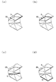
図3(a)および図3(b)に本発明と同様の下貼り型の製造システムにおける気流の速度ベクトルを示す。図3(a)・(b)における領域Aは巻出部が設置される領域であり、領域Bは主に偏光フィルムが通過する領域、および、領域Cは巻取部等が設置される領域である。また、HEPAフィルター40からはクリーンエアーが供給される。なお、図3(a)では、クリーンエアーが通過可能なグレーチング41が設置されているため、グレーチング41を介して、気流が垂直方向に移動することが可能である。一方、図3(b)では、グレーチング41が設置されていないため、気流は床に接触した後、床に沿って移動することとなる。
FIG. 3A and FIG. 3B show the velocity vector of the airflow in the under-paste type manufacturing system similar to the present invention. Regions A in FIGS. 3 (a) and 3 (b) are regions where the unwinding part is installed, region B is a region through which the polarizing film mainly passes, and region C is a region where the winding unit and the like are installed. It is. Further, clean air is supplied from the
図3(a)・(b)に示す製造システムは下貼り型であるため、図10(a)・(b)で示したように、偏光フィルムによってHEPAフィルター40からの気流が妨げられない。このため、気流ベクトルの方向はほとんど基板に向う方向となっており、クリーンルームにて好ましい整流環境が実現されているといえる。図3(a)では、グレーチング41が設置され、図3(b)では設置されていないが、両図とも同様の好ましい状態が示されている。なお、図3および図10では、基板搬送機構は水平に形成されているが、一連の構造としては設置されていない。このため、基板搬送機構間を気流が通過可能な構成となっている。基板は後述する反転機構によって保持された後、基板搬送機構間を移送される構成となっている。
Since the manufacturing system shown in FIGS. 3 (a) and 3 (b) is a bottom-attached type, the air current from the
また、製造システム100では、まず、基板5を長辺間口(長辺が搬送方向と直交する)にて搬送し、その後、短辺間口(短辺が搬送方向と直交する)にて搬送する構成となっている。
Moreover, in the
<基板支持装置>
上記第1基板搬送機構61において搬送された上記基板5を反転するに当たり保持する基板支持装置は、複数の基板支持部材によって機械的に挟着する態様や、流体圧の吸引作用を利用して吸着する態様、その他の態様が可能である。
<Substrate support device>
The substrate support device that holds the
吸着部66Sは、図4に示されるように上記第1基板搬送機構61において搬送された基板5の表面の複数箇所を吸着する複数の吸着口が開口した複数の吸着部材によって構成される。これにより基板5の表面は吸着部66に保持される。吸着部66としては、公知の吸着部を用いることができ、例えば、空気吸引方式の吸着部を用いる事ができる。
As shown in FIG. 4, the
基板支持装置66は、図5ないし図7に示されるように機械的に挟着するタイプのもので、コンベアーロール612を備える上記第1基板搬送機構61のフィルムおよび基板の搬送方向の下流端部およびコンベアーロール622を備える上記第2基板搬送機構61のフィルムおよび基板の搬送方向の上流端部に対して、ガタを考慮しても干渉しないように進入して、反転機構65の基板反転部67の反転動作に応じて第1および第2の基板支持部661、662が介挿して配置されるように構成されている基板搬送機構における基板支持装置に関するものである。
The
上記基板支持装置66は、図5に示されるようにフィルムが貼合された基板より大きなサイズの一対の櫛状部材によって構成され、2個の一対の櫛状部材が、基板反転部67に連結したベース部材660に対して相対的に揺動可能に配設されている。
As shown in FIG. 5, the
また基板支持装置66は、図8に示されるようにタクトタイムの短縮の観点より垂直面において180度の角度関係で2個配設され、上記第1および第2基板搬送機構61、62の搬送方向と、該搬送方向に対して直交する幅方向の中間位置に配置された反転機構の2個の基板反転部67に連結するとともに、第1基板搬送機構61の幅方向に延在する第1の基板支持装置66と第2基板搬送機構62の搬送方向に延在する第2の基板支持装置66とが、同一平面において直交するような配置関係にすることも可能である。更にタクトタイムを短縮するために垂直面において90度(60度)の角度関係で基板反転部67に対して4個(6個)の基板支持装置を配設することも可能である。
Further, as shown in FIG. 8, two
すなわち一方の基板支持装置66が、図8に示されるようにコンベアーロール612を備える上記第1基板搬送機構61のフィルムおよび基板の搬送方向の下流端部に対向して進入配置されている時には、他方の基板支持装置66が、コンベアーロール622を備える上記第2基板搬送機構62のフィルムおよび基板の搬送方向の上流端部に対して、介挿され進入配置されるように構成されている。
That is, when one
上記基板支持装置66は、上記基板の反転動作を行う上記基板反転部67に連結した部材に配設され、長方形の基板を長辺または短辺が搬送方向に沿った状態にて搬送する第1基板搬送機構61および上記基板を短辺または長辺が搬送方向に沿った状態にて搬送する第2基板搬送機構62の端部に進入する第1の支持部材661と第2の支持部材662との相対的移動によって、上記第1の支持部材661と第2の支持部材662との間に上記第1基板搬送機構から搬送された上記基板5が、挟着されることによって支持されるとともに、上記第1の支持部材661と第2の支持部材662との相対的移動によって、上記基板反転部67によって反転された上記第1の支持部材661と第2の支持部材662との間に挟着されることによって支持された上記基板5が、挟着による支持が解除され、上記第2基板搬送機構62の端部に載置されるように構成されている。
The
上記第1基板搬送機構61の下流側端部が、幅方向に複数の例えば4個の分割部分61A、61B、61C、61Dに分割され、隣合う分割部分の間に上記第1および第2の支持部材661、662を構成する略E字状の第1および第2の櫛状部材の複数の例えば3個の突出部6611〜6613、6621〜6623が進入する複数の間隙が形成されているとともに、上記第2基板搬送機構62の上流側端部が、搬送方向に複数の例えば4個の分割部分62A、62B、62C、62Dに分割され、隣合う分割部分の間に反転した上記第1および第2の支持部材661、662を構成する上記第1および第2の櫛状部材の複数の突出部6611〜6613、6621〜6623が進入する複数の間隙が形成されている。
The downstream end of the first
図5および図6に示されるように上記第1基板搬送機構61の下流側端部において、幅方向において分割された4個の分割部分61A、61B、61C、61Dには、それぞれ搬送ローラ612が配設され、回転駆動指令に従い回転駆動機構および回転連絡手段(図示せず)を介して、同期させて回転駆動され、下面に偏向フィルムが貼合された上記基板5が図中右方に搬送され、停止位置に到達したら停止するように構成されている。
As shown in FIGS. 5 and 6, at the downstream end of the first
図5および図6に示されるように上記第2基板搬送機構62の上流側端部において、基板の搬送方向において分割された4個の分割部分62A、62B、62C、62Dには、それぞれ搬送ローラ622が配設され、回転駆動指令に従い回転駆動機構および回転連絡手段(図示せず)を介して、同期させて回転駆動され、基板反転部67によって反転され上面に偏向フィルムが貼合された上記基板5が図中右方の第2の貼合装置に搬送されるように構成されている。
As shown in FIGS. 5 and 6, at the upstream end of the second
図5ないし図7に示されるように上記第1および第2の支持部材661、662は、複数の突出部6611〜6613、6621〜6623を備えた第1および第2の櫛状部材であって、制御すベース部660内の一端を支点として揺動する揺動部材によって構成されている。
As shown in FIGS. 5 to 7, the first and
すなわち上記第1および第2の支持部材661、662を構成する複数の突出部6611〜6613、6621〜6623を備えた上記第1および第2の櫛状部材が、揺動駆動機構6630によって一定角度範囲例えば90度の範囲において揺動駆動されるように構成されている。
That is, the first and second comb-like members having a plurality of
上記揺動駆動機構6630は、図9に示されるように上記第1の支持部材661を構成する複数の突出部6611〜6613を備えた上記第1の櫛状部材を揺動駆動する図9中上方の第1の揺動駆動機構6631と、第2の支持部材662を構成する複数の突出部6621〜6623を備えた上記第2の櫛状部材を揺動駆動される図9中下方の第2の揺動駆動機構6632とから成る。
The rocking
上記第1の揺動駆動機構6631は、上記基板の反転動作を行う上記基板反転部67の端部672に上記連絡部673を介して連結したベース部材660の一端に配設された電気的駆動装置としての第1モータによって構成され、揺動指令に基づく駆動力および揺動方向に従って、上記ベース部材660に介挿された中間中空軸6601を揺動回転させることにより、該中間中空軸6601に一体的に連結された上記第1の支持部材661としての上記第1の櫛状部材を構成する上記複数の突出部6611〜6613を揺動回転させるように構成されている。
The first
図5ないし図10に示されるように回転駆動指令に従い回転駆動機構および回転連絡手段(図示せず)を介して、上記第1基板搬送機構61の下流側端部の4個の分割部分61A、61B、61C、61Dにおいて、搬送ローラ612が回転駆動され、下面に偏向フィルムが貼合された上記基板5が図中右方に搬送され、停止位置に到達して停止すると、上記第1の揺動駆動機構6631を構成する電気的駆動装置としての第1モータが、揺動指令に基づく駆動力および揺動方向に従って、上記ベース部材660に介挿された中間中空軸6601を反時計方向に揺動回転させることにより、該中間中空軸6601に一体的に連結された上記第1の櫛状部材を構成する図9中(A)に示されるように垂直状態の上記複数の突出部6611〜6613を反時計方向に90度揺動回転させることにより、図9中(B)に示されるように水平状態の上記第2の櫛状部材を構成する上記複数の突出部6621〜6623との間に、停止している下面に偏向フィルムが貼合された上記基板5を挟着して支持するものである。
As shown in FIGS. 5 to 10, four divided
上記第2の揺動駆動機構6632は、上記基板の反転動作を行う上記基板反転部67の端部672に上記連絡部673を介して連結したベース部材660の他端に配設された電気的駆動装置としての第2のモータによって構成され、その駆動力および揺動方向に従って、上記ベース部材660に介挿された中心軸6602を揺動回転させることにより、該中心軸に一体的に連結された上記第2の支持部材662としての上記第2の櫛状部材を構成する上記複数の突出部6621〜6623を揺動回転させるように構成されている。
The second
上記複数の突出部6611〜6613の反時計方向における90度の揺動回転により、図9中(B)に示されるように水平状態の上記第2の櫛状部材を構成する上記複数の突出部6621〜6623との間に、停止している下面に偏向フィルムが貼合された上記基板5が挟着され支持されると、後述する基板反転機構の上記基板反転部67が反転軸回りに反転するので、図10(A)に示されるように上記基板5を挟着している上記複数の突出部6611〜6613と上記複数の突出部6621〜6623との上下関係が反転して、上記第2基板搬送機構の上流側端部に基板5を載置する。
The plurality of protrusions constituting the second comb-like member in a horizontal state as shown in FIG. 9B by the swinging rotation of the plurality of
上記第2の揺動駆動機構6632を構成する電気的駆動装置としての第2モータが、揺動指令に基づく駆動力および揺動方向に従って、上記ベース部材660に介挿された中心軸6602を反時計方向に揺動回転させることにより、該中心軸6602に一体的に連結された上記第2の櫛状部材を構成する図10中(A)に示されるように水平状態の上記複数の突出部6621〜6623を反時計方向に揺動回転させることにより、図10中(B)に示されるように90度揺動回転させて、垂直状態にするので、上記第1の櫛状部材を構成する上記複数の突出部6611〜6613との間に、挟着していた下面に偏向フィルムが貼合された上記基板5の挟着状態を解除して、上記第2基板搬送機構の搬送ローラ622の回転によって、第2貼合装置に下面に偏向フィルムが貼合された上記基板5を搬送するものである。
A second motor as an electric drive device constituting the second
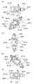
上記揺動駆動機構6630は、図11(A)に示されるように揺動駆動源としての1個のモータ6630と、該モータ6630からの揺動駆動力を上記第1の支持部材661を構成する複数の突出部6611〜6613を備えた上記第1の櫛状部材に回転連絡して揺動駆動する第1クラッチ手段6633と、上記揺動駆動源としての1個のモータ6630からの揺動駆動力を上記第2の支持部材662を構成する複数の突出部6621〜6623を備えた上記第2の櫛状部材に回転連絡して揺動駆動する第2クラッチ手段6634とから構成するもので、揺動駆動源としてのモータ6630を1個にするので、基板支持装置の簡素化、軽量化に適している。
As shown in FIG. 11A, the
上記揺動駆動機構6630は、図11(B)に示されるように第1および第2の揺動駆動源としてアクチュエータ6635、6636を用いて、一部を支点として揺動する揺動部材によって第1および第2の支持部材661、662の他端を図中上下に移動させることにより、を構成して、上記第1および第2の支持部材661、662を構成する上記第1および第2の櫛状部材の複数の突出部6611〜6613、6621〜6623を上記支点を中心にして一定角度範囲例えば0度から±30度前後それぞれ揺動させることにより、上記基板5の挟着支持および挟着支持状態の解除を可能にする態様が可能であり、コントローラ6637によって上記アクチュエータ6635、6636を構成するソレノイドの電流の印加制御すなわちオンオフ制御で実現するものであるので、制御が簡単であるという利点を有する。
As shown in FIG. 11B, the
上述においては、上記第1および第2の支持部材661、662を相対的に揺動回転することにより、上記基板5を挟着支持する例について説明したが、実施形態を上記第1および第2の支持部材を構成する複数の突出部を備えた上記第1および第2の櫛状部材が、上下方向において相対的に接近または離隔して対向間隔が変化するように往復動可能に構成することが可能である。
In the above description, the example in which the
すなわち上記第1および第2の支持部材661、662を構成する複数の突出部6611〜6613、6621〜6623を備えた上記第1および第2の櫛状部材が、直線的駆動機構すなわち往復動駆動機構によって駆動され、往復動するように構成することが可能である。
That is, the first and second comb-like members having a plurality of
前記直線的駆動機構が、図12(A)に示されるようにコントローラ6638Cからの駆動電流に従い第1および第2のソレノイド6638A、6638B他の電気的駆動装置の図12中上下方向の駆動力によって、上記第1および第2の支持部材661、662の少なくとも一方が相対的に接近することにより、上記基板5を挟着して支持するとともに、反転後上記第2の基板搬送機構の上流端において、上記第1および第2の支持部材661、662の少なくとも一方が相対的に離隔することにより、上記基板5の挟着状態を解除するように構成することも可能である。
As shown in FIG. 12 (A), the linear drive mechanism is driven by the drive force in the vertical direction in FIG. 12 of the first and
また前記直線的駆動機構が、図12(B)に示されるように基板支持部材661を構成する櫛状部材の複数の突出部の基板5との接触面に上記基板5を吸着する吸着部6639を複数形成して、駆動装置としてのポンプPから供給される流体圧による負圧吸引作用により、上記基板5を吸着または挟着することによって、上記第1および第2の櫛状部材が相対的に接近することにより、上記基板を挟着して支持するように構成することが可能であり、駆動装置としてのポンプや圧力源を工場内の適宜箇所に設置して配管連絡にすれば、基板支持装置の構成をシンプルにして、軽量化および高速化が可能になるという利点を有する。
Further, as shown in FIG. 12 (B), the linear drive mechanism has an adsorbing
また図12(C)に示されるように第1および第2の支持部材661、662の両端に被吸着部と吸着部6639を複数形成して、駆動装置としての真空ポンプのような吸引ポンプPから配管を介して供給される流体圧(負圧)による負圧吸引作用により、被吸着部が上記吸着部6639に吸着されることにより、上記第1の支持部材661を図中上方に移動させて、上記第1および第2の支持部材661、662との間に基板を挟着支持するように構成することが可能であり、駆動装置としてのポンプや圧力源を工場内の適宜箇所に設置して配管連絡にすれば、基板支持装置の構成をシンプルにして、軽量化および高速化が可能になるという利点を有する。上記実施形態は、吸着部による吸引作用により基板を吸着する態様について、説明したが、吐出口からエアーその他の圧力流体を吐出して、その押圧力によって基板5を支持する態様も可能である。
Further, as shown in FIG. 12C, a plurality of sucked portions and sucked
また偏光フィルムの貼合装置における基板支持装置は、長方形の基板を長辺または短辺が搬送方向に沿った状態にて搬送する第1基板搬送機構61と、上記第1基板搬送機構61における上記基板の下面に第1の偏光フィルムを貼合する第1貼合部6と、上記基板を短辺または長辺が搬送方向に沿った状態にて搬送する第2基板搬送機構62と、上記第2基板搬送機構における上記基板の下面に第2の偏光フィルムを貼合する第2貼合部16と、上記第1基板搬送機構にて搬送され第1の偏光フィルムが貼合された上記基板5を支持する基板支持部を備えた基板支持装置66とを含む偏光フィルムの貼合装置において、上記基板の反転動作を行う基板反転部67に連結したベース部材660に配設され、上記第1基板搬送機構61および第2基板搬送機構62の端部に進入する第1の支持部材661と第2の支持部材662との相対的移動によって、上記第1の支持部材661と第2の支持部材662との間に上記第1基板搬送機構61から搬送された第1の偏光フィルムが貼合された上記基板5が、挟着されることによって支持されるとともに、上記第1の支持部材661と第2の支持部材662との相対的移動によって、上記基板反転部67によって反転された上記第1の支持部材661と第2の支持部材662との間に挟着されることによって支持された第1の偏光フィルムが貼合された上記基板5が、挟着による支持が解除され、上記第2基板搬送機構62の端部に載置されるように構成されているものである。
Moreover, the board | substrate support apparatus in the bonding apparatus of a polarizing film is the said 1st board |
さらに偏光フィルムの貼合装置における基板支持機構は、長方形の基板を長辺または短辺が搬送方向に沿った状態にて搬送する第1基板搬送機構61と、上記第1基板搬送機構における上記基板の下面に第1の偏光フィルムを貼合する第1貼合部6と、上記基板を短辺または長辺が搬送方向に沿った状態にて搬送する第2基板搬送機構62と、上記第2基板搬送機構における上記基板の下面に第2の偏光フィルムを貼合する第2貼合部16と、上記第1基板搬送機構61にて搬送され第1の偏光フィルムが貼合された上記基板を支持する基板支持部に連結した基板反転部67の反転動作により、上記基板支持部に支持された上記基板を反転させるとともに、配置を変更して第2基板搬送機構に配置するように構成されている反転機構を含む偏光フィルムの貼合装置において、上記基板の反転動作を行う上記反転機構の基板反転部67に連結したベース部材660に配設され、上記第1基板搬送機構61および第2基板搬送機構62の端部に進入する第1の支持部材661と第2の支持部材662との相対的移動によって、上記第1の支持部材661と第2の支持部材662との間に上記第1基板搬送機構61から搬送された第1の偏光フィルムが貼合された上記基板5が、挟着されることによって支持されるとともに、上記第1の支持部材661と第2の支持部材662との相対的移動によって、上記基板反転部67によって反転された上記第1の支持部材661と第2の支持部材662との間に挟着されることによって支持された第1の偏光フィルムが貼合された上記基板5が、挟着による支持が解除され、上記第2基板搬送機構の端部に載置されるように構成されている。
Further, the substrate support mechanism in the polarizing film laminating apparatus includes a first
上記偏光フィルムの貼合装置において、上記反転機構が、上記基板の搬送方向に対して直交する第1および第2の基板搬送機構61、62の幅方向の中間位置に配設された反転機構のベース部670に回転可能に配置され、反転動作を実現する基板反転部67を備えている。
In the polarizing film laminating apparatus, the reversing mechanism is a reversing mechanism disposed at an intermediate position in the width direction of the first and second
上記基板支持部材のその他の態様について、以下説明する。
基板支持部は、基板5を支持する部材であり、載置した基板を挟持可能である。また、基板支持部は基板5を吸着する吸着手段を好ましい形態として備えている。吸着手段としては、公知のものを用いることができ、例えば、空気吸引方式の吸着手段を用いることができる。基板支持部はパイプ状のアームおよび吸着手段から構成されており、吸着手段にて吸引された空気がアーム中を通過する構成となっているが、アームおよび吸着手段の形状は当該構成に限定されるものではない。
Other aspects of the substrate support member will be described below.
A board | substrate support part is a member which supports the board |
また、基板支持部はアームに吸着手段が2つ備えられた構造となっており、3本のアームからなるアーム群を1対備えている。また、吸着手段は基板5の対角線上に4つ配置されており、基板5の長さ方向において、上記吸着手段間にさらに吸着手段が2つ配置されている。当該アームの本数および吸着手段の設置数はあくまで一例であり、例えば、大きな基板を反転させる場合には、アームの本数および吸着手段の数を増加させるなど適宜変更すればよい。また、吸着手段の設置場所を基板5の中心部分に集中させる、または、基板5の端部周辺に変更するなどの変更ももちろん可能である。
The substrate support portion has a structure in which two suction means are provided on the arm, and includes a pair of arm groups each including three arms. Further, four suction means are arranged on the diagonal line of the
基板反転部が基板5を載置していない場合、基板5を受け入れ可能なようにアーム群間の距離が広がった状態となっている(以下、この状態を「待機状態」と称する)。一方、基板反転部67は基板5もアーム群間の距離が広がった状態となっている。また、1対のアーム群は基板5を挟持するため、アーム群間の距離を狭めることもできる。このようにアーム群間の距離は変更可能であり、そのために基板支持部は、モーターを有しており、モーターの回転運動を直線運動に変えてアーム群間の距離を変更する構成となっている。なお、アーム群間の距離を変更できる構成であれば、モーターを備える構成に変えて用いてもよい。
When the substrate reversing unit does not place the
上記構成より成る本実施例の偏向フィルムの貼合装置は、上記基板支持装置66が、上記基板の反転動作を行う基板反転部67に連結したベース部材660に配設され、長方形の基板を長辺または短辺が搬送方向に沿った状態にて搬送する上記第1基板搬送機構61および上記基板を短辺または長辺が搬送方向に沿った状態にて搬送する第2基板搬送機構62の端部に進入する第1の支持部材661と第2の支持部材662との相対的移動によって、上記第1の支持部材661と第2の支持部材662との間に上記第1基板搬送機構61から搬送された上記基板5が、挟着されることによって支持されるとともに、上記第1の支持部材661と第2の支持部材662との相対的移動によって、上記基板反転部67によって反転された上記第1の支持部材661と第2の支持部材662との間に挟着されることによって支持された上記基板5が、挟着による支持が解除され、上記第2基板搬送機構62の端部に載置されるものであるので、シンプルな構成によって、上記第1基板搬送機構61によって搬送された上記基板5が、上記第1基板搬送機構61の端部に進入した上記第1の支持部材661および第2の支持部材662との間に挟着されることによって、確実に支持されるという効果を奏するとともに、上記基板反転部67による上記基板の反転を可能にするとともに、上記基板反転部67によって反転された上記第1の支持部材661と第2の支持部材662との間に挟着されることによって支持された上記基板が、挟着による支持が解除され、上記第2基板搬送機構62の端部に載置されることによって、上記第2基板搬送機構62における上記基板の搬送および偏向フィルムの貼合を可能にするという効果を奏する。
In the polarizing film laminating apparatus of this embodiment having the above-described configuration, the
また本実施例の偏向フィルムの貼合装置は、上記第1基板搬送機構61の端部における幅方向の複数の分割部分61A、61B、61C、61Dの隣合う部分の間に形成された複数の間隙に、上記第1および第2の支持部材661、662を構成する第1および第2の櫛状部材の複数の突出部6611〜6613、6621〜6623が進入することにより、上記第1および第2の櫛状部材の複数の突出部との間に、上記第1基板搬送機構61から搬送された上記基板5が、挟着されることによって確実に支持されるという効果を奏するとともに、上記第2基板搬送機構62の端部における搬送方向の複数の分割部分62A、62B、62C、62Dの隣合う部分の間に形成された複数の間隙に、反転した上記第1および第2の支持部材661、662を構成する第1および第2の櫛状部材の複数の突出部6611〜6613、6621〜6623が進入して、反転した上記基板の挟着による支持が解除され、上記第2基板搬送機構62の端部に載置されることによって、上記第2基板搬送機構62における上記基板の搬送および偏向フィルムの貼合を可能にするという効果を奏する。
In addition, the polarizing film laminating apparatus of the present embodiment includes a plurality of
さらに本実施例の偏向フィルムの貼合装置は、上記第1基板搬送機構61の端部における幅方向の複数の分割部分の隣合う部分の間に形成された複数の間隙に、上記第1および第2の支持部材661、662を構成する第1および第2の櫛状部材の複数の突出部が進入して、少なくとも一方の上記第1および第2の櫛状部材の複数の突出部6611〜6613、6621〜6623が、一部を支点として一定角度範囲において揺動することにより、上記第1基板搬送機構61から搬送された上記基板5が、上記第1および第2の櫛状部材の複数の突出部との間に挟着されることによって確実に支持されるという効果を奏するとともに、上記第2基板搬送機構62の端部における搬送方向の複数の分割部分の隣合う部分の間に形成された複数の間隙に、反転した上記第1および第2の支持部材661、662を構成する第1および第2の櫛状部材の複数の突出部が進入して、少なくとも一方の上記第1および第2の櫛状部材の複数の突出部が、一部を支点として一定角度範囲において揺動することにより、反転した上記基板の挟着による支持が解除され、上記第2基板搬送機構62の端部に載置されることによって、上記第2基板搬送機構62における上記基板の搬送および偏向フィルムの貼合を可能にするという効果を奏する。
Further, the polarizing film laminating apparatus of the present embodiment is arranged such that the first and second gaps are formed between adjacent portions of the plurality of divided portions in the width direction at the end of the first
また本実施例の偏向フィルムの貼合装置は、上記第1および第2の支持部材661、662を構成する複数の突出部6611〜6613、6621〜6623を備えた上記第1および第2の櫛状部材が、上記揺動駆動機構によって揺動駆動されることにより、上記第1基板搬送機構61から搬送された上記基板5が、上記第1および第2の櫛状部材の複数の突出部6611〜6613、6621〜6623との間に挟着されることによって確実に支持されるという効果を奏するとともに、反転した上記基板5の挟着による支持が解除され、上記第2基板搬送機構62の端部に載置されることによって、上記第2基板搬送機構62における上記基板5の搬送および偏向フィルムの貼合を可能にするという効果を奏する。
Moreover, the polarizing film laminating apparatus of the present embodiment includes the first and second combs including a plurality of projecting
さらに本実施例の偏向フィルムの貼合装置は、上記揺動駆動機構を構成する上記第1の揺動駆動機構6631が、上記第1の支持部材661を構成する複数の突出部6611〜6613、6621〜6623を備えた上記第1の櫛状部材を揺動駆動するとともに、上記揺動駆動機構を構成する第2の揺動駆動機構6632が、第2の支持部材662を構成する複数の突出部を備えた上記第2の櫛状部材を揺動駆動することにより、上記第1基板搬送機構61から搬送された上記基板5が、上記第1および第2の櫛状部材の複数の突出部6611〜6613、6621〜6623との間に挟着されることによって確実に支持されるという効果を奏するとともに、反転した上記基板の挟着による支持が解除され、上記第2基板搬送機構62の端部に載置されることによって、上記第2基板搬送機構62における上記基板の搬送および偏向フィルムの貼合を可能にするという効果を奏する。
Further, in the deflection film laminating device of the present embodiment, the first
また本実施例の偏向フィルムの貼合装置は、上記揺動駆動機構が、揺動駆動源6630と、上記揺動駆動源からの揺動駆動力を上記第1クラッチ手段6633を介して上記第1の支持部材661を構成する複数の突出部6611〜6613を備えた上記第1の櫛状部材に伝達して揺動駆動するとともに、上記揺動駆動源6630からの揺動駆動力を上記第2クラッチ手段6634を介して上記第2の支持部材662を構成する複数の突出部6621〜6623を備えた上記第2の櫛状部材に伝達して揺動駆動することにより、上記第1基板搬送機構61から搬送された上記基板5が、上記第1および第2の櫛状部材の複数の突出部との間に挟着されることによって確実に支持されるという効果を奏するとともに、反転した上記基板5の挟着による支持が解除され、上記第2基板搬送機構62の端部に載置されることによって、上記第2基板搬送機構62における上記基板5の搬送および偏向フィルムの貼合を可能にするという効果を奏する。
Further, in the deflection film laminating device of the present embodiment, the swing drive mechanism is configured such that the
さらに本実施例の偏向フィルムの貼合装置は、上記第1基板搬送機構61の端部における幅方向の複数の分割部分61A、61B、61C、61Dの隣合う部分の間に形成された複数の間隙に、上記第1および第2の支持部材661、662を構成する第1および第2の櫛状部材の複数の突出部6611〜6613、6621〜6623が進入して、少なくとも一方の上記第1および第2の櫛状部材の複数の突出部が、上下方向において相対的に接近することにより、上記第1基板搬送機構61から搬送された上記基板5が、上記第1および第2の櫛状部材の複数の突出部との間に挟着されることによって確実に支持されるという効果を奏するとともに、上記第2基板搬送機構62の端部における搬送方向の複数の分割部分62A、62B、62C、62Dの隣合う部分の間に形成された複数の間隙に、反転した上記第1および第2の支持部材61、62を構成する第1および第2の櫛状部材の複数の突出部6611〜6613、6621〜6623が進入して、少なくとも一方の上記第1および第2の櫛状部材の複数の突出部が、上下方向において相対的に離隔することにより、反転した上記基板の挟着による支持が解除され、上記第2基板搬送機構62の端部に載置されることによって、上記第2基板搬送機構62における上記基板5の搬送および偏向フィルムの貼合を可能にするという効果を奏する。
Furthermore, the polarizing film laminating apparatus of the present embodiment has a plurality of portions formed between adjacent portions of the plurality of divided
また本実施例の偏向フィルムの貼合装置は、上記直線的駆動機構6638A、Bによって、上記第1および第2の支持部材661、662を構成する複数の突出部6611〜6613、6621〜6623を備えた上記第1および第2の櫛状部材が直線駆動され、往復動することにより、上記第1基板搬送機構61から搬送された上記基板5が、上記第1および第2の櫛状部材の複数の突出部との間に挟着されることによって確実に支持されるという効果を奏するとともに、反転した上記基板5の挟着による支持が解除され、上記第2基板搬送機構62の端部に載置されることによって、上記第2基板搬送機構62における上記基板5の搬送偏向フィルムの貼合を可能にするという効果を奏する。
Moreover, the polarizing film laminating apparatus of the present embodiment is provided with a plurality of
さらに本実施例の偏向フィルムの貼合装置は、前記直線的駆動機構が、電気的駆動装置6638A、Bの駆動力によって、上記第1および第2の支持部材661、662を構成する櫛状部材が相対的に接近することにより、上記基板5を挟着して支持するものであるので、駆動指令に基づく上記電気的駆動装置の駆動力によって、上記基板を挟着して支持する制御を容易に実現にするという効果を奏する。
Further, in the deflection film laminating device of this embodiment, the linear drive mechanism is a comb-like member that constitutes the first and
また本実施例の偏向フィルムの貼合装置は、前記直線的駆動機構が、駆動装置から供給される流体圧の作用により、吸着または挟着することによって、上記第1および第2の支持部材661、662を構成する櫛状部材が相対的に接近することにより、上記基板5を挟着して支持するものであるので、流体圧を供給する駆動装置を上記前記基板支持部材とは別に配置することにより、上記前記基板支持部材の構成をシンプルにして、軽量化を可能にするという効果を奏する。
Further, in the deflection film laminating apparatus of the present embodiment, the linear driving mechanism is adsorbed or sandwiched by the action of fluid pressure supplied from the driving apparatus, whereby the first and
さらに本実施例の偏向フィルムの貼合装置は、上記基板の反転動作を行う基板反転部67に連結するベース部材660に配設され、長方形の基板を長辺または短辺が搬送方向に沿った状態にて搬送する上記第1基板搬送機構61および上記基板を短辺または長辺が搬送方向に沿った状態にて搬送する第2基板搬送機構62の端部に進入する第1の支持部材661と第2の支持部材662との相対的移動によって、上記第1の支持部材661と第2の支持部材662との間に上記第1基板搬送機構61から搬送された第1の偏光フィルムが貼合された上記基板5が挟着されることによって確実に支持されるという効果を奏するとともに、上記第1の支持部材661と第2の支持部材662との相対的移動によって、上記基板反転部67によって反転された上記第1の支持部材661と第2の支持部材662との間に挟着されることによって支持された第1の偏光フィルムが貼合された上記基板5が、挟着による支持が解除され、上記第2基板搬送機構62の端部に載置されるものであるので、上記ベース部材660に連結した上記基板反転部67によって、第1の偏光フィルムが貼合された上記基板を上記基板を短辺または長辺が搬送方向に沿った状態にて搬送する第2基板搬送機構62の端部への上記基板反転部67の反転動作および上記第2貼合部16による第2の偏光フィルムの貼合を可能にするという効果を奏する。
Furthermore, the deflection film laminating apparatus of this example is disposed on the
また本実施例の偏光フィルムの貼合装置は、上記基板支持装置が、上記基板の反転動作を行う上記反転機構の基板反転部67に連結したベース部材660に配設され、上記第1基板搬送機構61および第2基板搬送機構62の端部に進入する第1の支持部材661と第2の支持部材662との相対的移動によって、上記第1の支持部材661と第2の支持部材662との間に上記第1基板搬送機構61から搬送された第1の偏光フィルムが貼合された上記基板5が、挟着されることによって支持されるので、第1の偏光フィルムが貼合された上記基板5が確実に支持されるという効果を奏するとともに、上記第1の支持部材と第2の支持部材との相対的移動によって、上記基板反転部67によって反転された上記第1の支持部材661と第2の支持部材662との間に挟着されることによって支持された第1の偏光フィルムが貼合された上記基板5が、挟着による支持が解除され、上記第2基板搬送機構62の端部に載置されるので、上記ベース部材660に連結した上記基板反転部67によって、第1の偏光フィルムが貼合された上記基板5を上記基板を短辺または長辺が搬送方向に沿った状態にて搬送する第2基板搬送機構62の端部への上記基板反転部67の反転動作および上記第2貼合部16における第2の偏光フィルムの貼合を可能にするという効果を奏する。
Further, the polarizing film laminating apparatus of the present embodiment is arranged such that the substrate support device is disposed on the
<反転機構>
反転機構65は、第1基板搬送機構にて搬送された基板5を反転させて第2基板搬送機構に配置する部材である。上記第1基板搬送機構と第2基板搬送機構とは同一方向に向かって配置されている。図4は反転機構65を示す斜視図である。反転機構65は、第1基板反転部(基板反転部)67および第2基板反転部(基板反転部)68を備えている。
<Reversing mechanism>
The reversing
第1基板反転部67は棒状の形状であり、吸着部66を備えている。第1基板反転部67は自身の軸方向に回転することが可能であり、吸着部66を介して、軸に対して垂直方向に基板5を移動させることができる。また、第1基板反転部67は、第2基板反転部68と連結されている。当該連結部分は駆動可能であり、第1基板反転部67はその位置を変更することができ、基板5の位置を変更することができる。
The first
また、第2基板反転部68は、2つのアーム構造に加え、台部が水平に回転可能な構造となっている。2つのアーム構造によって、基板5を上下方向に移動可能であり、台部の回転により、基板5を水平方向に回転させることができる。
In addition to the two arm structures, the second
本実施の形態では基板反転部として、第1基板反転部67および第2基板反転部68の構造を示したが、基板反転部は当該構成に限定されるものではない。例えば、好ましい形態として制御部を有するロボットアームを用いることができる。ロボットアームを用いた場合、より精密な基板5の操作が可能であるため好ましい。ロボットアームとしては公知のロボットアームを用いることができる。
In the present embodiment, the structure of the first
次に、第1基板反転部67および第2基板反転部68による基板5の反転について説明する。図13は、基板5が反転する際の軌道を示す斜視図である。図13(a)は図4における基板5の状態に対応している。基板5の軌道が把握し易いように吸着部66、第1基板反転部67および第2基板反転部68は図示を省略している。
Next, the reversal of the
まず、第1基板搬送機構から基板5の短辺が搬送方向に沿った状態にて基板5が搬送される。図13(a)のように、基板5は、図示しない第1基板反転部67の手前にて停止し、吸着部66が基板5の表面に吸着する。基板5は、最終的には、図13(d)のように、第1基板搬送機構の搬送方向に沿った短辺が搬送方向に対して直交する方向に沿うように、第2基板搬送機構に配置される。
First, the
第1基板反転部67および第2基板反転部68は、図13(a)における基板5の状態を図13(d)における基板5の状態に変更するように、基板5が曲線を描くように移動させる。すなわち、緩やかな1の動作によって基板5を移動させる。したがって、本実施例における基板5の反転は、直線的な移動、例えば、基板5の1辺に沿った方向への反転させる移動を伴うものではない。また、当該動作は、基板の反転および基板の水平方向における旋回の2の動作を連続させる動作ではないし、これら2つの動作を同時に行うものでもない。
The first
図13(a)における基板5は、図13(b)〜(d)に示すように、その一方の(図中左側の)短辺を内側、他方の(図中右側)短辺を外側として移動される。具体的には、図4に示されるロポットの各軸の回転駆動系が切られ、作業者によってロボットの各軸を動かすことが出来る状態であって、動かされたロボットの各軸の角度および変位がセンサによって検知されるティーチングモードにおいて、作業者によって以下に述べるように基板5の姿勢とその姿勢を実現するロボットの各軸の角度および変位が教示され、記憶される。図13(a)では、基板5が位置している水平面から基板5が持ち上げられ、内側短辺よりも外側短辺の方が高い位置となるよう、基板5が傾いた状態にて移動される。基板5' は基板5が移動した後の位置を示している。また、曲線69は、基板5および基板5' において互いに対応する頂点同士を結んだ基板5の軌跡を示している。第1基板反転部67および第2基板反転部68は曲線を描くように基板5を移動させる。換言すると、基板が曲線の軌跡に沿って移動するともいえる。上記曲線は円弧であり、直線でなく滑らかな軌跡である。上述のティーチング以外にも図13に示される円弧軌跡に従って基板が反転移動するようにロボットの各軸の角度および変位データを作成して予め制御装置のROMに格納しておき、かかるデータに従ってロボットを動作させることにより、図13に示される円弧軌跡に従って基板が反転移動させる実施例も採用可能である。
As shown in FIGS. 13B to 13D, the
基板5は、図13(b)および(c)に示す状態を経由して、最終的に図13(d)に示す状態に移動される。図13(d)の基板5の配置は、図13(a)の基板5が反転し、搬送方向に沿った短辺が長辺となるように変更された配置である。
The
さらに、図14を用いて基板5の配置を変更させる過程について説明する。図14(a)〜(d)は、反転機構65によって基板5を反転させる過程を示す平面図である。図14(a)〜(d)の基板5の配置はそれぞれ、図13(a)〜(d)における基板5の配置に対応している。
Further, a process of changing the arrangement of the
図14は、図4における基板5の回転過程を示す平面図である。図14では、反転機構65に加えて第1基板搬送機構61および第2基板搬送機構62を図示している。第1基板搬送機構61および第2基板搬送機構62にはコンベアーロールが備えられおり、これによって基板5が搬送される。また、第1基板搬送機構61と第2基板搬送機構62とは同一方向に向かって配置されている。すなわち、L字型形状などの複雑な構造を有していない。したがって、本発明に係る貼合装置60は、設置が非常に簡便であり、面積効率に優れる。
FIG. 14 is a plan view showing the rotation process of the
まず、図14(a)のように、吸着部66が基板5の表面に吸着し、基板5の表面が保持される。その後、図14(d)の基板5の配置となるように、図13(a)〜(c)で示した曲線69の軌跡を辿り基板5の移動がなされる。図13(d)に示す位置に基板5が到達した後には、吸着部66の吸着が解除されることにより基板5の保持が解かれた後、基板5は第2基板搬送機構62によって搬送される。そして、反転機構65は図6(a)の位置に戻り、順次搬送される他の基板5を同様の動作にて反転させる。
First, as shown in FIG. 14A, the
本実施例の反転機構65によれば、結果として、1つの動作によって、(1)基板5は反転されると共に、(2)第1基板搬送機構61の搬送方向に沿った長辺または短辺が搬送方向に対して直交する方向に沿うように配置される。このため、1つの動作によって、基板5の2つの状態を変更させることができる。
According to the reversing
このように1つの反転機構65によって2つの作用を生ぜしめるため、短いタクトタイムにて基板5の反転が可能である。つまり、1つの反転機構65によって基板5の反転および搬送方向に沿った辺の変更を行うため、貼合装置60におけるライン長を圧迫することもない。
As described above, since two functions are generated by one reversing
また、反転機構65によって基板5に対して反転および搬送方向に沿った辺の変更を行った後、ニップロール16・16aによって、基板5に対して下面から偏光フィルムを貼合することができる。これにより、貼合装置60によって基板5の両面に対して共に下面から偏光フィルムが貼合されることとができ、整流環境を妨げることもない。
Further, after the reversing
図14では、第1基板搬送機構61および第2基板搬送機構62はその搬送方向が一直線上に配置されず、隣接した構造となっている。これは、図14(a)の基板5と、図14(d)の基板5とを比較すると、互いに対応する頂点同士の複数の中点を結んだ直線が、第1基板搬送機構61における基板5の搬送方向に対して45°の角度となっている。このように、第1基板搬送機構61との搬送方向と、第2基板搬送機構62での基板5の搬送方向とは同一方向に向かう、すなわち平行ではあるものの同一直線上にはないからである。なお、図14(d)の基板5の配置はあくまで一例であり、厳密に当該配置とする必要はない。
In FIG. 14, the first
図5ないし図7に示される実施例の反転機構は、ベース部670に対して図中上下方向のように一方向に伸縮自在の往復部671と、該往復部671内に介挿され図中水平面において90度の範囲内において回転する回転部672と、該回転部672の上端に配設された2個の支持部6731、6732内に回転自在に挿入されたモータ6733によって180度の範囲内において回転駆動される回転軸6734に一体的に配設され、上記基板支持装置66のベース部材660の一端に配設されたモータ6630に一体的に連結した基板反転部としての基板反転部材673とから成る。
The reversing mechanism of the embodiment shown in FIGS. 5 to 7 is inserted in the
上記モータ6733によって回転駆動される上記回転軸6734が、反転機構の基板反転部673の反転軸を構成するもので、往復部671内に介挿され図中水平面において90度の範囲内において回転する回転部672が、配置変更部材であり、該回転部672の回転軸心が配置変更軸である。
The
上記基板反転部材673は、制御装置からの制御信号によって図5および図7に示される第1基板搬送機構61の下流端の幅方向に延在する状態から図中手前方向に180度反転するものであるが、その時上記回転部672が反時計方向に90度回転駆動されるため、90度回転した時には、図6に示されるように第2基板搬送機構62の上流端の搬送方向に延在する状態になり、第1基板搬送機構61の下流端に搬送された基板5を第2基板搬送機構62の上流端に配置方向を90度変更して配置して、搬送を可能にするものである。
The
上記回転部672の反時計方向の回転は、図5に示される状態においては、上記第1基板搬送機構61の下流側端部の幅方向に分割された複数の例えば4個の分割部分61A、61B、61C、61Dの隣合う分割部分の間に上記第1および第2の支持部材661、662を構成する略E字状の第1および第2の櫛状部材の複数の例えば3個の突出部6611〜6613、6621〜6623が進入している状態であるため、上記分割部分61A、61B、61C、61Dと上記突出部6611〜6613、6621〜6623との干渉の回避、円弧軌跡の制御、その他の観点のために、上記基板反転部材673が上方に回転して、上記3個の突出部6611〜6613、6621〜6623が、上記分割部分61A、61B、61C、61Dより上方に位置して進入状態が解消された反転角度15度以上、30度、45度から、上記回転部672の反時計方向の回転を開始するとともに、図6に示される上記第2基板搬送機構62の上流側端部の複数の例えば4個の分割部分62A、62B、62C、62D内に、第1および第2の櫛状部材の複数の突出部6611〜6613、6621〜6623が進入を開始する前の反転角度135度以上、150度、165度までに上記回転部672の反時計方向の回転が終了するように回転位相を任意に設定することが出来る。
In the state shown in FIG. 5, the
上記構成より成る反転機構は、90度の範囲内において回転する上記回転部672の上端に配設された2個の支持部6731、6732内に回転自在に挿入された上記回転軸6734回りに180度の範囲内において基板反転部としての基板反転部材673が反転するものであるため、複合された一連の円弧軌跡に沿った移動によって、上記第1基板搬送機構61の下流側端部において支持された基板5を反転させるとともに、上記第2基板搬送機構62の上流側端部に上記第2基板搬送機構62における搬送方向に沿う方向に変更して配置するものであるため、タクトタイムの短縮を可能にするものである。
The reversing mechanism having the above-described configuration is 180 around the
図8、図15および図16に示される実施例の反転機構は、ベース部670に対して図中上下方向のように一方向に伸縮自在の略L字状の往復部671と、該L字状の往復部671の先端部に配設された基板反転用の駆動モータ6733と、該駆動モータ6733の回転軸6734の先端に一体的に配設された固着部6735と、該固着部6735に一部が固着された上下のリング部材6736、6737と、該上下のリング部材6736、6737の間に形成される空間内に図中反時計方向に回転可能に介挿された中間回転部材6738と、該中間回転部材6738の外周壁に円周角で90度の角度関係になるように固着され、第1基板搬送機構61の下流端の幅方向に延在するとともに、第2基板搬送機構62の上流端の搬送方向に延在する上記基板支持装置66の2個のベース部材660の一端に配設されたモータ6630に一体的に連結した第1および第2の基板反転部673とから成る。
The reversing mechanism of the embodiment shown in FIG. 8, FIG. 15 and FIG. 16 has a substantially L-shaped
上記駆動モータ6733の上記回転軸6734は、反転機構の反転軸を構成するもので、第1および第2の基板搬送機構の基板搬送方向と平行に配置されており、上下のリング部材6736、6737の間に形成される空間内に図中反時計方向に回転可能に介挿された中間回転部材6738は、配置変更部材を構成するもので、該中間回転部材6738の回転中心が配置変更軸である。
The
上記基板反転部材673は、制御装置からの制御信号に基づく駆動モータ6733の回転によって、図8、図15および図16に示される第1基板搬送機構61の下流端の幅方向および第2基板搬送機構62の上流端の搬送方向にそれぞれ延在する状態から図の紙面厚さ方向上方および下方に180度反転するものであるが、その時上記中間回転部材6738および90度の角度関係で配設された第1および第2の基板反転部673が時計方向に回転駆動源(図示せず)によって90度回転駆動されるため、90度回転した時には、図8に示されるように第1基板搬送機構61の下流端において支持された基板5が、円弧状軌跡に沿って移動して第2基板搬送機構62の上流端の搬送方向に延在する状態になるとともに、第2基板搬送機構62の上流端において支持された基板5が、円弧状軌跡に沿って移動して第1基板搬送機構61の下流端の下流端の幅方向に延在する状態になるものである。
The
本実施例も上述の実施例と同様に、上記基板支持装置66の上記分割部分61A、61B、61C、61Dと上記突出部6611〜6613、6621〜6623との干渉の回避、円弧軌跡の制御、その他の観点のために、上記基板反転部材673が上方および下方に回転して、上記3個の突出部6611〜6613、6621〜6623が、上記分割部分61A、61B、61C、61Dより上方および下方に位置して進入状態が解消された反転角度15度以上、30度、45度から、上記中間回転部材6738の時計方向の回転を開始するとともに、図8に示される上記第2基板搬送機構62の上流側端部の複数の例えば4個の分割部分62A、62B、62C、62D内に、第1および第2の櫛状部材の複数の突出部6611〜6613、6621〜6623が進入を開始する前の反転角度135度以上、150度、160度までに上記中間回転部材6738の時計方向の回転が終了するように回転位相を任意に設定することが出来る。
Similarly to the above-described embodiment, this embodiment also avoids interference between the divided
上記上下のリング部材6736、6737が上方および下方に45度回転した状態になった時には、図15(C)および図16図(B)に示されるように上記中間回転部材6738が時計方向に22.5度回転駆動されるので、上記中間回転部材6738の外周壁に90度の角度関係で配設された第1および第2の基板反転部673が時計方向に22.5度回転駆動されるのて、回転軸6734を中心にした回転と 上記中間回転部材6738の回転軸を中心にした回転とが複合された円弧軌跡に沿った移動によってそれぞれ22.5度および112.5度の状態になる。
When the upper and
上記上下のリング部材6736、6737が上方および下方に90度回転して、垂直状態になった時には、図15(C)および図16図(C)に示されるように上記中間回転部材6738が時計方向に45度回転駆動されるので、上記中間回転部材6738の外周壁に90度の角度関係で配設された第1および第2の基板反転部673が時計方向に45度回転駆動されるのて、上記複合された円弧軌跡に沿った移動によってそれぞれ45度および135度の状態になる。
When the upper and
上記上下のリング部材6736、6737が上方および下方に135度回転した状態になった時には、図15(C)および図16図(D)に示されるように上記中間回転部材6738が時計方向に135度回転駆動されるので、上記中間回転部材6738の外周壁に90度の角度関係で配設された第1および第2の基板反転部673が時計方向に62.5度回転駆動されるのて、上記複合された円弧軌跡に沿った移動によってそれぞれ62.5度および152.5度の状態になる。
When the upper and
上記上下のリング部材6736、6737が上方および下方に180度回転した状態になった時には、図15(C)および図16図(E)に示されるように上記中間回転部材6738が時計方向に180度回転駆動されるので、上記中間回転部材6738の外周壁に90度の角度関係で配設された第1および第2の基板反転部673が時計方向に90度回転駆動されるのて、上記複合された円弧軌跡に沿った移動によってそれぞれ90度および180度の状態になる。
When the upper and
本実施例の基板反転部67および基板支持装置66は、図8、図15(E)、図16(A)に示されるように垂直面において180度の角度関係で2個配設され、上記第1および第2基板搬送機構61、62の搬送方向と、該搬送方向に対して直交する幅方向の中間位置に配置された反転機構の2個の基板反転部673に連結するとともに、第1基板搬送機構61の幅方向に延在する第1の基板支持装置66と第2基板搬送機構62の搬送方向に延在する第2の基板支持装置66とが、同一平面において直交するような配置関係にしたので、180度基板反転部67が反転すると、上記複合された一連の円弧軌跡に沿った移動によって第1および第2の基板反転部67が入れ替わり、次の基板の支持および反転を直ちに行うことが出来るため、図4および図5に示される実施例よりタクトタイムの短縮を可能にするものである。
As shown in FIG. 8, FIG. 15 (E), and FIG. 16 (A), two
図17は、反転機構65を2つ用いた貼合装置60の変形例を示す平面図である。当該変形例の変更点としては、(1)反転機構65が2つであり、(2)第1基板搬送機構61に基板載置部61aが備えられており、(3)第1基板搬送機構61および第2基板搬送機構62が一直線上に配置されている点である。なお、第1基板搬送機構61および第2基板搬送機構62が同一方向に向かって配置されている点は同じである。
FIG. 17 is a plan view showing a modification of the
基板載置部61aおよび反転機構65は、第1基板搬送機構61における第2基板搬送機構62側の端部において、上記端部の第1基板搬送機構61の搬送方向に対して水平な両方向に沿って備えられている。反転機構65は図4、図13および図14にて説明した構造である。また、上記端部には、基板載置部61aへ基板5を搬送する搬送手段が備えられており、具体的には、例えば、コンベアーロールを挙げることができる。
The
基板載置部61aは、反転機構65による基板5の移動前において、基板5が搬送される終点となる場である。当該構造によれば、第1基板搬送機構61に搬送された基板5は、搬送手段によって2つの基板載置部61aに交互に搬送される。基板載置部61aおよび反転機構65は2対ずつ備えられており、2つの反転機構65に交互に搬送される複数の基板5は、第2基板搬送機構62に順次移動させられる。
The
当該変形例では、2つの基板載置部61aは第1基板搬送機構61の水平な両方向に沿ってそれぞれ備えられているため、反転した基板5は、第1基板搬送機構61の搬送方向に沿って配置されることとなる。したがって、第1基板搬送機構61および第2基板搬送機構62を一直線上に配置することが可能である。
In the modified example, the two
当該変形例によれば、(1)反転機構65が2つ備えられているため、基板5を単位時間当り2倍処理することができる。これにより、単位時間当たり多くの基板5の反転が可能なため、タクトタイムが短縮される。(2)さらに、第1基板搬送機構61および第2基板搬送機構62が一直線上に配置されているため、より面積効率に優れた構造の貼合装置を提供できる。特にクリーンルームにおいては面積効率が要求されるため、当該貼合装置は非常に好ましい。
According to the modification, (1) since two reversing
<その他の付帯的構成>
さらに、好ましい形態として、製造システム100は、制御部70、洗浄部71、貼りずれ検査装置72および貼合異物自動検査装置73および仕分け搬送装置74を備えている。貼りずれ検査装置72、貼合異物自動検査装置73および仕分け搬送装置74は、貼合後の基板5、すなわち、液晶表示装置に対して検査等の処理を行うものである。
<Other incidental configurations>
Furthermore, as a preferable form, the
図18は上記液晶表示装置の製造システムが備える各部材の関連を示すブロック図であり、図19は液晶表示装置の製造システムの動作を示すフローチャートである。以下、液晶表示装置が備える各部材の説明と共にその動作について説明する。 FIG. 18 is a block diagram showing the relationship of each member provided in the liquid crystal display device manufacturing system, and FIG. 19 is a flowchart showing the operation of the liquid crystal display device manufacturing system. Hereinafter, the operation of the liquid crystal display device will be described together with the description of each member.
制御部70は、反転部65、洗浄部71、貼りずれ検査装置72、貼合異物自動検査装置73および仕分け搬送装置74と接続されており、これらに制御信号を送信して制御するものである。制御部70は、主としてCPU(Central Processing Unit )により構成され、必要に応じてメモリ等を備える。
The
製造システム100に洗浄部71が備えられている場合、洗浄部71でのタクトタイムを短縮するため、第1基板搬送機構61における基板5は、長辺間口にて洗浄部71に搬送されることが好ましい。通常、洗浄部71での洗浄は長時間を要するため、タクトタイムを短縮する観点から当該構成は非常に有効である。
In the case where the
次に、偏光フィルムを基板5の両面に貼合する貼合工程を行うが(図19のS2)、本工程については、図1〜図17を用いて説明した通りである。
Next, although the bonding process which bonds a polarizing film on both surfaces of the board |
貼りずれ検査装置72は、貼合された基板5における偏光フィルムの貼りずれの有無を検査するものである。貼りずれ検査装置72は、カメラおよび画像処理装置によって構成されており、ニップロール16・16aによって偏光フィルムが貼合された基板5の貼合位置に上記カメラが設置されている。上記カメラにて基板5の撮影が行われ、撮影された画像情報を処理することによって、基板5に貼りずれの有無を検査することができる(貼りずれ検査工程、図9のS3)。なお、貼りずれ検査装置72としては、従来公知の貼りずれ検査装置を使用可能である。
The sticking
貼合異物自動検査装置73は、貼合された基板5における異物の有無を検査するものである。貼合異物自動検査装置73は、貼りずれ検査装置72と同様に、カメラおよび画像処理装置によって構成されており、ニップロール16・16aによって偏光フィルムが貼合された後の基板5の第2基板搬送機構62(貼合装置60)に上記カメラが設置されている。上記カメラにて基板5の撮影が行われ、撮影された画像情報を処理することによって、基板5に貼合異物の有無を検査することができる(貼合異物検査工程、S4)。上記異物としては、埃などの異物、フィッシュアイなどが挙げられる。なお、貼合異物自動検査装置73としては、従来公知の貼合異物検査装置を使用可能である。
The bonded foreign matter
S3およびS4は逆の順序でなされてもよいし、同時になされてもよい。また、一方の工程を省略することも可能である。 S3 and S4 may be performed in the reverse order or simultaneously. One step can be omitted.
仕分け搬送装置74は、貼りずれ検査装置72および貼合異物自動検査装置73からの検査結果に基づき、貼りずれおよび異物の有無を判定する。仕分け搬送装置74は、貼りずれ検査装置72および貼合異物自動検査装置73から検査結果に基づく出力信号を受信して、貼合された基板5を良品または不良品に仕分けできるものであればよい。したがって、従来公知の仕分け搬送システムを用いることができる。
The sorting and conveying
当該液晶表示装置の製造システムでは好ましい態様として貼りずれおよび異物の両方を検出する構成となっており、貼りずれまたは異物が検査されたと判定された場合(YES)、貼合された基板5は不良品として仕分けされる(S7)。一方、貼りずれおよび異物のいずれもが検知されなかったと判定された場合(NO)、貼合された基板5は良品として仕分けされる(S6)。
In the manufacturing system of the liquid crystal display device, as a preferred mode, both the misalignment and foreign matter are detected. When it is determined that the misalignment or foreign matter has been inspected (YES), the bonded
仕分け搬送装置74を備える液晶表示装置の製造システムによれば、良品および不良品の仕分けを速やかに行うことができ、タクトタイムを短縮することが可能である。貼りずれ検査装置72または貼合異物自動検査装置73のみが備えられている場合、仕分け搬送装置74は、貼りずれおよび異物の一方のみ有無を判定する構成であってもよい。
According to the manufacturing system of the liquid crystal display device provided with the sorting and conveying
さらに本実施例の偏光フィルムの貼合装置および液晶表示装置の製造システムは、上記基板支持装置が、上記偏光フィルムの貼合装置が含む上記反転機構が備える上記基板反転部67が、回転して反転動作するものであるので、上記基板反転部の一回の反転動作による円弧軌跡に沿う移動により、第1の偏光フィルムが貼合された上記基板の搬送方向に沿ってオフセットした位置において短辺および長辺の方向を変更することが出来るとともに、タクトタイムを短くすることが出来るという効果を奏する。
Further, in the polarizing film laminating apparatus and the liquid crystal display manufacturing system of the present embodiment, the
また本実施例の偏光フィルムの貼合装置は、上記基板支持装置が、上記偏光フィルムの貼合装置が含む上記反転機構が備える上記基板反転部67が、反転して反転動作するものであるので、上記基板反転部の上記一回の反転動作による円弧軌跡に沿う移動により、第1の偏光フィルムが貼合された上記基板の搬送方向に沿ってオフセットした位置において短辺および長辺の方向を変更することが出来るとともに、タクトタイムを短くすることが出来るという効果を奏する。
Moreover, since the said board |
なお、本発明は、上述した各実施形態に限定されるものではなく、請求項に示した範囲およびその精神に基づいて種々の変更が可能であり、異なる実施例にそれぞれ開示された技術的手段を適宜組み合わせて得られる実施形態についても本発明の技術的範囲に含まれる。 Note that the present invention is not limited to the above-described embodiments, and various modifications are possible based on the scope and spirit of the claims, and technical means disclosed in different embodiments. Embodiments obtained by appropriately combining the above are also included in the technical scope of the present invention.
本発明に係る偏光フィルムの貼合装置は、偏光フィルムを基板に貼合する分野にて利用可能である。 The polarizing film bonding apparatus according to the present invention can be used in the field of bonding a polarizing film to a substrate.
1 第1巻出部
1a 第2巻出部
2 第1巻取部
2a 第2巻取部
3 ハーフカッター
4 ナイフエッジ
5・5' 基板
5a 偏光フィルム
5b 剥離フィルム
6・6a ニップロール(第1貼合部)
7・7a 欠点フィルム巻取ローラー
11 第1巻出部
11a 第2巻出部
12 第1巻取部
12a 第2巻取部
13 ハーフカッター
14 ナイフエッジ
16・16a ニップロール(第2貼合部)
17・17a 欠点フィルム巻取ローラー
40 HEPAフィルター
41 グレーチング
50 フィルム搬送機構
51 第1フィルム搬送機構
52 第2フィルム搬送機構
60 貼合装置(偏光フィルムの貼合装置)
61 第1基板搬送機構
61a 基板載置部
62 第2基板搬送機構
65 反転機構
66 基板支持装置
66S 吸着部
67 第1基板反転部(基板反転部)
68 第2基板反転部(基板反転部)
69 曲線
70 制御部
71 洗浄部
72 貼りずれ検査装置
73 貼合異物自動検査装置
74 仕分け搬送装置
100 製造システム(液晶表示装置の製造システム)
DESCRIPTION OF
7.7a Defect
17.17a Defect
61 1st board |
68 Second substrate reversing part (substrate reversing part)
69
Claims (22)
上記第1基板搬送機構における上記基板の下面に偏光フィルムを貼合する第1貼合部と、
上記第1基板搬送機構にて搬送された上記基板を反転させて第2基板搬送機構に配置する反転機構と、
上記基板を短辺または長辺が搬送方向に沿った状態にて搬送する第2基板搬送機構と、
上記第2基板搬送機構における上記基板の下面に偏光フィルムを貼合する第2貼合部とを含む偏光フィルム貼合装置であって、
上記第1基板搬送機構と第2基板搬送機構とは同一方向に向かって配置されており、
上記反転機構は上記基板を吸着する吸着部と、
上記吸着部に連結されており、基板を反転させる基板反転部とを備えており、 上記基板反転部は、第1基板搬送機構における基板を、(1)曲線を描くように、(2)反転させながら、(3)第1基板搬送機構の搬送方向に沿った長辺または短辺が搬送方向に対して直交する方向に沿うように、第2基板搬送機構に配置することを特徴とする偏光フィルムの貼合装置。 A first substrate transport mechanism for transporting a rectangular substrate with a long side or a short side along the transport direction;
A first bonding unit for bonding a polarizing film to the lower surface of the substrate in the first substrate transport mechanism;
A reversing mechanism for inverting the substrate transported by the first substrate transporting mechanism and placing it on the second substrate transporting mechanism;
A second substrate transport mechanism for transporting the substrate in a state where the short side or the long side is along the transport direction;
A polarizing film laminating apparatus including a second laminating unit for laminating a polarizing film on the lower surface of the substrate in the second substrate transport mechanism,
The first substrate transport mechanism and the second substrate transport mechanism are arranged in the same direction,
The reversing mechanism includes a suction portion that sucks the substrate;
A substrate reversing unit that is connected to the suction unit and reverses the substrate, and the substrate reversing unit is configured to (2) invert the substrate in the first substrate transport mechanism so as to draw a curve (1) (3) Polarization characterized by being arranged in the second substrate transport mechanism so that the long side or the short side along the transport direction of the first substrate transport mechanism is along the direction orthogonal to the transport direction. Film bonding device.
上記第1基板搬送機構における上記基板の下面に偏光フィルムを貼合する第1貼合部と、
上記第1基板搬送機構にて搬送された上記基板を支持する基板支持部を備えた基板支持装置と、
上記基板支持部に連結して該基板支持部に支持された基板を反転させて配置する基板反転部を備えた反転機構と、
上記反転機構によって反転させるとともに短辺または長辺が搬送方向に沿った状態にて配置された上記基板を搬送する第2基板搬送機構と、
上記第2基板搬送機構における上記基板の下面に偏光フィルムを貼合する第2貼合部とを含む偏光フィルム貼合装置であって、
上記第1基板搬送機構と第2基板搬送機構とは同一方向に向かって配置されており、
上記反転機構は、上記基板の表面が裏面になるように基板反転部を反転させる反転軸および上記第1基板搬送機構において搬送される上記基板の配置方向から上記第2基板搬送機構において搬送される上記基板の配置方向に配置変更部によって変更される配置変更軸回りに一定角度範囲で回転させることにより、上記第1基板搬送機構において搬送された上記基板を円弧軌跡を描いて反転させるとともに、上記第2基板搬送機構における基板の搬送方向に沿うように配置を変更して、上記第2基板搬送機構に対して配置されるように構成されている
ことを特徴とする偏光フィルムの貼合装置。 A first substrate transport mechanism for transporting a rectangular substrate with a long side or a short side along the transport direction;
A first bonding unit for bonding a polarizing film to the lower surface of the substrate in the first substrate transport mechanism;
A substrate support device comprising a substrate support unit for supporting the substrate transported by the first substrate transport mechanism;
A reversing mechanism provided with a substrate reversing unit that is connected to the substrate supporting unit and arranged to reverse the substrate supported by the substrate supporting unit;
A second substrate transport mechanism that transports the substrate that is reversed by the reversing mechanism and that has the short side or the long side disposed along the transport direction;
A polarizing film laminating apparatus including a second laminating unit for laminating a polarizing film on the lower surface of the substrate in the second substrate transport mechanism,
The first substrate transport mechanism and the second substrate transport mechanism are arranged in the same direction,
The reversing mechanism is transported by the second substrate transport mechanism from a reversing axis that reverses the substrate reversing unit so that the front surface of the substrate is the back surface and the arrangement direction of the substrate transported by the first substrate transport mechanism. The substrate transported in the first substrate transport mechanism is reversed by drawing an arc locus by rotating the substrate in the layout direction by a fixed angle range around the placement change axis changed by the placement changing unit in the placement direction of the substrate. A polarizing film bonding apparatus, wherein the arrangement is changed so as to be along the substrate conveyance direction in the second substrate conveyance mechanism and arranged with respect to the second substrate conveyance mechanism.
前記反転機構は、前記基板反転部が前記配置変更部に回転可能に配設された前記反転軸を備える反転軸部に連結して、回転駆動源によってそれぞれ回転駆動されるように構成されている
ことを特徴とする偏光フィルムの貼合装置。 In claim 2,
The reversing mechanism is configured such that the substrate reversing unit is connected to a reversing shaft unit including the reversing shaft rotatably disposed on the arrangement changing unit, and is rotated by a rotation driving source. The polarizing film bonding apparatus characterized by the above-mentioned.
前記反転機構は、前記配置変更部が前記反転軸を備える反転軸部に連結した前記基板反転部に相対回転可能に配設され、回転駆動源によってそれぞれ回転駆動されるように構成されている
ことを特徴とする偏光フィルムの貼合装置。 In claim 2,
The reversing mechanism is configured such that the arrangement changing unit is disposed so as to be relatively rotatable on the substrate reversing unit connected to the reversing shaft unit including the reversing shaft and is driven to rotate by a rotation driving source. A polarizing film laminating apparatus.
上記基板支持装置の上記基板支持部が、上記第1基板搬送機構にて搬送された上記基板の両面を挟着して支持する複数の支持部材によって構成されている
ことを特徴とする偏光フィルムの貼合装置。 In any one of Claims 2 thru | or 4,
The substrate support unit of the substrate support apparatus is configured by a plurality of support members that sandwich and support both surfaces of the substrate transported by the first substrate transport mechanism. Bonding device.
上記基板支持装置の上記基板支持部が、上記第1基板搬送機構にて搬送された上記基板の表面を吸着する吸着部を備えた吸着部材によって構成されている
ことを特徴とする偏光フィルムの貼合装置。 In any one of Claims 2 thru | or 4,
The polarizing film pasting, wherein the substrate supporting part of the substrate supporting device is constituted by an adsorbing member having an adsorbing part that adsorbs the surface of the substrate conveyed by the first substrate conveying mechanism. Combined device.
上記基板支持装置が、上記基板の反転動作を行う基板反転部に連結した部材に配設され、上記第1基板搬送機構および第2基板搬送機構の端部に進入する第1の支持部材と第2の支持部材との相対的移動によって、上記第1の支持部材と第2の支持部材との間に上記第1基板搬送機構から搬送された上記基板を、挟着することによって支持するとともに、上記第1の支持部材と第2の支持部材との相対的移動によって、上記基板反転部によって反転された上記第1の支持部材と第2の支持部材との間に挟着されることによって支持された上記基板を、挟着による支持を解除して、上記第2基板搬送機構の端部に載置するように構成されている
ことを特徴とする偏光フィルムの貼合装置。 In claim 3 or claim 4,
The substrate supporting device is disposed on a member connected to a substrate reversing unit that performs the reversing operation of the substrate, and a first supporting member and a first supporting member that enter the end portions of the first substrate transporting mechanism and the second substrate transporting mechanism. And by supporting the substrate transported from the first substrate transport mechanism between the first support member and the second support member by sandwiching the substrate by relative movement with the second support member, Supported by being sandwiched between the first support member and the second support member reversed by the substrate reversing part by the relative movement of the first support member and the second support member. The polarizing film laminating apparatus is configured to release the support by clamping and place the substrate on the end portion of the second substrate transport mechanism.
上記第1基板搬送機構の端部が、幅方向に複数の部分に分割され、隣合う部分の間に上記第1および第2の支持部材を構成する第1および第2の櫛状部材の複数の突出部が進入する複数の間隙が形成されているとともに、上記第2基板搬送機構の端部が、搬送方向に複数の部分に分割され、隣合う部分の間に反転した上記第1および第2の支持部材を構成する上記第1および第2の櫛状部材の複数の突出部が進入する複数の間隙が形成されている
ことを特徴とする偏光フィルムの貼合装置。 In claim 3 or claim 4,
The end portions of the first substrate transport mechanism are divided into a plurality of portions in the width direction, and a plurality of first and second comb-like members that constitute the first and second support members between adjacent portions. A plurality of gaps into which the protrusions of the first substrate and the second substrate transport mechanism enter, and an end portion of the second substrate transport mechanism is divided into a plurality of portions in the transport direction and inverted between adjacent portions. A polarizing film laminating apparatus, wherein a plurality of gaps into which a plurality of protrusions of the first and second comb-shaped members constituting the two supporting members enter are formed.
上記第1および第2の支持部材を構成する複数の突出部を備えた第1および第2の櫛状部材が、一部を支点として一定角度範囲において揺動するように構成されている
ことを特徴とする偏光フィルムの貼合装置。 In claim 8,
The first and second comb-like members having a plurality of protrusions constituting the first and second support members are configured to swing within a certain angle range with a part as a fulcrum. A polarizing film laminating apparatus.
上記第1および第2の支持部材を構成する複数の突出部を備えた上記第1および第2の櫛状部材が、揺動駆動機構によって揺動駆動されるように構成されている
ことを特徴とする偏光フィルムの貼合装置。 In claim 9,
The first and second comb-like members having a plurality of protrusions constituting the first and second support members are configured to be driven to swing by a swing drive mechanism. A polarizing film laminating apparatus.
上記揺動駆動機構は、上記第1の支持部材を構成する複数の突出部を備えた上記第1の櫛状部材を揺動駆動する第1の揺動駆動機構と、第2の支持部材を構成する複数の突出部を備えた上記第2の櫛状部材を揺動駆動される第2の揺動駆動機構とから成る
ことを特徴とする偏光フィルムの貼合装置。 In claim 10,
The swing drive mechanism includes a first swing drive mechanism that swings and drives the first comb-like member having a plurality of protrusions that constitute the first support member, and a second support member. A polarizing film laminating apparatus comprising: a second swing driving mechanism that swings and drives the second comb-shaped member having a plurality of projecting portions.
上記第1および第2の支持部材を構成する複数の突出部を備えた上記第1および第2の櫛状部材が、一方向において相対的に接近または離隔して対向間隔が変化するように往復動可能に構成されている
ことを特徴とする偏光フィルムの貼合装置。 In claim 8,
The first and second comb-like members having a plurality of projecting portions constituting the first and second support members are reciprocated so that the facing distance is changed by relatively approaching or separating in one direction. A polarizing film laminating apparatus, which is configured to be movable.
上記第1および第2の支持部材を構成する複数の突出部を備えた上記第1および第2の櫛状部材が、直線的駆動機構によって駆動され、往復動するように構成されている
ことを特徴とする偏光フィルムの貼合装置。 In claim 12,
The first and second comb-like members having a plurality of projecting portions constituting the first and second support members are driven by a linear drive mechanism and configured to reciprocate. A polarizing film laminating apparatus.
上記第1基板搬送機構および第2基板搬送機構が一直線上に配置されており、
第1基板搬送機構における第2基板搬送機構側の端部において、第1基板搬送機構の搬送方向に対して水平な両方向に沿って、基板載置部および上記反転機構が2対ずつ備えられ、
上記端部には、上記端部から上記基板載置部へ基板を搬送する搬送手段が備えられており、
上記反転機構は上記基板載置部のそれぞれに搬送された基板を反転させて第2基板搬送機構に配置することを特徴とする偏光フィルムの貼合装置。 In claim 1 or claim 2,
The first substrate transport mechanism and the second substrate transport mechanism are arranged on a straight line,
At the end of the first substrate transport mechanism on the second substrate transport mechanism side, two pairs of substrate placement portions and the above reversing mechanisms are provided along both directions parallel to the transport direction of the first substrate transport mechanism,
The end portion is provided with a transport means for transporting the substrate from the end portion to the substrate mounting portion.
The inverted mechanism laminating apparatus of the polarizing film you characterized in that arranged on the second substrate transport mechanism by reversing the substrate transferred to each of said substrate platform.
偏光フィルムを搬送する第1フィルム搬送機構および第2フィルム搬送機構が備えられており、
上記第1フィルム搬送機構には、剥離フィルムに保護された偏光フィルムを巻出す複数の巻出部と、偏光フィルムを切断する切断部と、偏光フィルムから剥離フィルムを除去する除去部と、除去された上記剥離フィルムを巻取る複数の巻取部とが備えられており、
上記第2フィルム搬送機構には、剥離フィルムに保護された偏光フィルムを巻出す複数の巻出部と、偏光フィルムを切断する切断部と、偏光フィルムから剥離フィルムを除去する除去部と、除去された上記剥離フィルムを巻取る複数の巻取部とが備えられており、
上記第1基板搬送機構および第2基板搬送機構は上記第1フィルム搬送機構および第2フィルム搬送機構の上部に備えられており、
上記剥離フィルムが除去された偏光フィルムを基板に貼合する上記第1貼合部が上記第1フィルム搬送機構と第1基板搬送機構との間に、上記剥離フィルムが除去された偏光フィルムを基板に貼合する第2貼合部が上記第2フィルム搬送機構と第2基板搬送機構との間にそれぞれ備えられていることを特徴とする偏光フィルムの貼合装置。 In any of claim 1, claim 2 or claim 14,
A first film transport mechanism and a second film transport mechanism for transporting the polarizing film;
The first film transport mechanism includes a plurality of unwinding sections for unwinding the polarizing film protected by the release film, a cutting section for cutting the polarizing film, and a removing section for removing the peeling film from the polarizing film. And a plurality of winding sections for winding the release film,
The second film transport mechanism includes a plurality of unwinding sections for unwinding the polarizing film protected by the release film, a cutting section for cutting the polarizing film, and a removing section for removing the peeling film from the polarizing film. And a plurality of winding sections for winding the release film,
The first substrate transport mechanism and the second substrate transport mechanism are provided above the first film transport mechanism and the second film transport mechanism,
The first bonding portion for bonding the polarizing film from which the release film has been removed to the substrate is between the first film transport mechanism and the first substrate transport mechanism, and the polarizing film from which the release film has been removed is the substrate. A polarizing film laminating apparatus, wherein a second laminating unit for laminating is provided between the second film conveying mechanism and the second substrate conveying mechanism.
上記第1貼合部によって基板の下面に偏光フィルムを貼合する前に、基板を洗浄する洗浄部を備え、
上記第1基板搬送機構は、基板の短辺が搬送方向に沿った状態にて基板を搬送することを特徴とする偏光フィルムの貼合装置。 In any of claim 1, claim 2, claim 14 or claim 15,
Before the polarizing film is bonded to the lower surface of the substrate by the first bonding unit, a cleaning unit for cleaning the substrate is provided,
The said 1st board | substrate conveyance mechanism conveys a board | substrate in the state in which the short side of the board | substrate followed the conveyance direction, The bonding apparatus of the polarizing film characterized by the above-mentioned.
上記第1フィルム搬送機構および上記第2フィルム搬送機構には、第1巻出部から巻出
された偏光フィルムに付された欠点表示を検出する欠点検出部と、
上記欠点表示を判別して、上記基板の搬送を停止させる貼合回避部と、
基板との貼合が回避された偏光フィルムを回収する回収部とを有することを特徴とする偏光フィルムの貼合装置。 In claim 15,
In the first film transport mechanism and the second film transport mechanism, a defect detection unit that detects a defect display attached to the polarizing film unwound from the first unwinding unit;
A bonding avoidance unit that determines the defect display and stops the conveyance of the substrate,
A polarizing film laminating apparatus comprising: a collecting unit that collects a polarizing film from which pasting with a substrate is avoided.
上記第2貼合部によって偏光フィルムの貼合がなされた基板における貼りずれを検査する貼りずれ検査装置を備えることを特徴とする液晶表示装置の製造システム。 A polarizing film laminating apparatus according to any one of claims 1, 2, and 14 to 17,
The manufacturing system of the liquid crystal display device provided with the sticking deviation test | inspection apparatus which test | inspects the sticking deviation in the board | substrate with which the polarizing film was bonded by the said 2nd bonding part.
上記貼りずれ検査装置による検査結果に基づき貼りずれの有無を判定し、当該判定結果に基づき、偏光フィルムが貼合された基板の仕分けを行う仕分け搬送装置を備えることを特徴とする液晶表示装置の製造システム。 In claim 18,
A liquid crystal display device comprising: a sorting and conveying device that determines the presence or absence of pasting deviation based on an inspection result by the pasting deviation inspection device and sorts a substrate on which a polarizing film is bonded based on the determination result. Manufacturing system.
上記貼合装置における第2貼合部によって偏光フィルムの貼合がなされた基板における異物を検査する貼合異物自動検査装置とを備えることを特徴とする液晶表示装置の製造システム。 A polarizing film laminating apparatus according to any one of claims 1, 2, and 14 to 17,
A manufacturing system for a liquid crystal display device, comprising: a bonded foreign matter automatic inspection device that inspects foreign matter on a substrate on which a polarizing film has been bonded by the second bonding portion in the bonding device.
上記貼合異物自動検査装置による検査結果に基づき異物の有無を判定し、当該判定結果に基づき、偏光フィルムが貼合された基板の仕分けを行う仕分け搬送装置を備えることを特徴とする液晶表示装置の製造システム。 In claim 20,
A liquid crystal display device comprising: a sorting and conveying device that determines the presence or absence of foreign matter based on an inspection result by the bonded foreign matter automatic inspection device and sorts a substrate on which a polarizing film is bonded based on the determination result Manufacturing system.
上記第2貼合部によって偏光フィルムの貼合がなされた基板における異物を検査する貼合異物自動検査装置を備え、
上記貼りずれ検査装置による検査結果、および、上記貼合異物自動検査装置による検査結果に基づき、貼りずれおよび異物の有無を判定し、当該判定結果に基づき、偏光フィルムが貼合された基板の仕分けを行う仕分け搬送装置を備えることを特徴とする液晶表示装置の製造システム。 In claim 18,
It is equipped with a bonded foreign matter automatic inspection device that inspects foreign matters on the substrate on which the polarizing film has been bonded by the second bonding portion,
Based on the inspection result by the pasting inspection device and the inspection result by the pasting foreign matter automatic inspection device, the presence or absence of pasting and foreign matter is determined, and the substrate on which the polarizing film is pasted is determined based on the determination result. A system for manufacturing a liquid crystal display device, comprising: a sorting and conveying device that performs the above.
Priority Applications (1)
| Application Number | Priority Date | Filing Date | Title |
|---|---|---|---|
| JP2011086997A JP5170913B2 (en) | 2010-04-12 | 2011-04-11 | Polarizing film laminating apparatus and liquid crystal display manufacturing system having the same |
Applications Claiming Priority (3)
| Application Number | Priority Date | Filing Date | Title |
|---|---|---|---|
| JP2010091623 | 2010-04-12 | ||
| JP2010091623 | 2010-04-12 | ||
| JP2011086997A JP5170913B2 (en) | 2010-04-12 | 2011-04-11 | Polarizing film laminating apparatus and liquid crystal display manufacturing system having the same |
Publications (3)
| Publication Number | Publication Date |
|---|---|
| JP2011237785A JP2011237785A (en) | 2011-11-24 |
| JP2011237785A5 JP2011237785A5 (en) | 2012-10-25 |
| JP5170913B2 true JP5170913B2 (en) | 2013-03-27 |
Family
ID=44798477
Family Applications (1)
| Application Number | Title | Priority Date | Filing Date |
|---|---|---|---|
| JP2011086997A Expired - Fee Related JP5170913B2 (en) | 2010-04-12 | 2011-04-11 | Polarizing film laminating apparatus and liquid crystal display manufacturing system having the same |
Country Status (5)
| Country | Link |
|---|---|
| JP (1) | JP5170913B2 (en) |
| KR (1) | KR101877066B1 (en) |
| CN (1) | CN102844702B (en) |
| TW (1) | TWI522688B (en) |
| WO (1) | WO2011129093A1 (en) |
Families Citing this family (10)
| Publication number | Priority date | Publication date | Assignee | Title |
|---|---|---|---|---|
| JP6178660B2 (en) * | 2013-08-08 | 2017-08-09 | 住友化学株式会社 | Optical display device production system |
| JP6178661B2 (en) * | 2013-08-08 | 2017-08-09 | 住友化学株式会社 | Optical display device production system |
| CN103708713A (en) * | 2013-12-26 | 2014-04-09 | 深圳市华星光电技术有限公司 | Clamping mechanism, liquid crystal panel cutting machine and liquid crystal panel cutting process |
| KR102208089B1 (en) * | 2015-05-27 | 2021-01-28 | 엘지전자 주식회사 | System for attaching Polarizing film and Method for attaching Polarizing film |
| CN105158936B (en) * | 2015-08-28 | 2019-05-03 | 深圳市华星光电技术有限公司 | The method of robot assemblies and movable glass substrate to carry out substrate in combination |
| CN107817619B (en) * | 2017-11-17 | 2020-07-10 | 武汉华星光电技术有限公司 | Polaroid attaching equipment and system |
| CN108573904B (en) * | 2018-04-14 | 2021-08-20 | 芜湖扬展新材料科技服务有限公司 | Silicon plate mechanical cleaning device |
| CN110109277B (en) * | 2019-04-09 | 2021-07-06 | 惠州市华星光电技术有限公司 | Touch display panel and touch display device |
| CN110015558A (en) * | 2019-05-13 | 2019-07-16 | 航天云网科技发展有限责任公司 | Automatic turning glue machine and automatic turning colloid system |
| CN113945521A (en) * | 2021-10-26 | 2022-01-18 | 上海麟图智能科技有限公司 | Detection method for detecting appearance defects of mobile phone cover plate glass and transmission device thereof |
Family Cites Families (10)
| Publication number | Priority date | Publication date | Assignee | Title |
|---|---|---|---|---|
| JPH11278649A (en) * | 1998-03-30 | 1999-10-12 | Rohm Co Ltd | Board rearranging device for electronic part |
| JP2005037417A (en) * | 2002-06-28 | 2005-02-10 | Fuji Photo Film Co Ltd | Method and apparatus for bonding polarizing plate |
| JP4340788B2 (en) * | 2003-04-22 | 2009-10-07 | シャープ株式会社 | Polarizer pasting device to substrate |
| JP4307510B1 (en) * | 2007-12-27 | 2009-08-05 | 日東電工株式会社 | Optical display device manufacturing system and method |
| JP4785944B2 (en) * | 2008-04-16 | 2011-10-05 | 日東電工株式会社 | Manufacturing method of optical display device |
| CN101581850A (en) * | 2008-05-13 | 2009-11-18 | 郑春晓 | Semi-automatic laminating machine and laminating method thereof |
| KR100971436B1 (en) * | 2008-07-09 | 2010-07-21 | 주식회사 에스에프에이 | System and method for attaching polarizer to glass |
| CN201298126Y (en) * | 2008-09-11 | 2009-08-26 | 郑春晓 | Semiautomatic laminating machine |
| JP4669070B2 (en) * | 2009-05-21 | 2011-04-13 | 日東電工株式会社 | Optical display device manufacturing system and method |
| JP4676026B1 (en) * | 2010-09-17 | 2011-04-27 | 日東電工株式会社 | Liquid crystal display device manufacturing system and manufacturing method |
-
2011
- 2011-04-11 KR KR1020127026690A patent/KR101877066B1/en active IP Right Grant
- 2011-04-11 WO PCT/JP2011/002132 patent/WO2011129093A1/en active Application Filing
- 2011-04-11 JP JP2011086997A patent/JP5170913B2/en not_active Expired - Fee Related
- 2011-04-11 CN CN201180018940.8A patent/CN102844702B/en not_active Expired - Fee Related
- 2011-04-12 TW TW100112631A patent/TWI522688B/en not_active IP Right Cessation
Also Published As
| Publication number | Publication date |
|---|---|
| CN102844702B (en) | 2015-07-29 |
| TW201207493A (en) | 2012-02-16 |
| WO2011129093A1 (en) | 2011-10-20 |
| JP2011237785A (en) | 2011-11-24 |
| CN102844702A (en) | 2012-12-26 |
| KR101877066B1 (en) | 2018-07-10 |
| TWI522688B (en) | 2016-02-21 |
| KR20130056857A (en) | 2013-05-30 |
Similar Documents
| Publication | Publication Date | Title |
|---|---|---|
| JP5170913B2 (en) | Polarizing film laminating apparatus and liquid crystal display manufacturing system having the same | |
| JP5079114B2 (en) | Substrate transport mechanism and substrate support device in polarizing film laminating apparatus | |
| JP4751997B1 (en) | Polarizing film laminating apparatus and liquid crystal display manufacturing system having the same | |
| WO2011122001A1 (en) | Polarizing film lamination device and liquid crystal display manufacture system provided with the same | |
| JP5613582B2 (en) | Polarizing film laminating apparatus and liquid crystal display manufacturing system having the same | |
| JP4676026B1 (en) | Liquid crystal display device manufacturing system and manufacturing method | |
| JP5616054B2 (en) | Polarizing film laminating apparatus and liquid crystal display manufacturing system having the same | |
| JP2011237785A5 (en) | ||
| JP5523916B2 (en) | Polarizing film laminating apparatus and liquid crystal display manufacturing system having the same | |
| JP5144777B2 (en) | Reversing mechanism with substrate support in substrate transport mechanism and polarizing film laminating device | |
| JP4863332B2 (en) | Polarizing film laminating apparatus and liquid crystal display manufacturing system | |
| JP5087174B2 (en) | Liquid crystal display device manufacturing system and method | |
| JP5281725B2 (en) | Substrate transport mechanism and reversing mechanism in polarizing film laminating device |
Legal Events
| Date | Code | Title | Description |
|---|---|---|---|
| A521 | Written amendment |
Free format text: JAPANESE INTERMEDIATE CODE: A523 Effective date: 20120909 |
|
| A621 | Written request for application examination |
Free format text: JAPANESE INTERMEDIATE CODE: A621 Effective date: 20120909 |
|
| A871 | Explanation of circumstances concerning accelerated examination |
Free format text: JAPANESE INTERMEDIATE CODE: A871 Effective date: 20120909 |
|
| A975 | Report on accelerated examination |
Free format text: JAPANESE INTERMEDIATE CODE: A971005 Effective date: 20120928 |
|
| A131 | Notification of reasons for refusal |
Free format text: JAPANESE INTERMEDIATE CODE: A131 Effective date: 20121002 |
|
| A01 | Written decision to grant a patent or to grant a registration (utility model) |
Free format text: JAPANESE INTERMEDIATE CODE: A01 Effective date: 20121218 |
|
| A61 | First payment of annual fees (during grant procedure) |
Free format text: JAPANESE INTERMEDIATE CODE: A61 Effective date: 20121224 |
|
| LAPS | Cancellation because of no payment of annual fees |