WO2012169425A1 - 逆止弁 - Google Patents
逆止弁 Download PDFInfo
- Publication number
- WO2012169425A1 WO2012169425A1 PCT/JP2012/064115 JP2012064115W WO2012169425A1 WO 2012169425 A1 WO2012169425 A1 WO 2012169425A1 JP 2012064115 W JP2012064115 W JP 2012064115W WO 2012169425 A1 WO2012169425 A1 WO 2012169425A1
- Authority
- WO
- WIPO (PCT)
- Prior art keywords
- check valve
- plug
- seal member
- fluid
- main body
- Prior art date
- Legal status (The legal status is an assumption and is not a legal conclusion. Google has not performed a legal analysis and makes no representation as to the accuracy of the status listed.)
- Ceased
Links
Images


Classifications
-
- F—MECHANICAL ENGINEERING; LIGHTING; HEATING; WEAPONS; BLASTING
- F16—ENGINEERING ELEMENTS AND UNITS; GENERAL MEASURES FOR PRODUCING AND MAINTAINING EFFECTIVE FUNCTIONING OF MACHINES OR INSTALLATIONS; THERMAL INSULATION IN GENERAL
- F16K—VALVES; TAPS; COCKS; ACTUATING-FLOATS; DEVICES FOR VENTING OR AERATING
- F16K15/00—Check valves
- F16K15/02—Check valves with guided rigid valve members
- F16K15/025—Check valves with guided rigid valve members the valve being loaded by a spring
- F16K15/026—Check valves with guided rigid valve members the valve being loaded by a spring the valve member being a movable body around which the medium flows when the valve is open
-
- F—MECHANICAL ENGINEERING; LIGHTING; HEATING; WEAPONS; BLASTING
- F16—ENGINEERING ELEMENTS AND UNITS; GENERAL MEASURES FOR PRODUCING AND MAINTAINING EFFECTIVE FUNCTIONING OF MACHINES OR INSTALLATIONS; THERMAL INSULATION IN GENERAL
- F16K—VALVES; TAPS; COCKS; ACTUATING-FLOATS; DEVICES FOR VENTING OR AERATING
- F16K15/00—Check valves
- F16K15/02—Check valves with guided rigid valve members
- F16K15/025—Check valves with guided rigid valve members the valve being loaded by a spring
-
- F—MECHANICAL ENGINEERING; LIGHTING; HEATING; WEAPONS; BLASTING
- F16—ENGINEERING ELEMENTS AND UNITS; GENERAL MEASURES FOR PRODUCING AND MAINTAINING EFFECTIVE FUNCTIONING OF MACHINES OR INSTALLATIONS; THERMAL INSULATION IN GENERAL
- F16K—VALVES; TAPS; COCKS; ACTUATING-FLOATS; DEVICES FOR VENTING OR AERATING
- F16K17/00—Safety valves; Equalising valves, e.g. pressure relief valves
- F16K17/02—Safety valves; Equalising valves, e.g. pressure relief valves opening on surplus pressure on one side; closing on insufficient pressure on one side
- F16K17/04—Safety valves; Equalising valves, e.g. pressure relief valves opening on surplus pressure on one side; closing on insufficient pressure on one side spring-loaded
- F16K17/0466—Safety valves; Equalising valves, e.g. pressure relief valves opening on surplus pressure on one side; closing on insufficient pressure on one side spring-loaded with a special seating surface
-
- F—MECHANICAL ENGINEERING; LIGHTING; HEATING; WEAPONS; BLASTING
- F16—ENGINEERING ELEMENTS AND UNITS; GENERAL MEASURES FOR PRODUCING AND MAINTAINING EFFECTIVE FUNCTIONING OF MACHINES OR INSTALLATIONS; THERMAL INSULATION IN GENERAL
- F16K—VALVES; TAPS; COCKS; ACTUATING-FLOATS; DEVICES FOR VENTING OR AERATING
- F16K25/00—Details relating to contact between valve members and seats
- F16K25/005—Particular materials for seats or closure elements
-
- Y—GENERAL TAGGING OF NEW TECHNOLOGICAL DEVELOPMENTS; GENERAL TAGGING OF CROSS-SECTIONAL TECHNOLOGIES SPANNING OVER SEVERAL SECTIONS OF THE IPC; TECHNICAL SUBJECTS COVERED BY FORMER USPC CROSS-REFERENCE ART COLLECTIONS [XRACs] AND DIGESTS
- Y10—TECHNICAL SUBJECTS COVERED BY FORMER USPC
- Y10T—TECHNICAL SUBJECTS COVERED BY FORMER US CLASSIFICATION
- Y10T137/00—Fluid handling
- Y10T137/7722—Line condition change responsive valves
- Y10T137/7837—Direct response valves [i.e., check valve type]
- Y10T137/7904—Reciprocating valves
- Y10T137/7922—Spring biased
- Y10T137/7924—Spring under tension
Definitions
- This invention relates to a check valve, and more particularly to a check valve suitable for use under high temperature conditions exceeding 200 ° C.
- Patent Document 1 discloses that a plug body urged by a urging member in an opening of a fluid passage provided in a main body is brought into a shut-off state by contacting an O-ring serving as a seal member. When a fluid pressure of a predetermined value or more is loaded in the passage, the plug body is opened by moving against the urging force of the urging member.
- the check valve used in an apparatus maintained at a high temperature is required to have heat resistance.
- the check valve of Patent Document 1 described above is resistant to O-rings.
- the object of the present invention is to provide a check valve that can be used even under high temperature conditions by improving the heat resistance and eliminating the problem of “sticking the plug to the seal member” associated with high temperature use. There is to do.
- the opening of the fluid passage provided in the main body is shut off when the plug body biased by the biasing member comes into contact with the seal member, and the fluid passage of the main body has a predetermined value or more.
- a perfluoroelastomer packing having a secondary vulcanized seal member;
- the stopper is formed with an annular seal portion that comes into line contact with the seal member.
- the seal member is made of perfluoroelastomer packing so that it can be used under high temperature conditions. Thereby, heat resistance is ensured.
- Examples of the perfluoroelastomer include Kalrez (registered trademark).
- the plug is made of an appropriate metal such as stainless steel.
- the present inventor has paid attention to the sticking of the plug body to the seal member, and as a result of performing various analyzes, has obtained the above-described structure as a structure for reducing this sticking.
- Secondary vulcanization is usually performed as a process for removing impurities by heating a molded article in a furnace at a high temperature of about 200 ° C. for several hours to several tens of hours.
- Perfluoroelastomer has excellent chemical resistance and heat resistance, and also has elasticity equivalent to that of rubber. In particular, its heat resistance is excellent, and it has the advantage that it can maintain the same elasticity as rubber even at a high temperature close to 300 ° C., and has less degassing.
- the stopper is formed with a perfluoroelastomer as a material for the sealing member in addition to the annular sealing portion that is in line contact with the sealing member.
- a perfluoroelastomer as a material for the sealing member in addition to the annular sealing portion that is in line contact with the sealing member.
- the plug body has a cylindrical portion in which a fluid escape passage serving as a fluid passage in an open state is formed, and a small-diameter disk portion that is provided continuously to the distal end side of the cylindrical portion and blocks the opening of the main body.
- the annular seal portion is formed by a first inclined surface extending radially outward on a surface on the distal end side of the cylindrical portion and a second inclined surface extending radially outwardly connected to the first inclined surface.
- the seal member has a disc part interposed between the opening edge of the fluid passage of the main body and the annular seal part of the plug, and the crushing margin of the disc part by the annular seal part is 0.05 mm to It is preferable to be 0.15 mm.
- the crushing allowance is the difference between the thickness before being urged by the urging member and the thickness after being urged by the urging member.
- the crushing allowance is 0.05 mm to 0.15 mm,
- the ratio represented by the thickness before being applied is 5.5% to 17%.
- the seal member is a secondary vulcanized perfluoroelastomer packing
- the plug body is formed with an annular seal portion that comes into line contact with the seal member. It is possible to eliminate sticking of the plug to the sealing member that occurs when the air is naturally cooled, and as a result, it is suitable for use under high temperature conditions.
- FIG. 1 is a longitudinal sectional view showing an embodiment of a check valve according to the present invention.
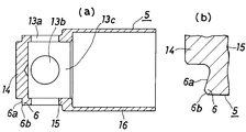
- FIG. 2 is a longitudinal sectional view showing a stopper body of a check valve according to the present invention
- FIG. 2B is an enlarged view of an annular seal portion which is a main part of FIG.
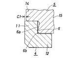
- FIG. 3 is an enlarged longitudinal sectional view showing the positional relationship between the stopper body and the seal member of the check valve according to the present invention.
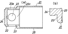
- FIG. 4 is a longitudinal sectional view showing a plug body of a comparative example of a check valve
- FIG. 4B is an enlarged view of an annular seal portion which is a main part of FIG. FIG.
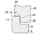
- FIG. 5 is a longitudinal sectional view showing a positional relationship between a plug body and a seal member of a comparative example of the check valve.
- FIG. 6 is a graph showing measurement results of “pressure at the beginning of opening” of the check valve according to the present invention.
- a check valve (1) has a cylindrical first body having a left small-diameter inner peripheral surface (2a) and a right large-diameter inner peripheral surface (2b) as fluid passages.
- (Main body) (2) a large-diameter inner peripheral surface (3a) on the left side, a small-diameter inner peripheral surface (3b) on the right side, and an intermediate inner peripheral surface (3c) with an intermediate diameter therebetween.
- the first body (2) and the second body (3) are formed on the external thread portion provided on the outer periphery of the right portion of the first body (2) and the large-diameter inner peripheral surface (3a) of the second body (3). Since it is provided, it is coupled by screwing with the threaded portion.
- the sealing member (4) is a secondary vulcanized perfluoroelastomer packing, the opening edge of the small-diameter inner peripheral surface (2a) of the first body (2) and the sealing portion of the plug (5). (6) and a cylindrical part (12) extending rightward from the outer peripheral edge of the disk part (11).
- the outer diameter of the seal member (4) is substantially equal to the inner diameter of the large-diameter inner peripheral surface (2b) of the first body (2), and the inner diameter is the same as that of the small-diameter inner peripheral surface (2a) of the first body (2). It is made larger than the inner diameter.
- the plug body (5) is connected to the cylindrical part (13) in which the fluid escape passages (13a), (13b) and (13c) are formed, and to the left side (tip side) of the cylindrical part (13) and more than the cylindrical part (13).
- the plug body (5) has the left surface of the outer peripheral edge portion of the small-diameter disk portion (14) brought into contact with the right end opening edge portion of the small-diameter inner peripheral surface (2a) of the first body (2), and the cylinder
- the right end opening of the peripheral surface (fluid passage) (2a) is in a blocked state.
- the fluid relief passages (13a), (13b), and (13c) of the cylindrical part (13) are formed so as to guide the fluid on the outer peripheral surface of the cylindrical part (13) into the large-diameter cylindrical part (15).
- the urging member (7) is a cylindrical compression coil spring, and its left end surface is received by the right surface of the cylindrical portion (13) of the plug (5), and its right end surface is the second body ( It is received by a step portion (3e) formed between the small-diameter inner peripheral surface (3b) and the intermediate inner peripheral surface (3c) of 3).
- the gland packing (8) is provided at the cylindrical portion (16), the inward flange portion (17) provided at the left end opening edge of the cylindrical portion (16), and the right end opening edge of the cylindrical portion (16). And an outward flange portion (18).
- the inward flange portion (17) is in contact with the right surface of the cylindrical portion (12) of the seal member (4).
- the outward flange portion (18) has a substantially rectangular shape elongated in the axial direction, and the left end surface of the first body (2), the large-diameter inner peripheral surface (3a) and the intermediate inner peripheral surface of the second body (3). (3c) between the first body (2) and the second body (3), and is deformed by a predetermined amount when the first body (2) and the second body (3) are screwed together. The space between the first body (2) and the second body (3) is sealed.
- this check valve (1) in the state shown in FIG. 1, the sealing portion (6) of the plug (5) urged by the urging member (7) is connected to the disc portion ( The blocking state is obtained by abutting on 11) from the right.
- the fluid is introduced into the small-diameter inner peripheral surface (2a) of the first body (2), and the shut-off state is continued while the pressure of the fluid is smaller than the urging force by the urging member (7).
- the plug body (5) moves to the right against the urging force of the urging member (7) due to the fluid pressure, and the small-diameter inner periphery of the first body (2).
- the sealing portion (6) of the plug (5) (the surface in contact with the sealing member (4)) is a small-diameter disk portion ( 14), a first inclined surface (6a) extending radially outward from a boundary with the first and the second inclined surface (6b) extending radially outwardly from the first inclined surface (6a).
- FIG. 3 is a view showing the positional relationship between the sealing member (4) and the plug body (5) before being urged by the urging member (7).
- FIG. 6 is in line contact with the seal member (4) and has C1 as a crushing allowance.
- the plug (5) moves to the left, and the small-diameter disk portion (14) of the plug (5) as shown in FIG.
- the left surface (tip surface) of the first member abuts on the opening edge of the small-diameter inner peripheral surface (2a) of the first body (2) and is flush with the left surface of the seal member (4).
- the seal member (4) exhibits a seal function by being compressed by the crushing amount C1.
- FIG. 4 shows a plug body (21) as a comparative example.
- the plug body (21) includes a cylindrical portion (23) in which fluid escape passages (23a), (23b) and (23c) are formed, and a cylindrical body.
- the sealing portion (22) of the plug (21) is a flat surface of the outer peripheral edge of the left surface of the cylindrical portion (23).
- FIG. 5 shows the seal member before being urged by the urging member (7) when the same seal member (4) used in FIG. 3 is combined with the plug (21) shown in FIG. (4) is a diagram showing the positional relationship between the plug body (21), in which the annular seal portion (22) of the plug body (21) is in surface contact with the seal member (4) and is crushed. As an alternative, it has C2.
- FIGS. 2 and 3 is suitable for the comparative example shown in FIGS. 4 and 5 under high temperature use conditions.
- the present inventor paid attention to the sticking of the plugs (5) and (21) to the seal member (4), and under various conditions, the pressure at which the opening began (reverse) The pressure value when the fluid relief function of the stop valve (1) appears was measured.
- “Stick” means that the sealing member (packing) (4) is in close contact with the plug body (5) (21). In this case, the plug body (5) (21) is moved by the fluid pressure. A fluid pressure corresponding to the urging force + contact force of the urging member (7) is required, and the pressure at the beginning of opening increases as the contact force increases.
- C1 in FIG. 3 is set to 0.1 mm
- C2 in FIG. 5 is set to 0.3 mm
- a seal member (4) having a thickness of the disk portion (11) of 0.9 mm is combined.
- An example of the measurement results is shown in FIG.
- the pressure to start opening after applying a pressure of 1 MPa from the right side of the check valve (1) shown in FIG. 1, the fluid is gradually introduced from the left side to gradually increase the pressure, and the first body (2) The fluid pressure just before the opening of the small-diameter inner peripheral surface (2a) opened and the pressure decreased was measured.
- FIG. 6 shows secondary vulcanization in the shape of FIG. 2 and FIG. 3 (line contact type) for three conditions of initial setting (before temperature increase), after temperature increase and after natural cooling (natural cooling after temperature increase). None, secondary vulcanization with the shape of FIG. 2 and FIG. 3 (line contact type), no secondary vulcanization with the shape of FIG. 4 and FIG. 5 (surface contact type), and the shape of FIG. 4 and FIG. 5 (surface contact) The results of evaluation of four types with secondary vulcanization are shown.
- the sticking is particularly large after the temperature rise and natural cooling, and the surface contact type has a large sticking after the cooling.
- the sticking after cooling is reduced and can be lowered to the same level as the initial setting of the surface contact type.
- secondary vulcanization it is possible to reduce sticking in both the surface contact type and the line contact type.
- the pressure at the beginning of opening is small and Fluctuation due to conditions is small.
- the plug (5) and the seal member (4) are in line contact, and the perfluoroelastomer that is the material of the seal member (4) is It can be seen that the secondary vulcanization is more preferable.
- FIG. 1 shows the line check valve (1) in which the bodies (2) and (3) have a shape similar to a pipe joint
- the check valve of the present invention is not limited to this.
- the opening of the fluid passage provided in the main body is shut off when the plug body urged by the urging member abuts against the seal member, and a fluid pressure of a predetermined value or more is loaded in the fluid passage of the main body. If the plug body is opened by moving against the urging force of the urging member, the shape of the main body, the shape of the fluid passage, the configuration of the urging member and other configurations are variously changed. Is possible.
- seal portion (6) of the plug body (5) in the embodiment is a first inclined surface extending radially outward from the boundary with the small-diameter disk portion (14) on the tip-side surface of the cylindrical portion (13). (6a) and a second inclined surface (6b) extending radially outwardly from the first inclined surface (6a).
- the first inclined surface (6a) is formed of a small-diameter disk portion (14 ) May be provided so as to extend radially outward from a position closer to the outer side than the boundary with), in short, the shape of the seal portion (6) is that the contact with the seal member (4) is a line contact Any shape can be used, for example, a structure in which an annular protrusion is formed in the radial intermediate portion of the seal portion (flat surface) (22) in FIG. 4, or a seal portion (flat surface) (22) A structure in which protrusions are formed only on the outer peripheral portion of the substrate may be used.
- the check valve of the present invention is suitable for use under high temperature conditions exceeding 200 ° C. According to the check valve of the present invention, it is suitable for use under high temperature conditions by improving the heat resistance and eliminating the problem of “sticking the plug to the seal member” associated with high temperature use. It has become.
Landscapes
- Engineering & Computer Science (AREA)
- General Engineering & Computer Science (AREA)
- Mechanical Engineering (AREA)
- Check Valves (AREA)
Abstract
Description
Claims (3)
- 本体に設けられた流体通路の開口を付勢部材により付勢された栓体がシール部材に当接することで遮断状態とし、本体の流体通路内に所定値以上の流体圧が負荷された際に、栓体が付勢部材の付勢力に抗して移動することで開放状態とする逆止弁において、
シール部材が二次加硫されたパーフロロエラストマー製パッキンとされ、栓体に、シール部材に線接触する環状のシール部が形成されていることを特徴とする逆止弁。 - 栓体は、開放状態の流体の通路となる流体逃がし通路が形成された円柱部と、円柱部の先端側に連なって設けられて本体の開口を塞ぐ小径円板部とを有し、栓体の環状シール部は、円柱部の先端側の面において径方向外側にのびる第1傾斜面と第1傾斜面に連なって径方向外側にのびる第2傾斜面とによって形成されていることを特徴とする請求項1の逆止弁。
- シール部材は、本体の流体通路の開口縁部と栓体の環状シール部との間に介在される円板部を有しており、環状シール部による円板部の潰し代が0.05mm~0.15mmとされていることを特徴とする請求項1または2の逆止弁。
Priority Applications (3)
| Application Number | Priority Date | Filing Date | Title |
|---|---|---|---|
| CN201280028298.6A CN103732962B (zh) | 2011-06-10 | 2012-05-31 | 止回阀 |
| KR1020137032717A KR101514595B1 (ko) | 2011-06-10 | 2012-05-31 | 체크 밸브 |
| US14/124,860 US9395006B2 (en) | 2011-06-10 | 2012-05-31 | Check valve |
Applications Claiming Priority (2)
| Application Number | Priority Date | Filing Date | Title |
|---|---|---|---|
| JP2011129720A JP5933194B2 (ja) | 2011-06-10 | 2011-06-10 | 逆止弁 |
| JP2011-129720 | 2011-06-10 |
Publications (1)
| Publication Number | Publication Date |
|---|---|
| WO2012169425A1 true WO2012169425A1 (ja) | 2012-12-13 |
Family
ID=47295991
Family Applications (1)
| Application Number | Title | Priority Date | Filing Date |
|---|---|---|---|
| PCT/JP2012/064115 Ceased WO2012169425A1 (ja) | 2011-06-10 | 2012-05-31 | 逆止弁 |
Country Status (6)
| Country | Link |
|---|---|
| US (1) | US9395006B2 (ja) |
| JP (1) | JP5933194B2 (ja) |
| KR (1) | KR101514595B1 (ja) |
| CN (1) | CN103732962B (ja) |
| TW (1) | TWI568961B (ja) |
| WO (1) | WO2012169425A1 (ja) |
Cited By (2)
| Publication number | Priority date | Publication date | Assignee | Title |
|---|---|---|---|---|
| JP2018062959A (ja) * | 2016-10-11 | 2018-04-19 | 本田技研工業株式会社 | コントロールバルブユニット |
| FR3074554A1 (fr) * | 2017-12-05 | 2019-06-07 | Safran Aircraft Engines | Clapet de circuit hydraulique a perte de charge constante |
Families Citing this family (18)
| Publication number | Priority date | Publication date | Assignee | Title |
|---|---|---|---|---|
| JP6282897B2 (ja) * | 2014-03-11 | 2018-02-21 | 大豊工業株式会社 | 管継手 |
| JP6329793B2 (ja) * | 2014-03-26 | 2018-05-23 | 株式会社フジキン | 逆止弁 |
| WO2016014683A1 (en) | 2014-07-23 | 2016-01-28 | John Tomasko | In-line pressure relief valve and rupture disk |
| JP2016151281A (ja) * | 2015-02-16 | 2016-08-22 | 株式会社アトックス | 逆流防止弁 |
| CN105782505B (zh) * | 2016-05-18 | 2018-02-02 | 南京尚爱机械制造有限公司 | 一种大型压缩机仪表控制气源自动切换装置 |
| CN106246963A (zh) * | 2016-08-26 | 2016-12-21 | 赛洛克流体设备成都有限公司 | 一种适用于超低温介质的单向阀 |
| CN106246960A (zh) * | 2016-08-29 | 2016-12-21 | 赛洛克流体设备成都有限公司 | 一种适用于高腐蚀性介质的单向阀 |
| CN106402435A (zh) * | 2016-08-29 | 2017-02-15 | 赛洛克流体设备成都有限公司 | 一种适用于超低温的单向阀 |
| CN206522488U (zh) * | 2016-12-05 | 2017-09-26 | 陈博思 | 一种压力控制自动排放阀 |
| CN106439128A (zh) * | 2016-12-13 | 2017-02-22 | 俞杨许 | 一种不锈钢阀门 |
| WO2018209377A1 (en) * | 2017-05-15 | 2018-11-22 | Country Cocky Pty Ltd | Valve for large scale irrigation |
| CN107883024A (zh) * | 2017-11-15 | 2018-04-06 | 湖北三江航天红峰控制有限公司 | 一种低温充液止回阀 |
| CN108758022A (zh) * | 2018-08-02 | 2018-11-06 | 昆山荣兰贸易有限公司 | 单向阀组件 |
| KR102053575B1 (ko) * | 2018-08-10 | 2019-12-09 | 박희성 | 가스저장탱크용 멀티밸브장치 |
| CN110131452B (zh) * | 2019-05-29 | 2021-06-11 | 河南航天液压气动技术有限公司 | 一种硬密封安全阀及其使用方法 |
| KR102189473B1 (ko) * | 2019-07-17 | 2020-12-11 | 박희성 | 가스저장탱크용 더블체크 멀티밸브장치 |
| WO2023091538A1 (en) | 2021-11-17 | 2023-05-25 | Swagelok Company | Check valve |
| US12510176B2 (en) | 2021-11-17 | 2025-12-30 | Swagelok Company | Check valve |
Citations (9)
| Publication number | Priority date | Publication date | Assignee | Title |
|---|---|---|---|---|
| JPH04165163A (ja) * | 1990-10-30 | 1992-06-10 | Toyo Tire & Rubber Co Ltd | ダイヤフラム弁 |
| JPH0642656A (ja) * | 1992-07-23 | 1994-02-18 | Toyota Motor Corp | 逆止弁 |
| JPH072742U (ja) * | 1993-06-04 | 1995-01-17 | パロマ工業株式会社 | ガスバルブ |
| JPH07269733A (ja) * | 1994-03-31 | 1995-10-20 | Nippon Valqua Ind Ltd | 環状パッキン |
| JPH10311440A (ja) * | 1997-05-08 | 1998-11-24 | Toppan Printing Co Ltd | 流体用バルブ |
| JP2005321060A (ja) * | 2004-05-11 | 2005-11-17 | Kubota Corp | 高温用弁 |
| JP2005343012A (ja) * | 2004-06-03 | 2005-12-15 | Mitsubishi Pencil Co Ltd | ボールペン |
| JP2006183634A (ja) * | 2004-12-28 | 2006-07-13 | Keihin Corp | 排気ガス用バルブのシール構造 |
| JP2010236661A (ja) * | 2009-03-31 | 2010-10-21 | Tokyo Electron Ltd | ゲートバルブ装置 |
Family Cites Families (11)
| Publication number | Priority date | Publication date | Assignee | Title |
|---|---|---|---|---|
| US2745432A (en) * | 1952-12-10 | 1956-05-15 | High Pressure Components Ltd | Non-return valves |
| JPH03597Y2 (ja) | 1985-08-05 | 1991-01-10 | ||
| JPS63196875U (ja) * | 1987-06-09 | 1988-12-19 | ||
| JP2001027342A (ja) * | 1999-07-14 | 2001-01-30 | Hitachi Constr Mach Co Ltd | バルブ |
| CN2532328Y (zh) * | 2002-03-05 | 2003-01-22 | 周宝明 | 卧立两用止回阀 |
| JP2004251368A (ja) * | 2003-02-20 | 2004-09-09 | Air Water Inc | 弁用シートリングの製造方法、弁体の製造方法 |
| US20050126638A1 (en) * | 2003-12-12 | 2005-06-16 | Halliburton Energy Services, Inc. | Check valve sealing arrangement |
| CN2921496Y (zh) * | 2006-06-27 | 2007-07-11 | 钱志海 | 双密封止回阀 |
| JP2010188291A (ja) * | 2009-02-19 | 2010-09-02 | Seiko Epson Corp | 圧力調整弁および液滴吐出装置 |
| TWM390384U (en) * | 2010-06-08 | 2010-10-11 | Yung Hua Shin Hardware Co Ltd | Improved structure of pressure relief and check valve |
| CN201858401U (zh) * | 2010-11-24 | 2011-06-08 | 杭州南方特种泵业股份有限公司 | 对夹式低阻力平衡止回阀 |
-
2011
- 2011-06-10 JP JP2011129720A patent/JP5933194B2/ja active Active
-
2012
- 2012-05-31 CN CN201280028298.6A patent/CN103732962B/zh not_active Expired - Fee Related
- 2012-05-31 KR KR1020137032717A patent/KR101514595B1/ko active Active
- 2012-05-31 WO PCT/JP2012/064115 patent/WO2012169425A1/ja not_active Ceased
- 2012-05-31 US US14/124,860 patent/US9395006B2/en active Active
- 2012-06-08 TW TW101120583A patent/TWI568961B/zh active
Patent Citations (9)
| Publication number | Priority date | Publication date | Assignee | Title |
|---|---|---|---|---|
| JPH04165163A (ja) * | 1990-10-30 | 1992-06-10 | Toyo Tire & Rubber Co Ltd | ダイヤフラム弁 |
| JPH0642656A (ja) * | 1992-07-23 | 1994-02-18 | Toyota Motor Corp | 逆止弁 |
| JPH072742U (ja) * | 1993-06-04 | 1995-01-17 | パロマ工業株式会社 | ガスバルブ |
| JPH07269733A (ja) * | 1994-03-31 | 1995-10-20 | Nippon Valqua Ind Ltd | 環状パッキン |
| JPH10311440A (ja) * | 1997-05-08 | 1998-11-24 | Toppan Printing Co Ltd | 流体用バルブ |
| JP2005321060A (ja) * | 2004-05-11 | 2005-11-17 | Kubota Corp | 高温用弁 |
| JP2005343012A (ja) * | 2004-06-03 | 2005-12-15 | Mitsubishi Pencil Co Ltd | ボールペン |
| JP2006183634A (ja) * | 2004-12-28 | 2006-07-13 | Keihin Corp | 排気ガス用バルブのシール構造 |
| JP2010236661A (ja) * | 2009-03-31 | 2010-10-21 | Tokyo Electron Ltd | ゲートバルブ装置 |
Cited By (4)
| Publication number | Priority date | Publication date | Assignee | Title |
|---|---|---|---|---|
| JP2018062959A (ja) * | 2016-10-11 | 2018-04-19 | 本田技研工業株式会社 | コントロールバルブユニット |
| FR3074554A1 (fr) * | 2017-12-05 | 2019-06-07 | Safran Aircraft Engines | Clapet de circuit hydraulique a perte de charge constante |
| WO2019110901A1 (fr) * | 2017-12-05 | 2019-06-13 | Safran Aircraft Engines | Clapet de circuit hydraulique a perte de charge constante |
| US11572960B2 (en) | 2017-12-05 | 2023-02-07 | Safran Aircraft Engines | Valve of a hydraulic circuit with constant pressure drop |
Also Published As
| Publication number | Publication date |
|---|---|
| KR101514595B1 (ko) | 2015-04-22 |
| TWI568961B (zh) | 2017-02-01 |
| US20140216575A1 (en) | 2014-08-07 |
| JP5933194B2 (ja) | 2016-06-08 |
| KR20140007956A (ko) | 2014-01-20 |
| US9395006B2 (en) | 2016-07-19 |
| JP2012255506A (ja) | 2012-12-27 |
| TW201309949A (zh) | 2013-03-01 |
| CN103732962A (zh) | 2014-04-16 |
| CN103732962B (zh) | 2015-12-09 |
Similar Documents
| Publication | Publication Date | Title |
|---|---|---|
| JP5933194B2 (ja) | 逆止弁 | |
| JP5096285B2 (ja) | ボールバルブ | |
| TWI795473B (zh) | 流體控制閥 | |
| CN107110385A (zh) | 固定型球阀 | |
| CN104373603A (zh) | 具有上、下密封结构及泄压装置的暗杆式超低温截止阀 | |
| US10352459B2 (en) | Seal assemblies for use with fluid valves | |
| TW202043662A (zh) | 密封導管接頭 | |
| CN105090581A (zh) | 一种用于高温高压气体输送管路中的安全阀 | |
| JP2005048853A (ja) | ボールバルブ | |
| JPWO2018079633A1 (ja) | シール構造およびシール方法ならびにこのシール構造を備えた継手 | |
| CN204878756U (zh) | 一种减压阀的密封结构 | |
| CN105020445B (zh) | 一种高压气体安全阀 | |
| CN104455496B (zh) | 一种用于安全阀的锥面软密封结构 | |
| US2722232A (en) | Check valve | |
| CN206626223U (zh) | 一种减压阀 | |
| CN102369377B (zh) | 压力平衡控制阀 | |
| CN205605856U (zh) | 一种多级降压柱状单座控制阀 | |
| CN102221093B (zh) | 止水栓 | |
| CN206545719U (zh) | 一种能防止密封件沾粘的弹簧直接载荷式安全阀 | |
| CN111173972A (zh) | 一种安全阀以及安全阀保护系统 | |
| CN106763868B (zh) | 一种超低温球阀 | |
| US9777854B2 (en) | Safety valve | |
| CN202048231U (zh) | 具有止泄机构的半球阀 | |
| CN206320324U (zh) | 一种带泄压装置的高压管线闸阀 | |
| CN205064901U (zh) | 陶瓷球阀 |
Legal Events
| Date | Code | Title | Description |
|---|---|---|---|
| 121 | Ep: the epo has been informed by wipo that ep was designated in this application |
Ref document number: 12797011 Country of ref document: EP Kind code of ref document: A1 |
|
| ENP | Entry into the national phase |
Ref document number: 20137032717 Country of ref document: KR Kind code of ref document: A |
|
| NENP | Non-entry into the national phase |
Ref country code: DE |
|
| WWE | Wipo information: entry into national phase |
Ref document number: 14124860 Country of ref document: US |
|
| 122 | Ep: pct application non-entry in european phase |
Ref document number: 12797011 Country of ref document: EP Kind code of ref document: A1 |