WO2012169343A1 - バルブ構造 - Google Patents
バルブ構造 Download PDFInfo
- Publication number
- WO2012169343A1 WO2012169343A1 PCT/JP2012/063070 JP2012063070W WO2012169343A1 WO 2012169343 A1 WO2012169343 A1 WO 2012169343A1 JP 2012063070 W JP2012063070 W JP 2012063070W WO 2012169343 A1 WO2012169343 A1 WO 2012169343A1
- Authority
- WO
- WIPO (PCT)
- Prior art keywords
- chamber
- valve
- piston
- port
- ports
- Prior art date
Links
Images


Classifications
-
- F—MECHANICAL ENGINEERING; LIGHTING; HEATING; WEAPONS; BLASTING
- F16—ENGINEERING ELEMENTS AND UNITS; GENERAL MEASURES FOR PRODUCING AND MAINTAINING EFFECTIVE FUNCTIONING OF MACHINES OR INSTALLATIONS; THERMAL INSULATION IN GENERAL
- F16F—SPRINGS; SHOCK-ABSORBERS; MEANS FOR DAMPING VIBRATION
- F16F9/00—Springs, vibration-dampers, shock-absorbers, or similarly-constructed movement-dampers using a fluid or the equivalent as damping medium
- F16F9/32—Details
- F16F9/34—Special valve constructions; Shape or construction of throttling passages
- F16F9/348—Throttling passages in the form of annular discs or other plate-like elements which may or may not have a spring action, operating in opposite directions or singly, e.g. annular discs positioned on top of the valve or piston body
- F16F9/3481—Throttling passages in the form of annular discs or other plate-like elements which may or may not have a spring action, operating in opposite directions or singly, e.g. annular discs positioned on top of the valve or piston body characterised by shape or construction of throttling passages in piston
-
- F—MECHANICAL ENGINEERING; LIGHTING; HEATING; WEAPONS; BLASTING
- F16—ENGINEERING ELEMENTS AND UNITS; GENERAL MEASURES FOR PRODUCING AND MAINTAINING EFFECTIVE FUNCTIONING OF MACHINES OR INSTALLATIONS; THERMAL INSULATION IN GENERAL
- F16F—SPRINGS; SHOCK-ABSORBERS; MEANS FOR DAMPING VIBRATION
- F16F9/00—Springs, vibration-dampers, shock-absorbers, or similarly-constructed movement-dampers using a fluid or the equivalent as damping medium
- F16F9/32—Details
- F16F9/34—Special valve constructions; Shape or construction of throttling passages
- F16F9/3405—Throttling passages in or on piston body, e.g. slots
Definitions
- the present invention relates to an improvement of the valve structure.
- the valve structure is applied to, for example, a piston part of a shock absorber for a vehicle.
- JP 2006-194335A is slidably inserted into the cylinder C of the shock absorber, and is provided in the piston P, which divides the cylinder C into an extension side chamber ER and a pressure side chamber CR.
- An annular pressure side leaf valve CL that is stacked on the extension side chamber end of the piston P and opens and closes only the pressure side port CP.
- the extension side port EP and the pressure side port CP are alternately arranged along the circumferential direction of the piston P.
- a valve structure is disclosed.
- Some members constituting the shock absorber require cutting, and such members may be left behind with iron powder generated during the cutting. In addition, dust may be left behind on the part. Therefore, it is difficult to completely prevent contamination Co from entering.
- JP 2005-76856A discloses providing a bag-like or pocket-like foreign substance reservoir for collecting contaminant Co in a valve case attached to an end of a piston or cylinder.
- a valve case attached to an end of a piston or cylinder.
- the operating oil cannot flow into the foreign substance reservoir, it is difficult to collect contaminant Co.
- An object of the present invention is to provide a valve structure that can prevent the generation of abnormal noise.
- a valve disc that partitions one chamber and the other chamber in the shock absorber, a plurality of one-side ports that are provided in the valve disc and communicate with the one chamber and the other chamber, and the valve disc A plurality of other ports that communicate with the one chamber and the other chamber, an annular one-side leaf valve that is stacked on the other chamber side end of the valve disc and opens and closes only the one port, and one chamber side end of the valve disc A valve structure in which the one-side port and the other-side port are alternately arranged along the circumferential direction on the valve disc.
- a valve structure including a plurality of through holes that are open from the inner peripheral side of the openings of all the other ports at one chamber side end of the disk and communicate with the one port.
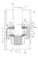
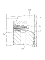
- FIG. 1 is a longitudinal sectional view showing a piston portion of a shock absorber to which a valve structure according to an embodiment of the present invention is applied.
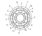
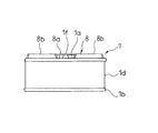
- FIG. 2 is a plan view of the piston of FIG.
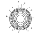
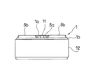
- FIG. 3 is a bottom view of the piston of FIG.
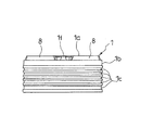
- FIG. 4 is a front view of the piston of FIG.
- FIG. 5 is a view for explaining the arrangement of the pressure side ports of the piston of FIG. 1.
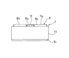
- FIG. 6 is a front view showing a state in which a piston ring is mounted on the piston of FIG.
- FIG. 7 is a front view of a piston showing a modification of the piston of FIG.
- FIG. 8 is a front view showing a state where a piston ring is attached to the piston of FIG.
- FIG. 1 is a longitudinal sectional view showing a piston portion of a shock absorber to which a valve structure according to an embodiment of the present invention is applied.
- FIG. 2 is a plan view of the piston of FIG.
- FIG. 3 is
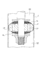
- FIG. 9 is a diagram illustrating the flow of hydraulic oil.
- FIG. 10 is a longitudinal sectional view showing a piston portion of a shock absorber to which a conventional valve structure is applied.
- FIG. 11 is a view showing a state where the compression-side leaf valve in the piston portion of FIG. 10 is bent.
- valve structure in this embodiment is applied to the piston portion of the shock absorber.
- the valve structure includes a piston 1 (valve disk) that partitions an expansion side chamber R1 (one chamber) and a pressure side chamber R2 (the other chamber) in the shock absorber, and an extension side chamber R1 and a pressure side chamber R2 provided in the piston 1.
- a plurality of expansion side ports 2 (one side port) communicating with each other, a plurality of pressure side ports 3 (the other side port) provided in the piston 1 to communicate the expansion side chamber R1 and the pressure side chamber R2, and the pressure side chamber side of the piston 1
- An annular extension side leaf valve 4 (one side leaf valve) which is stacked on the end b (the other chamber side end) and opens and closes only the extension side port 2 and an extension side chamber side end a (one chamber side end) of the piston 1
- An annular pressure-side leaf valve 5 (the other-side leaf valve) that is stacked to open and close only the pressure-side port 3 and an extension-side chamber-side end a of the piston 1 that opens from the inner peripheral side of all the pressure-side ports 3 opening.
- the expansion side chamber R1 is a chamber that is compressed when the shock absorber is extended, and the compression side chamber R2 is a chamber that is compressed when the shock absorber is contracted.
- 1 is a cross-sectional view taken along the line AA of the piston 1 shown in FIG.
- the shock absorbers are provided at, for example, a cylinder 40, a head member (not shown) that seals the upper end of the cylinder 40, a piston rod 10 that slidably penetrates the head member, and an end of the piston rod 10.
- the piston 1, the extension side chamber R1 and the pressure side chamber R2 that are two pressure chambers defined by the piston 1 and the inside of the cylinder 40, and a sealing member (not shown) for sealing the lower end of the cylinder 40
- a reservoir or an air chamber (not shown) that compensates for a volume change in the cylinder corresponding to the volume of the piston rod 10 protruding and retracting from the cylinder 40.
- the cylinder 40 is filled with a fluid, specifically, hydraulic oil.
- the shock absorber may be a double rod type instead of a single rod type.
- the piston 1 is annular, and the small-diameter portion 10 a formed at the tip of the piston rod 10 is inserted into the piston 1 to be assembled to the piston rod 10.
- the outer periphery of the piston 1 is in sliding contact with the inner periphery of the cylinder 40, whereby the piston 1 partitions the inside of the cylinder 40 into an extension side chamber R1 and a pressure side chamber R2.
- the piston 1 has a bottomed cylindrical shape, and the bottom portion 1a is provided with an insertion hole 1e through which the piston rod 10 is inserted, four extending side ports 2, and four pressure side ports 3.
- the expansion side port 2 and the pressure side port 3 respectively penetrate the bottom 1a of the piston 1 in the vertical direction that is the axial direction, and communicate the expansion side chamber R1 and the pressure side chamber R2.
- the extension side ports 2 are arranged at equal intervals along the circumferential direction in the bottom portion 1a of the piston 1
- the compression side ports 3 are also arranged at equal intervals along the circumferential direction in the bottom portion 1a of the piston 1. That is, the extension side port 2 and the pressure side port 3 are alternately arranged along the circumferential direction of the piston 1.
- a valve seat 8 surrounding each of the four pressure side ports 3 independently of each other is provided at the extension side chamber side end a of the bottom 1a of the piston 1.
- the valve seat 8 protrudes from the bottom portion 1a toward the extension side chamber side, and includes an annular portion 8a that surrounds the periphery of the insertion hole 1e and four fan-shaped seat portions 8b that are continuous with the annular portion 8a in plan view.
- a portion of the bottom portion 1a where the valve seat 8 is not provided, that is, between the seat portion 8b and the seat portion 8b along the circumferential direction has a shape recessed toward the compression side chamber. Is open.
- the bottom portion 1a is provided with protrusions 1f between the sheet portion 8b and the sheet portion 8b along the circumferential direction.
- An independent window 3a is provided at each end of the compression side port 3 on the extension side chamber side, and the seat portion 8b of the valve seat 8 surrounds the four sides of the independent window 3a.
- the extension side port 2 is arranged on the inner peripheral side from the annular zone Z (portion indicated by hatching in the drawing) in which the compression side port 3 is provided.
- the pressure side chamber side end b of the bottom 1 a of the piston 1 is provided with an annular window 7 that communicates with all the pressure side chamber side ends of the four extension ports 2. That is, the annular window 7 has an annular recess shape.
- An annular valve seat 9 is provided on the outer peripheral side of the annular window 7 and on the inner peripheral side of all the pressure side ports 3.
- the expansion side port 2 is disposed on the inner peripheral side with respect to the annular zone in which the compression side port 3 is provided. Thereby, the annular valve seat 9 can surround the annular window 7 connected to the outlet of the expansion side port 2, so that the pressure in the expansion side chamber R ⁇ b> 1 is applied uniformly over the entire circumference of the expansion side leaf valve 4 described later. be able to.
- the extension side chamber-side end a of the bottom 1 a of the piston 1 opens from the inner peripheral side of each independent window 3 a that is the end of the compression side port 3 to communicate with the extension side port 2.
- Four through holes 6 are provided.
- the through hole 6 penetrates the bottom 1 a of the piston 1 along the vertical direction in FIG. 1, which is the axial direction, and the pressure side chamber side end communicates with the annular window 7.
- the annular window 7 leads to the extension side port 2 as described above.
- the end of the through hole 6 on the side of the extension side chamber communicates with a substantially rectangular recess 13 in a plan view (FIG. 2) provided on the bottom 1 a of the piston 1.
- the recess 13 is formed so that the depth gradually increases toward the center of the rectangle, and the extension side port 2 is opened at the deepest portion.
- the recess 13 is provided on the inner peripheral side of the independent window 3a so as not to interfere with the independent window 3a, which is the bottom 1a of the piston 1.
- the depression 13 is surrounded on all sides by a seat portion 8b in the valve seat 8.
- the installation number of the extension side port 2 and the compression side port 3 is not limited to the above four, and can be set to an arbitrary number, and the through hole 6 corresponds to the installation number of the compression side port 3. What is necessary is just to provide a number. Further, the through hole 6 only needs to communicate with at least one of the plurality of extending side ports 2.
- a plurality of annular grooves 1 c are provided on the outer periphery of the cylinder portion 1 b of the piston 1.
- a synthetic resin piston ring 11 is mounted on the outer periphery of the cylindrical portion 1b.
- the piston ring 11 is mounted by being softened by heating while pressing and pressing a disc-shaped synthetic resin base material on the outer periphery of the cylindrical portion 1b of the piston 1.
- an annular recess 1d may be provided in the cylindrical portion 1b, and an annular piston ring 12 having a split may be mounted in the annular recess 1d.
- 4, 6, 7, and 8 show front views of the piston 1, the rear view, the left side view, and the right side view are the same as the front view.
- the piston 1 configured in this manner is assembled to the small diameter portion 10a of the piston rod 10.
- the piston rod 10 is arranged such that the small diameter portion 10a at the tip faces the lower side in FIG. 1 of the piston 1, and a screw portion 10b is provided at the further tip of the small diameter portion 10a. Since the upper side of the small diameter portion 10a in FIG. 1 has a larger diameter than the small diameter portion 10a, a step portion 10c is formed at the boundary between the small diameter portion 10a and the small diameter portion 10a.
- An annular pressure side leaf valve 5, an annular spacer 14, and an annular valve stopper 15 are sequentially stacked on the extension side chamber side end a which is the upper end in FIG. 1 of the piston 1.
- An annular extension side leaf valve 4 and an annular spacer 16 are sequentially stacked on the pressure side chamber side end b which is the lower end in FIG. 1 of the piston 1.
- the valve stopper 15, the spacer 14, the pressure side leaf valve 5, the piston 1, and the extension side leaf valve are arranged in order from the top in FIG. 4 and the spacer 16 are fixed to the small diameter portion 10 a of the piston rod 10.
- valve stopper 15, the spacer 14, the pressure side leaf valve 5, the piston 1, the extension side leaf valve 4, and the spacer 16 are sandwiched between the piston nut 17 and the step portion 10 c of the piston rod 10 and fixed to the piston rod 10. Is done.
- the extension-side leaf valve 4 is configured by laminating a plurality of annular plates, the inner peripheral side is fixed to the piston rod 10, and the outer periphery is allowed to bend.
- the extension-side leaf valve 4 has an outer diameter that is set so as not to close the pressure-side port 3 disposed on the outer periphery of the annular valve seat 9, so that it interferes with the pressure-side chamber side end of the pressure-side port 3. do not do.
- the extension side leaf valve 4 is pushed and bent, and away from the annular valve seat 9, the extension side port 2 is opened. .
- the compression-side leaf valve 5 is configured by laminating a plurality of annular plates in the same manner as the extension-side leaf valve 4, the inner peripheral side is fixed to the piston rod 10, and the outer periphery is allowed to bend.
- the lowermost annular plate in FIG. 1 that contacts the bottom 1 a of the piston 1 in the pressure side leaf valve 5 is seated on the valve seat 8 to close the pressure side port 3.
- the valve seat 8 is recessed between the adjacent seat portions 8b toward the center of the piston 1, and the expansion side port 2 is opened there, so the compression side leaf valve 5 closes the compression side port 3. Even then, the extension side port 2 is not blocked.
- the pressure of the pressure side chamber R2 acts on the pressure side leaf valve 5 via the pressure side port 3
- the pressure side leaf valve 5 is pushed and bent, and away from the seat portion 8b of the valve seat 8, the pressure side port 3 is opened.
- the pressure-side leaf valve 5 is not supported by the seat portion 8b when receiving the pressure of the extension side chamber R1.
- the part tends to bend in the direction of closing the extension side port 2, but since the projection 1 f is provided between the adjacent seat portions 8 b to support the compression side leaf valve 5, the flow area of the extension side port 2 is Not limited.
- the extension-side leaf valve 4 and the compression-side leaf valve 5 are configured by laminating a plurality of annular plates, and the flexural rigidity can be adjusted by the number of laminated annular plates.
- the number of stacked layers is arbitrarily set according to a damping characteristic required for the shock absorber (a characteristic of a damping force generated with respect to the piston speed of the shock absorber).
- the inner peripheral side of the compression side port 3 communicates with the expansion side port 2 through the through hole 6.
- the compression-side chamber side end of the expansion-side port 2 is closed by an expansion-side leaf valve 4 that is pressed against the piston 1 by the pressure of the compression-side chamber R2, and the opposite end of the expansion-side chamber always communicates with the expansion-side chamber R1. Therefore, as shown by the arrow in FIG. 9, a flow of hydraulic oil from the compression side port 3 through the through hole 6 and the extension side port 2 to the extension side chamber R1 occurs. Therefore, the contaminant is discharged to the through hole 6 by the above-described flow of the hydraulic oil without remaining in the gap between the pressure side leaf valve 5 and the valve seat 8 provided in the piston 1.
- the pressure-side leaf valve 5 can reliably close the pressure-side port 3, and a damping force can be generated when the shock absorber is extended. A dampening force can be stably obtained by preventing shortage.
- the depressions 13 are provided on the inner peripheral sides of the openings of all the pressure side ports 3 and the through holes 6 are opened in the depressions 13, a gap between the pressure side leaf valve 5 and the valve seat 8 in the piston 1 is provided.
- the contaminated material that has entered can be quickly guided to the through hole 6.
- the shock absorber is switched from the contraction operation to the extension operation and the compression side leaf valve 5 is bent and seated on the valve seat 8 with the restoring force, the contaminant is guided to the hole 6 along the recess 13. Therefore, it is possible to reliably prevent the contamination between the pressure side leaf valve 5 of the contaminant and the piston 1.
- the depression 13 is not in contact with the pressure side leaf valve 5, even if contaminants remain in the depression 13 when the pressure side leaf valve 5 is seated, the pressure side leaf valve 5 is prevented from being lifted from the valve seat 8. be able to.
- an annular window 7 that leads to the openings of all of the expansion side ports 2 is provided at the pressure side chamber side end b of the piston 1, and the through holes 6 are arranged to communicate with the expansion side port 2 through the annular window 7. Therefore, the through hole 6 can be formed along the axial direction with respect to the piston 1, the drilling process for drilling the through hole 6 is simplified, and the manufacturing cost of the piston to which the valve structure is applied is reduced. be able to.
- the through-hole 6 is not limited to the above-described structure, and is inclined with respect to the axial direction of the piston 1 as long as it is a structure that opens from the inner peripheral side of the compression-side port 3 and communicates with the expansion-side port 2. It may be provided, and may be bent in the middle.
- the one chamber is the expansion side chamber R1, the other chamber is the compression side chamber R2, the one side port is the expansion side port 2, the other side port is the compression side port 3, and the one side leaf valve is the expansion side leaf.
- the valve 4 was described, and the other leaf valve was described as the pressure leaf valve 5.
- one chamber is the pressure side chamber R2, the other chamber is the expansion side chamber R1, the one side port is the compression side port 3, the other side port is the expansion side port 2, and the one side leaf valve is the compression side leaf valve. 5 and the other leaf valve may be the extended leaf valve 4.
- the structure of the bottom 1a of the piston 1 is upside down in FIG.
- a petal-type valve seat that surrounds each compression side port 3 independently is provided at the expansion side chamber end a at the bottom 1a of the piston 1, and each expansion side port 2 is provided at the compression side chamber end b at the bottom 1a of the piston 1.
- the through hole is provided by opening from the inner peripheral side of the compression side port 3 and leading to the expansion side port 2, and opening through the inner peripheral side of the expansion side port 2 and leading to the compression side port 3.
- the pressure side leaf valve 5 but also the extension side leaf valve 4 can be prevented from floating.
- one of the one chamber and the other chamber is a pressure side chamber of the shock absorber
- the other of the one chamber and the other chamber is the other. It is also possible to use a reservoir for compensating the volume of the shock absorber and a valve case of a base valve that attaches the valve disc to the end of the cylinder of the shock absorber to partition the pressure side chamber and the reservoir.
- the depressions 13 are provided on the inner peripheral side of the opening of the pressure side port 3 and the through hole 6 is opened to the depression 13.
- the through hole 6 is formed in the piston without the depression 13. It is good also as a structure opened directly to the bottom part 1a.
- the valve structure of the present invention can be used for a shock absorber valve.
Landscapes
- Engineering & Computer Science (AREA)
- General Engineering & Computer Science (AREA)
- Mechanical Engineering (AREA)
- Fluid-Damping Devices (AREA)
Abstract
バルブ構造は、緩衝器内に一方室と他方室とを区画するバルブディスクと、一方室と他方室とを連通する複数の一方側ポート及び複数の他方側ポートと、一方側ポートのみを開閉する一方側リーフバルブと、他方側ポートのみを開閉する他方側リーフバルブと、を備え、一方側ポートと他方側ポートとがバルブディスクに周方向に沿って交互に配置され、すべての他方側ポートの開口の内周側から開口して一方側ポートに連通する複数の通孔を備える。
Description
本発明は、バルブ構造の改良に関する。
バルブ構造は、たとえば、車両用の緩衝器のピストン部等に適用されている。
JP2006-194335Aは、図10に示すように、緩衝器のシリンダC内に摺動自在に挿入されてシリンダC内を伸側室ERと圧側室CRとに区画するピストンPと、ピストンPに設けられ伸側室ERと圧側室CRとを連通する複数の伸側ポートEP及び圧側ポートCPと、ピストンPの圧側室側端に積層され伸側ポートEPのみを開閉する環状の伸側リーフバルブELと、ピストンPの伸側室側端に積層され圧側ポートCPのみを開閉する環状の圧側リーフバルブCLと、を備え、伸側ポートEPと圧側ポートCPとがピストンPの周方向に沿って交互に配置されたバルブ構造を開示している。
上記従来のバルブ構造を適用した緩衝器では、ピストンPが下方へ移動する収縮作動時に、図11に示すように、圧縮される圧側室CRの作動油が圧側ポートCPを介して、拡大する伸側室ERへ移動する。このとき、作動油が圧側リーフバルブCLを押して撓ませる。圧側リーフバルブCLが大きく撓むと、圧側ポートCPより内周側において、圧側リーフバルブCLとピストンPとの間に隙間が形成される。
すると、この隙間に作動油中に混入している鉄粉やダストといったコンタミナントCoが入り込む場合がある。この状態で、ピストンPが上方へ移動する緩衝器の伸長作動時に、圧側リーフバルブCLの擁みが復元力によって解消されると、圧側リーフバルブCLとピストンPとの間にコンタミナントCoが挟み込まれて、圧側ポートCPを完全に閉塞することができなくなる可能性がある。
これにより、圧側リーフバルブCLの外周がコンタミナントCoによってピストンPから浮いた状態となるので、圧縮される伸側室ER内の作動油は、伸側ポートEPだけでなく圧側ポートCPをも通過して圧側室CRへ移動するようになる。
よって、緩衝器の伸長作動時に、圧側ポートCPを通過する作動油の流れによって、ピストンPから浮いている圧側リーフバルブCLの外周が振動して、大きな異音が発生する。
緩衝器を構成する部材には切削加工を必要とするものがあり、このような部材には切削加工時に生じた鉄粉が付着したまま取り残されることがある。また、部品にダストが付着したまま取り残されることもある。したがって、コンタミナントCoの混入を完全に防止することは難しい。
JP2005-76856Aは、ピストンや、シリンダの端部に装着されるバルブケースに、コンタミナントCoを収集するための袋状やポケット状の異物溜りを設けることを開示している。しかし、この異物溜りには作動油が流れこむことができないので、コンタミナントCoを収集することは難しい。
この発明の目的は、異音の発生を防止することができるバルブ構造を提供することである。
本発明のある態様によれば、緩衝器内に一方室と他方室とを区画するバルブディスクと、バルブディスクに設けられ一方室と他方室とを連通する複数の一方側ポートと、バルブディスクに設けられ一方室と他方室とを連通する複数の他方側ポートと、バルブディスクの他方室側端に積層され一方側ポートのみを開閉する環状の一方側リーフバルブと、バルブディスクの一方室側端に積層され他方側ポートのみを開閉する環状の他方側リーフバルブと、を備え、一方側ポートと他方側ポートとがバルブディスクに周方向に沿って交互に配置されたバルブ構造であって、バルブディスクの一方室側端であってすべての他方側ポートの開口の内周側から開口して一方側ポートに連通する複数の通孔を備えるバルブ構造が提供される。
本発明の実施形態、本発明の利点については、添付された図面を参照しながら以下に詳細に説明する。
以下、本実施形態における緩衝器のバルブ構造を図に基づいて説明する。
図1~図4に示すように、本実施形態におけるバルブ構造は、緩衝器のピストン部に適用される。バルブ構造は、緩衝器内に伸側室R1(一方室)と圧側室R2(他方室)とを区画するピストン1(バルブディスク)と、ピストン1に設けられて伸側室R1と圧側室R2とを連通する複数の伸側ポート2(一方側ポート)と、ピストン1に設けられて伸側室R1と圧側室R2とを連通する複数の圧側ポート3(他方側ポート)と、ピストン1の圧側室側端b(他方室側端)に積層されて伸側ポート2のみを開閉する環状の伸側リーフバルブ4(一方側リーフバルブ)と、ピストン1の伸側室側端a(一方室側端)に積層されて圧側ポート3のみを開閉する環状の圧側リーフバルブ5(他方側リーフバルブ)と、ピストン1の伸側室側端aであって全ての圧側ポート3の開口の内周側から開口して伸側ポート2に連通される複数の通孔6と、を備える。
なお、伸側室R1とは、緩衝器が伸長作動する際に圧縮される室のことであり、圧側室R2とは、緩衝器が収縮作動する際に圧縮される室のことである。また、図1のピストン1の断面図は、図2に示したピストン1のA-A矢視断面図である。
緩衝器は、例えば、シリンダ40と、シリンダ40の上端を封止するヘッド部材(図示せず)と、ヘッド部材を摺動自在に貫通するピストンロッド10と、ピストンロッド10の端部に設けた上記ピストン1と、シリンダ40内をピストン1によって区画されて画成される2つの圧力室たる伸側室R1及び圧側室R2と、シリンダ40の下端を封止する封止部材(図示せず)と、シリンダ40から出没するピストンロッド10の体積分のシリンダ内における容積変化を補償するリザーバあるいはエア室(図示せず)と、を備える。シリンダ40内には流体、具体的には作動油が充填されている。また、緩衝器は、片ロッド型ではなく、両ロッド型であってもよい。
上記バルブ構造では、シリンダ40に対してピストン1が図1中上方に移動する場合、伸側室R1内の圧力が上昇して伸側室R1から圧側室R2へ伸側ポート2を介して作動油が移動し、この作動油の移動に伸側リーフバルブ4が抵抗を与える。反対に、シリンダ40に対してピストン1が図1中下方に移動する場合、圧側室R2内の圧力が上昇して圧側室R2から伸側室R1へ圧側ポート3を介して作動油が移動し、この作動油の移動に圧側リーフバルブ5が抵抗を与える。
以下、このバルブ構造について詳しく説明する。
図1~図4に示すように、ピストン1は環状であり、ピストンロッド10の先端に形成される小径部10aがピストン1の内方に挿通されることで、ピストンロッド10に組付けられる。また、ピストン1の外周はシリンダ40の内周に摺接しており、これによりピストン1は、シリンダ40内を伸側室R1と圧側室R2とに仕切っている。
ピストン1は、有底筒状であって、底部1aには、ピストンロッド10が挿通される挿通孔1eと、四つの伸側ポート2と、四つの圧側ポート3と、が設けられる。伸側ポート2及び圧側ポート3はそれぞれピストン1における底部1aを軸方向である上下方向に貫いており、伸側室R1と圧側室R2とを連通している。また、伸側ポート2は、ピストン1の底部1aに周方向に沿って等間隔に配置され、圧側ポート3もまたピストン1の底部1aに周方向に沿って等間隔に配置されている。つまり、伸側ポート2と圧側ポート3とは、ピストン1の周方向に沿って交互に配置されている。
ピストン1の底部1aの伸側室側端aには、四つの圧側ポート3をそれぞれ他から独立して取り囲む弁座8が備えられる。弁座8は、底部1aから伸側室側へ向けて突出しており、挿通孔1eの周囲を取り囲む環状部8aと、環状部8aに連なる平面視で扇状の四つのシート部8bとを備える。底部1aにおける弁座8が設けられていない部位、つまり、周方向に沿ったシート部8bとシート部8bとの間は、圧側室側へ凹んだ形状となっており、ここに伸側ポート2が開口している。
また、底部1aには、周方向に沿ったシート部8bとシート部8bとの間に、それぞれ突起1fが設けられている。圧側ポート3の伸側室側端には、それぞれ独立窓3aが設けられており、弁座8のシート部8bは、これら独立窓3aの四方を取り囲んでいる。また、伸側ポート2は、図5に示すように、圧側ポート3が設けられる円環状のゾーンZ(図中斜線で示した部分)よりも内周側に配置される。
図1及び図3に示すように、ピストン1の底部1aの圧側室側端bには、四つの伸側ポート2の圧側室側端の全てに連通される環状窓7が設けられる。つまり、環状窓7は環状凹部形状である。この環状窓7の外周側であって全ての圧側ポート3よりも内周側には環状弁座9が設けられる。伸側ポート2は、圧側ポート3が設けられる円環状のゾーンよりも内周側に配置される。これにより、環状弁座9によって伸側ポート2の出口に連なる環状窓7を取り囲むことができるので、後述する伸側リーフバルブ4の全周に亘って伸側室R1内の圧力を均等に作用させることができる。
図1及び図2に示すように、ピストン1の底部1aの伸側室側端aには、圧側ポート3の端部である各独立窓3aの内周側から開口して伸側ポート2に通じる四つの通孔6が設けられる。通孔6は、ピストン1の底部1aを軸方向となる図1中上下方向に沿って貫いており、その圧側室側端は、環状窓7に通じている。環状窓7は、前述のように伸側ポート2へ通じている。
また、通孔6の伸側室側端は、ピストン1の底部1aに設けた平面図(図2)で略矩形の窪み13に通じている。窪み13は、矩形の中心へ向けて深さが徐々に深くなるように形成されており最深部に伸側ポート2が開口している。窪み13は、ピストン1の底部1aであって独立窓3aに干渉しないよう独立窓3aより内周側に設けられる。さらに窪み13は、弁座8におけるシート部8bで四方が囲まれている。
なお、伸側ポート2、圧側ポート3の設置数は、上記した四つに限られるものではなく、任意の数に設定することができ、通孔6は、圧側ポート3の設置数に対応する数を設ければよい。また、通孔6は、複数ある伸側ポート2のうち少なくとも一つに連通していればよい。
図4に示すように、ピストン1の筒部1bの外周には、複数の環状溝1cが設けられる。図1、図4、図6に示すように、筒部1bの外周に合成樹脂のピストンリング11が装着される。ピストンリング11は、円盤状の合成樹脂母材をピストン1の筒部1bの外周に加圧して押し込みながら加熱軟化させて装着される。なお、これに代えて、図7および図8に示すように、筒部1bに環状凹部1dを設けておき、環状凹部1d内に割りを有する環状のピストンリング12を装着してもよい。図4、図6、図7、図8は、ピストン1の正面図を示しているが、背面図、左側面図および右側面図は、正面図と同一である。
このように構成されたピストン1は、ピストンロッド10の小径部10aに組み付けられる。ピストンロッド10は、先端の小径部10aがピストン1の図1中下方側を向くように配置され、小径部10aのさらに先端には螺子部10bが設けられる。小径部10aの図1中上方側は小径部10aより大径であるので、この小径部10aと小径部10aより上方との境に段部10cが形成される。
ピストン1の図1中上端となる伸側室側端aには、環状の圧側リーフバルブ5、環状の間座14、及び環状のバルブストッパ15が順に積層される。ピストン1の図1中下端となる圧側室側端bには、環状の伸側リーフバルブ4及び環状の間座16が順に積層される。ピストンロッド10の小径部10aに設けた螺子部10bに螺着されるピストンナット17によって、図1中上から順に、バルブストッパ15、間座14、圧側リーフバルブ5、ピストン1、伸側リーフバルブ4及び間座16がピストンロッド10の小径部10aに固定される。つまり、バルブストッパ15、間座14、圧側リーフバルブ5、ピストン1、伸側リーフバルブ4及び間座16は、ピストンナット17とピストンロッド10の段部10cとに挟持されてピストンロッド10に固定される。
伸側リーフバルブ4は、複数の環状板を積層して構成され、内周側がピストンロッド10に固定され、外周の撓みが許容される。伸側リーフバルブ4に何ら負荷が作用しない場合、伸側リーフバルブ4におけるピストン1の底部1aに接触する図1中最上段の環状板は、環状弁座9に着座して伸側ポート2を閉塞する。このとき、伸側リーフバルブ4は、その外径が、環状弁座9の外周に配置される圧側ポート3を閉塞しない程度に設定されているので、圧側ポート3の圧側室側端には干渉しない。また、伸側リーフバルブ4に伸側ポート2を介して伸側室R1の圧力が作用すると、伸側リーフバルブ4が押されて撓み、環状弁座9から離れて伸側ポート2が開放される。
圧側リーフバルブ5は、伸側リーフバルブ4と同様に、複数の環状板を積層して構成され、内周側がピストンロッド10に固定され、外周の撓みが許容される。圧側リーフバルブ5に何ら負荷が作用しない場合、圧側リーフバルブ5におけるピストン1の底部1aに接触する図1中最下段の環状板は、弁座8に着座して圧側ポート3を閉塞する。このとき、弁座8は隣接するシート部8b間においてピストン1の中心方向に向けて凹んでおり、そこに伸側ポート2が開口しているので、圧側リーフバルブ5は、圧側ポート3を閉塞しても伸側ポート2を閉塞しない。また、圧側リーフバルブ5に圧側ポート3を介して圧側室R2の圧力が作用すると、圧側リーフバルブ5が押されて撓み、弁座8のシート部8bから離れて圧側ポート3が開放される。
上述したように、ピストン1の底部1aであって弁座8の隣接するシート部8b間は凹んでいるので、圧側リーフバルブ5が伸側室R1の圧力を受けるとシート部8bによって支えられていない部位が伸側ポート2を閉塞する方向へ撓もうとするが、隣接するシート部8b間には、突起1fが突設されて圧側リーフバルブ5を支えるので、伸側ポート2の流路面積は制限されない。
なお、伸側リーフバルブ4および圧側リーフバルブ5は、複数の環状板を積層して構成され、環状板の積層枚数で撓み剛性を調節することができる。積層枚数は、緩衝器に要求される減衰特性(緩衝器のピストン速度に対して発生する減衰力の特性)に応じて任意に設定される。
このように構成されたバルブ構造では、ピストン1が図1中下方に移動する緩衝器の収縮作動時、圧縮される圧側室R2の圧力が上昇し、圧側リーフバルブ5に圧側ポート3を介して圧側室R2の圧力が作用すると、圧側リーフバルブ5の外周が撓んで圧側ポート3が開放される。これにより、作動油中に紛れ込んでいるコンタミナントが圧側ポート3を通過する作動油の流れによって、圧側リーフバルブ5とピストン1に設けた弁座8との間であって圧側ポート3よりも内周側へ入り込む可能性がある。
このとき、圧側ポート3よりも内周側は通孔6を介して伸側ポート2へ通じている。伸側ポート2における圧側室側端は、圧側室R2の圧力でピストン1に押しつけられる伸側リーフバルブ4によって閉塞され、反対の伸側室側端は、伸側室R1に常時通じている。したがって、図9の矢印に示すように、圧側ポート3から通孔6及び伸側ポート2を通過して伸側室R1へと至る作動油の流れが生じる。そのため、コンタミナントは、圧側リーフバルブ5とピストン1に設けた弁座8との間の隙間にとどまることなく、上記した作動油の流れによって、通孔6へ排出される。
以上のように本実施形態では、圧側リーフバルブ5とピストン1との間にコンタミナントが挟み込まれることを防止でき、圧側リーフバルブ5のピストン1からの浮き上がりを防止できるので、緩衝器の作動方向が切り替わった際に、圧側リーフバルブ5の外周が振動することによる大きな異音の発生を防止することができる。
また、圧側リーフバルブ5とピストン1との間にコンタミナントが挟み込まれることを防止できるので、圧側リーフバルブ5が確実に圧側ポート3を閉塞することができ、緩衝器の伸長作動時に減衰力が不足することを防止して安定して減衰力を得ることができる。
さらに、全ての圧側ポート3の開口の内周側にそれぞれ窪み13が設けられ、通孔6が窪み13に開口しているので、圧側リーフバルブ5とピストン1における弁座8との間の隙間に入り込んだコンタミナントを速やかに通孔6へ導くことができる。また、緩衝器が収縮作動から伸長作動へ切換り、圧側リーフバルブ5が撓んだ後に復元力で弁座8に着座する際にも、窪み13に沿ってコンタミナントを通孔6へ導くことができ、コンタミナントの圧側リーフバルブ5とピストン1との間での挟み込みを確実に防止することができる。さらに、窪み13は圧側リーフバルブ5とは接していないので、圧側リーフバルブ5が着座した際に窪み13にコンタミナントが残ったとしても、圧側リーフバルブ5の弁座8からの浮き上がりを防止することができる。
さらに、ピストン1の圧側室側端bに全ての伸側ポート2の開口に通じる環状窓7を設け、通孔6が環状窓7を介して伸側ポート2に連通されるように配置されるので、通孔6をピストン1に対して軸方向に沿って形成することができ、通孔6を穿設する孔開け加工が簡単となり、当該バルブ構造が適用されるピストンの製造コストを低減させることができる。なお、通孔6は、上記した構造に限定されるものではなく、圧側ポート3の内周側から開口して伸側ポート2へ通じる構造であれば、ピストン1の軸方向に対して斜めに設けられてもよいし、途中で屈曲していてもよい。
以上、本発明の実施形態について説明したが、上記実施形態は本発明の適用例の一部を示したに過ぎず、本発明の技術的範囲を上記実施形態の具体的構成に限定する趣旨ではない。
例えば、上記実施形態では、一方室を伸側室R1とし、他方室を圧側室R2とし、一方側ポートを伸側ポート2とし、他方側ポートを圧側ポート3とし、一方側リーフバルブを伸側リーフバルブ4とし、他方側リーフバルブを圧側リーフバルブ5として説明した。しかし、これに代えて、一方室を圧側室R2とし、他方室を伸側室R1とし、一方側ポートを圧側ポート3とし、他方側ポートを伸側ポート2とし、一方側リーフバルブを圧側リーフバルブ5とし、他方側リーフバルブを伸側リーフバルブ4としてもよい。この場合は、たとえば、ピストン1の底部1aの構造が図1中天地逆になる。
さらに、ピストン1の底部1aにおける伸側室側端aに各圧側ポート3を独立して取り囲む花弁型の弁座を設けるとともに、ピストン1の底部1aにおける圧側室側端bに各伸側ポート2を独立して取り囲む花弁型の弁座を設けてもよい。この場合、通孔は、圧側ポート3の内周側から開口して伸側ポート2へ通じるものと、伸側ポート2の内周側から開口して圧側ポート3へ通じるものとを設けることで、圧側リーフバルブ5の浮き上がりのみならず伸側リーフバルブ4の浮き上がりも防止することができる。
さらに、上記実施形態では、バルブ構造が緩衝器のピストン部に適用された場合について説明したが、一方室と他方室との一方を緩衝器の圧側室とし、一方室と他方室との他方を緩衝器の体積補償用のリザーバとし、バルブディスクを緩衝器のシリンダの端部に取付られて圧側室とリザーバとを区画するベースバルブのバルブケースとすることも可能である。
さらに、上記実施形態では、圧側ポート3の開口の内周側にそれぞれ窪み13が設けられ、通孔6が窪み13に開口する構造としたが、窪み13を設けることなく通孔6をピストンの底部1aに直接開口させる構造としてもよい。
本願は2011年6月8日に日本国特許庁に出願された特願2011-127924に基づく優先権を主張し、この出願の全ての内容は参照により本明細書に組み込まれる。
本発明のバルブ構造は、緩衝器のバルブに利用することができる。
Claims (4)
- 緩衝器内に一方室と他方室とを区画するバルブディスクと、
前記バルブディスクに設けられ前記一方室と前記他方室とを連通する複数の一方側ポートと、
前記バルブディスクに設けられ前記一方室と前記他方室とを連通する複数の他方側ポートと、
前記バルブディスクの他方室側端に積層され前記一方側ポートのみを開閉する環状の一方側リーフバルブと、
前記バルブディスクの一方室側端に積層され前記他方側ポートのみを開閉する環状の他方側リーフバルブと、
を備え、
前記一方側ポートと前記他方側ポートとが前記バルブディスクに周方向に沿って交互に配置されたバルブ構造であって、
前記バルブディスクの一方室側端であってすべての前記他方側ポートの開口の内周側から開口して前記一方側ポートに連通する複数の通孔を備えるバルブ構造。 - 請求項1に記載のバルブ構造であって、
前記バルブディスクの一方室側端であってすべての前記他方側ポートの開口の内周側にそれぞれ設けられる窪みを備え、
前記通孔は前記窪みに開口するバルブ構造。 - 請求項1に記載のバルブ構造であって、
前記バルブディスクの他方室側端に設けられ、すべての前記一方側ポートの他方室側の開口に通じる環状窓を備え、
前記通孔は前記環状窓を介して前記一方側ポートに連通されるバルブ構造。 - 請求項1に記載のバルブ構造であって、
前記バルブディスクは、前記緩衝器におけるシリンダ内に摺動自在に挿入されて前記シリンダ内を伸側室と圧側室とに区画するピストンであり、
前記一方室は前記伸側室であり、前記他方室は前記圧側室であるバルブ構造。
Priority Applications (3)
| Application Number | Priority Date | Filing Date | Title |
|---|---|---|---|
| EP12796069.8A EP2719916A4 (en) | 2011-06-08 | 2012-05-22 | VALVE STRUCTURE |
| US14/116,261 US9033123B2 (en) | 2011-06-08 | 2012-05-22 | Valve structure |
| CN201280021730.9A CN103534507B (zh) | 2011-06-08 | 2012-05-22 | 阀构造 |
Applications Claiming Priority (2)
| Application Number | Priority Date | Filing Date | Title |
|---|---|---|---|
| JP2011127924A JP5695507B2 (ja) | 2011-06-08 | 2011-06-08 | バルブ構造 |
| JP2011-127924 | 2011-06-08 |
Publications (1)
| Publication Number | Publication Date |
|---|---|
| WO2012169343A1 true WO2012169343A1 (ja) | 2012-12-13 |
Family
ID=47295912
Family Applications (1)
| Application Number | Title | Priority Date | Filing Date |
|---|---|---|---|
| PCT/JP2012/063070 WO2012169343A1 (ja) | 2011-06-08 | 2012-05-22 | バルブ構造 |
Country Status (6)
| Country | Link |
|---|---|
| US (1) | US9033123B2 (ja) |
| EP (1) | EP2719916A4 (ja) |
| JP (1) | JP5695507B2 (ja) |
| CN (1) | CN103534507B (ja) |
| TW (1) | TWI553242B (ja) |
| WO (1) | WO2012169343A1 (ja) |
Families Citing this family (6)
| Publication number | Priority date | Publication date | Assignee | Title |
|---|---|---|---|---|
| ITMI20130344A1 (it) * | 2013-03-07 | 2014-09-08 | Brera Cerniere Srl | Ammortizzatore a fluido, particolarmente per sportelli di elettrodomestici come forni, lavastoviglie o simili o per componenti di arredamento come antine o cassetti, ad elevata semplicita' di realizzazione. |
| JP5603965B2 (ja) * | 2013-03-25 | 2014-10-08 | カヤバ工業株式会社 | 減衰バルブ |
| US10239376B2 (en) | 2016-09-22 | 2019-03-26 | Beijingwest Industries Co., Ltd. | Hydraulic damper with an x-flow piston assembly |
| US10982633B2 (en) | 2017-07-03 | 2021-04-20 | Continental Automotive Systems, Inc. | Fuel pump solenoid assembly method |
| DE102017010876B4 (de) * | 2017-11-24 | 2023-06-01 | Günther Zimmer | Zylinder-Kolben-Einheit mit lastabhängiger Drossel |
| JP6738368B2 (ja) * | 2018-03-30 | 2020-08-12 | Kyb株式会社 | バルブシート部材、バルブ、及び緩衝器 |
Citations (2)
| Publication number | Priority date | Publication date | Assignee | Title |
|---|---|---|---|---|
| JPH0292154U (ja) * | 1989-01-10 | 1990-07-23 | ||
| JPH09144799A (ja) * | 1995-11-20 | 1997-06-03 | Toyota Motor Corp | 液圧緩衝器のバルブ構造 |
Family Cites Families (12)
| Publication number | Priority date | Publication date | Assignee | Title |
|---|---|---|---|---|
| US4615420A (en) * | 1984-01-23 | 1986-10-07 | Ford Motor Company | Piston assembly for shock absorber |
| JPS61164836U (ja) * | 1985-04-01 | 1986-10-13 | ||
| GB2226620B (en) * | 1988-10-25 | 1992-11-04 | Tokico Ltd | Hydraulic damper |
| US5332069A (en) * | 1989-08-31 | 1994-07-26 | Kayaba Kogyo Kabushiki Kaisha | Shock absorber |
| US5595269A (en) * | 1993-05-10 | 1997-01-21 | Fichtel & Sachs Ag | Vibration damper for a motor vehicle |
| JP3471438B2 (ja) * | 1993-12-06 | 2003-12-02 | 株式会社ショーワ | 緩衝器のバルブ構造 |
| JP2005076856A (ja) * | 2003-09-03 | 2005-03-24 | Honda Motor Co Ltd | ダンパ装置 |
| JP2006194335A (ja) | 2005-01-13 | 2006-07-27 | Kayaba Ind Co Ltd | バルブ構造 |
| US8069964B2 (en) | 2007-06-21 | 2011-12-06 | Tenneco Automotive Operating Company Inc. | Junction bleed |
| JP5192441B2 (ja) * | 2009-05-20 | 2013-05-08 | カヤバ工業株式会社 | 減衰バルブ |
| WO2012014618A1 (ja) * | 2010-07-28 | 2012-02-02 | カヤバ工業株式会社 | 緩衝器の減衰バルブ |
| TWM403579U (en) * | 2010-12-14 | 2011-05-11 | Yu Heng Engineering Co Ltd | Energy dissipation device having throttle valve |
-
2011
- 2011-06-08 JP JP2011127924A patent/JP5695507B2/ja active Active
-
2012
- 2012-05-22 US US14/116,261 patent/US9033123B2/en active Active
- 2012-05-22 CN CN201280021730.9A patent/CN103534507B/zh not_active Expired - Fee Related
- 2012-05-22 EP EP12796069.8A patent/EP2719916A4/en not_active Withdrawn
- 2012-05-22 WO PCT/JP2012/063070 patent/WO2012169343A1/ja active Application Filing
- 2012-05-30 TW TW101119236A patent/TWI553242B/zh not_active IP Right Cessation
Patent Citations (2)
| Publication number | Priority date | Publication date | Assignee | Title |
|---|---|---|---|---|
| JPH0292154U (ja) * | 1989-01-10 | 1990-07-23 | ||
| JPH09144799A (ja) * | 1995-11-20 | 1997-06-03 | Toyota Motor Corp | 液圧緩衝器のバルブ構造 |
Non-Patent Citations (1)
| Title |
|---|
| See also references of EP2719916A4 * |
Also Published As
| Publication number | Publication date |
|---|---|
| CN103534507B (zh) | 2015-04-01 |
| US20140076677A1 (en) | 2014-03-20 |
| US9033123B2 (en) | 2015-05-19 |
| EP2719916A1 (en) | 2014-04-16 |
| TW201307700A (zh) | 2013-02-16 |
| CN103534507A (zh) | 2014-01-22 |
| EP2719916A4 (en) | 2014-08-20 |
| TWI553242B (zh) | 2016-10-11 |
| JP5695507B2 (ja) | 2015-04-08 |
| JP2012255467A (ja) | 2012-12-27 |
Similar Documents
| Publication | Publication Date | Title |
|---|---|---|
| WO2012169343A1 (ja) | バルブ構造 | |
| JP2804071B2 (ja) | 液力式振動減衰器の減衰弁 | |
| JP7224383B2 (ja) | 緩衝器 | |
| JP2008082491A (ja) | 緩衝器のバルブ構造 | |
| JP2009014012A (ja) | 緩衝器 | |
| JP5390866B2 (ja) | バルブ | |
| JP2022132595A (ja) | 緩衝器 | |
| JP2011080573A (ja) | 緩衝器のバルブ構造 | |
| JP4898547B2 (ja) | 緩衝器のバルブ構造 | |
| JP7109293B2 (ja) | 緩衝器 | |
| JP6393572B2 (ja) | 緩衝器 | |
| JP7055076B2 (ja) | 緩衝器 | |
| JP5406672B2 (ja) | バルブ | |
| JP5307739B2 (ja) | 緩衝器のバルブ構造 | |
| JP5220560B2 (ja) | リーフバルブ | |
| JP5618415B2 (ja) | ピストン | |
| JP7055236B2 (ja) | 緩衝器 | |
| JP2008215433A (ja) | 緩衝器のバルブ構造 | |
| JP2006183775A (ja) | 油圧緩衝器 | |
| JP2011038626A (ja) | ピストン | |
| JP6949123B2 (ja) | 緩衝器 | |
| JP4932531B2 (ja) | 緩衝器のバルブ構造 | |
| JP2011158016A (ja) | 緩衝器 | |
| JP6646483B2 (ja) | バルブ | |
| JP5281326B2 (ja) | バルブ |
Legal Events
| Date | Code | Title | Description |
|---|---|---|---|
| 121 | Ep: the epo has been informed by wipo that ep was designated in this application |
Ref document number: 12796069 Country of ref document: EP Kind code of ref document: A1 |
|
| WWE | Wipo information: entry into national phase |
Ref document number: 14116261 Country of ref document: US |
|
| NENP | Non-entry into the national phase |
Ref country code: DE |