WO2012169219A1 - ダンプトラック - Google Patents
ダンプトラック Download PDFInfo
- Publication number
- WO2012169219A1 WO2012169219A1 PCT/JP2012/052242 JP2012052242W WO2012169219A1 WO 2012169219 A1 WO2012169219 A1 WO 2012169219A1 JP 2012052242 W JP2012052242 W JP 2012052242W WO 2012169219 A1 WO2012169219 A1 WO 2012169219A1
- Authority
- WO
- WIPO (PCT)
- Prior art keywords
- valve
- dump truck
- brake
- hydraulic
- branch block
- Prior art date
- Legal status (The legal status is an assumption and is not a legal conclusion. Google has not performed a legal analysis and makes no representation as to the accuracy of the status listed.)
- Ceased
Links
Images



Classifications
-
- B—PERFORMING OPERATIONS; TRANSPORTING
- B60—VEHICLES IN GENERAL
- B60T—VEHICLE BRAKE CONTROL SYSTEMS OR PARTS THEREOF; BRAKE CONTROL SYSTEMS OR PARTS THEREOF, IN GENERAL; ARRANGEMENT OF BRAKING ELEMENTS ON VEHICLES IN GENERAL; PORTABLE DEVICES FOR PREVENTING UNWANTED MOVEMENT OF VEHICLES; VEHICLE MODIFICATIONS TO FACILITATE COOLING OF BRAKES
- B60T8/00—Arrangements for adjusting wheel-braking force to meet varying vehicular or ground-surface conditions, e.g. limiting or varying distribution of braking force
- B60T8/32—Arrangements for adjusting wheel-braking force to meet varying vehicular or ground-surface conditions, e.g. limiting or varying distribution of braking force responsive to a speed condition, e.g. acceleration or deceleration
- B60T8/34—Arrangements for adjusting wheel-braking force to meet varying vehicular or ground-surface conditions, e.g. limiting or varying distribution of braking force responsive to a speed condition, e.g. acceleration or deceleration having a fluid pressure regulator responsive to a speed condition
- B60T8/36—Arrangements for adjusting wheel-braking force to meet varying vehicular or ground-surface conditions, e.g. limiting or varying distribution of braking force responsive to a speed condition, e.g. acceleration or deceleration having a fluid pressure regulator responsive to a speed condition including a pilot valve responding to an electromagnetic force
- B60T8/3605—Arrangements for adjusting wheel-braking force to meet varying vehicular or ground-surface conditions, e.g. limiting or varying distribution of braking force responsive to a speed condition, e.g. acceleration or deceleration having a fluid pressure regulator responsive to a speed condition including a pilot valve responding to an electromagnetic force wherein the pilot valve is mounted in a circuit controlling the working fluid system
-
- B—PERFORMING OPERATIONS; TRANSPORTING
- B60—VEHICLES IN GENERAL
- B60T—VEHICLE BRAKE CONTROL SYSTEMS OR PARTS THEREOF; BRAKE CONTROL SYSTEMS OR PARTS THEREOF, IN GENERAL; ARRANGEMENT OF BRAKING ELEMENTS ON VEHICLES IN GENERAL; PORTABLE DEVICES FOR PREVENTING UNWANTED MOVEMENT OF VEHICLES; VEHICLE MODIFICATIONS TO FACILITATE COOLING OF BRAKES
- B60T17/00—Component parts, details, or accessories of power brake systems not covered by groups B60T8/00, B60T13/00 or B60T15/00, or presenting other characteristic features
- B60T17/04—Arrangements of piping, valves in the piping, e.g. cut-off valves, couplings or air hoses
-
- B—PERFORMING OPERATIONS; TRANSPORTING
- B60—VEHICLES IN GENERAL
- B60T—VEHICLE BRAKE CONTROL SYSTEMS OR PARTS THEREOF; BRAKE CONTROL SYSTEMS OR PARTS THEREOF, IN GENERAL; ARRANGEMENT OF BRAKING ELEMENTS ON VEHICLES IN GENERAL; PORTABLE DEVICES FOR PREVENTING UNWANTED MOVEMENT OF VEHICLES; VEHICLE MODIFICATIONS TO FACILITATE COOLING OF BRAKES
- B60T17/00—Component parts, details, or accessories of power brake systems not covered by groups B60T8/00, B60T13/00 or B60T15/00, or presenting other characteristic features
- B60T17/18—Safety devices; Monitoring
-
- B—PERFORMING OPERATIONS; TRANSPORTING
- B60—VEHICLES IN GENERAL
- B60T—VEHICLE BRAKE CONTROL SYSTEMS OR PARTS THEREOF; BRAKE CONTROL SYSTEMS OR PARTS THEREOF, IN GENERAL; ARRANGEMENT OF BRAKING ELEMENTS ON VEHICLES IN GENERAL; PORTABLE DEVICES FOR PREVENTING UNWANTED MOVEMENT OF VEHICLES; VEHICLE MODIFICATIONS TO FACILITATE COOLING OF BRAKES
- B60T8/00—Arrangements for adjusting wheel-braking force to meet varying vehicular or ground-surface conditions, e.g. limiting or varying distribution of braking force
- B60T8/32—Arrangements for adjusting wheel-braking force to meet varying vehicular or ground-surface conditions, e.g. limiting or varying distribution of braking force responsive to a speed condition, e.g. acceleration or deceleration
- B60T8/34—Arrangements for adjusting wheel-braking force to meet varying vehicular or ground-surface conditions, e.g. limiting or varying distribution of braking force responsive to a speed condition, e.g. acceleration or deceleration having a fluid pressure regulator responsive to a speed condition
- B60T8/36—Arrangements for adjusting wheel-braking force to meet varying vehicular or ground-surface conditions, e.g. limiting or varying distribution of braking force responsive to a speed condition, e.g. acceleration or deceleration having a fluid pressure regulator responsive to a speed condition including a pilot valve responding to an electromagnetic force
- B60T8/3615—Electromagnetic valves specially adapted for anti-lock brake and traction control systems
- B60T8/3675—Electromagnetic valves specially adapted for anti-lock brake and traction control systems integrated in modulator units
- B60T8/368—Electromagnetic valves specially adapted for anti-lock brake and traction control systems integrated in modulator units combined with other mechanical components, e.g. pump units, master cylinders
- B60T8/3685—Electromagnetic valves specially adapted for anti-lock brake and traction control systems integrated in modulator units combined with other mechanical components, e.g. pump units, master cylinders characterised by the mounting of the modulator unit onto the vehicle
Definitions
- the present invention relates to a dump truck, and more particularly to an improvement in the layout of a brake equipment box.
- a brake hydraulic pressure corresponding to a pedal operation of a service brake (foot brake) is distributed to the left and right by a branch block and acts on a wet multi-plate brake mounted on each of the left and right traveling wheels. It has become.
- a time lag will occur at the beginning of the left and right brakes, and one side effect will occur. Will shake.
- the branch block for the front brake is arranged in the left and right center of the vehicle body at the rear of the platform, and the left and right pipe lengths are made equal.
- the exhaust pipe is covered with a disaster prevention cover.
- hydraulic equipment such as a branch block is accommodated in a box-shaped member such as a brake equipment box.
- the gap of the brake equipment box is covered with a rubber plate, a drain hose is provided in the brake equipment box, or the brake equipment box leaks so that the scattered hydraulic oil does not leak outside from the brake equipment box.
- An enclosing portion is provided on the disaster prevention cover so that the operating oil does not flow forward or left and right to reach the exhaust pipe.
- An object of the present invention is to provide a dump truck that can eliminate the need for a complicated disaster prevention structure while preventing a time lag from occurring in the effectiveness of the left and right brakes.
- the dump truck according to the first aspect of the present invention provides traveling wheels disposed on both sides of the vehicle body frame in the vehicle width direction, service brakes provided on the traveling wheels on both sides, and hydraulic oil for generating braking for each service.
- a branch block that branches and outputs to the brake, the branch block being provided offset from the center in the vehicle width direction in the vehicle width direction, and a hydraulic line connecting the branch block and each service brake is Further, it is arranged through substantially the center in the vehicle width direction, and is arranged in parallel between the branch block and the center.
- the dump truck according to the second aspect of the present invention is characterized in that a cab provided on one end side in the vehicle width direction is provided, and the branch block is provided behind the cab.
- a service brake valve and a retarder valve that adjust the supply of the hydraulic oil to the service brake, the hydraulic pressure of the hydraulic oil from the service brake valve, and the hydraulic pressure of the hydraulic oil from the retarder valve
- a shuttle valve that outputs hydraulic oil having a high hydraulic pressure, the shuttle valve is provided behind the cab, and a hydraulic line that connects the shuttle valve, the service brake valve, and the retarder valve, It is disposed substantially through the center in the vehicle width direction, and is juxtaposed with a hydraulic line connecting the branch block and each service brake.
- the shuttle valve and the branch block are housed in a box-shaped brake device box.
- the dump truck according to a fifth aspect of the present invention is characterized in that an electromagnetic valve for an exhaust brake is accommodated in the brake equipment box.
- the dump truck according to a sixth aspect of the invention is characterized in that an ABS cancel valve and an ABS valve for an ABS (Antiskid Brake System) are accommodated in the brake equipment box.
- the hydraulic device related to the brake such as the branch block is offset from the center in the vehicle width direction, so that the exhaust pipe, the exhaust turbocharger, the high-temperature equipment such as the engine, and the disaster prevention cover that covers it. Therefore, there is no fear that the hydraulic oil scattered from such hydraulic equipment falls on the high temperature equipment. Therefore, the conventional complex disaster prevention structure can be eliminated around the disaster prevention cover.
- the hydraulic line connecting the branch block and the service brake is arranged in parallel through the approximate center in the vehicle width direction, the length of the hydraulic line for the left and right service brakes can be made substantially the same. The time lag until the braking force is generated can be reduced, and the one-side effect of the brake can be suppressed.
- traveling wheels and the like are arranged below the cab arranged at one end side in the vehicle width direction, and there are no high temperature equipment or parts.
- the hydraulic line connecting the shuttle valve, the service brake valve, and the retarder valve is also arranged side by side through the approximate center in the vehicle width direction, so that the one-side effect of the brake can be prevented more reliably. it can.
- hydraulic equipment such as a shuttle valve, a branch block, an exhaust brake electromagnetic valve, an ABS cancel valve, an ABS valve, etc. is used in the brake equipment box.
- the aggregated joint portions may be collectively covered with a disaster prevention cover or the like, and it is not necessary to individually install the disaster prevention cover or the like, and the structure can be further simplified.
- these hydraulic devices are covered with the brake device box, the appearance can be improved, and the weather resistance and durability of the hydraulic devices can be improved.
- FIG. 1 is a perspective view showing an entire dump truck according to an embodiment of the present invention.
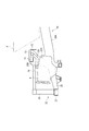
- the side view which is the principal part of a dump truck and shows an exhaust pipe position.
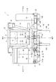
- the top view which shows typically the hydraulic path for the principal parts of a dump truck and a front brake.
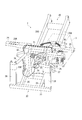
- the perspective view which shows arrangement
- the perspective view which shows the principal part of a dump truck.
- the perspective view which shows the support state of the brake equipment box at the time of transport.
- the front / rear / left / right direction means the same direction as the front / rear / left / right direction in a state where the driver is seated on the driver's seat in the cab 3.
- the left-right direction and the vehicle width direction are synonymous.
- FIG. 1 is a perspective view showing the entire dump truck 1 according to the present embodiment.
- a large dump truck 1 includes a body frame 2, and a cab 3 on which a driver enters is mounted on the left end side of the front upper part of the body frame 2.
- a vessel 4 for loading loads such as rocks and earth and sand is rotatably provided by expansion and contraction of a hoist cylinder (not shown).
- the vehicle body frame 2 has four traveling wheels 5 (front wheel 5A, rear wheel 5B) attached to the front, rear, left and right.
- the traveling wheels 5 are driven by a driving force from an engine 6 mounted on the front side of the body frame 2.
- the front side of the body frame 2 is provided with ladders 7 on the right and left for raising and lowering between the cab 3 arranged at a high place and the ground.
- an area on the right side of the cab 3 is a platform 8 that performs maintenance of the engine 6 and the like from above, and is also a walkable area around the cab 3 including the platform 8.
- a handrail 9 is attached.
- FIG. 2 shows a side view of the main part on the front side of the body frame 2
- FIG. 3 shows a plan view thereof.
- the center in the vehicle width direction is indicated by a one-dot chain line C.
- the vehicle body frame 2 is integrated with a main frame 20 having a pair of left and right side frames 20 ⁇ / b> A and a square frame-shaped frame 20 ⁇ / b> B standing in front of the left and right side frames 20 ⁇ / b> A.
- a front support 22 attached to the vehicle.
- the frame-type frame 20B of the main frame 20 includes an upper cross member 21 installed on the left and right.
- a left side bracket 23 extending to the left side and a right side bracket 24 extending to the right side are provided immediately behind the upper cross member 21.
- the front support 22 includes left and right lower side members 25 positioned on the extension of each side frame 20A, a cylindrical upper side member 26 positioned above each lower side member 25, and each lower side member 25.
- the front cross member 27 is erected on the left and right sides between the front ends of the upper side member 26, and the radiator support 28 is erected on the upper and lower sides between the front ends of the lower side member 25 and the upper side member 26.
- the engine 6 is accommodated in the front support 22, and the engine hood 14 that covers the engine 6 is fixed to the upper side member 26 and the like at the upper part of the front support 22.
- the back side of the cab 3 is placed via the left and right cab mounts 31, and the rear part of the fender 11 (FIGS. 1 and 6) covering the upper side of the left front wheel 5A is attached. It is done. That is, in the dump truck 1, the cab 3 is located above the front wheel 5A.
- the rear side portion of the fender 11 that covers the upper side of the right front wheel 5 ⁇ / b> A is also attached to the right side bracket 24.
- an exhaust pipe 12 connected to a pair of exhaust pipes 12A from the engine 6 is arranged to extend rightward from a rear position of the upper cross member 21.
- a part of the exhaust pipe 12 protrudes above the right side bracket 24 through the opening portion 24 ⁇ / b> A of the right side bracket 24.
- the projecting tip of the exhaust pipe 12 is a communication opening 12B that opens upward, and when the vessel 4 is lowered, the base end side opening of an exhaust communication passage (not shown) provided in the vessel 4 is provided. Communicated with.
- the exhaust gas from the engine 6 flows into the proximal end side of the exhaust pipe 12 through the pair of exhaust pipes 12A, then flows out from the communication opening 12B on the distal end side, is sent into the exhaust communication path of the vessel 4, and warms the vessel 4. .
- Such an exhaust pipe 12 is heated by exhaust gas and becomes high temperature.
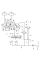
- FIG. 3 also schematically shows hydraulic oil piping paths for the service brakes 49 and 51 provided on the left and right front wheels 5A.
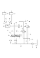
- FIG. 4 shows a hydraulic circuit of such a piping path.
- a service brake valve (hereinafter referred to as a brake valve) 33 outputs hydraulic oil for causing braking to the service brakes 49 and 51 of the front wheel 5A and the service brake of the rear wheel 5B. It is.
- the hydraulic oil is supplied from the hydraulic oil tank 34 to the brake valve 33 by the hydraulic pump 35.
- the hydraulic pressure due to such hydraulic oil is accumulated in each accumulator 37 provided in a hydraulic line 36 from the hydraulic pump 35 to the brake valve 33.
- the pedal 32 When the pedal 32 is operated to apply the brake, the position of the input / output port on the brake valve 33 is switched, and the hydraulic fluid of the pressure accumulated in the accumulator 37 is input to one side of the shuttle valve 39 via the hydraulic line 38. Supplied to the port.
- a hydraulic line 41 branches from a hydraulic line 36 from the hydraulic pump 35 and is connected to a retarder proportional control valve (hereinafter referred to as a retarder valve) 42.
- a retarder valve 42 causes the hydraulic line 43 to the other input port of the shuttle valve 39 and the drain 44 to the hydraulic oil tank 34 to communicate with each other.
- the hydraulic oil from the hydraulic line 41 is supplied to the shuttle valve 39 through the hydraulic line 43 according to the magnitude of the signal.
- the shuttle valve 39 selects the higher hydraulic pressure from the hydraulic pressure from the brake valve 33 supplied through the hydraulic line 38 and the hydraulic pressure from the retarder valve 42 supplied through the hydraulic line 43, and the hydraulic oil of this hydraulic pressure is selected. Is output from the output port to the branch block 46 through the hydraulic line 45.
- the branch block 46 branches the hydraulic oil from the hydraulic line 45 to the hydraulic lines 47 and 48.
- the hydraulic line 47 is connected to a service brake 49 for the left front wheel 5A via a slack adjuster 47S.
- the hydraulic line 48 is connected to a service brake 51 for the right front wheel 5A via a slack adjuster 48S.
- the branch block 46 and the shuttle valve 39 are accommodated in a brake device box 70 placed behind the cab 3.
- FIG. 5 shows the arrangement of hydraulic devices for braking.
- the brake valve 33 having the pedal 32 is provided on the floor portion inside the cab 3.
- the hydraulic oil tank 34 is disposed below the right side frame 20A.
- a transmission 10 is disposed behind the engine 6, a PTO (power take-off device) is provided on the front side of the transmission 10, and a hydraulic pump 35 is attached to the PTO. That is, the hydraulic pump 35 is disposed between the engine 6 and the transmission 10.
- the accumulator 37 for the service brakes 49 and 51 is attached to the left side of the frame-type frame 20B.
- the retarder valve 42 is attached to the right side frame 20A.
- the retarder lever 18 is provided in the steering column shown in FIG.
- a retarder signal corresponding to the amount of operation of the retarder lever 18 is generated by a controller (not shown) and output to the solenoid of the retarder valve 42 to control the opening degree of the retarder valve 42.
- a controller not shown
- FIG. 6 and 7 are a perspective view and a plan view showing the main part of the dump truck 1.
- FIG. 6 and 7, the upper surface of the upper cross member 21 is located behind the engine hood 14. Further, an inverted L-shaped disaster prevention cover 15 that covers the exhaust pipe 12 from above and behind is provided on the rear side of the upper cross member 21.
- the upper surface of the disaster prevention cover 15, the upper surface of the upper cross member 21, and the upper surface of the engine hood 14 are substantially flush and flat, and the platform 8 is formed at this portion.
- a battery box 16 (not shown in FIG. 7) in which a battery is built is installed above with a predetermined height.
- the brake equipment box is attached to the upper part of the disaster prevention cover 15, but in this embodiment, the brake equipment box 70 is attached to the left side bracket 23 at the rear part of the cab 3.
- the brake equipment box 70 is attached to the left side bracket 23 at the rear part of the cab 3.
- a shuttle valve 39 and a branch block 46 are installed in the brake device box 70. 2 to 4, one end of hydraulic lines 38 and 43 is connected to the shuttle valve 39, and one end of hydraulic lines 47 and 48 is connected to the branch block 46.
- These hydraulic lines 38, 43, 47, 48 are arranged along the left-right direction using the space below the battery box 16, and are located approximately at the center in the vehicle width direction (see the one-dot chain line C in FIG. 7). It extends to the rear side through and is connected to the shuttle valve 39 or the branch block 46 in the brake equipment box 70 attached to the rear of the cab 3.
- the hydraulic line 38 includes a flexible hose 38A having one end connected to the shuttle valve 39 and a metal tube 38B having one end connected to the other end of the hose 38A.
- the hose 38 ⁇ / b> A and the tube 38 ⁇ / b> B are connected by a first joint 61 located on the base end side of the left side bracket 23.
- One end side of the tube 38B is held by an inverted L-shaped holding bracket 62 with a U-bolt, and the central portion passes through the center in the vehicle width direction and is another holding bracket 63 attached to the lower surface of the support base 17 of the battery box 16.
- the other end side is connected to another tube 38 ⁇ / b> C at the second joint portion 64 by being bent to the left below the battery box 16.
- the tube 38 ⁇ / b> C constitutes a part of the hydraulic line 38 and is finally connected to a brake valve 33 provided on the floor of the cab 3.
- the hydraulic line 43 includes a flexible hose 43A having one end connected to the shuttle valve 39 and a metal tube 43B having one end connected to the other end of the hose 43A.
- a flexible hose 43A having one end connected to the shuttle valve 39 and a metal tube 43B having one end connected to the other end of the hose 43A.
- One end side of the tube 43B is held by the holding bracket 62, and the central portion is passed through the center in the vehicle width direction and is held by the holding bracket 63 with a U-bolt.
- the side is connected to another tube 43 ⁇ / b> C at the third joint portion 65.
- the tube 43C constitutes a part of the hydraulic line 43, and is finally connected to a retarder valve 42 (FIGS. 3 and 4) disposed substantially opposite to the brake valve 33 in the vehicle width direction. .
- the hydraulic lines 47 and 48 connected to the branch block 46 are flexible hoses 47A and 48A having one end connected to the branch block 46, and a metal having one end connected to the other ends of the hoses 47A and 48A.
- the tubes 47 ⁇ / b> B and 48 ⁇ / b> B are formed, and are connected to each other by the first joint 61.
- One end sides of the tubes 47B and 48B are held by the holding bracket 62, and the central portion passes through the center in the vehicle width direction and is held by the holding bracket 63 with a U bolt.
- the central portion of the tube 47B is bent to the left below the battery box 16, and the other end is connected to another tube 47C at the second joint portion 64.
- the tube 47C constitutes a part of the hydraulic line 47 and is finally connected to the service brake 49 (FIGS. 3 and 4) for the left front wheel 5A.
- the central portion of the tube 48B is bent to the right below the battery box 16, and the other end side is connected to another tube 48C at the third joint portion 65.
- the tube 48C constitutes a part of the hydraulic line 48 and is finally connected to the service brake 51 (FIGS. 3 and 4) for the right front wheel 5A.
- the hydraulic lines 38, 43, 47, 48 pass through the center in the vehicle width direction, so that the tubes 38B, 43B, 47B, 48B constituting them are arranged side by side and attached to the common holding brackets 62, 63. It is done.
- the tubes 38B, 43B, 47B, and 48B pass above the disaster prevention cover 15, that is, near the upper portion of the exhaust pipe 12 that is at a high temperature.
- the tubes 38B, 43B, 47B, and 48B are joined on the way. Since there is no continuous tube, there is no portion where the hydraulic oil leaks above the disaster prevention cover 15.
- the first to third joint portions 61, 64, 65 are shifted from the front, back, left, and right of the disaster prevention cover 15, and in the unlikely event that such first to third joint portions 61, 64, 65 are used. Even if the hydraulic oil scatters, it is difficult to fall on the disaster prevention cover 15.
- the first joint portion 61 is covered with the anti-scattering cover 66 attached to the holding bracket 62, even if the hydraulic oil should be ejected, the first joint portion 61 collides with the anti-scattering cover 66 and becomes a high temperature component. Will drop in the downward direction, and will not scatter to the disaster prevention cover 15 side.
- the second and third joint portions 64 and 65 are also directly covered by the support base 17, and the support base 17 functions as a scattering prevention cover, and also the second and third joint portions 64 and 65. The hydraulic oil is prevented from scattering to the disaster prevention cover 15 side by the shielding plates 19 erected on the vehicle body center side.
- the hydraulic lines 38, 43, 47, and 48 pass through the center in the vehicle width direction, so that the lengths of the hydraulic lines 47 and 48 can be made substantially the same, and a time lag can be prevented from occurring in the effectiveness of the left and right brakes. Therefore, it is possible to prevent the vehicle body from being shaken due to the single effect. Furthermore, since the tubes 8B, 43B, 47B, 48B of the hydraulic lines 38, 43, 47, 48 are arranged side by side, they can be fixed together using the common holding brackets 62, 63, and the assembly work can be performed. Easy to do.
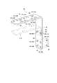
- FIG. 8 shows a brake device box 70.
- the brake device box 70 is made of sheet metal, and includes a box body 71 fixed to the left side bracket 23 and a cover 72 that covers the box body 71.
- the box body 71 includes a substantially rectangular bottom 73 in plan view, a short side wall 74 standing up along two adjacent sides of the bottom 73, and a long side wall 75.
- the bottom 73 is provided with four bolt insertion holes 76, and the box body 71 is fixed to the left side bracket 23 by bolts inserted through these holes.
- the bottom portion 73 is provided with four other bolt insertion holes 77, and the shuttle valve 39 and the branch block 46 are attached to the bottom portion 73 by bolts inserted into the bolt insertion holes 77 from the back side. .
- the bottom 73 is provided with an extension 78 on the side facing the short side wall 74, and the extension 78 is provided with a hose holding part 79 at a higher position.
- the hose holding portion 79 is provided with a bolt insertion hole 81, and a clamp for holding the hoses 38A, 43A, 47A, 48A is bolted.
- mounting bosses 82 are provided on the bottom 73. Of these, four mounting bosses 82A are mounted with electromagnetic valves 100 for exhaust brake hydraulic actuators provided on demand. A clamp for holding a hydraulic hose connected to the electromagnetic valve 100 is bolted to the remaining two mounting bosses 82B.
- the short side wall 74 is provided with a pair of connector brackets 83 and mounting bosses 84, and the long side wall 75 is provided with a pair of bolt insertion holes 85.
- the signal cable 86 (FIGS. 6 and 7) for the electromagnetic valve 100 is drawn into the box body 71 and provided at the tip of the signal cable 86.
- a male connector is attached to the connector bracket 83, and a blind member is inserted into each connector.
- the female connector of the signal cable extending from the electromagnetic valve 100 is connected to the male connector of the signal cable 86.
- the A clamp that holds such a signal cable 86 is bolted to the mounting boss 84 and the bolt insertion hole 85.
- the cover 72 includes a ceiling part 87, a short side wall part 88, and a long side wall part 89, and is fixed to the box main body 71 with four bolts from above and in the horizontal direction.
- the ceiling part 87, the short side wall part 88, and the long side wall part 89 of the cover 72 are opposed to the bottom part 73, the short side wall part 74, and the long side wall part 75 of the box body 71, respectively. It is formed in a box shape as a whole.
- an opening 91 is provided in the short side wall 88 of the cover 72, and the hoses 38 ⁇ / b> A, 43 ⁇ / b> A, 47 ⁇ / b> A, 48 ⁇ / b> A and the signal cable 86 are disposed through the opening 91.
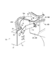
- FIG. 9 shows an inverted L-shaped holding bracket 62.
- the holding bracket 62 has a vertical portion 92 that is long in the vertical direction and a horizontal portion 93 that extends horizontally from the upper end thereof.
- the vertical portion 92 is provided with a plurality (six in this embodiment) of bolt insertion holes 94.
- the pair of bolt insertion holes 94A along the vertical direction on the lower side is used for bolting the holding bracket 62 itself to a rectangular mounting boss 95 provided in the main frame 20.
- a pair of bolt insertion holes 94B adjacent to the bolt insertion holes 94A are used to attach a support bracket 112 described later shown in FIG.
- the pair of bolt insertion holes 94C along the horizontal direction on the upper side is used to add and fix the holding bracket 110 indicated by a two-dot chain line.
- a hose connected to the electromagnetic valve 100 is held by a U bolt.
- a back nut 96 is provided on the back surface of the vertical portion 92 corresponding to the bolt insertion holes 94B and 94C.
- the horizontal portion 93 is also provided with a plurality (10 in this embodiment) of bolt insertion holes 97.
- the eight bolt insertion holes 97A are for holding the tubes 38B, 43B, 47B, and 48B with U bolts, and the male screw portion of the U bolt is inserted from below.
- Such bolt insertion holes for U-bolts are also provided in the holding bracket 110, although not shown with reference numerals.
- the remaining pair of bolt insertion holes 97 ⁇ / b> B is used for attaching the above-described scattering prevention cover 66. Therefore, a back nut 98 corresponding to the bolt insertion hole 97 ⁇ / b> B is provided on the back surface of the horizontal portion 93.
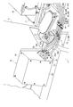
- FIG. 10 shows the support bracket 112.
- the support bracket 112 is a member that supports the brake device box 70 on the main frame 20 of the vehicle body frame 2 (the holding bracket 62 attached thereto) in a cantilever state.
- the cab 3 is once removed from the vehicle body frame 2 together with the left side bracket 23 due to transport restrictions, transported by a trailer or the like in a semi-finished state, and reassembled at the transport destination.
- the brake equipment box 70 is attached to the left side bracket 23 as it is during transportation, the hoses 38A, 43A, 47A, 48A and the like need to be removed from the shuttle valve 39 and the branch block 46 in the brake equipment box 70 instead. In addition, it takes time and labor to reconnect after transportation or to close the end when it is pulled out. Therefore, the brake device box 70 is removed from the left side bracket 23 as it is and is supported by the support bracket 112, so that work efficiency is improved. Since the hoses 38A, 43A, 47A, and 48A have flexibility, even if the position of the brake device box 70 is shifted, they can follow without any problem.
- the brake device box 70 can be easily attached to the distal end of the support bracket 112 by using the bolt insertion hole 76 that is inherent to the brake device box 70, and the base end thereof is attached to the holding bracket 62 as described above. It is fixed with bolts.
- the brake equipment box 70 is also removed from the support bracket 112 and attached to the left side bracket 23 at the rear of the cab 3, so that the support bracket 112 becomes unnecessary and is disposed of as appropriate.
- FIG. 11 shows a hydraulic circuit having specifications in which an ABS is mounted.
- an ABS cancel valve 121 is provided in the hydraulic line 45 on the output side of the shuttle valve 39.
- the hydraulic line 45 is divided into a hydraulic line 45A and a hydraulic line 45B on the output side of the ABS cancel valve 121.
- the hydraulic line 45A is connected to the branch block 46A, and the hydraulic line 45B is connected to the branch block 46B.
- the pair of hydraulic lines 471 and 481 branched by the branch block 46A are connected to the slack adjusters 47S and 48S through the shuttle valves 122 and 123 and the hydraulic lines 47 and 48, respectively.
- the hydraulic lines 471 and 482 are provided with ABS valves 124 and 125.
- the hydraulic lines 472 and 482 branched by the branch block 46B are connected to the slack adjusters 47S and 48S through the shuttle valves 122 and 123 and the hydraulic lines 47 and 48, respectively.
- no ABS valve is provided in the hydraulic lines 472 and 482.
- the ABS cancel valve 121 is in the OFF state, the hydraulic oil from the shuttle valve 39 is supplied through the hydraulic line 45A, and the ABS is activated by the action of the ABS valves 124 and 125. be able to.
- the ABS is canceled by the ABS cancel valve 121, the hydraulic oil from the shuttle valve 39 is supplied through the hydraulic line 45B, and the same state as in the above-described embodiment is obtained.
- ABS cancel valve 121, the pair of branch blocks 46A and 46B, the shuttle valves 122 and 123, the ABS valves 124 and 125, and the like are accommodated in the brake device box 70. Accordingly, as shown in FIG. 12, such a brake equipment box 70 has a larger accommodation volume and a larger outer shape than the brake equipment box 70 described in the above embodiment. Other configurations are the same as those of the above-described embodiment. In FIGS. 10 and 12, the same reference numerals are given to the same functional members, parts, and the like as in the above-described embodiment.
- the object of the present invention can be achieved. Further, the electromagnetic valve 100 for the exhaust brake may be accommodated in the brake equipment box 70. During transportation, the brake equipment box 70 is removed from the left side bracket 23 and is attached to the main frame 20 or the like by the support bracket 112. It may be supported.
- the exhaust pipe has been described as the high-temperature equipment, but the high-temperature equipment may be an engine body, an exhaust turbine supercharger, or the like.
- the present invention can be suitably used for the rigid dump truck described in the above embodiment.
Landscapes
- Engineering & Computer Science (AREA)
- Physics & Mathematics (AREA)
- Transportation (AREA)
- Mechanical Engineering (AREA)
- Electromagnetism (AREA)
- Fluid Mechanics (AREA)
- Valves And Accessory Devices For Braking Systems (AREA)
Abstract
Description
第5発明に係るダンプトラックでは、前記ブレーキ機器ボックスには、排気ブレーキ用の電磁バルブが収容されていることを特徴とする。
第6発明に係るダンプトラックでは、前記ブレーキ機器ボックスには、ABS(Antiskid Brake System ; Antilock Brake System)用のABSキャンセルバルブおよびABSバルブが収容されていることを特徴とする。
また、分岐ブロックとサービスブレーキとを接続する油圧ラインは、車幅方向の略中央を通って並設されているため、左右のサービスブレーキに対する油圧ラインの長さを略同じにでき、各サービスブレーキでの制動力が生じるまでのタイムラグを小さくできて、ブレーキの片効きを抑制できる。
また、それらの油圧機器がブレーキ機器ボックスで覆われるので、外観を良好にできるうえ、油圧機器の耐候性、耐久性を向上させることができる。
なお、以下の説明において、前後左右方向とは、運転者がキャブ3内の運転席に着座した状態における前後左右方向と同一方向をいう。また、左右方向と車幅方向とは同義である。
図1において、大型のダンプトラック1は、車体フレーム2を備え、車体フレーム2前方上部の左端側には、運転者が乗り込むキャブ3が搭載され、車体フレーム2の後方上部には、例えば採掘された岩石や土砂等の積載物を積載するベッセル4が、図示しないホイストシリンダの伸縮により回動自在に設けられている。
図2、図3において、車体フレーム2は、左右一対のサイドフレーム20A、およびこれらの前方に立設された四角枠状の枠型フレーム20Bを有するメインフレーム20と、メインフレーム20の前方に一体に取り付けられたフロントサポート22とを備えている。
このような排気管12は、排気ガスによって加熱され、高温となる。
図3、図4において、サービスブレーキバルブ(以下、ブレーキバルブと称する)33は、制動を生じさせるための作動油を前輪5Aのサービスブレーキ49,51、および後輪5Bのサービスブレーキに出力するものである。
図5に示すように、ペダル32を有したブレーキバルブ33は、キャブ3内部のフロア部分に設けられている。作動油タンク34は、右側のサイドフレーム20Aの下方側に配置されている。また、エンジン6の後方にはトランスミッション10が配置され、トランスミッション10の前側にはPTO(動力取出装置)が設けられ、このPTOに油圧ポンプ35が取り付けられている。つまり、油圧ポンプ35は、エンジン6とトランスミッション10との間に配置されている。サービスブレーキ49,51用のアキュムレータ37は、枠型フレーム20Bの左側方に取り付けられている。リターダバルブ42は、右側のサイドフレーム20Aに取り付けられている。
図6、図7において、エンジンフード14の後方には、上側クロスメンバー21の上面が位置している。また、上側クロスメンバー21の後方側には、排気管12を上方および背後から覆う逆L字状の防災カバー15が設けられている。防災カバー15の上面、上側クロスメンバー21の上面、およびエンジンフード14の上面は略面一でフラットであり、この部分でプラットホーム8が形成されている。プラットホーム8の前記上側クロスメンバー21に対応した位置には、内部にバッテリが内蔵されたバッテリボックス16(図7では図示省略)が所定高さだけ間を空けて上方に設置されている。
これに対してチューブ48Bの中央部分は、バッテリボックス16の下方で右側に折曲し、他端側が別のチューブ48Cに第3継ぎ部65にて接続される。チューブ48Cは、油圧ライン48の一部を構成しており、最終的に右側の前輪5A用のサービスブレーキ51(図3、図4)に接続される。
さらに、油圧ライン38,43,47,48の各チューブ8B,43B,47B,48Bが並べて配置されていることで、それらを共通の保持ブラケット62,63を用いてまとめて固定でき、組立作業も容易にできる。
図8において、ブレーキ機器ボックス70は、板金製であり、左サイドブラケット23に固定されるボックス本体71と、ボックス本体71を覆うカバー72とを備えている。
底部73には、4つのボルト挿通孔76が設けられ、これらに挿通されるボルトにより、ボックス本体71が左サイドブラケット23に固定される。また、底部73には、4つの別のボルト挿通孔77が設けられており、これらのボルト挿通孔77に裏面側から挿通されるボルトにより、シャトルバルブ39および分岐ブロック46が底部73に取り付けられる。
排気ブレーキの電磁バルブ100が設置されていない場合でも、電磁バルブ100用の信号ケーブル86(図6、図7)はボックス本体71内に引き込まれており、その信号ケーブル86の先端に設けられた雄側のコネクタがコネクタブラケット83に取り付けられ、各コネクタには、めくら用の部材が挿入される。排気ブレーキの搭載要求があり、ボックス本体71内に電磁バルブ100が設置された場合には、信号ケーブル86の雄側のコネクタに、電磁バルブ100から延びた信号ケーブルの雌側のコネクタが接続される。
取付ボス84およびボルト挿通孔85には、そのような信号ケーブル86を保持するクランプがボルト止めされる。
図9において、保持ブラケット62は、鉛直方向に長い鉛直部92、およびその上端から水平に延出した水平部93を有している。
ボルト挿通孔94Aに隣接した一対のボルト挿通孔94Bは、図10に示す後述の支持ブラケット112を取り付けるために用いられる。
支持ブラケット112は、ブレーキ機器ボックス70を片持ち状態で車体フレーム2のメインフレーム20(に取り付けられた保持ブラケット62)に支持させる部材である。ダンプトラック1を輸送する場合には、輸送制限の関係でキャブ3が左サイドブラケット23ごと車体フレーム2から一旦取り外され、半完成の状態でトレーラ等によって輸送され、輸送先で再度組み付けられる。
ホース38A,43A,47A,48Aは、可撓性を有しているため、ブレーキ機器ボックス70の位置をずらしても、問題なく追従できる。
再度キャブ3が組み付けられると、ブレーキ機器ボックス70も支持ブラケット112から外されてキャブ3後部の左サイドブラケット23上に取り付けられるので、支持ブラケット112は不要となり、適宜処分される。
例えば、図11には、ABSが搭載された仕様の油圧回路が示されている。
ABS仕様のダンプトラック1では、シャトルバルブ39の出力側の油圧ライン45にABSキャンセルバルブ121が設けられている。油圧ライン45は、ABSキャンセルバルブ121の出力側で油圧ライン45Aおよび油圧ライン45Bに分かれており、油圧ライン45Aは分岐ブロック46Aに接続され、油圧ライン45Bは分岐ブロック46Bに接続されている。
反対に、ABSキャンセルバルブ121によりABSをキャンセルさせると、シャトルバルブ39からの作動油が油圧ライン45Bを通して供給されることになり、前述した実施形態と同じ状態となる。
他の構成は、前記実施形態と同じであり、図10、図12でも、前記実施形態でと同じ機能部材、部位等には、同一符合を付してある。
また、このブレーキ機器ボックス70内にも、排気ブレーキ用の電磁バルブ100を収容してもよいし、輸送時には、左サイドブラケット23からブレーキ機器ボックス70を外して支持ブラケット112によりメインフレーム20等に支持させてもよい。
Claims (6)
- 車体フレームの車幅方向の両側に配置された走行輪と、
前記両側の走行輪にそれぞれ設けられたサービスブレーキと、
制動を生じさせるための作動油を各サービスブレーキに分岐して出力する分岐ブロックとを備え、
前記分岐ブロックは、車幅方向の中央から当該車幅方向にオフセットして設けられ、
前記分岐ブロックと前記各サービスブレーキとを接続する油圧ラインは、車幅方向の略中央を通って配置されているとともに、前記分岐ブロックから前記中央までの間で並設されている
ことを特徴とするダンプトラック。 - 請求項1に記載のダンプトラックにおいて、
前記車幅方向の一端側に設けられたキャブを備え、
前記分岐ブロックは、前記キャブの背後に設けられている
ことを特徴とするダンプトラック。 - 請求項2に記載のダンプトラックにおいて、
前記サービスブレーキへの作動油の供給を調整するサービスブレーキバルブおよびリターダバルブと、
前記サービスブレーキバルブからの作動油の油圧、および前記リターダバルブからの作動油の油圧のうち、高い油圧の作動油を出力するシャトルバルブとを備え、
前記シャトルバルブは、前記キャブの背後に設けられ、
前記シャトルバルブと前記サービスブレーキバルブおよび前記リターダバルブとを接続する油圧ラインは、前記車幅方向の略中央を通って配置され、かつ前記分岐ブロックと前記各サービスブレーキとを接続する油圧ラインに並設されている
ことを特徴とするダンプトラック。 - 請求項3に記載のダンプトラックにおいて、
前記シャトルバルブおよび前記分岐ブロックは、箱状のブレーキ機器ボックスに収容されている
ことを特徴とするダンプトラック。 - 請求項4に記載のダンプトラックにおいて、
前記ブレーキ機器ボックスには、排気ブレーキ用の電磁バルブが収容されている
ことを特徴とするダンプトラック。 - 請求項4または請求項5に記載のダンプトラックにおいて、
前記ブレーキ機器ボックスには、ABS用のABSキャンセルバルブおよびABSバルブが収容されている
ことを特徴とするダンプトラック。
Priority Applications (3)
| Application Number | Priority Date | Filing Date | Title |
|---|---|---|---|
| US13/516,793 US8550570B2 (en) | 2011-06-10 | 2012-02-01 | Dump truck |
| CN201280000394.XA CN102958770B (zh) | 2011-06-10 | 2012-02-01 | 自卸车 |
| CA2785985A CA2785985C (en) | 2011-06-10 | 2012-02-01 | Dump truck |
Applications Claiming Priority (2)
| Application Number | Priority Date | Filing Date | Title |
|---|---|---|---|
| JP2011130032A JP5010042B1 (ja) | 2011-06-10 | 2011-06-10 | ダンプトラック |
| JP2011-130032 | 2011-06-10 |
Publications (1)
| Publication Number | Publication Date |
|---|---|
| WO2012169219A1 true WO2012169219A1 (ja) | 2012-12-13 |
Family
ID=46844505
Family Applications (1)
| Application Number | Title | Priority Date | Filing Date |
|---|---|---|---|
| PCT/JP2012/052242 Ceased WO2012169219A1 (ja) | 2011-06-10 | 2012-02-01 | ダンプトラック |
Country Status (5)
| Country | Link |
|---|---|
| US (1) | US8550570B2 (ja) |
| JP (1) | JP5010042B1 (ja) |
| CN (1) | CN102958770B (ja) |
| CA (1) | CA2785985C (ja) |
| WO (1) | WO2012169219A1 (ja) |
Families Citing this family (7)
| Publication number | Priority date | Publication date | Assignee | Title |
|---|---|---|---|---|
| WO2015116626A1 (en) * | 2014-01-28 | 2015-08-06 | General Electric Company | System and method for brake system verification |
| US9108689B1 (en) | 2014-06-26 | 2015-08-18 | Caterpillar Inc. | Provisions for third party attachments |
| CN106080573A (zh) * | 2016-06-21 | 2016-11-09 | 如皋市光华科技创业服务有限公司 | 一种电动物流车的制动液压管防溢漏装置 |
| US11124166B2 (en) * | 2017-09-26 | 2021-09-21 | Hitachi Construction Machinery Co., Ltd. | Vehicular brake system |
| JP7296058B2 (ja) * | 2021-03-15 | 2023-06-22 | いすゞ自動車株式会社 | 車両の電動パーキングブレーキ装置 |
| CN114633732B (zh) * | 2022-03-31 | 2023-03-17 | 神华准格尔能源有限责任公司 | 一种矿用自卸车电动轮的制动管路结构 |
| CN118529131B (zh) * | 2024-07-26 | 2024-11-12 | 江苏常矿工程机械有限公司 | 一种无人驾驶纯电动矿用自卸车的集成式液压系统 |
Citations (2)
| Publication number | Priority date | Publication date | Assignee | Title |
|---|---|---|---|---|
| JP2000289596A (ja) * | 1999-04-02 | 2000-10-17 | Komatsu Ltd | 作業車両のブレーキ制御装置 |
| JP2001055128A (ja) * | 1999-06-08 | 2001-02-27 | Komatsu Ltd | ダンプトラックのブレーキ装置 |
Family Cites Families (11)
| Publication number | Priority date | Publication date | Assignee | Title |
|---|---|---|---|---|
| US3272566A (en) * | 1963-12-30 | 1966-09-13 | James H Clack | Combined service and emergency brake system apparatus |
| US3148364A (en) * | 1962-09-19 | 1964-09-08 | Southern Machinery Co | Safety valve device for fluid pressure operated brake systems |
| JPH0632129Y2 (ja) | 1988-11-15 | 1994-08-24 | 株式会社小松製作所 | 車両の火災防止装置 |
| US5236250A (en) * | 1992-09-02 | 1993-08-17 | Midland Brake, Inc. | Full-function valve for heavy duty semi-trailer brake systems |
| CA2398818A1 (en) * | 2000-01-20 | 2001-07-26 | Kress Corporation | Off-highway off-road dump truck |
| AU2003300030A1 (en) * | 2002-12-31 | 2004-07-29 | Bendix Commercial Vehicle Systems Llc | Miniaturized dash valve system |
| JP5049782B2 (ja) * | 2005-07-07 | 2012-10-17 | 株式会社小松製作所 | 作業車両のリターダ制御装置及びリターダ制御方法 |
| US8014927B2 (en) * | 2005-08-29 | 2011-09-06 | Komatsu Ltd. | Antilock brake system control device and method |
| CN2892598Y (zh) * | 2006-04-07 | 2007-04-25 | 阎长春 | 汽车制动平衡器 |
| US7597406B2 (en) * | 2006-04-11 | 2009-10-06 | Volvo Trucks North America | Multi-location tractor trailer pneumatic connections |
| US8463511B2 (en) * | 2008-12-26 | 2013-06-11 | Komatsu Ltd. | Traction control device |
-
2011
- 2011-06-10 JP JP2011130032A patent/JP5010042B1/ja not_active Expired - Fee Related
-
2012
- 2012-02-01 CN CN201280000394.XA patent/CN102958770B/zh not_active Expired - Fee Related
- 2012-02-01 CA CA2785985A patent/CA2785985C/en active Active
- 2012-02-01 US US13/516,793 patent/US8550570B2/en not_active Expired - Fee Related
- 2012-02-01 WO PCT/JP2012/052242 patent/WO2012169219A1/ja not_active Ceased
Patent Citations (2)
| Publication number | Priority date | Publication date | Assignee | Title |
|---|---|---|---|---|
| JP2000289596A (ja) * | 1999-04-02 | 2000-10-17 | Komatsu Ltd | 作業車両のブレーキ制御装置 |
| JP2001055128A (ja) * | 1999-06-08 | 2001-02-27 | Komatsu Ltd | ダンプトラックのブレーキ装置 |
Also Published As
| Publication number | Publication date |
|---|---|
| JP2012254757A (ja) | 2012-12-27 |
| US20120326490A1 (en) | 2012-12-27 |
| CA2785985A1 (en) | 2012-12-10 |
| CN102958770A (zh) | 2013-03-06 |
| CN102958770B (zh) | 2014-10-22 |
| US8550570B2 (en) | 2013-10-08 |
| JP5010042B1 (ja) | 2012-08-29 |
| CA2785985C (en) | 2013-12-10 |
Similar Documents
| Publication | Publication Date | Title |
|---|---|---|
| JP5010042B1 (ja) | ダンプトラック | |
| JP5595302B2 (ja) | 鞍乗り型車両 | |
| JP4911973B2 (ja) | 自動2輪車用ブレーキ制御装置の配置構造 | |
| CN104583032B (zh) | Abs液压单元 | |
| US20170334485A1 (en) | Vehicle | |
| CN103569205B (zh) | 一种作业车的车身结构 | |
| JP5090943B2 (ja) | 建設機械 | |
| CN106065803A (zh) | 拖拉机 | |
| WO2013000040A1 (en) | Modular underground vehicle | |
| CN105383566B (zh) | 用于机动车的安装托架 | |
| CN106064561A (zh) | 拖拉机 | |
| RU2412837C1 (ru) | Тормозной механизм для автомобилей, приводимый в действие сжатой средой | |
| WO2006098084A1 (ja) | 作業車両のフレーム構造 | |
| CN107757586B (zh) | 一种大件运输牵引车气压制动系统 | |
| CN204567768U (zh) | 牵引车模块化布置系统 | |
| EP2949526B1 (en) | Saddle-straddling type motor vehicle | |
| JP4353497B2 (ja) | 再生式ディーゼルパティキュレートフィルタの取付け構造 | |
| JP2009286312A (ja) | 車両のエアリザーバタンク取付構造 | |
| JP5226419B2 (ja) | ローダ作業装置 | |
| JP2010030552A (ja) | ブレーキ機器の保持構造 | |
| US20050127743A1 (en) | Air system instalation to be applied in tractors, combine harvesters, crop-sprayers, sewers, grain augers, hoppers, trailers, wagons, carts and towing vehicles to support and transport different kinds of cargos such as cereals | |
| JP4161032B2 (ja) | 運搬車 | |
| JP4485347B2 (ja) | ブレーキ制御装置 | |
| CN117341822B (zh) | 非承载式车身的前部构造和制动致动器的更换方法 | |
| CN202046246U (zh) | 自卸车尾灯和牌照的组合支架 |
Legal Events
| Date | Code | Title | Description |
|---|---|---|---|
| WWE | Wipo information: entry into national phase |
Ref document number: 201280000394.X Country of ref document: CN |
|
| ENP | Entry into the national phase |
Ref document number: 2785985 Country of ref document: CA Kind code of ref document: A |
|
| WWE | Wipo information: entry into national phase |
Ref document number: 13516793 Country of ref document: US |
|
| 121 | Ep: the epo has been informed by wipo that ep was designated in this application |
Ref document number: 12796396 Country of ref document: EP Kind code of ref document: A1 |
|
| NENP | Non-entry into the national phase |
Ref country code: DE |
|
| 122 | Ep: pct application non-entry in european phase |
Ref document number: 12796396 Country of ref document: EP Kind code of ref document: A1 |