WO2012165528A1 - 空気調和装置の室外機 - Google Patents
空気調和装置の室外機 Download PDFInfo
- Publication number
- WO2012165528A1 WO2012165528A1 PCT/JP2012/064036 JP2012064036W WO2012165528A1 WO 2012165528 A1 WO2012165528 A1 WO 2012165528A1 JP 2012064036 W JP2012064036 W JP 2012064036W WO 2012165528 A1 WO2012165528 A1 WO 2012165528A1
- Authority
- WO
- WIPO (PCT)
- Prior art keywords
- air
- outdoor
- unit
- guide structure
- outdoor unit
- Prior art date
- Legal status (The legal status is an assumption and is not a legal conclusion. Google has not performed a legal analysis and makes no representation as to the accuracy of the status listed.)
- Ceased
Links
Images











Classifications
-
- F—MECHANICAL ENGINEERING; LIGHTING; HEATING; WEAPONS; BLASTING
- F24—HEATING; RANGES; VENTILATING
- F24F—AIR-CONDITIONING; AIR-HUMIDIFICATION; VENTILATION; USE OF AIR CURRENTS FOR SCREENING
- F24F1/00—Room units for air-conditioning, e.g. separate or self-contained units or units receiving primary air from a central station
- F24F1/06—Separate outdoor units, e.g. outdoor unit to be linked to a separate room comprising a compressor and a heat exchanger
- F24F1/46—Component arrangements in separate outdoor units
- F24F1/48—Component arrangements in separate outdoor units characterised by air airflow, e.g. inlet or outlet airflow
- F24F1/54—Inlet and outlet arranged on opposite sides
-
- F—MECHANICAL ENGINEERING; LIGHTING; HEATING; WEAPONS; BLASTING
- F24—HEATING; RANGES; VENTILATING
- F24F—AIR-CONDITIONING; AIR-HUMIDIFICATION; VENTILATION; USE OF AIR CURRENTS FOR SCREENING
- F24F1/00—Room units for air-conditioning, e.g. separate or self-contained units or units receiving primary air from a central station
- F24F1/06—Separate outdoor units, e.g. outdoor unit to be linked to a separate room comprising a compressor and a heat exchanger
- F24F1/46—Component arrangements in separate outdoor units
-
- F—MECHANICAL ENGINEERING; LIGHTING; HEATING; WEAPONS; BLASTING
- F24—HEATING; RANGES; VENTILATING
- F24F—AIR-CONDITIONING; AIR-HUMIDIFICATION; VENTILATION; USE OF AIR CURRENTS FOR SCREENING
- F24F1/00—Room units for air-conditioning, e.g. separate or self-contained units or units receiving primary air from a central station
- F24F1/06—Separate outdoor units, e.g. outdoor unit to be linked to a separate room comprising a compressor and a heat exchanger
- F24F1/46—Component arrangements in separate outdoor units
- F24F1/48—Component arrangements in separate outdoor units characterised by air airflow, e.g. inlet or outlet airflow
-
- F—MECHANICAL ENGINEERING; LIGHTING; HEATING; WEAPONS; BLASTING
- F24—HEATING; RANGES; VENTILATING
- F24F—AIR-CONDITIONING; AIR-HUMIDIFICATION; VENTILATION; USE OF AIR CURRENTS FOR SCREENING
- F24F3/00—Air-conditioning systems in which conditioned primary air is supplied from one or more central stations to distributing units in the rooms or spaces where it may receive secondary treatment; Apparatus specially designed for such systems
- F24F3/12—Air-conditioning systems in which conditioned primary air is supplied from one or more central stations to distributing units in the rooms or spaces where it may receive secondary treatment; Apparatus specially designed for such systems characterised by the treatment of the air otherwise than by heating and cooling
- F24F3/14—Air-conditioning systems in which conditioned primary air is supplied from one or more central stations to distributing units in the rooms or spaces where it may receive secondary treatment; Apparatus specially designed for such systems characterised by the treatment of the air otherwise than by heating and cooling by humidification; by dehumidification
- F24F3/1411—Air-conditioning systems in which conditioned primary air is supplied from one or more central stations to distributing units in the rooms or spaces where it may receive secondary treatment; Apparatus specially designed for such systems characterised by the treatment of the air otherwise than by heating and cooling by humidification; by dehumidification by absorbing or adsorbing water, e.g. using an hygroscopic desiccant
-
- F—MECHANICAL ENGINEERING; LIGHTING; HEATING; WEAPONS; BLASTING
- F24—HEATING; RANGES; VENTILATING
- F24F—AIR-CONDITIONING; AIR-HUMIDIFICATION; VENTILATION; USE OF AIR CURRENTS FOR SCREENING
- F24F6/00—Air-humidification, e.g. cooling by humidification
-
- F—MECHANICAL ENGINEERING; LIGHTING; HEATING; WEAPONS; BLASTING
- F24—HEATING; RANGES; VENTILATING
- F24F—AIR-CONDITIONING; AIR-HUMIDIFICATION; VENTILATION; USE OF AIR CURRENTS FOR SCREENING
- F24F6/00—Air-humidification, e.g. cooling by humidification
- F24F6/02—Air-humidification, e.g. cooling by humidification by evaporation of water in the air
- F24F6/06—Air-humidification, e.g. cooling by humidification by evaporation of water in the air using moving unheated wet elements
-
- F—MECHANICAL ENGINEERING; LIGHTING; HEATING; WEAPONS; BLASTING
- F24—HEATING; RANGES; VENTILATING
- F24F—AIR-CONDITIONING; AIR-HUMIDIFICATION; VENTILATION; USE OF AIR CURRENTS FOR SCREENING
- F24F1/00—Room units for air-conditioning, e.g. separate or self-contained units or units receiving primary air from a central station
- F24F1/06—Separate outdoor units, e.g. outdoor unit to be linked to a separate room comprising a compressor and a heat exchanger
- F24F1/56—Casing or covers of separate outdoor units, e.g. fan guards
- F24F1/58—Separate protective covers for outdoor units, e.g. solar guards, snow shields or camouflage
Definitions
- the present invention relates to an outdoor unit of an air conditioner having a humidifying unit.
- an outdoor unit of an air conditioner and a humidifying unit (or a humidifying device) are integrated.
- Such an air conditioner is configured such that, for example, as described in Patent Document 1 (Japanese Patent Laid-Open No. 2004-353898) and Patent Document 2 (Japanese Patent Laid-Open No. 2008-241212), the outdoor unit is vertically moved by a partition plate. It is divided into.
- a humidification unit is installed above a partition plate, and the fan which ventilates a heat exchanger and a heat exchanger is arranged below a partition plate. ing.
- the humidification rotor (adsorption rotor and desiccant rotor) of the humidification unit is installed horizontally. Yes.
- the subject of this invention is aiming at the downsizing of an outdoor unit, preventing the fall of humidification performance in the outdoor unit which has a humidification function.
- An outdoor unit of an air conditioner includes a casing having a blower chamber through which outside air passes, an outdoor heat exchanger that is installed in the blower chamber and exchanges heat with the outside air, and a blower chamber Installed in the outdoor heat exchanger that blows outside air to the outdoor heat exchanger, a guide structure that changes the direction of some air blown by the outdoor fan, a moisture absorbing part that absorbs moisture from the outside air, and dehumidifies and humidifies the air It has a moisture discharge section and an intake and exhaust opening for the outside air supplied to the moisture absorption section.
- the exhaust opening faces the negative pressure space around the outdoor fan, and the air whose direction is changed by the guide structure
- a humidifying unit configured to pass from the mouth to the exhaust port via the moisture absorbing portion.
- the humidifying unit has an exhaust port disposed facing the negative pressure space around the outdoor fan, and the air whose direction has been changed by the guide structure passes from the intake port through the moisture absorption unit. It is configured to exit to the exhaust port.
- the negative pressure space around the outdoor fan and the airflow from the outdoor fan are efficiently guided to the moisture absorption part of the humidification unit by the guide structure, so the outdoor fan can efficiently guide the outside air to the moisture absorption part, and the moisture absorption function Will improve. Therefore, the dedicated fan and the drive motor that have been conventionally provided to guide the outside air to the moisture absorption part can be reduced in size or omitted. As a result, downsizing of the humidification unit can be achieved.
- An outdoor unit of an air conditioner according to a second aspect of the present invention is the outdoor unit according to the first aspect, wherein the humidification unit is an intake port and only the air guided along the guide structure via the outdoor fan. Inhale.
- the outdoor unit of the second aspect since only the air guided along the guide structure via the outdoor fan is sucked in at the intake port, the airflow generated by the outdoor fan is fully utilized to efficiently use the outdoor air. Can lead to the intake.
- the outdoor unit of the air conditioner according to the third aspect of the present invention is the outdoor unit according to the first aspect, wherein the humidifying unit is an air inlet and is different from the first path and the air guided by the first path along the guide structure. It inhales with the air led by two paths.
- the air flowing along the guide structure can be used to draw in air guided by the second path, and the humidity of the air is higher than that of the first path by using the second path. It becomes easy to introduce high air into the hygroscopic part.
- An outdoor unit of an air conditioner according to a fourth aspect of the present invention is the outdoor unit according to any one of the first to third aspects, wherein the casing has a blower outlet through which the outside air blown by the outdoor fan is blown out.
- a guide is provided, and the guide structure is attached to the front plate so as to cover a part of the outlet. According to the outdoor unit of the fourth aspect, since the guide structure is attached to the front plate, the guide structure can be easily attached.
- An outdoor unit of an air conditioner according to a fifth aspect of the present invention is the outdoor unit according to the fourth aspect, wherein the casing is attached to the front plate and further includes a grill that covers the air outlet of the front plate. Formed on the grill. According to the outdoor unit of the fifth aspect, since the guide structure is formed on the grill, the guide structure can be formed when the grill is formed.
- An outdoor unit of an air conditioner according to a sixth aspect of the present invention is a space between the guide structure and the front plate that is disposed between the guide structure and the front plate in the outdoor unit of the fourth or fifth aspect.
- a partition member for forming a channel surrounding the flow of air from the air outlet to the air inlet is further provided. According to the outdoor unit of the sixth aspect, since the air flow is surrounded by the channel formed by providing the partition member, the flow of air that does not reach the intake port from the passage is reduced. Air can be efficiently fed into the mouth.
- An outdoor unit of an air conditioner according to a seventh aspect of the present invention is the outdoor unit according to the sixth aspect, wherein the partition member extends in the rotation direction of the outdoor fan. According to the outdoor unit of the seventh aspect, since the partition member extends in the rotation direction of the outdoor fan, the pressure generated by the partition member in the flow of air blown from the outdoor fan and swirling in the rotation direction of the outdoor fan is reduced. be able to.
- An outdoor unit of an air conditioner according to an eighth aspect of the present invention is the outdoor unit according to any one of the fourth to seventh aspects, in which the guide structure blows from the intake port near the end near the rotation center of the outdoor fan. It has a baffle member that blocks the flow of air toward the outlet. According to the outdoor unit of the eighth aspect, since the baffle member can suppress the flow of air from the intake port toward the outlet, the amount of air guided to the intake port is increased compared to the case where there is no baffle member. be able to.
- An outdoor unit of an air conditioner according to a ninth aspect of the present invention is the outdoor unit according to any one of the fourth to eighth aspects, and is disposed between the guide structure and the front plate and is directed from the outlet to the intake port. And a straightening member extending smoothly. According to the outdoor unit of the ninth aspect, since the air flows toward the intake port along the rectifying member, the air flow is adjusted, so that the sound generated due to the air flow toward the intake port can be kept low. it can.
- An outdoor unit of an air conditioner according to a tenth aspect of the present invention is the outdoor unit according to any one of the first to ninth aspects, wherein the humidification unit is disposed above the outdoor fan, from the intake port to the hygroscopic unit.
- the air intake duct further includes a moisture absorption duct for guiding outside air, and the adsorption duct is bent downward in a side view. According to the outdoor unit of the tenth aspect, it becomes easy to guide the outside air to the hygroscopic part via the hygroscopic duct by the blowing of the outdoor fan heading upward from below the outdoor unit.
- the outdoor unit of the air conditioner according to the first aspect of the present invention the negative pressure space around the outdoor fan and the air flow by the outdoor fan are efficiently guided to the moisture absorption part of the humidification unit by the guide structure, so that the humidification performance is reduced. It is possible to downsize the outdoor unit while preventing it.
- the outside air can be efficiently guided to the intake port by the guide structure, and the other structure for guiding the outside air to the moisture absorbing portion can be easily downsized.
- the humidification performance can be improved by introducing air having a humidity higher than that of the air in the first path into the hygroscopic section using the second path.
- the guide structure can be easily attached, and the downsized outdoor unit can be provided at low cost.
- an outdoor unit having a guide structure can be provided at low cost.
- the humidification performance can be improved in the outdoor unit of the air conditioning apparatus according to the sixth aspect of the present invention.
- the humidification performance can be improved by reducing the pressure generated by the partition member in the flow of air led to the intake port.
- the outdoor unit of the air conditioning apparatus according to the eighth aspect of the present invention it becomes easy to supply sufficient air to the moisture absorption part by the baffle member, and the humidification performance can be improved.
- noise can be suppressed by the rectifying member.
- the humidification performance is improved by increasing the amount of outside air supplied to the moisture absorption unit.
- FIG. 2 is a cross-sectional view taken along the line II of FIG.
- the partial expanded sectional view of the outdoor unit for demonstrating the flow of the external air around a humidification unit.
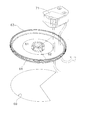
- the disassembled perspective view which shows a humidification rotor and a heater.
- the partial expanded sectional view of the outdoor unit of the air conditioning apparatus which concerns on 2nd Embodiment.
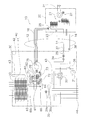
- the circuit diagram which shows the outline
- the top view of the outdoor unit which concerns on the modification of FIG. 14 in the state where the top plate was removed.
- the circuit diagram which shows the outline
- the perspective view which shows the external appearance of the state from which the grill and the outdoor heat exchanger were removed from the outdoor unit of FIG.
- the perspective view which shows the external appearance of the state which removed the front board and the top plate from the outdoor unit of FIG.
- the rear view which shows the external appearance of the state which removed the outdoor heat exchanger, the outdoor fan, the protection metal mesh, etc. from the outdoor unit of FIG.
- the rear view which shows an example of the grill concerning a 3rd embodiment.
- the outdoor unit of the air conditioning apparatus concerning this invention is not restricted to embodiment described below, It can change in the range which does not deviate from the summary of invention.
- the air conditioner 10 according to the first embodiment of the present invention has an indoor unit 20 and an outdoor unit 30 connected by a communication pipe 12. Configured.
- the air conditioner 10 has a plurality of operation modes such as a cooling operation, a heating operation, a dehumidifying operation, a humidifying operation, an air supply operation, and an exhaust operation, and these operation modes can be appropriately combined.
- the indoor unit 20 of FIG. 2 is provided with an indoor heat exchanger 21, and the outdoor unit 30 includes a compressor 31, a four-way switching valve 32, an outdoor heat exchanger 33, an electric valve 34, a filter. 35, an accumulator 36, a liquid closing valve 37 and a gas closing valve 38 are provided. Further, a liquid refrigerant pipe 14 and a gas refrigerant pipe 16 that connect the indoor unit 20 and the outdoor unit 30 pass through the communication pipe 12.
- the outdoor air is supplied to the room or the indoor air is discharged, so that the indoor unit 20 and the outdoor unit 30 are connected through the air supply duct 18 of the communication pipe 12.
- the outdoor unit 30 takes in moisture from the outside air.
- the outdoor unit 30 is provided with a humidifying unit 60 having a function of taking moisture from the outside air.
- the four-way switching valve 32 is connected in a solid line, and the refrigerant compressed and discharged by the compressor 31 is sent to the outdoor heat exchanger 33 through the four-way switching valve 32.
- the refrigerant that has been deprived of heat by exchanging heat with the outside air in the outdoor heat exchanger 33 is sent to the motor-operated valve 34.
- the high-pressure liquid refrigerant is changed to a low-pressure state by the motor-operated valve 34.
- the refrigerant expanded by the electric valve 34 enters the indoor heat exchanger 21 through the filter 35 through the liquid closing valve 37 and the liquid refrigerant pipe 14.
- the refrigerant whose temperature has risen due to heat exchange with room air in the indoor heat exchanger 21 is sent to the four-way switching valve 32 through the gas refrigerant pipe 16.
- a gas closing valve 38 and an accumulator 36 are connected in the four-way switching valve 32. Therefore, the refrigerant sent from the indoor heat exchanger 21 through the gas refrigerant pipe 16 is sent to the compressor 31 via the accumulator 36.
- the four-way switching valve 32 is connected in a dotted line, and the refrigerant compressed and discharged by the compressor 31 is sent to the indoor heat exchanger 21. Then, the refrigerant exiting the outdoor heat exchanger 33 returns to the compressor 31 along a path opposite to that during cooling. That is, the compressor 31, the four-way switching valve 32, the gas refrigerant pipe 16, the indoor heat exchanger 21, the liquid refrigerant pipe 14, the electric valve 34, the outdoor heat exchanger 33, the four-way switching valve 32, the accumulator 36, and the compressor 31. The refrigerant circulates in this order.
- an indoor fan 22 driven by a motor is provided downstream of the indoor heat exchanger 21 as shown in FIG. 2. Is provided.
- This indoor fan 22 is a cross flow fan. When the indoor fan 22 is driven, the indoor air sucked from the suction port 23 at the upper part of the indoor unit 20 shown in FIG. 1 passes through the indoor heat exchanger 21 and from the outlet 24 at the lower part of the indoor unit 20. Blown out.
- an air supply port 25 of the air supply duct 18 is provided in the upstream space of the indoor heat exchanger 21.
- the air supply duct 18 is connected to the humidification unit 60, and high-humidity air sent from the humidification unit 60 is supplied from the air supply port 25 to the upstream space of the indoor heat exchanger 21.
- the indoor fan 22 By driving the indoor fan 22 in a state where such high-humidity air is supplied from the air supply port 25, the humidity of the conditioned air blown from the air outlet 24 of the indoor unit 20 can be increased.
- the indoor heat exchanger 21 can be used as an evaporator at the same time to cause the indoor unit 20 to perform a humidifying operation and a cooling operation at the same time.
- the outdoor unit 30 includes a casing 40 and a partition plate 43, and as shown in FIG. 43 is divided into a blower chamber 41 and a machine chamber 42.
- the blower chamber 41 and the mechanical chamber 42 are shielded by the partition plate 43 so that the wind does not enter the mechanical chamber 42 from the blower chamber 41.
- an outdoor fan 39 driven by a fan motor 39 a is provided downstream of the outdoor heat exchanger 33 as shown in FIG. On the side.
- This outdoor fan 39 is a propeller fan, and has a propeller 39b driven by a fan motor 39a.
- the outdoor fan 39 is driven, the outside air sucked from the rear surface side of the outdoor heat exchanger 33 through the outdoor heat exchanger 33 is blown out from the outlet 44 of the outdoor unit 30.
- the front surface of the air outlet 44 is covered with a grille 56 so that the propeller 39 b of the outdoor fan 39 does not come into contact with an object outside the outdoor unit 30.
- the grill 56 is attached to the front plate 46 of the casing 40.
- a humidifier unit 60 is provided in the blower chamber 41 of the outdoor unit 30, and the humidifier unit 60 is disposed in front of the outdoor heat exchanger 33.
- the fact that the humidifying unit 60 is disposed in front of the outdoor heat exchanger 33 means that a part of the humidifying unit 60 is hung on the air passage passing through the outdoor heat exchanger 33.
- the humidification unit 60 in such a place is provided with a shape and an arrangement position as will be described later in order to suppress an increase in the blowing resistance of the blowing path passing through the outdoor heat exchanger 33.
- FIG. 3 is a perspective view of the outdoor unit 30 and shows a state where the grill 56 and the like are removed from the outdoor unit 30 of FIG.
- FIG. 4 is a plan view of the outdoor unit 30 and shows a state where the top plate 48 of the outdoor unit 30 is removed.
- FIG. 5 is a perspective view of the outdoor unit 30 and shows a state in which the front plate 46, the top plate 48, the left side plate 50, and the like are removed.
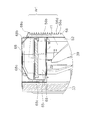
- FIG. 6 is a cross-sectional view taken along the line II of FIG.
- the casing 40 of the outdoor unit 30 includes a front plate 46, a right side plate 47, a top plate 48, and a bottom plate 49 shown in FIG. As shown in FIG.
- the outdoor heat exchanger 33 has an L shape when viewed from above, and the left side surface of the casing 40 faces the left side surface portion 332 of the L-shaped outdoor heat exchanger 33.
- a left side plate 50 is attached. Although not visible from FIG. 4, the left side plate 50 is formed in a lattice shape in order to guide outside air to the outdoor heat exchanger 33.
- the rear side of the blower chamber 41 is opened for the rear surface portion 331 of the outdoor heat exchanger 33 and is not shown, the rear side portion 331 of the outdoor heat exchanger 33 is covered on the rear side of the blower chamber 41.
- a protective wire mesh is attached.
- the partition plate 43 that partitions the casing 40 into the blower chamber 41 and the machine chamber 42 is arranged substantially in parallel with the right side plate 47.
- the partition plate 43 extends forward from the right end of the outdoor heat exchanger 33 and extends vertically from the bottom plate 49 to the top plate 48.
- the front portion of the partition plate 43 is attached in contact with the front plate 46.
- the right side plate 47 covers the rear surface from the right end of the rear surface portion 51 of the outdoor heat exchanger 33 to the right side surface and the entire right side surface.
- the opening part 43b is formed in the partition plate 43 (refer FIG. 5).
- a circular air outlet 44 shown in FIG. 3 is formed in the front plate 46, and a ring-shaped bell mouth 52 is attached around the air outlet 44.
- a part of the propeller 39b is arranged so as to enter the space surrounded by the bell mouth 52.
- the fan motor 39a is attached to the rear surface side of the propeller 39b.
- the fan motor base 53 for supporting the fan motor 39a is a vertically long metal member on the rear side of the propeller 39b.
- the fan motor base 53 includes two supporting column portions extending vertically so as not to block the flow of outside air by the propeller 39b, and these supporting column portions are connected to the upper end 33b and the bottom plate 49 of the fan motor 39a and the outdoor heat exchanger 33. It is composed of a plurality of crosspieces connected in the vicinity.
- the fan motor base 53 is attached to the bottom plate 49 and the upper end 33 b of the outdoor heat exchanger 33.
- the outdoor heat exchanger 33 has the rear surface portion 331 disposed on the rear side of the casing 40 and the left side surface portion 332 disposed on the left side surface side. It exhibits an L-shape when viewed from above.
- the outdoor heat exchanger 33 has a large number of fins extending in the height direction and heat transfer tubes that are horizontally attached through the fins and thermally connected to the large number of fins.
- the outdoor heat exchanger 33 has a height that reaches the top plate 48 from the bottom plate 49.
- the heat transfer tubes are arranged in multiple rows in the height direction by being bent back and forth at both ends of the outdoor heat exchanger 33.
- the refrigerant is arranged so that the high-temperature refrigerant enters from the heat transfer tubes in the lowermost row of the outdoor heat exchanger 33 and the refrigerant temperature decreases in the upper row, and at the low temperature from the heat transfer tubes in the uppermost row at the time of heating. It arrange
- FIG. 7 and FIG. 8 show a humidification unit 60 arranged in front of the outdoor heat exchanger 33.
- FIG. 7 is a perspective view of the humidifying unit 60 taken out and seen from the front right diagonal upper side of the humidifying unit 60
- FIG. 8 is a perspective view of the humidifying unit 60 seen from the rear right diagonal upper side.
- FIGS. 7 and 8 show a state in which the upper cover 67 shown in FIGS. 4 and 5 is removed.
- the feature of the outdoor heat exchanger 33 is that the humidifying unit 60 is exposed in front of the outdoor heat exchanger 33.
- the height of the position of the upper surface 60 a of the humidifying unit 60 matches the height of the upper end 33 b (top) of the outdoor heat exchanger 33.
- the humidifying unit 60 is given a shape with a volume as small as possible while maintaining a relatively complicated appearance.
- the grill 56 shown in FIG. 1 is attached to the front plate 46 of the casing 40 and covers the air outlet 44.
- a large number of openings 56a shown in FIG. 9 are formed in the grill 56 to blow out the outside air.
- a guide structure 56b is formed on the upper left portion of the grill 56 with a resin plate. That is, in order to form such a plate-shaped guide structure 56b, the region Ar1 has a structure in which the space between the crosspiece 56d and the crosspiece 56d of the grill 56 is closed.
- the guide structure 56b is formed by performing processing while avoiding the formation of the opening 56a in the portion that becomes the guide structure 56b.
- the grill 56 is formed by injection molding, for example, a mold is created so that an area corresponding to the guide structure 56b is closed.
- a step for separately forming the guide structure 56b can be omitted.
- the guide structure 56b is formed outside the casing 40 in order to make the casing 40 compact.
- the guide structure 56b is formed so as to be applied to a part of the air outlet 44 in a front view, and blocks a part of the outside air blown forward from the air outlet 44. Yes.
- the blocked outside air is guided upward along the guide structure 56b as shown by a path r1 indicated by a two-dot chain line in FIG.
- the outside air guided upward along the guide structure 56b enters the intake port 68a that is only open because the upper portion of the grill 56 is blocked. That is, as shown in FIG.
- an overlapping portion 56 b 1 between the upper end and both left and right ends of the guide structure 56 b and the front plate 46 serves as a passage, and the guide structure 56 b and the air outlet 44.
- the outside air guided from the overlapping portion 56b2 to the upper overlapping portion 56b1 enters the intake port 68a.
- the area of the overlapping portion 56b2 where the guide structure 56b is applied to the air outlet 44 increases as viewed from the front, the amount of the outside air guided to the intake port 68a increases, but the amount of the outside air guided to the outdoor heat exchanger 33 is increased. Cause a decline. Therefore, the area where the guide structure 56b is applied to the air outlet 44 is set so that an appropriate air volume is distributed to both.
- the humidification unit 60 includes a moisture absorption unit 61 for absorbing moisture from the outside air and a moisture release unit for releasing moisture to humidify the air. 62.
- (3-5-1) Moisture Absorption Unit and Moisture Release Unit In the humidification unit 60, the moisture absorption unit 61 and the moisture release unit 62 are separated by a single disc-shaped humidification rotor 63 as shown in FIG. It is configured. That is, the humidification rotor 63 is a moisture absorbing / releasing material that serves as both the moisture absorbing portion 61 and the moisture releasing portion 62.
- the disc-shaped humidification rotor 63 is a zeolite rotor having a honeycomb structure formed by firing zeolite or the like.
- the humidifying rotor 63 is mounted so as to rotate about the center of the disk as a rotation axis, and is rotationally driven by the power of a rotor driving motor (not shown) transmitted to a gear 64 provided around the humidifying rotor 63.
- the adsorbent such as zeolite forming the humidifying rotor 63 has a property of absorbing moisture from air at room temperature, for example, and releasing moisture when air heated to a high temperature by the heater 71 is heated to a temperature higher than room temperature. Yes.
- the side of the humidifying rotor 63 that is exposed to high-temperature air becomes the moisture absorbing portion 61, and the side that is exposed to high-temperature air becomes the moisture releasing portion 62.
- the humidification rotor 63 absorbs moisture on the side where the temperature of the humidification rotor 63 is low, and releases moisture on the side where the temperature of the humidification rotor 63 is high.
- the moisture adsorbed by the humidification rotor 63 by the moisture absorption by the moisture absorption unit 61 is carried to the moisture release unit 62 as the humidification rotor 63 rotates, and the moisture release by the moisture release unit 62 is performed.
- the moisture adsorbed by the air is desorbed and the air around the moisture release unit 62 is humidified.
- a heater 71 is provided above the moisture release unit 62 in order to heat the air passing through the moisture release unit 62 of the humidification rotor 63.
- the moisture absorption duct 68 has an intake port 68a that is open toward the front side and sucks outside air from the front side.
- the hygroscopic duct 68 has an inclined portion 68b following the intake port 68a formed at the upper part of the hygroscopic duct 68. Therefore, when viewed from the side, the hygroscopic duct 68 is downward. It becomes a curved shape. Since the moisture absorption duct 68 has such a downwardly curved structure, the outside air blown upward from the lower side can easily enter from the intake port 68 a of the moisture absorption duct 68.
- the moisture absorption duct 68 spreads up and down as it advances from the intake port 68a to the rear surface side, and the outside air that advances from the intake port 68a to the rear surface side spreads up and down as it advances toward the rear surface side, and reaches the entire moisture absorption part 61. It becomes easy. As shown in FIG. 4, the moisture absorption duct 68 covers the entire surface of the moisture absorption part 61, and the outside air passes through the humidification rotor 63 disposed below from the top to the bottom.
- the exhaust port 69 is below the humidification rotor 63.
- the exhaust port 69 occupies an area substantially equal to the projected portion from the upper surface of the hygroscopic duct 68.
- a propeller 39b is arranged below the exhaust port 69 as shown in FIGS. That is, the exhaust port 69 faces the space 70 that becomes negative pressure when the propeller 39b rotates. With such a configuration, the outside air blown out from the bell mouth 52 by the propeller 39b and entered the intake port 68a is drawn toward the negative pressure space 70 through a path indicated by a two-dot chain line in FIG. Then, the air is blown out from the exhaust port 69 to the blower chamber 41. Therefore, only the outdoor fan 39 sends outside air to the moisture absorption unit 61, and a dedicated fan for sending outside air to the moisture absorption unit 61, which has been conventionally required, can be omitted.
- FIG. 10 a heater 71 is provided above the moisture release portion 62 of the humidification rotor 63 in order to release moisture from the moisture release portion 62.
- FIG. 11 is a bottom view of the heater 71 and the heater support member 74 as viewed from below.
- the heater 71 has a structure in which a heating wire (not shown) is provided in a cylindrical casing, and heats the outside air sucked from the suction port 72 and sent to the humidification rotor 63 with a heating wire.
- a heating wire not shown
- the air in the humidification duct 73 is humidified by dehumidification from the humidification rotor 63.
- the heater 71 is attached to the lower side of the heater support member 74.
- the heater support member 74 has a top surface portion 74a, a peripheral outer wall portion 74b, and a fixing plate 74c.
- the heater support member 74 is a cylindrical body whose upper surface and side surfaces are surrounded by the upper surface portion 74a and the outer wall portion 74b, and the lower portion is released. .
- the casing of the heater 71 and the heater support member 74 are made of sheet metal because heat resistance is required.
- the suction port 72 is located on the front side of the heater support member 74 and below the humidification rotor 63, and the outside air sucked from the suction port 72 and passed through the humidification rotor 63 passes through the housing of the heater 71 from the front side. Passes toward the rear side. At this time, the outside air is heated by the heater 71. The air that has passed through the casing of the heater 71 passes over the humidification rotor 63 and advances to the rear side. Since the lower part on the rear surface side of the humidification rotor 63 is connected to the humidification duct 73 (see FIG.
- the air that has reached the upper side of the humidification duct 73 passes through the humidification rotor 63 downward and is then supplied to the humidification duct. Inhaled by 73.
- the humidification rotor 63 is exposed to the air whose temperature has been increased by the heater 71 and dehumidifies. In this way, the air humidified by the humidification rotor 63 is guided to the indoor unit 20 through the humidification duct 73. Therefore, as shown in FIG. 10, in the humidification rotor 63, the lower part of the heater support member 74 becomes the moisture release part 62, and the other part becomes the moisture absorption part 61.
- the humidification rotor 63 rotates clockwise as viewed from above, and functions as the moisture release portion 62 when the portion of the humidification rotor 63 that functions as the moisture absorption portion 61 rotates and comes under the heater support member 74. That is, the humidification rotor 63 is a moisture absorbing / releasing material that serves as both the moisture absorbing portion 61 and the moisture releasing portion 62.
- the humidification duct 73 is located on the lower rear surface side of the humidification rotor 63 and in front of the outdoor heat exchanger 33 as described above. It becomes a blowing resistance for the outside air passing through the exchanger 33. Further, if the turbo fan 75 is also disposed in front of the outdoor heat exchanger 33, it causes air blowing resistance. Therefore, the turbo fan 75 having a relatively large occupied volume is as shown in FIGS. Installed in the machine room 42.
- the propeller 39b is disposed below the humidifying unit 60, and even at the highest position in the rotating region of the propeller 39b, the amount of the humidifying unit 60 is higher than the upper end 33b of the outdoor heat exchanger 33. It will be located below.
- the humidifying duct 73 is turbocharged so that the humidifying duct 73 is located at the same position as the upper end 33b of the outdoor heat exchanger 33 so that the humidifying duct 73 does not obstruct the flow path of the outside air as much as possible. It is arranged obliquely toward the fan 75. As shown in FIG. 2, a damper 78 is attached to the humidifying duct 73 to prevent a reverse flow in the humidifying duct 73 during the humidifying operation, that is, a flow of air flowing from the turbo fan 75 side to the humidifying rotor 63. is doing.
- the turbo fan 75 is arranged so that it does not take up space in the front-rear direction.
- the rotary shaft of the impeller of the turbo fan 75 is arranged vertically so that it extends in the front-rear direction.
- the suction port 76 of the turbo fan 75 is arranged with the humidifying unit 60 facing toward it.
- the discharge port 77 of the turbo fan 75 is disposed obliquely downward.
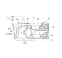
- FIG. 12 is a partial cross-sectional view of the outdoor unit 30 for showing the cross-sectional shape of the humidification unit 60.
- the humidifying unit 60 is fixed on the fan motor base 53 with screws 53a. Further, the front of the humidifying unit 60 reaches the front plate 46. In the fixed state, the humidification unit 60 does not move back and forth and left and right. Therefore, a predetermined gap Is is formed between the front surface 33a of the outdoor heat exchanger 33 and the rear surface 60b of the humidifying unit 60. This gap Is is reliably maintained by the rib 60c formed on the rear surface 60b.
- an inclined portion 68c is formed on the rear surface side of the moisture absorption duct 68, and the surrounding wall 65 shown in FIG. 12 is provided with an inclined portion 65c that is inclined so as to protrude forward as it goes downward. ing.
- the inclined portion 65c is provided and the lower portion is inclined as shown in FIG. 12, the passage of outside air is improved.
- the outside air flows like the path r2 shown in FIG. 12, and the outside air passes through the outdoor heat exchanger 33 on the rear surface side of the humidifying unit 60 and passes therethrough. Since the outside air to be heat-exchanged, it can suppress that heat exchange efficiency falls. Further, since the upper inclined portion 68c of the humidifying unit 60 is present, the outside air that passes through the outdoor heat exchanger 33 toward the front and hits the inclined portion 68c hits the humidifying unit 60 and advances forward on the left side. As shown in FIG. 4, the outside air that has advanced to the left side flows downward from the space 41a between the outdoor heat exchanger 33 and the humidifying unit 60, and a path r3 toward the propeller 39b is formed.
- Second Embodiment In the first embodiment, only the air flow generated by the outdoor fan 39 that is guided to the intake port 68a by the guide structure 56Ab is sucked into the intake port 68a of the moisture absorption duct 68. Since the structure of 1st Embodiment can fully utilize the airflow of the outdoor fan 39, it is a structure which is easy to ensure the quantity of the external air suck
- the outdoor unit 30A of the second embodiment shown in FIG. 13 has an opening 56Aba in the guide structure 56Ab of the grill 56A.
- the opening 56Aba is provided to face the intake port 68a. Therefore, a path r1 that proceeds along the guide structure 56Ab and enters the intake port 68a and a path r4 that directly enters the intake port 68a from the opening 56Aba are formed. At this time, the outside air is guided to the intake port 68a through the route r4 along with the outside air sent through the route r1.
- the negative pressure space 70 from the outdoor heat exchanger 33 to the portion partitioned by the outdoor fan 39 and the bell mouth 52 becomes negative pressure when the outdoor fan 39 is rotating. It is space.
- the exhaust port 69 faces the negative pressure space 70, and an airflow is generated from the side where the humidification rotor 63 exists toward the negative pressure space 70 with the exhaust port 69 interposed therebetween.
- an air flow blown out from the air outlet 44 is generated.
- a path through which the air whose direction has been changed by the guide structures 56 b and 56 Ab shown in FIGS. 9 and 13 passes from the air outlet 44 to the air outlet 68 a and then to the air outlet 69 through the moisture absorbing portion 61.
- the outdoor fan 39 can efficiently guide the outside air to the moisture absorption unit 61, and the moisture absorption function is improved. As a result, it is possible to omit a dedicated fan and a drive motor for the dedicated fan that have been conventionally provided to guide the outside air to the moisture absorption unit 61.
- a dedicated fan etc. were omitted was demonstrated in the said embodiment, if a dedicated fan and a drive motor can be reduced in size even if it does not omit, the humidification unit 60 can be downsized. If the humidification unit 60 can be reduced in size, downsizing of the outdoor unit 30 can be achieved.
- the configuration of the first embodiment shown in FIG. 9 is a configuration in which only the air guided along the guide structures 56b and 56Ab via the outdoor fan 39 is sucked by the intake port 68a. With such a configuration, the outside air can be efficiently guided to the intake port 68a by fully utilizing the air flow generated by the outdoor fan 39.
- the air guided along the guide structure 56Ab along the route r1 (first route) can be used to draw in the air guided along the route r4 (second route). By using r4, it becomes easy to introduce air having a higher humidity than the air of the route r1 (first route) into the moisture absorption part.
- the guide structures 56b and 56Ab are formed on the grilles 56 and 56A, and the guide structures 56b and 56Ab are attached to the front plate 46 together with the grilles 56 and 56A. Yes. That is, the guide structures 56b and 56Ab can be attached by attaching the grilles 56 and 56A, and the guide structures 56b and 56Ab can be attached very easily.
- the grills 56 and 56A and the guide structures 56b and 56Ab are integrally formed. However, the grilles 56 and 56A and the guide structures 56b and 56Ab may be separated. In addition to the case where the guide structures 56b and 56Ab are indirectly attached to the front plate 46 via the grills 56 and 56A as in the above embodiment, the guide structures 56b and 56Ab are directly attached to the front plate 46. There may be. (4-5) As described above, the guide structures 56b and 56Ab are formed on the grills 56 and 56A, and are configured by portions where the openings 56a of the grilles 56 and 56A are not punched. Therefore, the guide structures 56b and 56Ab can be formed simultaneously with the formation of the grills 56 and 56A. Therefore, it is not necessary to add a dedicated process for forming the guide structures 56b and 56Ab, and the outdoor units 30 and 30A having the guide structures 56b and 56Ab can be provided at low cost.
- the humidifying unit 60 has a moisture absorption duct 68 disposed above the outdoor fan 39.
- the hygroscopic duct 68 that guides outside air from the air inlet 68a to the hygroscopic portion 61 is curved downward when a line passing between the upper end and the lower end of the duct is connected. Since it is curved downward, it becomes easy for the moisture-absorbing duct 68 to suck the outside air rising from below through the path r1, and the outside air supplied to the moisture-absorbing portion 61 is increased to improve the humidifying performance. .
- the type of the air conditioner to which the present invention can be applied is a pair type. Not limited.
- the present invention can be applied to a multi-type air conditioner in which a plurality of indoor units are connected to a single outdoor unit.
- the outdoor unit of the present invention can be configured.
- a partitioned space other than the blower chamber 41 and the machine chamber 42 may be formed.
- the machine chamber 42 may be provided as another chamber including other functions.
- the outdoor heat exchanger 33 has been described as having an L-shape when viewed from above, but the outdoor heat exchanger that constitutes the outdoor unit of the present invention is not limited to the shape described above. For example, an outdoor heat exchanger having an I-shape when viewed from the top can be used.
- an exhaust duct 80 may be provided. Even when such an exhaust duct is provided, it is preferable to provide a gap Is2 (see FIG. 6) that is equal to or larger than the predetermined gap Is between the front surface 33a of the outdoor heat exchanger 33 and the rear surface of the exhaust duct. Further, it is preferable that an inclined portion is provided below the exhaust duct 80 and the air blowing resistance is reduced by the inclined portion 80a.
- the outdoor fan 39 has the propeller 39b. However, the outdoor fan 39 is not limited to the propeller 39b.
- the outdoor unit of the present invention can also be configured by an outdoor fan having blades other than the propeller type.
- the moisture absorption part 61 is larger than the moisture release part 62 and the center angle ⁇ of the moisture absorption part 61 is in a sector shape larger than 180 degrees as shown in FIG.
- the size of 61 and the moisture release part 62 can be set as appropriate.
- the center angles can be set to 180 degrees so that the moisture absorbing portion 61 and the moisture releasing portion 62 are substantially equal in size.
- a dedicated fan for guiding the outside air to the moisture absorption unit 61 and a motor for driving the fan are omitted.
- a dedicated fan or a dedicated fan motor that is smaller than the conventional fan is attached. Also good.
- the dedicated fan only for guiding the outside air to the moisture absorption unit 61 and the motor for the dedicated fan can be reduced as compared with the conventional one.
- the outdoor unit can be made more compact than before.
- the partition plate 43 illustrated in FIGS. 14 and 15. It can also comprise so that it may partition between.
- the partition plate 43 is disposed at the boundary between the moisture absorbing portion 61 and the moisture releasing portion 62, so that the moisture releasing portion 62, the humidifying duct 73, and the turbo fan 75 are connected to the machine. It can be configured to be installed in the chamber 42. Thereby, it is possible to prevent the moisture release unit 62 from being cooled by the outside air that has passed through the outdoor heat exchanger 33.
- the ventilation resistance is thereby increased. Can be reduced. Also in such a modification, the above-described guide structure can be applied by moving the position of the guide structure toward the partition plate 43 in accordance with the position of the intake port 68a.
- the direction in which the rotation axis extends can be configured to coincide with the left-right direction that is the longitudinal direction of the casing 40.
- the direction in which the rotating shaft extends coincide with the longitudinal direction of the casing 40, the length of the casing in the longitudinal direction can be easily shortened.
- the outline of the configuration of the air conditioner incorporating the outdoor unit 30B according to the third embodiment shown in FIGS. 17 to 23 is shown in FIG. Although it is substantially the same as the outline
- the outdoor unit 30B of the third embodiment also includes a casing 40B and a partition plate 43B. As shown in FIGS. The internal space is divided into a blower chamber 41B and a machine chamber 42B by a partition plate 43B.
- the outdoor unit 30B in order to constitute a refrigerant circuit, like the outdoor unit 30, the compressor 31, the four-way switching valve 32, the outdoor heat exchanger 33, the electric valve 34, the filter 35, the accumulator 36, the liquid closing valve 37 and A gas closing valve 38 is provided. Further, as shown in FIG. 20, an outdoor fan 39 ⁇ / b> B in which the propeller 39 ⁇ / b> Bb is driven by the fan motor 39 ⁇ / b> Ba is provided on the downstream side of the outdoor heat exchanger 33. The propeller 39Bb rotates counterclockwise when viewed from the front. And the humidification unit 60B is installed in the space of the blower chamber 41B, and is disposed above the outdoor fan 39B.
- the point which the humidification unit 60B has the moisture absorption part 61 and the moisture release part 62 is the same as the humidification unit 60 of 1st Embodiment.
- the humidifying unit 60B has a single disc-shaped humidifying rotor 63 and a heater 71 as shown in FIG. 10, the moisture absorbing duct 68 shown in FIG. 9, and FIG. 7 and an intake port 72B (see FIG. 20) corresponding to the intake port 72 shown in FIG. 7, and a turbo corresponding to the humidifying duct 73 and the turbo fan 75 shown in FIG.
- the point which has the fan 75B is the same as that of the humidification unit 60 of 1st Embodiment.
- the suction port 72B of the humidification unit 60B is different from the suction port 72 of the humidification unit 60 in the shape and size, and the structure in which the outside air sucked from the suction port 72B is sent to the humidification rotor 63 is also the humidification unit 60B.
- the turbo fan 75 of the humidifying unit 60 is placed vertically, whereas the turbo fan 75B of the humidifying unit 60B is placed horizontally. That is, the rotating shaft of the impeller of the turbo fan 75 extends in the front-rear direction, whereas the rotating shaft of the impeller of the turbo fan 75B extends in the up-down direction.
- the turbo fan 75B is disposed in the blower chamber 41B above the propeller 39Bb. However, the turbo fan 75B is placed in the blower chamber 41B so that an increase in ventilation resistance can be suppressed by being placed horizontally. It is attached.
- FIG. 20 shows a humidification unit 60 ⁇ / b> B arranged in front of the outdoor heat exchanger 33.
- the humidifying unit 60B is exposed in front of the outdoor heat exchanger 33.
- the height of the position of the upper surface 60Ba of the humidifying unit 60B matches the height of the upper end 33b (top) of the outdoor heat exchanger 33.
- the humidifying unit 60B is given a shape with a volume as small as possible while maintaining a relatively complicated appearance.
- the height of the position of the upper surface 60Ba of the humidifying unit 60B is made to coincide with the height of the upper end 33b of the outdoor heat exchanger 33, but it is not always necessary to make it coincide, and the humidifying unit is placed in front of the outdoor heat exchanger 33.
- the outdoor unit 30B is made compact by arranging 60B to be exposed.
- FIG. 18 is a front view of the outdoor unit 30B
- FIG. 19 is a perspective view of the outdoor unit 30B
- FIG. 19 shows a state where the grill 56 and the like are removed from the outdoor unit 30B of FIG. Has been.
- the casing 40B of the outdoor unit 30B includes a front plate 46B, a right side plate 47, a top plate 48, and a bottom plate 49.
- a left side plate formed in a lattice shape is attached to the left side surface of the casing 40 ⁇ / b> B so as to face the left side surface portion of the L-shaped outdoor heat exchanger 33.
- a protective wire mesh that covers the rear surface of the outdoor heat exchanger 33 is attached to the rear side of the blower chamber 41B of the casing 40B, and the rear side of the blower chamber 41B is open.
- a circular air outlet 44 shown in FIG. 19 is formed in the front plate 46B, and a ring-shaped bell mouth 52 is attached around the air outlet 44B.
- a part of the propeller 39Bb is arranged so as to enter the space surrounded by the bell mouth 52.
- the important points are the opening 46Ba for the intake port 68a and the opening 46Bb for the intake port 72B. Is a point formed separately on the front plate 46B.
- the front plate 46 of the casing 40 of the first embodiment has only one opening 46a (see FIG. 3) for the intake port 68a and the intake port 72.
- the two openings 46Ba and 46Bb of the front plate 46B are separated by a rib 56q (see FIG. 23) of a grill 56B described later. (5) Grille FIG.
- FIG. 21 shows a state where the grille 56B attached to the casing 40B is viewed from the back side with the outdoor heat exchanger 33, the outdoor fan 39B, etc. removed from the casing 40B.
- FIG. 22 is a rear view of the grill 56B
- FIG. 23 is a perspective view of the grill 56B as viewed from diagonally above the rear.
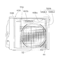
- the grill 56B shown in FIG. 18 is attached to the front plate 46B of the casing 40B and covers the air outlet 44.
- a large number of openings 56a are formed between the crosspiece 56d and the crosspiece 56d in the grill 56B.
- a guide structure 56Bb is formed of a resin plate on the top of the grill 56B.
- the guide structure 56Bb is formed so as to hang over a part of the air outlet 44 in front view (or rear view), and is blown out forward from the air outlet 44. Blocks part of the air flow.
- resin molding is performed by performing injection molding so that the space between the crosspiece 56d and the crosspiece 56d is not formed and the opening 56a is not formed in the portion that becomes the guide structure 56Bb in the same manner as the formation of the grille 56.
- a guide structure 56Bb can be formed on the grill 56B. As shown in FIG.
- the guide structure 56Bb has an overlapping portion 56Bb1 with the front plate 46B and an overlapping portion 56Bb2 with the outlet 44.
- the space between the overlapping portion 56Bb1 with the front plate 46B and the front plate 46B becomes a passage, and the outside air whose direction is changed at the overlapping portion 56Bb2 with the outlet 44 is overlapped with the front plate 46B and the front plate 46B. It is guided to the intake port 68a through the formed passage.
- the area of the overlapping portion 56Bb2 with the air outlet 44 increases, the air volume of the outside air guided to the air inlet 68a increases, while the airflow resistance increases at the overlapping portion 56Bb2 with the air outlet 44 and is led to the outdoor heat exchanger 33.
- the air volume of the outside air is reduced. Therefore, the area of the overlapping portion 56Bb2 with the outlet 44 is set so that an appropriate air volume is distributed to both.
- a suction opening 56p is formed at a position facing the suction port 72B.
- the periphery of the suction opening 56p is surrounded by a rib 56q, and the outside air sucked from the suction port 72B is not blown by the outdoor fan 39B but is taken from the front of the outdoor unit 30B.
- the guide structure 56Bb blocks outside air from the air outlet 44 toward the air inlet 68a so as not to be sucked into the air inlet 72B by the rib 56q surrounding the air inlet 56p.
- a rib 56r is formed below the suction opening 56p.
- the ribs 56r are formed in a plate shape with a smooth surface, and extend in the rotation direction of the outdoor fan 39B.
- the rib 56r extends in a direction substantially orthogonal to a straight line extending radially from the rotation center 39Bb1 of the propeller 39Bb of the outdoor fan 39B.
- the intake port 68a faces the area Ar2 surrounded by the two-dot chain line in FIG.
- the rib 56r, the front plate 56B, and the guide structure 56Bb form a channel surrounded by three sides of the path r5 shown in FIG. With this channel, it is possible to smoothly guide outside air swirled from the outlet 44 in the rotation direction of the propeller 39Bb of the outdoor fan 39B along the path r5.
- the outdoor fan 39B can efficiently guide the outside air to the moisture absorption unit 61, and the moisture absorption function is improved. As a result, it is possible to omit a dedicated fan and a drive motor for the dedicated fan that have been conventionally provided to guide the outside air to the moisture absorption unit 61.
- a dedicated fan etc. were omitted was demonstrated in the said embodiment, if a dedicated fan and a drive motor can be reduced in size even if it does not omit, the humidification unit 60B can be downsized. If the humidification unit 60B can be reduced in size, downsizing of the outdoor unit 30B can be achieved.
- the configuration of the third embodiment shown in FIG. 23 is a configuration in which only the air guided by the route r5 along the guide structure 56Bb via the outdoor fan 39B is sucked by the intake port 68a. With such a configuration, the outside air can be efficiently guided to the intake port 68a by fully utilizing the air flow generated by the outdoor fan 39.
- the configuration in which the air guided by the route r1 (first route) along the guide structure 56Ab shown in FIG. 13 is used to draw in the air guided by the route r4 (second route).
- an opening is provided in the guide structure 56Bb facing the intake port 68a of the third embodiment as in the opening 56Aba of the second embodiment to create a route corresponding to the route r4.
- high-humidity air may be introduced into the hygroscopic portion 61.
- the guide structure 56Bb is formed on the grill 56B, and the guide structure 56Bb is attached to the front plate 46B together with the grill 56B. That is, the guide structure 56Bb can be attached by attaching the grill 56B, and the guide structure 56Bb can be attached very easily.
- the grill 56B and the guide structure 56Bb are integrally formed. However, the grill 56B and the guide structure 56Bb may be separated.
- the guide structure 56Bb may be directly attached to the front plate 46B.
- the guide structure 56Bb is formed on the grill 56B, and is configured by a portion where the opening 56a of the grill 56B is not formed. Therefore, the guide structure 56Bb can be molded simultaneously with the grill 56B. As a result, it is not necessary to add a dedicated process for forming the guide structure 56Bb, and the outdoor unit 30B having the guide structure 56Bb can be provided at low cost.
- the humidifying unit 60 ⁇ / b> B has a moisture absorbing duct 68 disposed above the outdoor fan 39 ⁇ / b> B, similarly to the humidifying unit 60.
- the moisture absorbing duct 68 of the humidifying unit 60B is curved downward when connecting a line passing through the middle between the upper end and the lower end. Therefore, the moisture absorption duct 68 can easily take in the outside air rising from below through the path r1, and the outside air supplied to the moisture absorption unit 61 is increased, so that the humidification performance is improved.
- the ribs 56r shown in FIGS. 22 and 23 are partition members that are disposed between the guide structure 56Bb and the front plate 46B and partition the space between the guide structure 56Bb and the front plate 46B.
- the air flow guided from the air outlet 44 to the air inlet 68a passes through a channel that surrounds the three sides of the front plate 46B, the guide structure 56Bb, and the ribs 56r. Since the air flow is surrounded by the channel formed by providing the ribs 56r (partition members), the air flow that does not reach the intake port 68a by being deviated from this passage is suppressed, so that the air efficiently flows into the intake port 68a. Can be sent in.
- the partition member is preferably in contact with the front plate 46B to partition the space without a gap, for example, but it is not necessarily required to be in contact with the front plate 46B. There is no.
- an exhaust duct 80 similar to the humidifying unit 60 shown in FIG. 5 may be provided.
- the outdoor fan 39B has the propeller 39Bb.
- the outdoor fan 39B is not limited to the propeller 39Bb.
- the outdoor unit of the present invention can also be configured by an outdoor fan having blades other than the propeller type.
- a dedicated fan for guiding the outside air to the moisture absorption unit 61 and a motor for driving the fan are omitted.
- a dedicated fan and a dedicated fan motor which are smaller than the conventional ones are omitted. It may be attached.
- the outdoor unit can be made more compact than before.
- the case where the turbo fan 75B and the air supply duct 18 are partitioned by the partition plate 43B has been described. However, as described in the first embodiment or the second embodiment, other places are partitioned. May be. (7-8)
- the rib 56s is formed only at a portion excluding the overlapping portion 56Bb2 with the air outlet 44 of the guide structure 56Bb.
- the guide structure may have a baffle member that hinders the flow of air from the intake port toward the blowout port in the vicinity of the end near the rotation center of the outdoor fan.
- the rib 56t may be formed as a baffle member at the end portion 56Cb3 of the guide structure 56Cb close to. In this case, the flow of air from the intake port 68a toward the outlet 44 can be suppressed by the rib 56t, so that the amount of air guided to the intake port 68a increases compared to the grill 56B.
- the grill 56C has the same structure as the grill 56B except for the structure of the rib 56s.
- the baffle member is not limited to the rib structure such as the rib 56t, but may be formed of other members such as a plastic film or a sponge. However, the baffle member has a structure that can be integrally formed with the grill 56B like the rib 56t. preferable.
- the grill 56C of the third embodiment has a flat inner surface of the guide structure 56Cb.
- a rectifying member that is disposed between the guide structure and the front plate and extends smoothly from the air outlet toward the air inlet may be provided.
- the grille 56D shown in FIGS. 25 and 26 is used instead of the grille 56B shown in FIG. 22, and the inner surface of the guide structure 56Db, that is, the guide structure 56Db and the front plate 56B is disposed and blown.
- a rib 56u that extends smoothly from the outlet 44 toward the intake port 68a may be provided as a rectifying member.
- the grill 56D has the same structure as the grill 56B except for the structures of the ribs 56s and the ribs 56u.
- the rectifying member is not limited to the rib structure such as the rib 56u, but a structure that can be integrally formed with the grill 56B like the rib 56u is preferable.
Landscapes
- Engineering & Computer Science (AREA)
- Chemical & Material Sciences (AREA)
- Combustion & Propulsion (AREA)
- Mechanical Engineering (AREA)
- General Engineering & Computer Science (AREA)
- Air Humidification (AREA)
- Other Air-Conditioning Systems (AREA)
- Central Air Conditioning (AREA)
Abstract
Description
このような加湿機能を有する室外機のダウンサイジングを図るため、特許文献1や特許文献2に記載の空気調和装置では、加湿ユニットの加湿ロータ(吸着回転体やデシカントローター)が水平に設置されている。
本発明の課題は、加湿機能を有する室外機において、加湿性能の低下を防止しつつ室外機のダウンサイジングを図ることにある。
第2観点の室外機によれば、室外ファンを経由してガイド構造に沿って導かれた空気のみを吸気口で吸気するので、室外ファンによって発生する気流を十分に利用して外気を効率よく吸気口に導くことができる。
第3観点の室外機によれば、ガイド構造に沿って流れる空気を第2経路で導かれる空気を呼び込むために用いることができ、第2経路を使うことで第1経路の空気よりも湿度の高い空気を吸湿部に導入し易くなる。
第4観点の室外機によれば、ガイド構造が前板に取り付けられているので、ガイド構造の取り付けが簡単になる。
第5観点の室外機によれば、ガイド構造がグリルに形成されているので、グリルの形成時にガイド構造を形成することができる。
第6観点の室外機によれば、仕切部材を設けることによって形成されるチャネルにより空気の流れが囲まれることから、この通路から外れて吸気口に到達しない空気の流れが削減されるので、吸気口に空気を効率良く送り込むことができる。
第7観点の室外機によれば、仕切部材が室外ファンの回転方向に延びていることから、室外ファンから吹出して室外ファンの回転方向に旋回する空気の流れにおいて仕切部材により生じる圧力を小さくすることができる。
第8観点の室外機によれば、バッフル部材で吸気口から吹出口の方向に向かう空気の流れを抑制することができるので、バッフル部材がない場合に比べて吸気口に導く空気の量を増やすことができる。
第9観点の室外機によれば、整流部材に沿って吸気口に向かって空気が流れるため空気の流れが整えられるので、吸気口に向かう空気の流れに起因して生じる音を低く抑えることができる。
第10観点の室外機によれば、室外機の下方から上方に向かう室外ファンの送風によって吸湿用ダクトを経由して吸湿部へ外気を導きやすくなる。
本発明の第2観点に係る空気調和装置の室外機では、ガイド構造によって外気を効率よく吸気口に導くことができ、外気を吸湿部に導くための他の構造を小型化し易くなる。
本発明の第3観点に係る空気調和装置の室外機では、第2経路を使って第1経路の空気よりも湿度の高い空気を吸湿部に導入すると、加湿性能を向上させることができる。
本発明の第4観点に係る空気調和装置の室外機では、ガイド構造の取り付けが簡単であり、ダウンサイジングされた室外機を安価に提供することができる。
本発明の第5観点に係る空気調和装置の室外機では、ガイド構造を有する室外機を安価に提供できる。
本発明の第7観点に係る空気調和装置の室外機では、吸気口へ導く空気の流れにおいて仕切部材により生じる圧力を小さくすることで、加湿性能を向上させることができる。
本発明の第8観点に係る空気調和装置の室外機では、バッフル部材により十分な空気を吸湿部に供給し易くなり、加湿性能を向上させることができる。
本発明の第9観点に係る空気調和装置の室外機では、整流部材により騒音を抑えることができる。
本発明の第10観点に係る空気調和装置の室外機では、吸湿部へ供給される外気が増えることによって加湿性能が向上する。
<第1実施形態>
(1)空気調和装置の構成の概要
本発明の第1実施形態に係る空気調和装置10は、図1に示されているように、室内機20と室外機30とが連絡配管12によって接続されて構成されている。この空気調和装置10は、冷房運転、暖房運転、除湿運転、加湿運転、給気運転及び排気運転などの複数の運転モードを持っており、これらの運転モードを適宜組み合わせることもできる。
冷房運転や暖房運転においては、室内の空気を冷やしたり温めたりするため、室内機20及び室外機30でそれぞれ熱交換が行われ、連絡配管12を通して室内機20と室外機30との間で熱の移動がある。このような熱交換と熱の移動とを行わせるために、例えば空気調和装置10には図2に示されている冷媒回路が形成される。冷媒回路を形成するため、図2の室内機20には室内熱交換器21が設けられ、室外機30には圧縮機31、四路切換弁32、室外熱交換器33、電動弁34、フィルタ35、アキュムレータ36、液閉鎖弁37及びガス閉鎖弁38が設けられている。また、室内機20と室外機30とを結ぶ液冷媒配管14及びガス冷媒配管16が連絡配管12の中に通っている。
(1-1)冷媒回路の動作
冷媒回路の動作は従来からあるものと変わらないが、図2に示されている冷媒回路の動作について簡単に説明する。
冷房時には、四路切換弁32が実線の接続になっており、圧縮機31で圧縮されて吐出された冷媒が四路切換弁32を介して室外熱交換器33に送られる。室外熱交換器33で外気との熱交換が行われて熱を奪われた冷媒は、電動弁34に送られる。高圧液状の冷媒が電動弁34で低圧状態に変化する。電動弁34で膨張した冷媒は、フィルタ35を介して液閉鎖弁37及び液冷媒配管14を通って室内熱交換器21に入る。室内熱交換器21で室内空気との熱交換が行われて熱を奪って温度が上昇した冷媒は、ガス冷媒配管16を通って四路切換弁32に送られる。四路切換弁32では、ガス閉鎖弁38とアキュムレータ36とが接続されている。そのため、ガス冷媒配管16を通って室内熱交換器21から送られてきた冷媒は、アキュムレータ36を介して圧縮機31に送られる。
(2)室内機の構成
室内機20には、室内熱交換器21の他に、図2に示されているように、モータで駆動される室内ファン22が室内熱交換器21の下流側に設けられている。この室内ファン22はクロスフローファンである。室内ファン22が駆動されると、図1に示されている室内機20上部の吸込口23から吸い込まれた室内空気が、室内熱交換器21を通過して室内機20下部の吹出口24から吹き出される。
(3)室外機の構成
(3-1)室外機の構成の概要
室外機30は、ケーシング40と仕切板43とを備えており、図2に示すように、ケーシング40の内部空間が仕切板43によって送風機室41と機械室42とに分けられている。言い換えれば、室外機30では、送風機室41から機械室42に風が回り込まないように、送風機室41と機械室42とが仕切板43によって遮蔽されているということである。
この室外機30の送風機室41には加湿ユニット60が設けられており、加湿ユニット60が室外熱交換器33の前に配置されている。加湿ユニット60が室外熱交換器33の前に配置されるということは、室外熱交換器33を通過する送風経路に加湿ユニット60の一部が掛かっているということである。このような場所にある加湿ユニット60には、室外熱交換器33を通過する送風経路の送風抵抗の増加を抑えるために、後述するような形状と配置位置とが与えられている。
図3は、室外機30の斜視図であり、図1の室外機30からグリル56などが取り外された状態を示している。図4は、室外機30の平面図であり、室外機30の天板48が取外された状態を示している。図5は、室外機30の斜視図であり、前板46、天板48及び左側板50などが取り外されている状態を示している。また、図6は、図1のI-I線断面図である。
室外機30のケーシング40は、図3に示されている前板46、右側板47、天板48及び底板49を備えている。また、図4に示されているように室外熱交換器33は上面視L型の形状であり、ケーシング40の左側面には、L字型の室外熱交換器33の左側面部332に正対して左側板50が取り付けられている。図4からは視認できないが、室外熱交換器33に外気を導くため、左側板50が格子形状に成形されている。室外熱交換器33の後面部331のために送風機室41の後側が開放されており、図示が省略されているが、送風機室41の後側には室外熱交換器33の後面部331を覆う保護金網が取り付けられている。
また、仕切板43には開口部43bが形成されている(図5参照)。図4に示されている電装品箱55がこの開口部43bに配置され、パワーデバイスを冷却するためのフィンが開口部43bから送風機室41内に向かって突出して配置される。
ところで、前板46には図3に示されている円形の吹出口44が形成されており、吹出口44の周囲にリング状のベルマウス52が取り付けられている。プロペラ39bの一部がこのベルマウス52で囲まれた空間内に入るように配置されている。
(3-3)室外熱交換器
室外熱交換器33は、既に説明したように、ケーシング40の後側に配置される後面部331と左側面側に配置される左側面部332を有しており、上面視においてL字型の形状を呈する。この室外熱交換器33は、高さ方向に長く延びる多数のフィンと、フィンを貫いて水平に取り付けられて多数のフィンと熱的に接続されている伝熱管とを有している。そして、室外熱交換器33は、底板49から天板48に達する背丈を持っている。伝熱管は、室外熱交換器33の両端部で複数回折り返されることによって高さ方向に多数列配置されている。例えば、冷房時には、室外熱交換器33の最下層の列の伝熱管から高温の冷媒が入って上の列ほど冷媒温度が下がるように配置され、暖房時には、最上層の列の伝熱管から低温の冷媒が入って下の列ほど冷媒温度が上がるように配置される。このような配置にすると、暖房時には、室外熱交換器33の上部付近で冷やされた外気が加湿ユニット60の吸湿用ダクト68に導かれる。
図7及び図8には、室外熱交換器33の前に配置されている加湿ユニット60が示されている。図7は、加湿ユニット60を取り出して、加湿ユニット60の前方右斜め上から見た斜視図であり、図8は、加湿ユニット60の後方右斜め上から見た斜視図である。ただし、図7及び図8は、図4及び図5に示されている上部カバー67を取外した状態を示している。
室外熱交換器33の前に加湿ユニット60が剥き出しで配置されているのが、この室外熱交換器33の特徴である。加湿ユニット60の上面60aの位置の高さは、室外熱交換器33の上端33b(頂部)の高さと一致する。加湿ユニット60は、比較的複雑な外観をそのままに、できるだけ容積が小さくなる形状が与えられている。
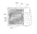
図1に示されているグリル56は、ケーシング40の前板46に取り付けられ、吹出口44を覆っている。グリル56には、外気を吹き出すため、図9に示されている開口部56aが多数形成されている。グリル56の左上部には、ガイド構造56bが樹脂製の板で形成されている。つまり、このような板状のガイド構造56bを形成するため、領域Ar1では、グリル56の桟56dと桟56dの間が塞がれた構造になっている。例えば、グリル56の形成時に、ガイド構造56bになる部分に開口部56aが形成されるのを避けて加工をすることによって、このガイド構造56bが形成される。射出成形によりグリル56を成形するときには、例えば、ガイド構造56bに対応する領域が塞がるように金型を作成する。このようにグリル56を製造すると、ガイド構造56bを別に形成するための工程を省くことができる。ここでは、ケーシング40をコンパクト化するためにガイド構造56bがケーシング40の外に形成されている。
正面から見て、ガイド構造56bが吹出口44に掛かる重なり部分56b2の面積が増加すれば、吸気口68aに導かれる外気の風量が増えるが、一方で室外熱交換器33に導かれる外気の風量の低下を招く。そのため、ガイド構造56bが吹出口44に掛かる面積は、両者に適切な風量が配分されるように設定される。
加湿ユニット60は、図2や図5などに示されているように、外気から吸湿するための吸湿部61と、放湿して空気を加湿するための放湿部62とを有する。
(3-5-1)吸湿部と放湿部
この加湿ユニット60においては、吸湿部61と放湿部62とは、図10に示されているような1枚の円盤状の加湿ロータ63によって構成されている。つまり、加湿ロータ63は、吸湿部61と放湿部62とを兼ねる吸放湿材である。この円盤状の加湿ロータ63は、ゼオライト等の焼成によって形成されたハニカム構造のゼオライトロータである。加湿ロータ63は、円盤の中心を回転軸として回転するように取り付けられ、加湿ロータ63の周囲に設けられているギア64に伝達されるロータ駆動用モータ(図示せず)の動力によって回転駆動される。
図7及び図8に示されているように、円盤状の加湿ロータ63の外周の全周囲は、包囲壁65,66によって包囲されている。この加湿ユニット60では、吸湿部61の外周が包囲壁65によって覆われ、放湿部62の外周が包囲壁66によって覆われている。
(3-5-3)吸湿用ダクト
吸湿部61の上部には、吸湿部61に外気を導くための吸湿用ダクト68が設けられている。吸湿用ダクト68を上から見ると、図4に示されているように、中心角αが180度より大きい扇形の吸湿部61の上を覆っている。
吸湿用ダクト68は、前面側に向かって開口していて前面側から外気を吸い込む吸気口68aを有している。吸湿用ダクト68は、図6に示されているように、吸気口68aに続く傾斜部68bが吸湿用ダクト68の上部に形成されており、そのため、側面から見ると吸湿用ダクト68が下方に向けて湾曲している形になる。このような下方に向け湾曲した構造を吸湿用ダクト68が持っているため、下方から上に向かって送風されてくる外気が吸湿用ダクト68の吸気口68aから入り易くなる。また、吸湿用ダクト68は、吸気口68aから後面側に進むに従って上下に広がっており、吸気口68aから後面側に進む外気は、後面側に進むに従って上下に広がり、吸湿部61の全体に行き渡り易くなる。吸湿用ダクト68は、図4に示されているように吸湿部61の全面を覆っており、下方に配置されている加湿ロータ63を上から下に向けて外気が通過する。
排気口69は、加湿ロータ63の下方にある。そして、この排気口69は、吸湿用ダクト68の上面からの投影部分にほぼ等しい領域を占める。排気口69の下方には、図6や図9に示されているように、プロペラ39bが配置されている。つまり、この排気口69は、プロペラ39bが回転するときに負圧になる空間70に対向していることになる。このような構成によって、ベルマウス52からプロペラ39bによって吹き出して吸気口68aに入った外気が、図9に二点鎖線で記されている経路を通って、負圧の空間70の方に引かれて排気口69から送風機室41に吹き出される。そのため、室外ファン39のみによって外気が吸湿部61に送られ、従来必要であった吸湿部61に外気を送るための専用のファンを省くことができる。
図10に示されているように、放湿部62から放湿させるために、加湿ロータ63の放湿部62の上方にヒータ71が設けられている。図11は、ヒータ71及びヒータ支持部材74を下方から見た底面図である。ヒータ71は、筒状の筐体の中に電熱線(図示せず)が設けられた構造を持ち、吸入口72から吸入されて加湿ロータ63に送られる外気を電熱線で加熱する。加湿ロータ63のハニカム構造の開口を加熱された空気が通り抜けるときに、加湿ロータ63からの放湿によって加湿用ダクト73の空気が加湿される。
ヒータ71は、図11に示されているように、ヒータ支持部材74の下側に取り付けられている。ヒータ支持部材74は、上面部74aと周囲の外壁部74bと固定板74cとを有し、上面と側面とが上面部74aと外壁部74bとで囲まれ下方が解放されている筒体である。ヒータ71の筐体及びヒータ支持部材74は、耐熱性を必要とするため板金によって形成されている。吸入口72は、ヒータ支持部材74の前面側かつ加湿ロータ63の下にあって、吸入口72から吸入されて加湿ロータ63を上に抜けた外気がヒータ71の筐体の中を前面側から後面側に向けて通過する。このとき、ヒータ71によって外気が加熱される。ヒータ71の筐体を通過した空気は、加湿ロータ63の上を通って後面側に進む。加湿ロータ63の後面側の下方が加湿用ダクト73(図5参照)に繋がっているので、加湿用ダクト73の上方に達した空気は、加湿ロータ63を下に向けて通過して加湿用ダクト73に吸い込まれる。加湿ロータ63は、ヒータ71によって温度が上昇した空気に晒されて放湿する。このように加湿ロータ63によって加湿された空気が加湿用ダクト73を経て室内機20へと導かれる。そのため、加湿ロータ63のうち、図10に示されているように、ヒータ支持部材74の下方が放湿部62になり、それ以外の部分が吸湿部61になる。加湿ロータ63は、上面から見て時計回りに回転しており、吸湿部61として機能した加湿ロータ63の部分が回転してヒータ支持部材74の下に来ると放湿部62として機能する。つまり、加湿ロータ63は、吸湿部61と放湿部62とを兼ねる吸放湿材である。
加湿用ダクト73は、上述のように、加湿ロータ63の下方後面側に位置していて室外熱交換器33の前方に位置するため、室外熱交換器33を通過する外気にとっての送風抵抗になる。また、ターボファン75も室外熱交換器33の前に配置されると送風抵抗を発生させる原因になるため、比較的占有容積の大きなターボファン75は、図2や図4に示されているように機械室42に設置されている。
プロペラ39bが加湿ユニット60の下方に配置されており、プロペラ39bの回転する領域のうち最も高い位置でも、室外熱交換器33の上端33bに比べると加湿ユニット60の高さ方向の大きさ分だけ下に位置することになる。そのため、室外熱交換器33の上端近傍を通過した外気は、プロペラ39bに向かって斜め下に向かって流れる。このような外気の流路を加湿用ダクト73ができるだけ妨げないように、加湿用ダクト73はターボファン75に近い方が室外熱交換器33の上端33bの高さと同じ位置にくるように、ターボファン75に向かって斜めに配置されている。加湿用ダクト73には、図2に示されているようにダンパ78が取り付けられており、加湿運転時における加湿用ダクト73における逆流つまりターボファン75側から加湿ロータ63へ流れる空気の流れを防止している。
(3-5-7)加湿ユニットの固定
図12は、加湿ユニット60の断面形状を示すための室外機30の部分断面図である。加湿ユニット60は、ファンモータ台53の上にビス53aで固定されている。また、加湿ユニット60の前方が前板46にまで達している。固定された状態では、加湿ユニット60は前後左右に移動しない。そのため、室外熱交換器33の前面33aと加湿ユニット60後面60bとの間に所定隙間Isが形成されている。この隙間Isは、後面60bに形成されているリブ60cによって確実に保たれる。また、吸湿用ダクト68の後面側には、傾斜部68cが形成され、図12に示されている包囲壁65は下方に行くに従って前方に張り出すように傾斜している傾斜部65cが設けられている。傾斜部65cを設けられて下方が図12に示されているように傾斜していると、外気の通りが良くなる。
また、加湿ユニット60の上部の傾斜部68cがあることによって、室外熱交換器33を前方に向かって通過して傾斜部68cに当たる外気については、加湿ユニット60に当たって左側の前方に進む。図4に示されているように、左側面側に進んだ外気は、室外熱交換器33と加湿ユニット60との空間41aから下に向けて流れ、プロペラ39bの方に向かう経路r3が形成される。そのため、この経路r3が形成されない場合に比べて、送風抵抗が低下する。
<第2実施形態>
第1実施形態では、吸湿用ダクト68の吸気口68aには、室外ファン39が発生した気流のうちのガイド構造56Abによって吸気口68aに導かれたもののみが吸気される。第1実施形態の構成は、室外ファン39の気流を十分に利用できるため、吸気される外気の量を確保し易い構成である。
(4)特徴
(4-1)
図9などに示されているように、室外熱交換器33から室外ファン39とベルマウス52とで仕切られる部分までの負圧空間70は、室外ファン39が回転しているときには負圧になる空間である。排気口69は、この負圧空間70に面しており、排気口69を挟んで、加湿ロータ63の在る側から負圧空間70に向かう気流が発生する。一方、ベルマウス52よりも前方は、吹出口44から吹き出される気流が発生する。室外機30には、図9や図13に示されているガイド構造56b,56Abで向きを変えた空気が吹出口44から吸気口68a、そして吸湿部61を経由して排気口69に抜ける経路r1が形成される。そのため、室外ファン39により外気を効率よく吸湿部61に導くことができ、吸湿機能が向上する。その結果、吸湿部61に外気を導くために従来設けられていた専用ファンや専用ファンのための駆動モータを省くことができる。なお、上記実施形態では、専用ファンなどが省かれる場合について説明したが、省かないまでも専用ファンや駆動モータを小型化できれば、加湿ユニット60のダウンサイジングを図ることができる。加湿ユニット60の小型化ができれば、室外機30のダウンサイジングも図れる。
図9に示されている第1実施形態の構成は、室外ファン39を経由してガイド構造56b,56Abに沿って導かれた空気のみを吸気口68aで吸気する構成である。このような構成では、室外ファン39によって発生する気流を十分に利用して外気を効率よく吸気口68aに導くことができる。
(4-3)
図13に示されているように、ガイド構造56Abに沿って経路r1(第1経路)で導かれる空気は、経路r4(第2経路)で導かれる空気を呼び込むために用いることができ、経路r4を使うことで経路r1(第1経路)の空気よりも湿度の高い空気を吸湿部に導入し易くなる。
(4-4)
図1、図9及び図13に示されているように、ガイド構造56b,56Abはグリル56,56Aに形成されており、グリル56,56Aとともにガイド構造56b,56Abが前板46に取り付けられている。つまり、ガイド構造56b,56Abの取り付けは、グリル56,56Aの取り付けによって行なうことができ、非常に簡単にガイド構造56b,56Abの取り付けが行える。
(4-5)
上述のように、ガイド構造56b,56Abは、グリル56,56Aに形成され、グリル56,56Aの開口部56aの打ち抜きがされなかった部分で構成されている。そのため、ガイド構造56b,56Abの成形が、グリル56,56Aの成形と同時に行なえるものとなっている。そのため、ガイド構造56b,56Abを形成するための専用の工程を付加しなくてもよく、ガイド構造56b,56Abを有する室外機30,30Aを安価に提供できる。
図9に示されているように、加湿ユニット60は、室外ファン39の上方に吸湿用ダクト68が配置されている。側面視において、吸気口68aから吸湿部61に外気を導く吸湿用ダクト68は、その上端と下端の中間を通る線を結ぶと下方に向けて湾曲していることが分かる。下方に向けて湾曲しているので、経路r1を通って下方から上がってくる外気を吸湿用ダクト68が吸気し易くなっており、吸湿部61へ供給される外気が増えて加湿性能が向上する。
(5)変形例
(5-1)
上記実施形態では、1台の室内機20に1台の室外機30が接続されているペア型の空気調和装置10について説明したが、本発明が適用できる空気調和装置のタイプはペア型には限られない。例えば、1台の室外機に複数台の室内機が接続されているマルチ型の空気調和装置にも本発明を適用することができる。
上記実施形態では、室外機30のケーシング40内が、送風機室41と機械室42の2つに分割されている場合について説明したが、内部に送風機室41が設けられているケーシング40であれば本発明の室外機を構成することができる。例えば、送風機室41と機械室42以外に仕切られた空間が形成されていてもよく、例えば機械室42が他の機能も含む他の室として設けられていてもよい。
(5-3)
上記実施形態では、室外熱交換器33が上面視L字型の形状を呈するものについて説明したが、本発明の室外機を構成する室外熱交換器は上述の形状には限られない。例えば、上面視I字型の形状を持つ室外熱交換器で構成することもできる。
図5に示されているように、排気用ダクト80が設けられてもよい。このような排気用ダクトが設けられる場合にも、室外熱交換器33の前面33aから排気用ダクトの後面との間に所定隙間Is以上の隙間Is2(図6参照)が設けられることが好ましい。また、排気用ダクト80の下方に傾斜部が設けられて、傾斜部80aによって送風抵抗が低下されるのが好ましい。
(5-5)
上記実施形態では、室外ファン39がプロペラ39bを持つものについて説明したが、プロペラ39bを持つものに限られない。プロペラ型以外のタイプの羽根を持つ室外ファンでも本発明の室外機を構成することができる。
上記実施形態では、吸湿部61が放湿部62よりも大きく、図4に示されているように、吸湿部61の中心角αが180度より大きい扇形になる場合について説明したが、吸湿部61と放湿部62の大きさは適宜設定できる。例えば。図13に示されるように、吸湿部61と放湿部62の大きさはほぼ等しくなるように、中心角をそれぞれ180度に設定することもできる。
(5-7)
上記実施形態では、吸湿部61に外気を導くための専用のファンやそのファンを駆動するためのモータを省いているが、従来よりも小型化された専用ファンや専用ファン用のモータを取り付けてもよい。そのような場合であっても、室外ファン39によって吸湿部61に送風されるため、吸湿部61に外気を導くためだけの専用ファンや専用ファン用のモータを従来に比べて小型化できる分だけ従来よりも室外機をコンパクト化できる。
上記実施形態では、仕切板43によって放湿部62とターボファン75との間を仕切る場合について説明したが、図14及び図15に示されている仕切板43によって吸湿部61と放湿部62との間で仕切るように構成することもできる。図14及び図15に示されているように、吸湿部61と放湿部62との境に仕切板43を配置することによって、放湿部62と加湿用ダクト73とターボファン75とを機械室42に設置するように構成することができる。それにより、室外熱交換器33を通過した外気によって放湿部62が冷やされるのを防ぐことができる。また、ターボファン75と加湿用ダクト73の一部だけでなく、放湿部62及び加湿用ダクト73の全体が室外熱交換器33を通過した外気の通路から外れるので、これらによる通風抵抗の増加を低減することができる。このような変形例においても、ガイド構造の位置を吸気口68aの位置にあわせて仕切板43の方へ移動することによって上述のガイド構造を適用することができる。
また、ターボファン75が、その回転軸の延びる方向を前後に向けて設置される場合を例に挙げて説明したが、ターボファン75の設置方向はこの例に限られるものではない。例えば、図15に示されているように、回転軸の延びる方向をケーシング40の長手方向である左右方向に一致させるように構成することもできる。このように回転軸の延びる方向をケーシング40の長手方向に一致させることにより、ケーシングの長手方向の長さを短縮し易くなる。
(1)空気調和装置及び室外機の構成の概要
次に、図17乃至図23を用いて第3実施形態に係る空気調和装置の室外機について説明する。図17乃至図23に示されている第3実施形態に係る室外機30Bが組み込まれた空気調和装置の構成の概要は、図17に示されているように、第1実施形態において図2を用いて説明した空気調和装置10の構成の概要とほぼ同じであるが、一部変更されている。第3実施形態の室外機30Bも、第1実施形態の室外機30と同様に、ケーシング40Bと仕切板43Bとを備えており、図17と図20に示されているように、ケーシング40Bの内部空間が仕切板43Bによって送風機室41Bと機械室42Bとに分けられている。室外機30Bには、冷媒回路を構成するため、室外機30と同様に圧縮機31、四路切換弁32、室外熱交換器33、電動弁34、フィルタ35、アキュムレータ36、液閉鎖弁37及びガス閉鎖弁38が設けられている。また、図20に示されているように、ファンモータ39Baによってプロペラ39Bbが駆動される室外ファン39Bが室外熱交換器33の下流側に設けられている。このプロペラ39Bbは正面から見て反時計回りに回転する。そして、加湿ユニット60Bは、送風機室41Bの空間内に設置され、室外ファン39Bの上方に配置されている。
図17に示されているように、加湿ユニット60Bが吸湿部61と放湿部62とを有する点は、第1実施形態の加湿ユニット60と同じである。また、加湿ユニット60Bが、図10に示されているような1枚の円盤状の加湿ロータ63及びヒータ71を有する点、図9に示されている吸湿用ダクト68、図10に示されている排気口69及び図7に示されている吸入口72に相当する吸入口72B(図20参照)を有する点、並びに図7に示されている加湿用ダクト73及びターボファン75に相当するターボファン75Bを有する点は、第1実施形態の加湿ユニット60と同様である。
加湿ユニット60Bの吸入口72Bが加湿ユニット60の吸入口72と異なる点はその形状と大きさであり、吸入口72Bから吸入された外気が加湿ロータ63に送られる構造は加湿ユニット60Bも加湿ユニット60と同じである。また、加湿ユニット60のターボファン75の配置が縦置きであるのに対し、加湿ユニット60Bのターボファン75Bは横置きの配置となっている。つまり、ターボファン75の羽根車の回転軸が前後方向に延びるのに対し、ターボファン75Bの羽根車の回転軸は上下方向に延びている。ターボファン75Bは、図20に示されているようにプロペラ39Bbの上方の送風機室41Bに配置されているが、横置きとすることで通風抵抗の増加を抑えられるように送風機室41Bの内部に取り付けられている。
(3)室外熱交換器と加湿ユニットの配置関係
図20には、室外熱交換器33の前に配置されている加湿ユニット60Bが示されている。室外熱交換器33の前に加湿ユニット60Bが剥き出しで配置されているのが、この室外機30Bの特徴の一つである。加湿ユニット60Bの上面60Baの位置の高さは、室外熱交換器33の上端33b(頂部)の高さに一致する。そのため、この加湿ユニット60Bには、比較的複雑な外観をそのままに、できるだけ容積が小さくなる形状が与えられている。ここでは、加湿ユニット60Bの上面60Baの位置の高さを室外熱交換器33の上端33bの高さに一致させているが、必ずしも一致させる必要はなく、室外熱交換器33の前に加湿ユニット60Bが剥き出しで配置されることで室外機30Bのコンパクト化が図られている。
図18は室外機30Bの正面図であり、図19は室外機30Bの斜視図であり、図19には、図18の室外機30Bからグリル56などが取り外された状態が示されている。室外機30Bのケーシング40Bは、前板46B、右側板47、天板48及び底板49を備えている。ケーシング40Bの左側面にもケーシング40と同様に、L字型の室外熱交換器33の左側面部に正対して、格子形状に成形されている左側板が取り付けられている。また、ケーシング40と同様に、ケーシング40Bの送風機室41Bの後側には室外熱交換器33の後面部を覆う保護金網が取り付けられ、送風機室41Bの後側が開放されている。
前板46Bには、図19に示されている円形の吹出口44が形成されており、吹出口44Bの周囲にリング状のベルマウス52が取り付けられている。プロペラ39Bbの一部がこのベルマウス52で囲まれた空間内に入るように配置されている。
(5)グリル
図21には、ケーシング40Bに取り付けられているグリル56Bを、ケーシング40Bから室外熱交換器33及び室外ファン39Bなどを取り除いて背面から見た状態が示されている。そして、図22はグリル56Bの背面図であり、図23はグリル56Bを背面の斜め上方から見た斜視図である。図18に示されているグリル56Bは、ケーシング40Bの前板46Bに取り付けられ、吹出口44を覆っている。グリル56Bには、桟56dと桟56dの間に開口部56aが多数形成されている。グリル56Bの上部には、ガイド構造56Bbが樹脂製の板で形成されている。
図21に示されているように、室外機30Bをみると、ガイド構造56Bbは、前板46Bとの重なり部分56Bb1及び吹出口44との重なり部分56Bb2を有していることが分かる。前板46Bとの重なり部分56Bb1と前板46Bとの間の空間が通路になり、吹出口44との重なり部分56Bb2で向きを変えた外気が前板46Bとの重なり部分56Bb1及び前板46Bで形成される通路を通って吸気口68aに導かれる。吹出口44との重なり部分56Bb2の面積が増加すれば、吸気口68aに導かれる外気の風量が増える一方、吹出口44との重なり部分56Bb2で送風抵抗が増加して室外熱交換器33に導かれる外気の風量の低下を招く。そのため、吹出口44との重なり部分56Bb2の面積は、両者に適切な風量が配分されるように設定される。
グリル56Bの内面において吸入用開口部56pの下にはリブ56rが形成されている。リブ56rは、表面が滑らかな板状に成形されており、室外ファン39Bの回転方向に延びている。言い換えると、室外ファン39Bのプロペラ39Bbの回転中心39Bb1から放射状に延びる直線に対してほぼ直交する方向にリブ56rが延びている。図23における二点差線で囲まれた領域Ar2に吸気口68aが対向している。このリブ56rと前板56Bとガイド構造56Bbとで、図23に示されている経路r5の3方が囲まれたチェネルが形成される。このチャネルにより、室外ファン39Bのプロペラ39Bbの回転方向に吹出口44から旋回して吹出される外気を経路r5に沿ってスムーズに導くことができる。
(6-1)
図9などを用いて説明した第1実施形態と同様に、室外熱交換器33から室外ファン39Bとベルマウス52とで仕切られる部分までの空間は、室外ファン39Bが回転しているときには負圧になる空間である。排気口69は、この負圧空間に面しており、排気口69を挟んで、加湿ロータ63の在る側から負圧空間に向かう気流が発生する。一方、ベルマウス52よりも前方は、吹出口44から吹き出される気流が発生する。
室外機30Bには、図22及び図23に示されているガイド構造56Bbで向きを変えた空気が吹出口44から吸気口68a、そして吸湿部61を経由して排気口69に抜ける経路r5が形成される。そのため、室外ファン39Bにより外気を効率よく吸湿部61に導くことができ、吸湿機能が向上する。その結果、吸湿部61に外気を導くために従来設けられていた専用ファンや専用ファンのための駆動モータを省くことができる。なお、上記実施形態では、専用ファンなどが省かれる場合について説明したが、省かないまでも専用ファンや駆動モータを小型化できれば、加湿ユニット60Bのダウンサイジングを図ることができる。加湿ユニット60Bの小型化ができれば、室外機30Bのダウンサイジングも図れる。
図23に示されている第3実施形態の構成は、室外ファン39Bを経由してガイド構造56Bbに沿う経路r5で導かれた空気のみを吸気口68aで吸気する構成である。このような構成では、室外ファン39によって発生する気流を十分に利用して外気を効率よく吸気口68aに導くことができる。
第3実施形態では、図13に示されたガイド構造56Abに沿って経路r1(第1経路)で導かれる空気が、経路r4(第2経路)で導かれる空気を呼び込むために用いる構成については説明されていないが、第3実施形態の吸気口68aに対向するガイド構造56Bbに第2実施形態の開口部56Abaように開口部を設けて経路r4に相当する経路を作り、経路r1の空気よりも湿度の高い空気を吸湿部61に導入するように構成してもよい。
図21乃至図23に示されているように、ガイド構造56Bbはグリル56Bに形成されており、グリル56Bとともにガイド構造56Bbが前板46Bに取り付けられている。つまり、ガイド構造56Bbの取り付けは、グリル56Bの取り付けによって行なうことができ、非常に簡単にガイド構造56Bbの取り付けが行える。
上記第3実施形態では、グリル56Bとガイド構造56Bbを一体的に形成したものを示したが、グリル56Bとガイド構造56Bbとが分離するものであってもよい。また、上記実施形態のようにグリル56Bを介して間接的にガイド構造56Bbが前板46Bに取り付けられる場合だけでなく、ガイド構造56Bbが直接前板46Bに取り付けられるものであってもよい。
(6-4)
図20に示されているように、加湿ユニット60Bも加湿ユニット60と同様に、室外ファン39Bの上方に吸湿用ダクト68が配置されている。加湿ユニット60Bの吸湿用ダクト68も加湿ユニット60の吸湿用ダクト68と同様に、その上端と下端の中間を通る線を結ぶと下方に向けて湾曲している。そのため、経路r1を通って下方から上がってくる外気を吸湿用ダクト68が吸気し易くなっており、吸湿部61へ供給される外気が増えて加湿性能が向上する。
図22及び図23に示されているリブ56rは、ガイド構造56Bbと前板46Bとの間に配置されてガイド構造56Bbと前板46Bに挟まれた空間を仕切る仕切部材である。リブ56rが設けられることによって吹出口44から吸気口68aに導かれる空気の流れは、前板46Bとガイド構造56Bbとリブ56rとで三方を囲むチャネルの中を通過する。リブ56r(仕切部材)を設けることによって形成されるチャネルにより空気の流れが囲まれるので、この通路から外れて吸気口68aに到達しない空気の流れが抑制されるので、効率良く吸気口68aに空気を送り込むことができる。なお、仕切部材は、不要な方向への空気の流れを抑制するためには、例えば前板46Bに接触して隙間なく空間を仕切れる方が好ましいが、必ずしも前板46Bに接触している必要はない。
(7)変形例
(7-1)
上記第3実施形態では、図17に示されているように、1台の室内機20に1台の室外機30Bが接続されているペア型の空気調和装置10について説明したが、本発明が適用できる空気調和装置のタイプはペア型には限られない。例えば、1台の室外機に複数台の室内機が接続されているマルチ型の空気調和装置にも本発明を適用することができる。
上記第3実施形態では、室外機30Bのケーシング40B内が、送風機室41Bと機械室42Bの2つに分割されている場合について説明したが、内部に送風機室41Bが設けられているケーシング40Bであれば本発明の室外機を構成することができ、送風機室41Bと機械室42以外に仕切られた空間が形成されていてもよく、例えば機械室42が他の機能も含む他の室として設けられていてもよい。
(7-3)
上記第3実施形態では、室外熱交換器33が上面視L字型の形状を呈するものについて説明したが、本発明の室外機を構成する室外熱交換器は上述の形状には限られない。例えば、上面視I字型の形状を持つ室外熱交換器で構成することもできる。
加湿ユニット60Bについても、図5に示されている加湿ユニット60と同様の排気用ダクト80が設けられてもよい。
(7-5)
上記第3実施形態では、室外ファン39Bがプロペラ39Bbを持つものについて説明したが、プロペラ39Bbを持つものに限られない。プロペラ型以外のタイプの羽根を持つ室外ファンでも本発明の室外機を構成することができる。
(7-6)
上記第3実施形態では、吸湿部61に外気を導くための専用のファンやそのファンを駆動するためのモータを省いているが、従来よりも小型化された専用ファンや専用ファン用のモータを取り付けてもよい。そのような場合であっても、室外ファン39Bによって吸湿部61への送風が行われるため、吸湿部61に外気を導くためだけの専用ファンや専用ファン用のモータを従来に比べて小型化できる分だけ従来よりも室外機をコンパクト化できる。
上記第3実施形態では、仕切板43Bによってターボファン75Bと給気ダクト18の間を仕切る場合について説明したが、上記第1実施形態又は第2実施形態で説明したように、他の場所を仕切ってもよい。
(7-8)
上記第3実施形態のグリル56Bは、図22及び図23に示されているように、リブ56sがガイド構造56Bbの吹出口44との重なり部分56Bb2を除く部位にしか形成されていない。しかし、ガイド構造は、室外ファンの回転中心に近い端部近傍に吸気口から吹出口の方向に向かう空気の流れを妨げるバッフル部材を有していてもよい。例えば図22に示されているグリル56Bに代えて図24に示されているグリル56Cを用い、吸気口68aから吹出口44の方向に向かう空気の流れを妨げるため、室外ファン39Bの回転中心39Bb1に近いガイド構造56Cbの端部56Cb3に、リブ56tをバッフル部材として形成してもよい。この場合には、リブ56tで吸気口68aから吹出口44の方向に向かう空気の流れを抑制することができるので、グリル56Bに比べて吸気口68aに導かれる空気の量が増加する。なお、グリル56Cは、リブ56sの構造を除いてグリル56Bと同様の構造を有する。また、バッフル部材は、リブ56tのようなリブ構造に限られるものではなく、プラスチックフィルムやスポンジなどの他の部材で構成することもできるが、リブ56tのようにグリル56Bと一体成形できる構造が好ましい。
上記第3実施形態のグリル56Cは、図24に示されているように、ガイド構造56Cbの内面が平坦に成形されている。しかし、ガイド構造と前板との間に配置されかつ吹出口から吸気口に向かって滑らかに延びる整流部材が設けられてもよい。例えば図22に示されているグリル56Bに代えて図25及び図26に示されているグリル56Dを用い、ガイド構造56Dbの内面、つまりガイド構造56Dbと前板56Bとの間に配置されかつ吹出口44から吸気口68aに向かって滑らかに延びるリブ56uを整流部材として設けてもよい。このような構造にすれば、リブ56uに沿って吸気口68aに向かって空気が流れるため空気の流れが整えられ、吸気口68aに向かう空気の流れに起因して生じる音を低く抑えることができる。なお、グリル56Dは、リブ56s及びリブ56uの構造を除いてグリル56Bと同様の構造を有する。また、整流部材は、リブ56uのようなリブ構造に限られるものではないが、リブ56uのようにグリル56Bと一体成形できる構造が好ましい。
20 室内機
30,30B 室外機
33 室外熱交換器
39,39B 室外ファン
40,40B ケーシング
41,41B 送風機室
56,56A,56B,56C,56D グリル
60,60B 加湿ユニット
63 加湿ロータ
68 吸湿用ダクト
73 加湿用ダクト
75,75B ターボファン
Claims (10)
- 外気が通過する送風機室(41)を有するケーシング(40)と、
前記送風機室に設置され、外気との間で熱交換を行う室外熱交換器(33)と、
前記送風機室に設置され、前記室外熱交換器に外気を送風する室外ファン(39,39B)と、
前記室外ファンが送風する一部の空気の向きを変えるガイド構造(56b,56Ab,56Bb,56Cb,56Db)と、
外気から吸湿する吸湿部(61)と、放湿して空気を加湿する放湿部(62)と、前記吸湿部に供給される外気の吸気口(68a)及び排気口(69)とを有し、前記室外ファン周囲の負圧空間に面して前記排気口が配置され、前記ガイド構造で向きを変えた空気が前記吸気口から前記吸湿部を経由して前記排気口に抜けるように構成されている加湿ユニット(60)と、
を備える、空気調和装置の室外機。 - 前記吸気口から吸気される全ての空気が前記室外ファンを経由して前記ガイド構造(56b,56Bb,56Cb,56Db)に沿って導かれた空気である、
請求項1に記載の空気調和装置の室外機。 - 前記加湿ユニットは、前記吸気口で、前記ガイド構造に沿う第1経路(r1)で導かれる空気と前記第1経路と異なる第2経路(r4)で導かれる空気とを合わせて吸気する、
請求項1に記載の空気調和装置の室外機。 - 前記ケーシングは、前記室外ファンにより送風される外気が吹き出される吹出口を有する前板(46,46B)を備え、
前記ガイド構造は、前記吹出口の一部を覆うように前記前板に取り付けられている、
請求項1から3のいずれか一項に記載の空気調和装置の室外機。 - 前記ケーシングは、前記前板に取り付けられ、前記前板の吹出口を覆うグリル(56,56Ab,56Bb,56Cb,56Db)をさらに有し、
前記ガイド構造は、前記グリルに形成されている、
請求項4に記載の空気調和装置の室外機。 - 前記ガイド構造(56Bb)と前記前板(56B)との間に配置されて前記ガイド構造と前記前板に挟まれた空間を仕切ることにより、前記吹出口(44)から前記吸気口(68a)に向かう空気の流れを囲むチャネルを形成するための仕切部材(56r)をさらに備える、
請求項4又は請求項5に記載の空気調和装置の室外機。 - 前記仕切部材は、前記室外ファンの回転方向に延びている、
請求項6に記載の空気調和装置の室外機。 - 前記ガイド構造(56Cb)は、前記室外ファンの回転中心に近い端部近傍に前記吸気口から前記吹出口の方向に向かう空気の流れを妨げるバッフル部材(56t)を有する、
請求項4から7のいずれか一項に記載の空気調和装置の室外機。 - 前記ガイド構造(56Db)と前記前板との間に配置されかつ前記吹出口から前記吸気口に向かって延びる整流部材(56u)をさらに備える、
請求項4から請求項8のいずれか一項に記載の空気調和装置の室外機。 - 前記加湿ユニットは、前記室外ファンの上方に配置されている、前記吸気口から前記吸湿部に外気を導くための吸湿用ダクト(68)をさらに有し、側面視において前記吸湿用ダクトが下方に向けて湾曲している、
請求項1から9のいずれか一項に記載の空気調和装置の室外機。
Priority Applications (5)
| Application Number | Priority Date | Filing Date | Title |
|---|---|---|---|
| KR1020137034553A KR101401186B1 (ko) | 2011-06-01 | 2012-05-31 | 공기 조화 장치의 실외기 |
| RU2013157895/12A RU2536029C1 (ru) | 2011-06-01 | 2012-05-31 | Наружный блок для кондиционера воздуха |
| CN201280026099.1A CN103582785B (zh) | 2011-06-01 | 2012-05-31 | 空调装置的室外机 |
| EP12793412.3A EP2716984B1 (en) | 2011-06-01 | 2012-05-31 | Outdoor unit for air conditioner |
| ES12793412.3T ES2574480T3 (es) | 2011-06-01 | 2012-05-31 | Unidad exterior de acondicionador de aire |
Applications Claiming Priority (2)
| Application Number | Priority Date | Filing Date | Title |
|---|---|---|---|
| JP2011123408 | 2011-06-01 | ||
| JP2011-123408 | 2011-06-01 |
Publications (1)
| Publication Number | Publication Date |
|---|---|
| WO2012165528A1 true WO2012165528A1 (ja) | 2012-12-06 |
Family
ID=47259380
Family Applications (1)
| Application Number | Title | Priority Date | Filing Date |
|---|---|---|---|
| PCT/JP2012/064036 Ceased WO2012165528A1 (ja) | 2011-06-01 | 2012-05-31 | 空気調和装置の室外機 |
Country Status (7)
| Country | Link |
|---|---|
| EP (1) | EP2716984B1 (ja) |
| JP (1) | JP5234205B2 (ja) |
| KR (1) | KR101401186B1 (ja) |
| CN (1) | CN103582785B (ja) |
| ES (1) | ES2574480T3 (ja) |
| RU (1) | RU2536029C1 (ja) |
| WO (1) | WO2012165528A1 (ja) |
Cited By (3)
| Publication number | Priority date | Publication date | Assignee | Title |
|---|---|---|---|---|
| US20150068711A1 (en) * | 2013-09-11 | 2015-03-12 | Daikin Industries, Ltd. | Duct-type indoor unit of air conditioner |
| CN117663298A (zh) * | 2022-08-29 | 2024-03-08 | 芜湖美智空调设备有限公司 | 一种空调外机和空调 |
| EP4455302A1 (en) | 2023-04-25 | 2024-10-30 | Technische Universität München | Programmable nuclease resistance of nucleic acid assemblies |
Families Citing this family (15)
| Publication number | Priority date | Publication date | Assignee | Title |
|---|---|---|---|---|
| JP2015098996A (ja) * | 2013-11-20 | 2015-05-28 | ダイキン工業株式会社 | 空調室外ユニット |
| JP5796618B2 (ja) * | 2013-11-20 | 2015-10-21 | ダイキン工業株式会社 | 空調室外ユニット |
| WO2016098726A1 (ja) * | 2014-12-18 | 2016-06-23 | ダイキン工業株式会社 | 空調機の室外ユニット |
| JP6119823B2 (ja) * | 2014-12-18 | 2017-04-26 | ダイキン工業株式会社 | 空調機の室外ユニット |
| JP6540277B2 (ja) * | 2015-06-29 | 2019-07-10 | 株式会社富士通ゼネラル | 空気調和機の室外機 |
| EP3910259A1 (en) | 2016-02-26 | 2021-11-17 | LG Electronics Inc. | Air cleaner |
| EP3211337B1 (en) | 2016-02-26 | 2020-09-23 | LG Electronics Inc. | Air cleaner |
| CN111156622B (zh) | 2016-02-26 | 2022-04-26 | Lg电子株式会社 | 空气清洁器 |
| JP6777753B2 (ja) * | 2016-02-26 | 2020-10-28 | エルジー エレクトロニクス インコーポレイティド | 空気清浄機 |
| US10518205B2 (en) | 2016-02-26 | 2019-12-31 | Lg Electronics Inc. | Air cleaner |
| US11065575B2 (en) * | 2018-07-05 | 2021-07-20 | Molecule Works Inc. | Membrane device for water and energy exchange |
| JP7146610B2 (ja) * | 2018-12-17 | 2022-10-04 | シャープ株式会社 | 空気調和機 |
| CN212132769U (zh) | 2019-12-31 | 2020-12-11 | 特灵国际有限公司 | 设有挡风板的hvacr系统 |
| CN113531675A (zh) * | 2021-06-30 | 2021-10-22 | 青岛海尔空调器有限总公司 | 空调室外机、空调 |
| WO2024127447A1 (ja) * | 2022-12-12 | 2024-06-20 | 三菱電機株式会社 | 室外機、および冷凍サイクル装置 |
Citations (6)
| Publication number | Priority date | Publication date | Assignee | Title |
|---|---|---|---|---|
| JP2002089896A (ja) * | 2000-09-12 | 2002-03-27 | Daikin Ind Ltd | 空気調和機 |
| JP2002098373A (ja) * | 2000-09-26 | 2002-04-05 | Daikin Ind Ltd | 空気調和機 |
| JP2004353898A (ja) | 2003-05-27 | 2004-12-16 | Mitsubishi Electric Corp | 空気調和機、空気調和機の運転方法 |
| JP2005321116A (ja) * | 2004-05-06 | 2005-11-17 | Matsushita Electric Ind Co Ltd | 加湿装置および空気調和機 |
| JP2008241212A (ja) | 2007-03-28 | 2008-10-09 | Toshiba Carrier Corp | 空気調和機 |
| JP2010043848A (ja) * | 2008-07-18 | 2010-02-25 | Daikin Ind Ltd | 空気調和機 |
Family Cites Families (9)
| Publication number | Priority date | Publication date | Assignee | Title |
|---|---|---|---|---|
| JPH0526476A (ja) * | 1991-07-19 | 1993-02-02 | Daikin Ind Ltd | 空気調和機のインバータ冷却装置 |
| RU2259515C2 (ru) * | 2001-02-28 | 2005-08-27 | Дэу Электроникс Корпорейшн | Установка для кондиционирования воздуха, имеющая обогащающее кислородом устройство |
| CN2522775Y (zh) * | 2001-11-27 | 2002-11-27 | 珠海格力电器股份有限公司 | 具有加湿换气功能的空调器 |
| JP2003164721A (ja) * | 2001-11-29 | 2003-06-10 | Daikin Ind Ltd | 空気調和装置の加湿ユニット |
| CN2519889Y (zh) * | 2001-12-20 | 2002-11-06 | 丁静 | 自动调节湿度空调装置 |
| CN2531298Y (zh) * | 2002-03-14 | 2003-01-15 | 伊莱电器(杭州)有限公司 | 带无水加湿装置的空调器 |
| JP2004053198A (ja) * | 2002-07-23 | 2004-02-19 | Daikin Ind Ltd | 空気調和機の室外機および空気調和機 |
| JP3668786B2 (ja) * | 2003-12-04 | 2005-07-06 | ダイキン工業株式会社 | 空気調和装置 |
| JP2007101058A (ja) * | 2005-10-04 | 2007-04-19 | Daikin Ind Ltd | 加湿ユニット |
-
2012
- 2012-05-29 JP JP2012121527A patent/JP5234205B2/ja not_active Expired - Fee Related
- 2012-05-31 RU RU2013157895/12A patent/RU2536029C1/ru active
- 2012-05-31 ES ES12793412.3T patent/ES2574480T3/es active Active
- 2012-05-31 KR KR1020137034553A patent/KR101401186B1/ko active Active
- 2012-05-31 CN CN201280026099.1A patent/CN103582785B/zh active Active
- 2012-05-31 WO PCT/JP2012/064036 patent/WO2012165528A1/ja not_active Ceased
- 2012-05-31 EP EP12793412.3A patent/EP2716984B1/en active Active
Patent Citations (6)
| Publication number | Priority date | Publication date | Assignee | Title |
|---|---|---|---|---|
| JP2002089896A (ja) * | 2000-09-12 | 2002-03-27 | Daikin Ind Ltd | 空気調和機 |
| JP2002098373A (ja) * | 2000-09-26 | 2002-04-05 | Daikin Ind Ltd | 空気調和機 |
| JP2004353898A (ja) | 2003-05-27 | 2004-12-16 | Mitsubishi Electric Corp | 空気調和機、空気調和機の運転方法 |
| JP2005321116A (ja) * | 2004-05-06 | 2005-11-17 | Matsushita Electric Ind Co Ltd | 加湿装置および空気調和機 |
| JP2008241212A (ja) | 2007-03-28 | 2008-10-09 | Toshiba Carrier Corp | 空気調和機 |
| JP2010043848A (ja) * | 2008-07-18 | 2010-02-25 | Daikin Ind Ltd | 空気調和機 |
Non-Patent Citations (1)
| Title |
|---|
| See also references of EP2716984A4 * |
Cited By (4)
| Publication number | Priority date | Publication date | Assignee | Title |
|---|---|---|---|---|
| US20150068711A1 (en) * | 2013-09-11 | 2015-03-12 | Daikin Industries, Ltd. | Duct-type indoor unit of air conditioner |
| US10480817B2 (en) * | 2013-09-11 | 2019-11-19 | Daikin Industries, Ltd. | Duct-type indoor unit of air conditioner |
| CN117663298A (zh) * | 2022-08-29 | 2024-03-08 | 芜湖美智空调设备有限公司 | 一种空调外机和空调 |
| EP4455302A1 (en) | 2023-04-25 | 2024-10-30 | Technische Universität München | Programmable nuclease resistance of nucleic acid assemblies |
Also Published As
| Publication number | Publication date |
|---|---|
| JP2013011435A (ja) | 2013-01-17 |
| RU2536029C1 (ru) | 2014-12-20 |
| CN103582785B (zh) | 2015-07-29 |
| JP5234205B2 (ja) | 2013-07-10 |
| EP2716984A4 (en) | 2014-06-18 |
| ES2574480T3 (es) | 2016-06-20 |
| EP2716984A1 (en) | 2014-04-09 |
| EP2716984B1 (en) | 2016-03-16 |
| CN103582785A (zh) | 2014-02-12 |
| KR20140009589A (ko) | 2014-01-22 |
| KR101401186B1 (ko) | 2014-05-28 |
Similar Documents
| Publication | Publication Date | Title |
|---|---|---|
| JP5234205B2 (ja) | 空気調和装置の室外機 | |
| CN105745499B (zh) | 空调室外单元 | |
| JP2012251692A (ja) | 空気調和装置の室外機 | |
| JP5790162B2 (ja) | 空気調和装置の室外機 | |
| JP5672284B2 (ja) | 空気調和装置の室外機 | |
| JP5532100B2 (ja) | 空気調和装置の室外機 | |
| CN105579781B (zh) | 空调室外单元 | |
| JP5533970B2 (ja) | 空気調和装置の室外機 | |
| JP5532099B2 (ja) | 空気調和装置の室外機 | |
| JP2015098997A (ja) | 加湿装置 | |
| JP5659954B2 (ja) | 空気調和装置の室外機 | |
| JP5862058B2 (ja) | 空気調和装置の室外機 | |
| JP2012251691A (ja) | 空気調和装置の室外機 | |
| JP5910697B2 (ja) | 空気調和装置の室外機 | |
| JP2015098996A (ja) | 空調室外ユニット | |
| CN203478459U (zh) | 室外机 | |
| JP2015098992A (ja) | 空調室外ユニット | |
| WO2015046013A1 (ja) | 空調室外ユニット | |
| JP2023080694A (ja) | 換気装置 |
Legal Events
| Date | Code | Title | Description |
|---|---|---|---|
| 121 | Ep: the epo has been informed by wipo that ep was designated in this application |
Ref document number: 12793412 Country of ref document: EP Kind code of ref document: A1 |
|
| NENP | Non-entry into the national phase |
Ref country code: DE |
|
| WWE | Wipo information: entry into national phase |
Ref document number: 2012793412 Country of ref document: EP |
|
| ENP | Entry into the national phase |
Ref document number: 20137034553 Country of ref document: KR Kind code of ref document: A |
|
| ENP | Entry into the national phase |
Ref document number: 2013157895 Country of ref document: RU Kind code of ref document: A |