WO2012165220A1 - バッテリ装置、制御方法、及び電動車両 - Google Patents
バッテリ装置、制御方法、及び電動車両 Download PDFInfo
- Publication number
- WO2012165220A1 WO2012165220A1 PCT/JP2012/063033 JP2012063033W WO2012165220A1 WO 2012165220 A1 WO2012165220 A1 WO 2012165220A1 JP 2012063033 W JP2012063033 W JP 2012063033W WO 2012165220 A1 WO2012165220 A1 WO 2012165220A1
- Authority
- WO
- WIPO (PCT)
- Prior art keywords
- battery
- authentication information
- power
- power line
- electronic device
- Prior art date
Links
Images


Classifications
-
- B—PERFORMING OPERATIONS; TRANSPORTING
- B60—VEHICLES IN GENERAL
- B60L—PROPULSION OF ELECTRICALLY-PROPELLED VEHICLES; SUPPLYING ELECTRIC POWER FOR AUXILIARY EQUIPMENT OF ELECTRICALLY-PROPELLED VEHICLES; ELECTRODYNAMIC BRAKE SYSTEMS FOR VEHICLES IN GENERAL; MAGNETIC SUSPENSION OR LEVITATION FOR VEHICLES; MONITORING OPERATING VARIABLES OF ELECTRICALLY-PROPELLED VEHICLES; ELECTRIC SAFETY DEVICES FOR ELECTRICALLY-PROPELLED VEHICLES
- B60L53/00—Methods of charging batteries, specially adapted for electric vehicles; Charging stations or on-board charging equipment therefor; Exchange of energy storage elements in electric vehicles
- B60L53/10—Methods of charging batteries, specially adapted for electric vehicles; Charging stations or on-board charging equipment therefor; Exchange of energy storage elements in electric vehicles characterised by the energy transfer between the charging station and the vehicle
- B60L53/14—Conductive energy transfer
-
- B—PERFORMING OPERATIONS; TRANSPORTING
- B60—VEHICLES IN GENERAL
- B60L—PROPULSION OF ELECTRICALLY-PROPELLED VEHICLES; SUPPLYING ELECTRIC POWER FOR AUXILIARY EQUIPMENT OF ELECTRICALLY-PROPELLED VEHICLES; ELECTRODYNAMIC BRAKE SYSTEMS FOR VEHICLES IN GENERAL; MAGNETIC SUSPENSION OR LEVITATION FOR VEHICLES; MONITORING OPERATING VARIABLES OF ELECTRICALLY-PROPELLED VEHICLES; ELECTRIC SAFETY DEVICES FOR ELECTRICALLY-PROPELLED VEHICLES
- B60L53/00—Methods of charging batteries, specially adapted for electric vehicles; Charging stations or on-board charging equipment therefor; Exchange of energy storage elements in electric vehicles
- B60L53/60—Monitoring or controlling charging stations
- B60L53/65—Monitoring or controlling charging stations involving identification of vehicles or their battery types
-
- B—PERFORMING OPERATIONS; TRANSPORTING
- B60—VEHICLES IN GENERAL
- B60R—VEHICLES, VEHICLE FITTINGS, OR VEHICLE PARTS, NOT OTHERWISE PROVIDED FOR
- B60R16/00—Electric or fluid circuits specially adapted for vehicles and not otherwise provided for; Arrangement of elements of electric or fluid circuits specially adapted for vehicles and not otherwise provided for
- B60R16/02—Electric or fluid circuits specially adapted for vehicles and not otherwise provided for; Arrangement of elements of electric or fluid circuits specially adapted for vehicles and not otherwise provided for electric constitutive elements
- B60R16/03—Electric or fluid circuits specially adapted for vehicles and not otherwise provided for; Arrangement of elements of electric or fluid circuits specially adapted for vehicles and not otherwise provided for electric constitutive elements for supply of electrical power to vehicle subsystems or for
- B60R16/033—Electric or fluid circuits specially adapted for vehicles and not otherwise provided for; Arrangement of elements of electric or fluid circuits specially adapted for vehicles and not otherwise provided for electric constitutive elements for supply of electrical power to vehicle subsystems or for characterised by the use of electrical cells or batteries
-
- B—PERFORMING OPERATIONS; TRANSPORTING
- B62—LAND VEHICLES FOR TRAVELLING OTHERWISE THAN ON RAILS
- B62H—CYCLE STANDS; SUPPORTS OR HOLDERS FOR PARKING OR STORING CYCLES; APPLIANCES PREVENTING OR INDICATING UNAUTHORIZED USE OR THEFT OF CYCLES; LOCKS INTEGRAL WITH CYCLES; DEVICES FOR LEARNING TO RIDE CYCLES
- B62H5/00—Appliances preventing or indicating unauthorised use or theft of cycles; Locks integral with cycles
- B62H5/20—Appliances preventing or indicating unauthorised use or theft of cycles; Locks integral with cycles indicating unauthorised use, e.g. acting on signalling devices
-
- B—PERFORMING OPERATIONS; TRANSPORTING
- B62—LAND VEHICLES FOR TRAVELLING OTHERWISE THAN ON RAILS
- B62M—RIDER PROPULSION OF WHEELED VEHICLES OR SLEDGES; POWERED PROPULSION OF SLEDGES OR SINGLE-TRACK CYCLES; TRANSMISSIONS SPECIALLY ADAPTED FOR SUCH VEHICLES
- B62M6/00—Rider propulsion of wheeled vehicles with additional source of power, e.g. combustion engine or electric motor
- B62M6/40—Rider propelled cycles with auxiliary electric motor
- B62M6/45—Control or actuating devices therefor
-
- B—PERFORMING OPERATIONS; TRANSPORTING
- B62—LAND VEHICLES FOR TRAVELLING OTHERWISE THAN ON RAILS
- B62M—RIDER PROPULSION OF WHEELED VEHICLES OR SLEDGES; POWERED PROPULSION OF SLEDGES OR SINGLE-TRACK CYCLES; TRANSMISSIONS SPECIALLY ADAPTED FOR SUCH VEHICLES
- B62M6/00—Rider propulsion of wheeled vehicles with additional source of power, e.g. combustion engine or electric motor
- B62M6/40—Rider propelled cycles with auxiliary electric motor
- B62M6/75—Rider propelled cycles with auxiliary electric motor power-driven by friction rollers or gears engaging the ground wheel
-
- B—PERFORMING OPERATIONS; TRANSPORTING
- B62—LAND VEHICLES FOR TRAVELLING OTHERWISE THAN ON RAILS
- B62M—RIDER PROPULSION OF WHEELED VEHICLES OR SLEDGES; POWERED PROPULSION OF SLEDGES OR SINGLE-TRACK CYCLES; TRANSMISSIONS SPECIALLY ADAPTED FOR SUCH VEHICLES
- B62M6/00—Rider propulsion of wheeled vehicles with additional source of power, e.g. combustion engine or electric motor
- B62M6/80—Accessories, e.g. power sources; Arrangements thereof
- B62M6/90—Batteries
-
- H—ELECTRICITY
- H01—ELECTRIC ELEMENTS
- H01M—PROCESSES OR MEANS, e.g. BATTERIES, FOR THE DIRECT CONVERSION OF CHEMICAL ENERGY INTO ELECTRICAL ENERGY
- H01M10/00—Secondary cells; Manufacture thereof
- H01M10/42—Methods or arrangements for servicing or maintenance of secondary cells or secondary half-cells
- H01M10/425—Structural combination with electronic components, e.g. electronic circuits integrated to the outside of the casing
- H01M10/4257—Smart batteries, e.g. electronic circuits inside the housing of the cells or batteries
-
- H—ELECTRICITY
- H01—ELECTRIC ELEMENTS
- H01M—PROCESSES OR MEANS, e.g. BATTERIES, FOR THE DIRECT CONVERSION OF CHEMICAL ENERGY INTO ELECTRICAL ENERGY
- H01M10/00—Secondary cells; Manufacture thereof
- H01M10/42—Methods or arrangements for servicing or maintenance of secondary cells or secondary half-cells
- H01M10/44—Methods for charging or discharging
-
- B—PERFORMING OPERATIONS; TRANSPORTING
- B60—VEHICLES IN GENERAL
- B60L—PROPULSION OF ELECTRICALLY-PROPELLED VEHICLES; SUPPLYING ELECTRIC POWER FOR AUXILIARY EQUIPMENT OF ELECTRICALLY-PROPELLED VEHICLES; ELECTRODYNAMIC BRAKE SYSTEMS FOR VEHICLES IN GENERAL; MAGNETIC SUSPENSION OR LEVITATION FOR VEHICLES; MONITORING OPERATING VARIABLES OF ELECTRICALLY-PROPELLED VEHICLES; ELECTRIC SAFETY DEVICES FOR ELECTRICALLY-PROPELLED VEHICLES
- B60L2200/00—Type of vehicles
- B60L2200/12—Bikes
-
- B—PERFORMING OPERATIONS; TRANSPORTING
- B60—VEHICLES IN GENERAL
- B60L—PROPULSION OF ELECTRICALLY-PROPELLED VEHICLES; SUPPLYING ELECTRIC POWER FOR AUXILIARY EQUIPMENT OF ELECTRICALLY-PROPELLED VEHICLES; ELECTRODYNAMIC BRAKE SYSTEMS FOR VEHICLES IN GENERAL; MAGNETIC SUSPENSION OR LEVITATION FOR VEHICLES; MONITORING OPERATING VARIABLES OF ELECTRICALLY-PROPELLED VEHICLES; ELECTRIC SAFETY DEVICES FOR ELECTRICALLY-PROPELLED VEHICLES
- B60L2200/00—Type of vehicles
- B60L2200/34—Wheel chairs
-
- B—PERFORMING OPERATIONS; TRANSPORTING
- B60—VEHICLES IN GENERAL
- B60L—PROPULSION OF ELECTRICALLY-PROPELLED VEHICLES; SUPPLYING ELECTRIC POWER FOR AUXILIARY EQUIPMENT OF ELECTRICALLY-PROPELLED VEHICLES; ELECTRODYNAMIC BRAKE SYSTEMS FOR VEHICLES IN GENERAL; MAGNETIC SUSPENSION OR LEVITATION FOR VEHICLES; MONITORING OPERATING VARIABLES OF ELECTRICALLY-PROPELLED VEHICLES; ELECTRIC SAFETY DEVICES FOR ELECTRICALLY-PROPELLED VEHICLES
- B60L2200/00—Type of vehicles
- B60L2200/46—Vehicles with auxiliary ad-on propulsions, e.g. add-on electric motor kits for bicycles
-
- H—ELECTRICITY
- H01—ELECTRIC ELEMENTS
- H01M—PROCESSES OR MEANS, e.g. BATTERIES, FOR THE DIRECT CONVERSION OF CHEMICAL ENERGY INTO ELECTRICAL ENERGY
- H01M10/00—Secondary cells; Manufacture thereof
- H01M10/42—Methods or arrangements for servicing or maintenance of secondary cells or secondary half-cells
- H01M10/425—Structural combination with electronic components, e.g. electronic circuits integrated to the outside of the casing
- H01M2010/4278—Systems for data transfer from batteries, e.g. transfer of battery parameters to a controller, data transferred between battery controller and main controller
-
- H—ELECTRICITY
- H01—ELECTRIC ELEMENTS
- H01M—PROCESSES OR MEANS, e.g. BATTERIES, FOR THE DIRECT CONVERSION OF CHEMICAL ENERGY INTO ELECTRICAL ENERGY
- H01M2220/00—Batteries for particular applications
- H01M2220/20—Batteries in motive systems, e.g. vehicle, ship, plane
-
- H—ELECTRICITY
- H02—GENERATION; CONVERSION OR DISTRIBUTION OF ELECTRIC POWER
- H02J—CIRCUIT ARRANGEMENTS OR SYSTEMS FOR SUPPLYING OR DISTRIBUTING ELECTRIC POWER; SYSTEMS FOR STORING ELECTRIC ENERGY
- H02J7/00—Circuit arrangements for charging or depolarising batteries or for supplying loads from batteries
- H02J7/00032—Circuit arrangements for charging or depolarising batteries or for supplying loads from batteries characterised by data exchange
- H02J7/00045—Authentication, i.e. circuits for checking compatibility between one component, e.g. a battery or a battery charger, and another component, e.g. a power source
-
- H—ELECTRICITY
- H02—GENERATION; CONVERSION OR DISTRIBUTION OF ELECTRIC POWER
- H02J—CIRCUIT ARRANGEMENTS OR SYSTEMS FOR SUPPLYING OR DISTRIBUTING ELECTRIC POWER; SYSTEMS FOR STORING ELECTRIC ENERGY
- H02J7/00—Circuit arrangements for charging or depolarising batteries or for supplying loads from batteries
- H02J7/0013—Circuit arrangements for charging or depolarising batteries or for supplying loads from batteries acting upon several batteries simultaneously or sequentially
-
- H—ELECTRICITY
- H04—ELECTRIC COMMUNICATION TECHNIQUE
- H04B—TRANSMISSION
- H04B2203/00—Indexing scheme relating to line transmission systems
- H04B2203/54—Aspects of powerline communications not already covered by H04B3/54 and its subgroups
- H04B2203/5404—Methods of transmitting or receiving signals via power distribution lines
- H04B2203/5416—Methods of transmitting or receiving signals via power distribution lines by adding signals to the wave form of the power source
-
- Y—GENERAL TAGGING OF NEW TECHNOLOGICAL DEVELOPMENTS; GENERAL TAGGING OF CROSS-SECTIONAL TECHNOLOGIES SPANNING OVER SEVERAL SECTIONS OF THE IPC; TECHNICAL SUBJECTS COVERED BY FORMER USPC CROSS-REFERENCE ART COLLECTIONS [XRACs] AND DIGESTS
- Y02—TECHNOLOGIES OR APPLICATIONS FOR MITIGATION OR ADAPTATION AGAINST CLIMATE CHANGE
- Y02E—REDUCTION OF GREENHOUSE GAS [GHG] EMISSIONS, RELATED TO ENERGY GENERATION, TRANSMISSION OR DISTRIBUTION
- Y02E60/00—Enabling technologies; Technologies with a potential or indirect contribution to GHG emissions mitigation
- Y02E60/10—Energy storage using batteries
-
- Y—GENERAL TAGGING OF NEW TECHNOLOGICAL DEVELOPMENTS; GENERAL TAGGING OF CROSS-SECTIONAL TECHNOLOGIES SPANNING OVER SEVERAL SECTIONS OF THE IPC; TECHNICAL SUBJECTS COVERED BY FORMER USPC CROSS-REFERENCE ART COLLECTIONS [XRACs] AND DIGESTS
- Y02—TECHNOLOGIES OR APPLICATIONS FOR MITIGATION OR ADAPTATION AGAINST CLIMATE CHANGE
- Y02T—CLIMATE CHANGE MITIGATION TECHNOLOGIES RELATED TO TRANSPORTATION
- Y02T10/00—Road transport of goods or passengers
- Y02T10/60—Other road transportation technologies with climate change mitigation effect
- Y02T10/70—Energy storage systems for electromobility, e.g. batteries
-
- Y—GENERAL TAGGING OF NEW TECHNOLOGICAL DEVELOPMENTS; GENERAL TAGGING OF CROSS-SECTIONAL TECHNOLOGIES SPANNING OVER SEVERAL SECTIONS OF THE IPC; TECHNICAL SUBJECTS COVERED BY FORMER USPC CROSS-REFERENCE ART COLLECTIONS [XRACs] AND DIGESTS
- Y02—TECHNOLOGIES OR APPLICATIONS FOR MITIGATION OR ADAPTATION AGAINST CLIMATE CHANGE
- Y02T—CLIMATE CHANGE MITIGATION TECHNOLOGIES RELATED TO TRANSPORTATION
- Y02T10/00—Road transport of goods or passengers
- Y02T10/60—Other road transportation technologies with climate change mitigation effect
- Y02T10/7072—Electromobility specific charging systems or methods for batteries, ultracapacitors, supercapacitors or double-layer capacitors
-
- Y—GENERAL TAGGING OF NEW TECHNOLOGICAL DEVELOPMENTS; GENERAL TAGGING OF CROSS-SECTIONAL TECHNOLOGIES SPANNING OVER SEVERAL SECTIONS OF THE IPC; TECHNICAL SUBJECTS COVERED BY FORMER USPC CROSS-REFERENCE ART COLLECTIONS [XRACs] AND DIGESTS
- Y02—TECHNOLOGIES OR APPLICATIONS FOR MITIGATION OR ADAPTATION AGAINST CLIMATE CHANGE
- Y02T—CLIMATE CHANGE MITIGATION TECHNOLOGIES RELATED TO TRANSPORTATION
- Y02T90/00—Enabling technologies or technologies with a potential or indirect contribution to GHG emissions mitigation
- Y02T90/10—Technologies relating to charging of electric vehicles
- Y02T90/12—Electric charging stations
-
- Y—GENERAL TAGGING OF NEW TECHNOLOGICAL DEVELOPMENTS; GENERAL TAGGING OF CROSS-SECTIONAL TECHNOLOGIES SPANNING OVER SEVERAL SECTIONS OF THE IPC; TECHNICAL SUBJECTS COVERED BY FORMER USPC CROSS-REFERENCE ART COLLECTIONS [XRACs] AND DIGESTS
- Y02—TECHNOLOGIES OR APPLICATIONS FOR MITIGATION OR ADAPTATION AGAINST CLIMATE CHANGE
- Y02T—CLIMATE CHANGE MITIGATION TECHNOLOGIES RELATED TO TRANSPORTATION
- Y02T90/00—Enabling technologies or technologies with a potential or indirect contribution to GHG emissions mitigation
- Y02T90/10—Technologies relating to charging of electric vehicles
- Y02T90/14—Plug-in electric vehicles
-
- Y—GENERAL TAGGING OF NEW TECHNOLOGICAL DEVELOPMENTS; GENERAL TAGGING OF CROSS-SECTIONAL TECHNOLOGIES SPANNING OVER SEVERAL SECTIONS OF THE IPC; TECHNICAL SUBJECTS COVERED BY FORMER USPC CROSS-REFERENCE ART COLLECTIONS [XRACs] AND DIGESTS
- Y02—TECHNOLOGIES OR APPLICATIONS FOR MITIGATION OR ADAPTATION AGAINST CLIMATE CHANGE
- Y02T—CLIMATE CHANGE MITIGATION TECHNOLOGIES RELATED TO TRANSPORTATION
- Y02T90/00—Enabling technologies or technologies with a potential or indirect contribution to GHG emissions mitigation
- Y02T90/10—Technologies relating to charging of electric vehicles
- Y02T90/16—Information or communication technologies improving the operation of electric vehicles
- Y02T90/167—Systems integrating technologies related to power network operation and communication or information technologies for supporting the interoperability of electric or hybrid vehicles, i.e. smartgrids as interface for battery charging of electric vehicles [EV] or hybrid vehicles [HEV]
-
- Y—GENERAL TAGGING OF NEW TECHNOLOGICAL DEVELOPMENTS; GENERAL TAGGING OF CROSS-SECTIONAL TECHNOLOGIES SPANNING OVER SEVERAL SECTIONS OF THE IPC; TECHNICAL SUBJECTS COVERED BY FORMER USPC CROSS-REFERENCE ART COLLECTIONS [XRACs] AND DIGESTS
- Y04—INFORMATION OR COMMUNICATION TECHNOLOGIES HAVING AN IMPACT ON OTHER TECHNOLOGY AREAS
- Y04S—SYSTEMS INTEGRATING TECHNOLOGIES RELATED TO POWER NETWORK OPERATION, COMMUNICATION OR INFORMATION TECHNOLOGIES FOR IMPROVING THE ELECTRICAL POWER GENERATION, TRANSMISSION, DISTRIBUTION, MANAGEMENT OR USAGE, i.e. SMART GRIDS
- Y04S30/00—Systems supporting specific end-user applications in the sector of transportation
- Y04S30/10—Systems supporting the interoperability of electric or hybrid vehicles
- Y04S30/14—Details associated with the interoperability, e.g. vehicle recognition, authentication, identification or billing
Definitions
- the present technology relates to a battery device, a control method, and an electric vehicle, and more particularly, to a battery device, a control method, and an electric vehicle that can provide a highly safe antitheft function.
- the battery device mounted on a power-assisted bicycle is premised on being charged for every use from one day to about one week, and for convenience, it is designed so that it can be easily attached to and detached from the bicycle body. Yes. Therefore, there is one aspect that only the battery device is easily stolen.
- the most reliable way to prevent theft of the battery device is to remove the battery device from the bicycle when leaving the bicycle. It's not a method.
- This technology has been made in view of such a situation, and is intended to provide a highly secure antitheft function.
- a battery device communicates by outputting a high-frequency signal via the power line when the battery device outputs DC power via the power line and an electronic device is connected to the battery via the power line.
- the control unit that stores the read authentication information and controls the battery
- the control unit is configured to read the authentication information and the electronic device based on the authentication information stored in the first connection. And the battery is controlled in accordance with the result of the authentication process of the electronic device.
- the electronic device is a power supply device that supplies DC power to a driving device that generates the power driving force in an electrically assisted bicycle that travels forward by generating auxiliary power driving force in addition to human power driving force.
- the control unit controls DC power output from the battery to the power supply device via the power line.
- the power supply device is provided with a storage element that outputs the stored authentication information to the battery device via the power line by load-modulating a high-frequency signal input via the power line.
- the electronic device is a charging device for charging the battery, and the control unit controls DC power output from the charging device to the battery via the power line.
- the charging device is provided with a storage element that outputs the stored authentication information to the battery device via the power line by load-modulating a high-frequency signal input via the power line.
- the storage device further includes a storage unit that stores history information related to the authentication history and the usage history of the battery device, and the communication unit outputs the high-frequency signal via the power line and communicates to store the stored history information. Send to charging device.
- the battery device may be an independent device or an internal block constituting one device.
- the control method or electric vehicle according to one aspect of the present technology is a control method or electric vehicle corresponding to the battery device according to one aspect of the present technology described above.
- the high-frequency signal is output and communicated via the power line.
- the authentication information is read and the first connection with the electronic device is performed, the read authentication information is stored, the battery is controlled, and the second and subsequent connections with the electronic device are performed.
- an electronic device authentication process is performed based on the read authentication information and the authentication information stored in the first connection, and the battery is controlled according to the result of the electronic device authentication process.
- a highly secure antitheft function can be provided.
- FIG. 1 is a diagram illustrating a configuration example of an electrically assisted bicycle.
- the electric assist bicycle 1 is a bicycle that travels in the forward direction by generating an auxiliary power driving force in addition to the human driving force.
- the main skeleton part of the electric assist bicycle 1 is composed of a body frame made of a metal tube, and a front wheel, a rear wheel, a handle, a saddle, a pedal and the like are attached to this frame. Yes. Further, the frame is provided with a frame device 12 for supplying electric power from the battery device 11 to the drive device 13, and the pedaling force applied to the pedal is supplied to the drive device 13 via a control circuit (not shown). Is transmitted to the rear wheel. As a result, it becomes possible to run the electrically assisted bicycle 1 in the forward direction.
- the frame device 12 has a shape in which the battery device 11 can be mounted, and a power terminal (contact 31 in FIG. 2) is provided at a position corresponding to the power terminal (contact 24 in FIG. 2) of the battery device 11. Therefore, it can be electrically connected to the battery device 11 to be mounted. Therefore, the battery device 11 that is detachably mounted on the frame device 12 can be removed at the time of charging, for example.
- the electric assist bicycle 1 is configured as described above.
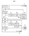
- FIG. 2 is a diagram showing a detailed configuration of the battery device 11, the frame device 12, and the driving device 13 of FIG. 2 shows a state in which the battery device 11 is mounted on the frame device 12 and the respective contacts are electrically connected.
- the battery device 11 includes a battery 21, a switch 22, a low-pass filter 23, a contact 24, a microcomputer 25, a reader / writer 26, and a high-pass filter 27.
- the battery 21 includes one or more battery cells and a control circuit therein, and outputs a DC voltage / DC current, that is, DC power, through a power line.
- the switch 22 is arranged on the power line between the battery 21 and the low-pass filter 23, and performs a switching operation under the control of the microcomputer 25. That is, when the switch 22 is turned on (energized state), the DC power from the battery 21 is supplied to the low-pass filter 23 through the power line. On the other hand, when the switch 22 is in an off state (a power shielding state), DC power is not supplied to the low pass filter 23.
- the low-pass filter 23 is disposed on the power line between the battery 21 and the contact 24, and enables DC power to be supplied to the frame device 12 connected via the contact 24.
- the low-pass filter 23 blocks a high-frequency signal generated by the reader / writer 26 and transmitted through the power line.
- the microcomputer 25 controls the switch 22 and the reader / writer 26.
- the microcomputer 25 has a memory 25A and can store various kinds of information.
- the reader / writer 26 communicates with the frame device 12 connected via the contact 24 under the control of the microcomputer 25.
- the reader / writer 26 is originally for electromagnetically coupling with the IC chip to exchange high frequency signals with the IC chip. That is, the reader / writer 26 is provided for writing and reading information according to the standard of the IC chip.
- a high frequency signal (AC signal) is transmitted / received via the power line. That is, the high-frequency signal originally transmitted / received by the coil or the like in the reader / writer 26 is superimposed on the power line via the high-pass filter 27, and communication with the IC chip is performed via the power line.
- the high-pass filter 27 passes the high-frequency signal generated by the reader / writer 26 and transmits it to the frame device 12 through the power line.
- the high-pass filter 33 cuts off DC power transmitted through the power line.
- the battery device 11 is configured as described above, and supplies DC power to the frame device 12.
- the frame device 12 includes a contact 31, a low-pass filter 32, a high-pass filter 33, and an IC chip 34.
- the low-pass filter 32 is disposed on the power line between the contact 31 and the drive device 13, and enables DC power supplied from the battery device 11 connected via the contact 31 to the drive device 13.
- the low-pass filter 32 blocks a high-frequency signal generated by the reader / writer 26 of the battery device 11 and transmitted through the power line.
- the high-pass filter 33 allows a high-frequency signal generated by the reader / writer 26 of the battery device 11 to pass through and can be transmitted to the IC chip 34 through the power line.
- the high pass filter 33 cuts off DC power supplied through the power line.
- the IC chip 34 performs processing according to a command corresponding to the high-frequency signal transmitted from the reader / writer 26 with the power obtained from the high-frequency signal superimposed on the power line.
- the IC chip 34 performs load modulation on the processing result and transmits the result to the reader / writer 26 via the power line.
- the IC chip 34 is a storage element and has a memory 34A, and can store information and processing results transmitted from the reader / writer 26.
- the IC chip 34 can be configured by an electronic tag such as an IC tag based on various standards. For example, not only standards such as FeliCa, NFC (Near Field Communication), RFID (Radio Frequency Identification), Mifare (both are trademarks), but also electronic tags having a unique configuration not based on these standards can be prepared.
- the IC chip 34 preferably has a function of reading and outputting at least information stored therein by a high-frequency signal, and a function of storing supplied information. Moreover, either a passive type or an active type may be used.
- the frame device 12 is configured as described above, and supplies DC power from the battery device 11 to the drive device 13.
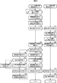
- step S11 When the battery device 11 is mounted on the frame device 12 and the battery device 11 and the frame device 12 are electrically connected (“Yes” in step S11), the authentication connection process is started.
- step S12 the microcomputer 25 generates a command for reading authentication information. Specifically, authentication information for uniquely identifying the frame device 12 is stored in the memory 34A of the IC chip 34 of the frame device 12, and a command for reading this is generated.
- step S13 the reader / writer 26 modulates a high frequency signal as a high frequency signal in response to the command. Specifically, the reader / writer 26 modulates the amplitude of a carrier wave having a frequency of 13.56 MHz as a high-frequency signal in accordance with the command generated in step S12. In step S14, the reader / writer 26 outputs a high-frequency signal through the power line.
- the high-frequency signal output from the battery device 11 is transmitted to the frame device 12 through the power line.
- the IC chip 34 receives the high-frequency signal transmitted through the power line (step S31).
- step S32 the IC chip 34 uses the power obtained from the high-frequency signal to execute an authentication information read command, and reads the authentication information of the frame device 12 stored in the memory 34A (step S33).
- step S34 the IC chip 34 performs load modulation corresponding to the read authentication information.
- the signal of the reflected wave generated by the load modulation of the high frequency signal is received by the battery device 11 through the power line. Then, in the battery device 11, the reader / writer 26 demodulates the reflected wave signal generated by the load modulation (step S15). As a result, the authentication information is read from the frame device 12.
- step S16 the microcomputer 25 determines whether or not the connection with the frame device 12 is the first connection. For example, when the authentication information of the frame device 12 is not stored in the memory 25A, when it is determined in step S16 that the connection is the first time, the process proceeds to step S17.
- step S17 the microcomputer 25 stores the authentication information read from the frame device 12 in the memory 25A. Thereby, the battery apparatus 11 has memorize
- step S18 the microcomputer 25 reads out authentication information for uniquely identifying the battery device 11 stored in the memory 25A.
- step S19 the reader / writer 26 modulates the high-frequency signal in accordance with the read authentication information, and outputs the high-frequency signal via the power line (step S20).
- the high-frequency signal output from the battery device 11 is transmitted to the frame device 12 through the power line.
- the IC chip 34 receives the high-frequency signal transmitted through the power line (step S35), and stores the authentication information obtained from the high-frequency signal in the memory 34A (step S36). That is, the authentication information of the connection destination device is held not only on the battery device 11 side but also on the frame device 12 side.
- the DC power from the battery 21 is supplied to the frame device 12 via the power line, and the drive device 13 is thereby driven.
- step S16 determines whether the connection is not the first time, that is, the second or later connection. If it is determined in step S16 that the connection is not the first time, that is, the second or later connection, the process proceeds to step S21.
- step S21 the microcomputer 25 compares the authentication information read from the frame device 12 with the authentication information stored in the memory 25A by the first connection, and performs an authentication process.
- step S22 the microcomputer 25 determines whether or not the authentication information read from the frame device 12 is valid authentication information, based on the collation result in step S21. If it is determined in step S22 that the authentication information is valid, the process proceeds to step S23.
- step S23 the microcomputer 25 controls the switch 22 to process valid authentication information.
- a process of valid authentication information for example, when the switch 22 is turned on, the battery 21 is controlled, and direct-current power from the battery 21 is supplied to the frame device 12 via the power line. Is driven.
- step S24 the microcomputer 25 stores the result of the authentication process in the memory 25A.
- step S26 the reader / writer 26 modulates the high-frequency signal according to the result of the authentication process, and outputs the high-frequency signal via the power line (step S20).
- the result of the authentication process is stored in the memory 34A of the IC chip 34.
- step S22 determines whether the authentication information is invalid. If it is determined in step S22 that the authentication information is invalid, the process proceeds to step S25.
- step S25 the microcomputer 25 controls the switch 22 to process invalid authentication information.
- the unauthorized authentication information is processed by turning off the switch 22 so that the battery 21 is controlled and the DC power from the battery 21 is not supplied to the frame device 12, thereby driving the drive device 13. I can't do that.
- the drive device 13 can be driven only by the battery device 11 and the frame device 12 of the correct combination.
- the authentication connection process when the battery device 11 is connected to the frame device 12 for the first time, the authentication information read from the frame device 12 is stored.
- the second and subsequent connections with the frame device 12 are made, authentication processing based on the authentication information read from the frame device 12 and the authentication information stored in the first connection is performed.
- the battery 21 is controlled in accordance with the result of the authentication process.
- the battery device 11 stores the authentication information of the frame device 12 mounted at the start of use, and does not supply power other than the frame device 12 holding the authentication information.
- the battery device 11 cannot be used with any other frame device other than the frame device 12 that is initially mounted, and thus provides a more secure anti-theft function. can do.
- a theft prevention measure using a conventional physical key may be added to the theft prevention function.
- Second Embodiment> By the way, as described above, the battery device 11 is premised on being charged for every use from, for example, one day to about one week. Therefore, the battery device 11 is detached from the frame device 12 according to the use frequency of the electric assist bicycle 1. It is necessary to charge. Then, next, the battery charge system which charges the battery device 11 is demonstrated.
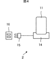
- FIG. 4 is a diagram illustrating a configuration example of the battery charging system.
- the battery charging system 2 includes a battery device 11 and a charging device 14 that charges the battery device 11.
- the AC plug 15 of the charging device 14 is connected to the household outlet 16, whereby the charging device 14 can use the AC power source via the AC plug 15.
- the charging device 14 has a shape in which the battery device 11 can be placed, and a power supply terminal (contact 43 in FIG. 5) is provided at a position corresponding to the power supply terminal (contact 24 in FIG. 5) of the battery device 11.
- the battery device 11 to be placed can be electrically connected.
- the charging device 14 generates DC power for charging the battery device 11 from the AC power supplied from the AC plug 15 and supplies the direct current power to the mounted battery device 11. Thereby, the battery device 11 is charged.
- the battery charging system 2 is configured as described above.
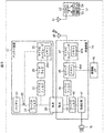
- FIG. 5 is a diagram showing a detailed configuration of the battery device 11 and the charging device 14 of FIG.
- the battery device 11 is placed on the charging device 14 and the respective contacts are electrically connected.
- the battery device 11 has the same configuration as the battery device 11 of FIG.
- FIG. 5 shows a management server 17 that manages information related to the authentication history and usage history of the battery device 11 (hereinafter referred to as history information).
- the charging device 14 includes a charging circuit 41, a low-pass filter 42, a contact 43, a high-pass filter 44, an IC chip 45, a non-contact I / F 46, a microcomputer 47, and a communication circuit 48.
- the charging circuit 41 generates DC power for charging the battery device 11 from the AC power supplied from the AC plug 15, and supplies the DC power to the battery device 11 via the power line.
- the low-pass filter 42 is arranged on the power line between the charging circuit 41 and the contact 43 and enables the DC power from the charging circuit 41 to be supplied to the battery 21 of the battery device 11 connected via the contact 43.
- the low-pass filter 42 blocks a high-frequency signal generated by the reader / writer 26 of the battery device 11 and transmitted via the power line.
- the high-pass filter 44 passes the high-frequency signal generated by the reader / writer 26 of the battery device 11 and transmits it to the IC chip 45 through the power line.
- the high pass filter 44 cuts off DC power supplied through the power line.
- the IC chip 45 performs processing according to a command corresponding to the high-frequency signal transmitted from the reader / writer 26 with the power obtained from the high-frequency signal superimposed on the power line.
- the IC chip 45 performs load modulation on the processing result and transmits the result to the reader / writer 26 via the power line.
- the IC chip 45 is a storage element and has a memory 45A, and can store information transmitted from the reader / writer 26 and a processing result. Further, the IC chip 45 has a non-contact I / F 46 corresponding to a standard such as FeliCa (trademark), and by performing proximity communication with an electronic device in which the IC chip corresponding to the standard is incorporated, The information stored in the memory 45A can be transmitted.
- a standard such as FeliCa (trademark)
- the microcomputer 47 controls the IC chip 45 and the communication circuit 48.
- the microcomputer 47 has a memory 47A, and can store various information.
- the communication circuit 48 communicates with the management server 17 via a predetermined network under the control of the microcomputer 47.
- the charging device 14 is configured as described above, and supplies DC power for charging to the battery device 11.
- the management server 17 includes a communication circuit 51, a CPU 52, a storage device 53, and a display 54.
- the communication circuit 51 communicates with the charging device 14 via a predetermined network according to the control of the CPU 52.
- the CPU 52 controls the operation of each part of the management server 17.
- the CPU 52 stores information supplied from the communication circuit 51 in the storage device 53. Further, the CPU 52 displays information from the communication circuit 51 or the storage device 53 on the display 54.
- the management server 17 is configured as described above, and manages history information transmitted from the charging device 14.
- the communication performed between the charging device 14 and the management server 17 via the network is not only wireless communication and wired communication, but also communication in which wireless communication and wired communication are mixed, that is, wireless communication is performed in a certain section. In other sections, wired communication may be performed.
- step S51 the authentication charging process is started.
- steps S52 to S54 as in steps S12 to S14 in FIG. 3, the microcomputer 25 generates an authentication information reading command, and the reader / writer 26 transmits a high-frequency signal corresponding to the authentication information reading command to the power line. Is output via.
- the high frequency signal output from the battery device 11 is transmitted to the charging device 14 through the power line.
- steps S71 to S74 as in steps S31 to S34 of FIG. 3, the IC chip 45 receives a high-frequency signal, and a command for reading authentication information obtained from the received high-frequency signal is executed and stored in the memory 45A. The authentication information of the charged charging device 14 is read out. Then, load modulation according to the authentication information is performed by the IC chip 45 and transmitted to the battery device 11 through the power line.
- the reflected wave signal generated by load modulation of the high-frequency signal is received and demodulated by the battery device 11 via the power line (step S55).
- the authentication information is read from the charging device 14.
- Steps S55 to S65 as in Steps S15 to S25 of FIG. 3, when the first connection with the charging device 14 is performed, the microcomputer 25 reads the data from the charging device 14. Authentication information is stored in the memory 25A. Thereby, the battery apparatus 11 memorize
- the battery device 11 can be used not only with the correct combination of the frame devices 12 but also with the correct combination of the charging devices 14.
- step S60 a high-frequency signal corresponding to the authentication information is output as in step S20 of FIG.
- steps S75 and S76 a high-frequency signal is received in the same manner as in steps S35 and S36 in FIG. 3, and authentication information obtained thereby is stored in memory 45A.
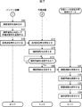
- step S66 of FIG. 7 the microcomputer 25 of the battery device 11 reads the history information stored in the memory 25A.
- this history information in addition to the authentication history and usage history of the battery device 11, for example, information that can be accumulated on the battery device 11 side, such as usage status and self-diagnosis information of the electric assist bicycle 1 acquired by the frame device 12. Is included.
- step S67 the reader / writer 26 modulates the high-frequency signal in response to the history information and outputs it via the power line (step S68).
- the high frequency signal output from the battery device 11 is transmitted to the charging device 14 through the power line.
- the IC chip 45 receives the high frequency signal (step S77), and the history information obtained thereby is stored in the memory 45A (step S78).
- step S79 the microcomputer 47 determines whether or not to transmit history information to the management server 17. For example, when transmission of management information is instructed by a user operation, it is determined to transmit history information (“Yes” in step S79), and the process proceeds to step S80.
- step S80 the communication circuit 48 transmits history information to the management server 17 according to the control of the microcomputer 47.
- step S91 When the history information is transmitted from the charging device 14, the history information is received by the communication circuit 51 in the management server 17 (step S91).
- step S ⁇ b> 92 the CPU 51 stores the received history information in the storage device 53. For example, when analysis of history information is instructed by a user operation, the CPU 51 performs a predetermined analysis process on the history information in step S93, and displays the analysis result on the display 54 in step S94. .
- history information such as authentication information of the frame device 12 on which the battery device 11 is mounted, a result of the authentication process, usage history, and the like are collectively managed by the management server 17 and analyzed. It is possible to take further antitheft measures by effectively utilizing.
- the authentication process when the battery device 11 is connected to the charging device 14 for the first time, the authentication information read from the charging device 14 is stored.
- the second or subsequent connection with the charging device 14 an authentication process based on the authentication information read from the charging device 14 and the authentication information stored in the first connection is performed.
- the battery 21 is controlled in accordance with the result of the authentication process.
- the battery device 11 stores the authentication information of the charging device 14 placed at the time of the first charging after the start of use, and does not charge with power other than the charging device 14 that holds the authentication information. become.
- the battery device 11 cannot be used with any other charging device other than the charging device 14 that is initially placed. Unless it can be charged, once it is discharged, the battery device 11 cannot be used again.
- the charging device 14 is installed at a place away from the electrically assisted bicycle 1 such as the user's home, it is very unlikely that the battery device 11 and the charging device 14 will be stolen at the same time. Can provide.
- the IC chip 34 of the frame device 12 is operated by a high-frequency signal from the reader / writer 26 of the battery device 11, the IC chip 34 and peripheral circuits do not need a power supply during the authentication process. That is, it is not necessary to separately install a power source for authentication processing on the frame device 12 side, and authentication processing can be performed at a stage where the battery device 11 is not energized. Further, by encrypting communication between the reader / writer 26 of the battery device 11 and the IC chip 34 of the frame device 12, unauthorized use due to impersonation of a legitimate frame device can be prevented. This makes it possible to realize a secure authentication system with a simpler mechanism than before.
- the battery device 11 is a consumable item, and considering the possibility of using a plurality of battery devices in parallel, on the battery device 11 side, the frame device 12 on which the battery device 11 is to be mounted or the battery device 11 is mounted. It is considered that a method of storing authentication information of the charging device 14 and performing an authentication process is a desirable method for operation.
- the battery device 11 is a consumable item, for example, replacement every year is necessary.
- the battery device 11 holds the authentication information, the new battery device 11 that does not yet hold the authentication information Without setting, it can be immediately mounted on the frame device 12 or charged by the charging device 14.
- the frame device 12 of the electrically assisted bicycle 1 and the charging device 14 that charges the battery device 11 are described as electronic devices on which the battery device 11 is mounted. It may be connected to a device via a power line and the above-described authentication process may be performed.
- the battery device may be mounted on an electric vehicle such as an electric automobile, an electric motorcycle, or an electric wheelchair.
- the battery device 11 holds the authentication information of one frame device 12.
- the battery device 11 can hold the authentication information of a plurality of frame devices 12. Setting may be made so that a plurality of frame devices 12 can hold common authentication information.
- a plurality of battery devices 11 can be shared by a plurality of frame devices 12, so that even when a specific business operator operates a plurality of electric assist bicycles 1, such as a bicycle rental, for example.
- the electrically assisted bicycle 1 owned by the company it is possible to easily construct a mechanism in which the battery device 11 can be shared and the battery device 11 cannot be used in other electrically assisted bicycles.
- a system represents the whole apparatus comprised by a some apparatus.
- the present technology can be configured as follows.
- the read authentication information is stored, and a control unit that controls the battery includes:
- the control unit performs an authentication process of the electronic device based on the read authentication information and the authentication information stored in the first connection.
- the electronic device is a power supply device that supplies DC power to a driving device that generates the power driving force in an electrically assisted bicycle that travels forward by generating auxiliary power driving force in addition to human power driving force.
- the battery device according to [1] wherein the control unit controls DC power output from the battery to the power supply device via the power line.
- the power supply device is provided with a storage element that outputs the stored authentication information to the battery device via the power line by load-modulating a high-frequency signal input via the power line.
- the electronic device is a charging device for charging the battery, The battery device according to [1], wherein the control unit controls DC power output from the charging device to the battery via the power line.
- the charging device is provided with a storage element that outputs the stored authentication information to the battery device via the power line by load-modulating a high-frequency signal input via the power line.
- a storage element that outputs the stored authentication information to the battery device via the power line by load-modulating a high-frequency signal input via the power line.
- a method for controlling a battery device including a battery, When the electronic device is connected to the battery via the power line, the authentication information of the electronic device is read out by communicating by outputting a high-frequency signal via the power line, When the first connection with the electronic device is made, the read authentication information is stored and the battery is controlled, When the second or subsequent connection with the electronic device is performed, the electronic device performs authentication processing based on the read authentication information and the authentication information stored in the first connection, and the electronic device A control method for controlling the battery according to a result of the authentication process.
- a battery that outputs DC power via a power line;
- a power supply device that supplies DC power to a drive device that generates auxiliary power drive force in addition to human power drive force;
- a communication unit that reads out authentication information of the power supply device by outputting and communicating a high-frequency signal via the power line;
- the control unit that controls the battery includes:
- the control unit authenticates the power supply device based on the read authentication information and the authentication information stored in the first connection.
- 1 electric assist bicycle 2 battery charging system, 11 battery device, 12 frame device, 13 drive device, 14 charging device, 17 management server, 21 battery, 22 switch, 24 contacts, 25 microcomputer, 25A memory, 26 reader / writer, 31 contacts, 34 IC chips, 34A memory, 43 contacts, 45 IC chips, 45A memory
Abstract
本技術は、安全性の高い盗難防止機能を提供することができるようにするバッテリ装置、制御方法、及び電動車両に関する。 バッテリは、電力線を介して直流電力を出力し、リーダライタは、電子機器が電力線を介してバッテリと接続された場合、電力線を介して高周波信号を出力して通信することで、電子機器の認証情報を読み出し、マイクロコンピュータは、電子機器との1回目の接続が行われた場合、読み出された認証情報を記憶するとともに、バッテリを制御し、電子機器との2回目以降の接続が行われた場合、読み出された認証情報及び1回目の接続で記憶された認証情報に基づいた電子機器の認証処理を行い、電子機器の認証処理の結果に応じてバッテリを制御する。本技術は、例えば、電動アシスト自転車に搭載されるバッテリ装置に適用することができる。
Description
本技術は、バッテリ装置、制御方法、及び電動車両に関し、特に、安全性の高い盗難防止機能を提供することができるようにしたバッテリ装置、制御方法、及び電動車両に関する。
近年、電動アシスト自転車が普及している(例えば、特許文献1参照)。
電動アシスト自転車に搭載されるバッテリ装置は、1日から1週間程度の利用ごとに充電されることを前提としており、その便宜のために自転車本体と脱着・運搬が簡便に行えるように設計されている。そのため、バッテリ装置のみ盗難に遭いやすいという一面がある。
バッテリ装置の盗難防止策としては、自転車から離れるときに、自転車からバッテリ装置を取り外すのが最も確実な方法であるが、外出先などでは、取り外したバッテリ装置を持ち運ばねばならず、現実的な方法であるとは言えない。
従来の技術では、自転車本体と同一の鍵によりバッテリ装置にも施錠できるように対策が施されているが、物理的な鍵であるため、工具により鍵穴を破壊するなどの強引な手口による盗難を防ぎきれていないのが現状である。そのため、より有効な盗難防止策が求められていた。
本技術はこのような状況に鑑みてなされたものであり、安全性の高い盗難防止機能を提供することができるようにするものである。
本技術の一側面のバッテリ装置は、電力線を介して直流電力を出力するバッテリと、電子機器が前記電力線を介して前記バッテリと接続された場合、前記電力線を介して高周波信号を出力して通信することで、前記電子機器の認証情報を読み出す通信部と、前記電子機器との1回目の接続が行われた場合、読み出された前記認証情報を記憶するとともに、前記バッテリを制御する制御部とを備え、前記制御部は、前記電子機器との2回目以降の接続が行われた場合、読み出された前記認証情報及び1回目の接続で記憶された前記認証情報に基づいた前記電子機器の認証処理を行い、前記電子機器の認証処理の結果に応じて前記バッテリを制御する。
前記電子機器は、人力駆動力に加えて補助的な電力駆動力を発生させて前方方向へ走行する電動アシスト自転車において、前記電力駆動力を発生させる駆動装置に直流電力を供給する電力供給装置であり、前記制御部は、前記バッテリから前記電力線を介して前記電力供給装置に出力される直流電力を制御する。
前記電力供給装置には、前記電力線を介して入力される高周波信号を負荷変調することにより、記憶している前記認証情報を前記電力線を介して前記バッテリ装置に出力する記憶素子が設けられる。
前記電子機器は、前記バッテリの充電を行うための充電装置であり、前記制御部は、前記充電装置から前記電力線を介して前記バッテリに出力される直流電力を制御する。
前記充電装置には、前記電力線を介して入力される高周波信号を負荷変調することにより、記憶している前記認証情報を前記電力線を介して前記バッテリ装置に出力する記憶素子が設けられる。
前記バッテリ装置の認証履歴及び利用履歴に関する履歴情報を記憶する記憶部をさらに備え、前記通信部は、前記電力線を介して高周波信号を出力して通信することで、記憶された前記履歴情報を前記充電装置に送信する。
バッテリ装置は、独立した装置であってもよいし、1つの装置を構成している内部ブロックであってもよい。
本技術の一側面の制御方法又は電動車両は、前述した本技術の一側面のバッテリ装置に対応する制御方法又は電動車両である。
本技術の一側面のバッテリ装置、制御方法、及び電動車両においては、電子機器が電力線を介してバッテリと接続された場合、電力線を介して高周波信号を出力して通信することで、電子機器の認証情報が読み出され、電子機器との1回目の接続が行われた場合、読み出された認証情報が記憶されるとともに、バッテリが制御され、電子機器との2回目以降の接続が行われた場合、読み出された認証情報及び1回目の接続で記憶された認証情報に基づいた電子機器の認証処理が行われ、電子機器の認証処理の結果に応じてバッテリが制御される。
本技術の一側面によれば、安全性の高い盗難防止機能を提供することができる。
以下、図面を参照しながら本技術の実施の形態について説明する。
<1.第1の実施の形態>
[電動アシスト自転車の構成例]
図1は、電動アシスト自転車の構成例を示す図である。
[電動アシスト自転車の構成例]
図1は、電動アシスト自転車の構成例を示す図である。
電動アシスト自転車1は、人力駆動力に加えて補助的な電力駆動力を発生させて前方方向へ走行する自転車である。
図1に示すように、電動アシスト自転車1の主要な骨格部分は、金属管製の車体フレームから構成されており、このフレームには、前輪、後輪、ハンドル、サドル、ペダルなどが取り付けられている。また、フレームには、バッテリ装置11からの電力を駆動装置13に供給するためのフレーム装置12が設けられており、ペダルに与えられた踏力が制御回路(不図示)などを介して駆動装置13に伝達されることで、後輪が回転される。その結果、電動アシスト自転車1を前方方向に走らせることが可能となる。
なお、フレーム装置12は、バッテリ装置11を搭載可能な形状を有するとともに、バッテリ装置11の電源端子(図2の接点24)に対応する位置に電源端子(図2の接点31)が設けられており、搭載されるバッテリ装置11と電気的に接続可能とされる。そのため、フレーム装置12に着脱可能に搭載されるバッテリ装置11は、例えば、充電時には取り外すことが可能とされる。
電動アシスト自転車1は、以上のように構成される。
[各装置の詳細な構成例]
図2は、図1のバッテリ装置11、フレーム装置12、及び駆動装置13の詳細な構成を示す図である。なお、図2においては、バッテリ装置11がフレーム装置12に搭載され、それぞれの接点が電気的に接続された状態を図示している。
図2は、図1のバッテリ装置11、フレーム装置12、及び駆動装置13の詳細な構成を示す図である。なお、図2においては、バッテリ装置11がフレーム装置12に搭載され、それぞれの接点が電気的に接続された状態を図示している。
図2に示すように、バッテリ装置11は、バッテリ21、スイッチ22、ローパスフィルタ23、接点24、マイクロコンピュータ25、リーダライタ26、及びハイパスフィルタ27から構成される。
バッテリ21は、内部に1個以上のバッテリセル及び制御用の回路を内蔵し、電力線を介して直流電圧・直流電流、すなわち直流電力を出力する。
スイッチ22は、バッテリ21とローパスフィルタ23との間の電力線上に配置され、マイクロコンピュータ25の制御に従い、スイッチング動作する。すなわち、スイッチ22がオン状態(通電状態)となったとき、バッテリ21からの直流電力は、電力線を介してローパスフィルタ23に供給される。一方、スイッチ22がオフ状態(遮電状態)となったとき、ローパスフィルタ23には直流電力が供給されないことになる。
ローパスフィルタ23は、バッテリ21と接点24との間の電力線上に配置され、接点24を介して接続されるフレーム装置12に直流電力を供給可能にする。また、ローパスフィルタ23は、リーダライタ26が発生し、電力線を介して伝達される高周波信号を遮断する。
マイクロコンピュータ25は、スイッチ22及びリーダライタ26を制御する。また、マイクロコンピュータ25は、メモリ25Aを有しており、各種の情報を記憶することができる。
リーダライタ26は、マイクロコンピュータ25の制御に従い、接点24を介して接続されるフレーム装置12と通信を行う。
具体的には、リーダライタ26は、本来、ICチップと電磁結合して、ICチップとの間で高周波信号を授受するためのものである。すなわち、リーダライタ26は、ICチップの規格に対応して情報を書き込み、読み出すために設けられるものである。しかし、本実施の形態においては、電力線を介して高周波信号(交流信号)が授受される。すなわち、本来、リーダライタ26内のコイル等により授受していた高周波信号は、ハイパスフィルタ27を介して電力線に重畳され、ICチップとの通信は電力線を経由して行われる。
ハイパスフィルタ27は、リーダライタ26が発生する高周波信号を通過して、電力線を介してフレーム装置12に伝達させる。また、ハイパスフィルタ33は、電力線を介して伝達される直流電力を遮断する。
バッテリ装置11は、以上のように構成され、直流電力を、フレーム装置12に供給する。
図2に示すように、フレーム装置12は、接点31、ローパスフィルタ32、ハイパスフィルタ33、及びICチップ34から構成される。
ローパスフィルタ32は、接点31と駆動装置13との間の電力線上に配置され、接点31を介して接続されるバッテリ装置11から供給される直流電力を、駆動装置13に供給可能にする。また、ローパスフィルタ32は、バッテリ装置11のリーダライタ26が発生し、電力線を介して伝達される高周波信号を遮断する。
ハイパスフィルタ33は、バッテリ装置11のリーダライタ26が発生する高周波信号を通過して、電力線を介してICチップ34に伝達可能にする。また、ハイパスフィルタ33は、電力線を介して供給される直流電力を遮断する。
ICチップ34は、電力線に重畳された高周波信号により得られる電力により、リーダライタ26から送信された高周波信号に対応するコマンドに応じた処理を行う。ICチップ34は、処理結果を負荷変調することで、電力線を介してリーダライタ26に伝達する。
また、ICチップ34は、記憶素子であって、メモリ34Aを有しており、リーダライタ26から送信される情報や処理結果を記憶することができる。
なお、ICチップ34は、各種の規格に基づくICタグなどの電子タグにより構成することができる。例えばFeliCa,NFC(Near Field Communication),RFID(Radio Frequency Identification),Mifare(いずれも商標)等の規格は勿論、これらの規格に基づかない独自の構成の電子タグを用意することもできる。ICチップ34は、高周波信号により、少なくとも内部に記憶する情報を読み出し出力する機能を有し、さらに供給された情報を記憶する機能を有するのが好ましい。また、パッシブタイプとアクティブタイプのいずれでもよい。
フレーム装置12は、以上のように構成され、バッテリ装置11からの直流電力を、駆動装置13に供給する。
[認証接続処理の流れ]
次に、図3のフローチャートを参照して、バッテリ装置11とフレーム装置12との間で行われる認証接続処理について説明する。
次に、図3のフローチャートを参照して、バッテリ装置11とフレーム装置12との間で行われる認証接続処理について説明する。
バッテリ装置11がフレーム装置12に搭載され、バッテリ装置11とフレーム装置12が電気的に接続されると(ステップS11の「Yes」)、認証接続処理が開始される。
ステップS12において、マイクロコンピュータ25は、認証情報読み取りのコマンドを生成する。具体的には、フレーム装置12のICチップ34のメモリ34Aには、フレーム装置12を一意に識別するための認証情報が記憶されており、これを読み出すコマンドが生成される。
ステップS13において、リーダライタ26は、コマンドに対応して、高周波信号としての高周波信号を変調する。具体的には、リーダライタ26は、高周波信号としての13.56MHzの周波数の搬送波を、ステップS12で生成されたコマンドに対応して振幅変調する。ステップS14において、リーダライタ26は、電力線を介して高周波信号を出力する。
バッテリ装置11から出力された高周波信号は、電力線を介してフレーム装置12に伝達される。そして、フレーム装置12において、ICチップ34は、電力線を介して伝達される高周波信号を受信する(ステップS31)。
ステップS32において、ICチップ34は、高周波信号から得られた電力を用いて、認証情報読み取りのコマンドを実行し、メモリ34Aに記憶されたフレーム装置12の認証情報を読み出す(ステップS33)。そして、ステップS34において、ICチップ34は、読み出された認証情報に対応して負荷変調を行う。
ICチップ34において、高周波信号の負荷変調により発生する反射波の信号は、電力線を介してバッテリ装置11により受信される。そして、バッテリ装置11において、リーダライタ26は、負荷変調により発生する反射波の信号を復調する(ステップS15)。これにより、フレーム装置12から認証情報が読み出されたことになる。
ステップS16において、マイクロコンピュータ25は、フレーム装置12との接続が1回目の接続であるか否かを判定する。例えばメモリ25Aにフレーム装置12の認証情報が記憶されていない場合など、ステップS16において、1回目の接続であると判定された場合、処理は、ステップS17に進む。
ステップS17において、マイクロコンピュータ25は、フレーム装置12から読み出された認証情報を、メモリ25Aに記憶する。これにより、バッテリ装置11は、自身が搭載されるべきフレーム装置12の認証情報を記憶したことになる。
ステップS18において、マイクロコンピュータ25は、メモリ25Aに記憶されたバッテリ装置11を一意に識別するための認証情報を読み出す。ステップS19において、リーダライタ26は、読み出された認証情報に対応して高周波信号を変調し、その高周波信号を電力線を介して出力する(ステップS20)。
バッテリ装置11から出力された高周波信号は、電力線を介してフレーム装置12に伝達される。そして、フレーム装置12において、ICチップ34は、電力線を介して伝達される高周波信号を受信して(ステップS35)、高周波信号から得られる認証情報をメモリ34Aに記憶する(ステップS36)。すなわち、バッテリ装置11側だけでなく、フレーム装置12側でも、接続先の装置の認証情報が保持される。
そして、1回目の接続では、バッテリ21からの直流電力が電力線を介してフレーム装置12に供給され、それにより駆動装置13が駆動される。
一方、ステップS16において、1回目の接続でない、すなわち、2回目以降の接続であると判定された場合、処理は、ステップS21に進む。ステップS21において、マイクロコンピュータ25は、フレーム装置12から読み出された認証情報と、1回目の接続でメモリ25Aに記憶された認証情報を照合して、認証処理を行う。
ステップS22において、マイクロコンピュータ25は、ステップS21の照合の結果に基づいて、フレーム装置12から読み出された認証情報が正当な認証情報であるか否かを判定する。ステップS22において、正当な認証情報であると判定された場合、処理は、ステップS23に進む。
ステップS23において、マイクロコンピュータ25は、スイッチ22を制御して、正当な認証情報の処理を行う。正当な認証情報の処理としては、例えば、スイッチ22をオン状態にすることで、バッテリ21が制御され、バッテリ21からの直流電力が電力線を介してフレーム装置12に供給され、それにより駆動装置13が駆動される。
ステップS24において、マイクロコンピュータ25は、認証処理の結果をメモリ25Aに記憶する。また、ステップS26において、リーダライタ26は、認証処理の結果に対応して高周波信号を変調し、その高周波信号を電力線を介して出力する(ステップS20)。これにより、フレーム装置12においては、ICチップ34のメモリ34Aに認証処理の結果が記憶される。
一方、ステップS22において、不当な認証情報であると判定された場合、処理は、ステップS25に進む。
ステップS25において、マイクロコンピュータ25は、スイッチ22を制御して、不当な認証情報の処理を行う。不当な認証情報の処理としては、例えば、スイッチ22をオフ状態にすることで、バッテリ21が制御され、バッテリ21からの直流電力がフレーム装置12に供給されず、それにより駆動装置13を駆動させることができなくなる。すなわち、正しい組み合わせのバッテリ装置11とフレーム装置12でしか、駆動装置13が駆動されないことになる。
そして、不当な認証情報の場合においても、ステップS24,S26,S20の処理が行われ、前述した正当な認証情報の場合と同様に、認証処理の結果に対応した高周波信号が出力され、認証処理の結果がICチップ34のメモリ34Aに記憶される。これにより、メモリ34Aには、バッテリ装置11の認証情報や認証処理の結果が記憶されることになるので、例えば、次回、バッテリ装置11と接続されたとき、それらの情報を認証処理などで用いるようにしてもよい。
以上のように、認証接続処理においては、バッテリ装置11によって、フレーム装置12との1回目の接続が行われた場合、フレーム装置12から読み出された認証情報が記憶される。そして、フレーム装置12との2回目以降の接続が行われた場合には、フレーム装置12から読み出された認証情報と、1回目の接続で記憶された認証情報に基づいた認証処理が行われ、認証処理の結果に応じてバッテリ21の制御が行われる。
すなわち、バッテリ装置11は、使用開始時に搭載されたフレーム装置12の認証情報を記憶して、その認証情報を保持しているフレーム装置12以外には電力を供給しないことになる。これにより、例えばバッテリ装置11が盗難に遭った場合でも、バッテリ装置11は、最初に搭載されたフレーム装置12以外の他のフレーム装置では使用できなくなるので、より安全性の高い盗難防止機能を提供することができる。また、この盗難防止機能に、従来の物理的な鍵による盗難防止策を加えてもよい。
<2.第2の実施の形態>
ところで、前述したように、バッテリ装置11は、例えば1日から1週間程度の利用ごとに充電されることを前提としているため、電動アシスト自転車1の利用頻度に応じて、フレーム装置12から取り外して充電を行う必要がある。そこで、次に、バッテリ装置11の充電を行うバッテリ充電システムについて説明する。
ところで、前述したように、バッテリ装置11は、例えば1日から1週間程度の利用ごとに充電されることを前提としているため、電動アシスト自転車1の利用頻度に応じて、フレーム装置12から取り外して充電を行う必要がある。そこで、次に、バッテリ装置11の充電を行うバッテリ充電システムについて説明する。
[バッテリ充電システムの構成例]
図4は、バッテリ充電システムの構成例を示す図である。
図4は、バッテリ充電システムの構成例を示す図である。
図4に示すように、バッテリ充電システム2は、バッテリ装置11と、バッテリ装置11の充電を行う充電装置14から構成される。
家庭用のコンセント16には、充電装置14のACプラグ15が接続され、これにより、充電装置14は、ACプラグ15を介してAC電源を利用可能とされる。充電装置14は、バッテリ装置11を載置可能な形状を有するとともに、バッテリ装置11の電源端子(図5の接点24)に対応する位置に電源端子(図5の接点43)が設けられており、載置されるバッテリ装置11と電気的に接続可能とされる。
充電装置14は、ACプラグ15から供給されるAC電力からバッテリ装置11を充電するための直流電力を生成し、載置されたバッテリ装置11に供給する。これにより、バッテリ装置11への充電が行われる。
バッテリ充電システム2は、以上のように構成される。
[各装置の詳細な構成例]
図5は、図4のバッテリ装置11及び充電装置14の詳細な構成を示す図である。なお、図5においては、バッテリ装置11が充電装置14に載置され、それぞれの接点が電気的に接続された状態を図示している。
図5は、図4のバッテリ装置11及び充電装置14の詳細な構成を示す図である。なお、図5においては、バッテリ装置11が充電装置14に載置され、それぞれの接点が電気的に接続された状態を図示している。
図5において、バッテリ装置11は、図2のバッテリ装置11と同様の構成を有しているため、その説明は省略する。また、図5には、バッテリ装置11の認証履歴及び利用履歴に関する情報(以下、履歴情報という)の管理を行う管理サーバ17が図示されている。
図5に示すように、充電装置14は、充電回路41、ローパスフィルタ42、接点43、ハイパスフィルタ44、ICチップ45、非接触I/F46、マイクロコンピュータ47、及び通信回路48から構成される。
充電回路41は、ACプラグ15から供給されるAC電力からバッテリ装置11を充電するための直流電力を生成し、電力線を介して、バッテリ装置11に供給する。
ローパスフィルタ42は、充電回路41と接点43との間の電力線上に配置され、接点43を介して接続されるバッテリ装置11のバッテリ21に、充電回路41からの直流電力を供給可能にする。また、ローパスフィルタ42は、バッテリ装置11のリーダライタ26が発生し、電力線を介して伝達される高周波信号を遮断する。
ハイパスフィルタ44は、バッテリ装置11のリーダライタ26が発生する高周波信号を通過して、電力線を介してICチップ45に伝達させる。また、ハイパスフィルタ44は、電力線を介して供給される直流電力を遮断する。
ICチップ45は、電力線に重畳された高周波信号により得られる電力により、リーダライタ26から送信された高周波信号に対応するコマンドに応じた処理を行う。ICチップ45は、処理結果を負荷変調することで、電力線を介してリーダライタ26に伝達する。
また、ICチップ45は、記憶素子であって、メモリ45Aを有しており、リーダライタ26から送信される情報や処理結果を記憶することができる。また、ICチップ45は、FeliCa(商標)等の規格に対応した非接触I/F46を有しており、それらの規格に対応したICチップが内蔵された電子機器と近接通信を行うことで、メモリ45Aに記憶された情報を送信することが可能とされる。
マイクロコンピュータ47は、ICチップ45及び通信回路48を制御する。また、マイクロコンピュータ47は、メモリ47Aを有しており、各種の情報を記憶することができる。
通信回路48は、マイクロコンピュータ47の制御に従い、所定のネットワークを介して、管理サーバ17と通信を行う。
充電装置14は、以上のように構成され、充電を行うための直流電力を、バッテリ装置11に供給する。
図5に示すように、管理サーバ17は、通信回路51、CPU52、記憶装置53、及びディスプレイ54から構成される。
通信回路51は、CPU52の制御に従い、所定のネットワークを介して、充電装置14と通信を行う。
CPU52は、管理サーバ17の各部の動作を制御する。CPU52は、通信回路51から供給される情報を記憶装置53に記憶する。また、CPU52は、通信回路51又は記憶装置53からの情報を、ディスプレイ54に表示する。
管理サーバ17は、以上のように構成され、充電装置14から送信される履歴情報を管理する。
なお、充電装置14と管理サーバ17との間でネットワークを介して行われる通信は、無線通信及び有線通信は勿論、無線通信と有線通信とが混在した通信、すなわち、ある区間では無線通信が行われ、他の区間では有線通信が行われるようなものであってもよい。
[認証充電処理の流れ]
次に、図6及び図7のフローチャートを参照して、バッテリ装置11、充電装置14、及び管理サーバ17により行われる認証充電処理について説明する。
次に、図6及び図7のフローチャートを参照して、バッテリ装置11、充電装置14、及び管理サーバ17により行われる認証充電処理について説明する。
バッテリ装置11が充電装置14に載置され、バッテリ装置11と充電装置14が電気的に接続されると(ステップS51の「Yes」)、認証充電処理が開始される。
ステップS52乃至S54においては、図3のステップS12乃至S14と同様に、マイクロコンピュータ25によって、認証情報読み取りのコマンドが生成され、リーダライタ26によって、認証情報読み取りのコマンドに対応した高周波信号が電力線を介して出力される。
バッテリ装置11から出力された高周波信号は、電力線を介して充電装置14に伝達される。ステップS71乃至S74においては、図3のステップS31乃至S34と同様に、ICチップ45によって、高周波信号が受信され、受信された高周波信号から得られる認証情報読み取りのコマンドが実行され、メモリ45Aに記憶された充電装置14の認証情報が読み出される。そして、ICチップ45によって、認証情報に応じた負荷変調が行われ、電力線を介してバッテリ装置11に伝達される。
ICチップ45において、高周波信号の負荷変調により発生する反射波の信号は、電力線を介してバッテリ装置11により受信され、復調される(ステップS55)。これにより、充電装置14から認証情報が読み出されたことになる。
そして、ステップS55乃至S65においては、図3のステップS15乃至S25と同様に、充電装置14との1回目の接続が行われた場合には、マイクロコンピュータ25によって、充電装置14から読み出された認証情報がメモリ25Aに記憶される。これにより、バッテリ装置11は、自身の充電を行うべき充電装置14の認証情報を記憶したことになる。また、1回目の接続では、充電回路41によって、直流電力が生成され、バッテリ21に供給されることで、バッテリ21の充電が行われる。
一方、充電装置14との2回目以降の接続が行われた場合には、マイクロコンピュータ25によって、充電装置14から読み出された認証情報と、1回目の接続でメモリ25Aに記憶された認証情報に基づいた認証処理が行われる。例えば、正当な認証情報であると判定された場合、マイクロコンピュータ25によって、スイッチ22がオン状態にされ、充電回路41からの直流電力によりバッテリ21の充電が行われる。それに対して、不当な認証情報であると判定された場合、マイクロコンピュータ25によって、スイッチ22がオフ状態にされ、バッテリ21の充電を行うことができなくなる。
すなわち、バッテリ装置11は、正しい組み合わせのフレーム装置12でしか使用できないのみならず、正しい組み合わせの充電装置14でしか充電できなくなる。
なお、ステップS60においては、図3のステップS20と同様に、認証情報に対応した高周波信号が出力される。そして、充電装置14では、ステップS75,S76において、図3のステップS35,S36と同様に、高周波信号が受信され、それにより得られる認証情報がメモリ45Aに記憶される。
続いて、図7のステップS66において、バッテリ装置11のマイクロコンピュータ25は、メモリ25Aに記憶された履歴情報を読み出す。この履歴情報としては、バッテリ装置11の認証履歴や利用履歴の他、例えば、フレーム装置12により取得される電動アシスト自転車1の利用状況や自己診断情報など、バッテリ装置11側で蓄積可能となる情報が含まれる。
ステップS67において、リーダライタ26は、履歴情報に対応して、高周波信号を変調し、電力線を介して出力する(ステップS68)。
バッテリ装置11から出力された高周波信号は、電力線を介して充電装置14に伝達される。そして、充電装置14においては、ICチップ45によって、高周波信号が受信され(ステップS77)、それにより得られる履歴情報がメモリ45Aに記憶される(ステップS78)。
ステップS79において、マイクロコンピュータ47は、履歴情報を管理サーバ17に送信するか否かを判定する。例えば、ユーザの操作により管理情報の送信が指示された場合、履歴情報を送信すると判定され(ステップS79の「Yes」)、処理は、ステップS80に進む。
ステップS80において、通信回路48は、マイクロコンピュータ47の制御に従い、履歴情報を管理サーバ17に送信する。
充電装置14から履歴情報が送信されると、管理サーバ17においては、通信回路51によって、履歴情報が受信される(ステップS91)。そして、ステップS92において、CPU51は、受信された履歴情報を記憶装置53に記憶する。また、例えば、ユーザの操作により履歴情報の解析が指示された場合、CPU51は、ステップS93において、履歴情報に対して所定の解析処理を施し、ステップS94において、その解析結果をディスプレイ54に表示する。
これにより、例えば、バッテリ装置11が搭載されたフレーム装置12の認証情報や認証処理の結果、利用履歴などの履歴情報が管理サーバ17で一括管理されるとともに、その解析が行われるので、履歴情報を有効に活用して、さらなる盗難防止対策を施すことが可能となる。
以上のように、認証充電処理においては、認証処理として、バッテリ装置11によって、充電装置14との1回目の接続が行われた場合、充電装置14から読み出された認証情報が記憶される。そして、充電装置14との2回目以降の接続が行われた場合には、充電装置14から読み出された認証情報と、1回目の接続で記憶された認証情報に基づいた認証処理が行われ、認証処理の結果に応じてバッテリ21の制御が行われる。
すなわち、バッテリ装置11は、使用開始後、最初の充電時に載置された充電装置14の認証情報を記憶して、その認証情報を保持している充電装置14以外の電力により充電を行わないことになる。これにより、例えば、バッテリ装置11が盗難に遭った場合でも、そのバッテリ装置11は、最初に載置された充電装置14以外の他の充電装置では使用できなくなるので、正当な充電装置14を使用しない限り充電を行うことができず、一度放電してしまうと、二度とバッテリ装置11を使用することができなくなる。通常、充電装置14は、ユーザの自宅など、電動アシスト自転車1とは離れた場所に設置されるため、バッテリ装置11と充電装置14が同時に盗難に遭う可能性は非常に低く、さらなる盗難防止機能を提供できる。
このように、本技術によれば、安全性の高い盗難防止機能を提供することができる。
例えば、自転車本体と同一の鍵によりバッテリ装置11を施錠した場合において、工具により鍵穴を破壊するなどの強引な手口によりバッテリ装置11が盗難に遭ったとしても、盗まれたバッテリ装置11は、他の電動アシスト自転車では使用することができないため、バッテリ装置11の盗難防止が見込まれる。また、近年、盗難に遭ったバッテリ装置が、いわゆるインターネットオークションに出品され、売買されることが問題となっているが、本技術の盗難防止機能を採用することで、そのような問題も解決することが可能となる。
また、フレーム装置12のICチップ34は、バッテリ装置11のリーダライタ26からの高周波信号により動作するため、ICチップ34及び周辺回路には認証処理時における電源が不要となる。つまり、フレーム装置12側に認証処理のための電源を別途搭載する必要がなく、さらにバッテリ装置11からの通電が行われない段階での認証処理が可能となる。また、バッテリ装置11のリーダライタ26と、フレーム装置12のICチップ34との間の通信を暗号化することで、正当なフレーム装置になりすますことによる不正使用を防止することができる。これにより、従来よりも簡便な仕組みでセキュアな認証システムを実現することが可能となる。
なお、フレーム装置12のICチップ34のメモリ34Aに、正当なバッテリ装置の認証情報を記憶し、いま搭載されているバッテリ装置11の認証情報と照合して認証処理を行うことでも、組み合わせの正誤を判定できる。ただし、バッテリ装置11は、消耗品であり、また複数のバッテリ装置を並行して利用する可能性などを考慮すると、バッテリ装置11側で、自身が搭載されるべきフレーム装置12や、載置される充電装置14の認証情報を記憶して、認証処理を行う方式が運用上望ましい方式であると考えられる。また、バッテリ装置11は消耗品であるため、例えば毎年ごとの入れ替えが必要となるが、バッテリ装置11が認証情報を保持することで、まだ認証情報を保持していない新しいバッテリ装置11は、事前設定をすることなく、直ちにフレーム装置12に搭載したり、充電装置14により充電を行うことが可能となる。
また、前述した説明では、バッテリ装置11が搭載される電子機器として、電動アシスト自転車1のフレーム装置12と、バッテリ装置11の充電を行う充電装置14を説明したが、その他のICチップを有する電子機器に電力線を介して接続され、前述した認証処理が行われるようにしてもよい。また、電動アシスト自転車の他、例えば、電動自動車、電動バイク、又は電動車椅子等の電動車両にバッテリ装置が搭載されるようにしてもよい。
また、前述した説明では、バッテリ装置11が、1台のフレーム装置12の認証情報を保持する例を説明したが、それに限らず、例えば、複数台のフレーム装置12の認証情報を保持できるように設定したり、複数台のフレーム装置12が共通の認証情報を保持できるような設定が可能とされるようにしてもよい。これにより、複数台のバッテリ装置11を、複数台のフレーム装置12で共用することが可能となるので、例えば、レンタサイクルなど、特定の事業者が複数の電動アシスト自転車1を運用する場合でも、自らが所有する電動アシスト自転車1の範囲では、バッテリ装置11の共用運用が可能でありながら、他の電動アシスト自転車ではバッテリ装置11を利用できない、といった仕組みを容易に構築できる。
なお、本明細書において、システムとは、複数の装置により構成される装置全体を表すものである。
また、本技術の実施の形態は、前述した実施の形態に限定されるものではなく、本技術の要旨を逸脱しない範囲において種々の変更が可能である。
さらに、本技術は、以下の構成とすることも可能である。
[1]
電力線を介して直流電力を出力するバッテリと、
電子機器が前記電力線を介して前記バッテリと接続された場合、前記電力線を介して高周波信号を出力して通信することで、前記電子機器の認証情報を読み出す通信部と、
前記電子機器との1回目の接続が行われた場合、読み出された前記認証情報を記憶するとともに、前記バッテリを制御する制御部と
を備え、
前記制御部は、前記電子機器との2回目以降の接続が行われた場合、読み出された前記認証情報及び1回目の接続で記憶された前記認証情報に基づいた前記電子機器の認証処理を行い、前記電子機器の認証処理の結果に応じて前記バッテリを制御する
バッテリ装置。
[2]
前記電子機器は、人力駆動力に加えて補助的な電力駆動力を発生させて前方方向へ走行する電動アシスト自転車において、前記電力駆動力を発生させる駆動装置に直流電力を供給する電力供給装置であり、
前記制御部は、前記バッテリから前記電力線を介して前記電力供給装置に出力される直流電力を制御する
[1]に記載のバッテリ装置。
[3]
前記電力供給装置には、前記電力線を介して入力される高周波信号を負荷変調することにより、記憶している前記認証情報を前記電力線を介して前記バッテリ装置に出力する記憶素子が設けられる
[1]又は[2]に記載のバッテリ装置。
[4]
前記電子機器は、前記バッテリの充電を行うための充電装置であり、
前記制御部は、前記充電装置から前記電力線を介して前記バッテリに出力される直流電力を制御する
[1]に記載のバッテリ装置。
[5]
前記充電装置には、前記電力線を介して入力される高周波信号を負荷変調することにより、記憶している前記認証情報を前記電力線を介して前記バッテリ装置に出力する記憶素子が設けられる
[1]又は[4]に記載のバッテリ装置。
[6]
前記バッテリ装置の認証履歴及び利用履歴に関する履歴情報を記憶する記憶部をさらに備え、
前記通信部は、前記電力線を介して高周波信号を出力して通信することで、記憶された前記履歴情報を前記充電装置に送信する
[1],[4],又は[5]に記載のバッテリ装置。
[7]
バッテリを備えるバッテリ装置の制御方法であって、
電子機器が前記電力線を介して前記バッテリと接続された場合、前記電力線を介して高周波信号を出力して通信することで、前記電子機器の認証情報を読み出し、
前記電子機器との1回目の接続が行われた場合、読み出された前記認証情報を記憶するとともに、前記バッテリを制御し、
前記電子機器との2回目以降の接続が行われた場合、読み出された前記認証情報及び1回目の接続で記憶された前記認証情報に基づいた前記電子機器の認証処理を行い、前記電子機器の認証処理の結果に応じて前記バッテリを制御する
制御方法。
[8]
電力線を介して直流電力を出力するバッテリと、
人力駆動力に加えて補助的な電力駆動力を発生させる駆動装置に直流電力を供給する電力供給装置と、
前記電力供給装置が前記電力線を介して前記バッテリと接続された場合、前記電力線を介して高周波信号を出力して通信することで、前記電力供給装置の認証情報を読み出す通信部と、
前記電力供給装置との1回目の接続が行われた場合、読み出された前記認証情報を記憶するとともに、前記バッテリを制御する制御部と
を備え、
前記制御部は、前記電力供給装置との2回目以降の接続が行われた場合、読み出された前記認証情報及び1回目の接続で記憶された前記認証情報に基づいた前記電力供給装置の認証処理を行い、前記電力供給装置の認証処理の結果に応じて前記バッテリを制御する
電動車両。
電力線を介して直流電力を出力するバッテリと、
電子機器が前記電力線を介して前記バッテリと接続された場合、前記電力線を介して高周波信号を出力して通信することで、前記電子機器の認証情報を読み出す通信部と、
前記電子機器との1回目の接続が行われた場合、読み出された前記認証情報を記憶するとともに、前記バッテリを制御する制御部と
を備え、
前記制御部は、前記電子機器との2回目以降の接続が行われた場合、読み出された前記認証情報及び1回目の接続で記憶された前記認証情報に基づいた前記電子機器の認証処理を行い、前記電子機器の認証処理の結果に応じて前記バッテリを制御する
バッテリ装置。
[2]
前記電子機器は、人力駆動力に加えて補助的な電力駆動力を発生させて前方方向へ走行する電動アシスト自転車において、前記電力駆動力を発生させる駆動装置に直流電力を供給する電力供給装置であり、
前記制御部は、前記バッテリから前記電力線を介して前記電力供給装置に出力される直流電力を制御する
[1]に記載のバッテリ装置。
[3]
前記電力供給装置には、前記電力線を介して入力される高周波信号を負荷変調することにより、記憶している前記認証情報を前記電力線を介して前記バッテリ装置に出力する記憶素子が設けられる
[1]又は[2]に記載のバッテリ装置。
[4]
前記電子機器は、前記バッテリの充電を行うための充電装置であり、
前記制御部は、前記充電装置から前記電力線を介して前記バッテリに出力される直流電力を制御する
[1]に記載のバッテリ装置。
[5]
前記充電装置には、前記電力線を介して入力される高周波信号を負荷変調することにより、記憶している前記認証情報を前記電力線を介して前記バッテリ装置に出力する記憶素子が設けられる
[1]又は[4]に記載のバッテリ装置。
[6]
前記バッテリ装置の認証履歴及び利用履歴に関する履歴情報を記憶する記憶部をさらに備え、
前記通信部は、前記電力線を介して高周波信号を出力して通信することで、記憶された前記履歴情報を前記充電装置に送信する
[1],[4],又は[5]に記載のバッテリ装置。
[7]
バッテリを備えるバッテリ装置の制御方法であって、
電子機器が前記電力線を介して前記バッテリと接続された場合、前記電力線を介して高周波信号を出力して通信することで、前記電子機器の認証情報を読み出し、
前記電子機器との1回目の接続が行われた場合、読み出された前記認証情報を記憶するとともに、前記バッテリを制御し、
前記電子機器との2回目以降の接続が行われた場合、読み出された前記認証情報及び1回目の接続で記憶された前記認証情報に基づいた前記電子機器の認証処理を行い、前記電子機器の認証処理の結果に応じて前記バッテリを制御する
制御方法。
[8]
電力線を介して直流電力を出力するバッテリと、
人力駆動力に加えて補助的な電力駆動力を発生させる駆動装置に直流電力を供給する電力供給装置と、
前記電力供給装置が前記電力線を介して前記バッテリと接続された場合、前記電力線を介して高周波信号を出力して通信することで、前記電力供給装置の認証情報を読み出す通信部と、
前記電力供給装置との1回目の接続が行われた場合、読み出された前記認証情報を記憶するとともに、前記バッテリを制御する制御部と
を備え、
前記制御部は、前記電力供給装置との2回目以降の接続が行われた場合、読み出された前記認証情報及び1回目の接続で記憶された前記認証情報に基づいた前記電力供給装置の認証処理を行い、前記電力供給装置の認証処理の結果に応じて前記バッテリを制御する
電動車両。
1 電動アシスト自転車, 2 バッテリ充電システム, 11 バッテリ装置, 12 フレーム装置, 13 駆動装置, 14 充電装置, 17 管理サーバ, 21 バッテリ, 22 スイッチ, 24 接点, 25 マイクロコンピュータ, 25A メモリ, 26 リーダライタ, 31 接点, 34 ICチップ, 34A メモリ, 43 接点, 45 ICチップ, 45A メモリ
Claims (8)
- 電力線を介して直流電力を出力するバッテリと、
電子機器が前記電力線を介して前記バッテリと接続された場合、前記電力線を介して高周波信号を出力して通信することで、前記電子機器の認証情報を読み出す通信部と、
前記電子機器との1回目の接続が行われた場合、読み出された前記認証情報を記憶するとともに、前記バッテリを制御する制御部と
を備え、
前記制御部は、前記電子機器との2回目以降の接続が行われた場合、読み出された前記認証情報及び1回目の接続で記憶された前記認証情報に基づいた前記電子機器の認証処理を行い、前記電子機器の認証処理の結果に応じて前記バッテリを制御する
バッテリ装置。 - 前記電子機器は、人力駆動力に加えて補助的な電力駆動力を発生させて前方方向へ走行する電動アシスト自転車において、前記電力駆動力を発生させる駆動装置に直流電力を供給する電力供給装置であり、
前記制御部は、前記バッテリから前記電力線を介して前記電力供給装置に出力される直流電力を制御する
請求項1に記載のバッテリ装置。 - 前記電力供給装置には、前記電力線を介して入力される高周波信号を負荷変調することにより、記憶している前記認証情報を前記電力線を介して前記バッテリ装置に出力する記憶素子が設けられる
請求項2に記載のバッテリ装置。 - 前記電子機器は、前記バッテリの充電を行うための充電装置であり、
前記制御部は、前記充電装置から前記電力線を介して前記バッテリに出力される直流電力を制御する
請求項1に記載のバッテリ装置。 - 前記充電装置には、前記電力線を介して入力される高周波信号を負荷変調することにより、記憶している前記認証情報を前記電力線を介して前記バッテリ装置に出力する記憶素子が設けられる
請求項4に記載のバッテリ装置。 - 前記バッテリ装置の認証履歴及び利用履歴に関する履歴情報を記憶する記憶部をさらに備え、
前記通信部は、前記電力線を介して高周波信号を出力して通信することで、記憶された前記履歴情報を前記充電装置に送信する
請求項4に記載のバッテリ装置。 - バッテリを備えるバッテリ装置の制御方法であって、
電子機器が前記電力線を介して前記バッテリと接続された場合、前記電力線を介して高周波信号を出力して通信することで、前記電子機器の認証情報を読み出し、
前記電子機器との1回目の接続が行われた場合、読み出された前記認証情報を記憶するとともに、前記バッテリを制御し、
前記電子機器との2回目以降の接続が行われた場合、読み出された前記認証情報及び1回目の接続で記憶された前記認証情報に基づいた前記電子機器の認証処理を行い、前記電子機器の認証処理の結果に応じて前記バッテリを制御する
制御方法。 - 電力線を介して直流電力を出力するバッテリと、
人力駆動力に加えて補助的な電力駆動力を発生させる駆動装置に直流電力を供給する電力供給装置と、
前記電力供給装置が前記電力線を介して前記バッテリと接続された場合、前記電力線を介して高周波信号を出力して通信することで、前記電力供給装置の認証情報を読み出す通信部と、
前記電力供給装置との1回目の接続が行われた場合、読み出された前記認証情報を記憶するとともに、前記バッテリを制御する制御部と
を備え、
前記制御部は、前記電力供給装置との2回目以降の接続が行われた場合、読み出された前記認証情報及び1回目の接続で記憶された前記認証情報に基づいた前記電力供給装置の認証処理を行い、前記電力供給装置の認証処理の結果に応じて前記バッテリを制御する
電動車両。
Priority Applications (3)
| Application Number | Priority Date | Filing Date | Title |
|---|---|---|---|
| CN201280025048.7A CN103562059B (zh) | 2011-05-31 | 2012-05-22 | 电池装置、控制方法以及电动车辆 |
| US14/122,129 US9577456B2 (en) | 2011-05-31 | 2012-05-22 | Battery device, control method, and electric vehicle |
| EP12792297.9A EP2716531B1 (en) | 2011-05-31 | 2012-05-22 | Battery device, control method, and electric vehicle |
Applications Claiming Priority (2)
| Application Number | Priority Date | Filing Date | Title |
|---|---|---|---|
| JP2011-122194 | 2011-05-31 | ||
| JP2011122194A JP5741222B2 (ja) | 2011-05-31 | 2011-05-31 | バッテリ装置、制御方法、及び電動車両 |
Publications (1)
| Publication Number | Publication Date |
|---|---|
| WO2012165220A1 true WO2012165220A1 (ja) | 2012-12-06 |
Family
ID=47259081
Family Applications (1)
| Application Number | Title | Priority Date | Filing Date |
|---|---|---|---|
| PCT/JP2012/063033 WO2012165220A1 (ja) | 2011-05-31 | 2012-05-22 | バッテリ装置、制御方法、及び電動車両 |
Country Status (5)
| Country | Link |
|---|---|
| US (1) | US9577456B2 (ja) |
| EP (1) | EP2716531B1 (ja) |
| JP (1) | JP5741222B2 (ja) |
| CN (1) | CN103562059B (ja) |
| WO (1) | WO2012165220A1 (ja) |
Cited By (2)
| Publication number | Priority date | Publication date | Assignee | Title |
|---|---|---|---|---|
| CN105103402A (zh) * | 2013-04-11 | 2015-11-25 | 索尼公司 | 电池设备 |
| US9893767B2 (en) | 2015-03-23 | 2018-02-13 | Panasonic Intellectual Property Management Co., Ltd. | Control method for battery storage apparatus, battery storage apparatus, and control method for information terminal |
Families Citing this family (42)
| Publication number | Priority date | Publication date | Assignee | Title |
|---|---|---|---|---|
| US8862802B2 (en) | 2011-12-30 | 2014-10-14 | Bedrock Automation Platforms Inc. | Switch fabric having a serial communications interface and a parallel communications interface |
| US9467297B2 (en) | 2013-08-06 | 2016-10-11 | Bedrock Automation Platforms Inc. | Industrial control system redundant communications/control modules authentication |
| US8868813B2 (en) | 2011-12-30 | 2014-10-21 | Bedrock Automation Platforms Inc. | Communications control system with a serial communications interface and a parallel communications interface |
| US11967839B2 (en) | 2011-12-30 | 2024-04-23 | Analog Devices, Inc. | Electromagnetic connector for an industrial control system |
| US10834094B2 (en) | 2013-08-06 | 2020-11-10 | Bedrock Automation Platforms Inc. | Operator action authentication in an industrial control system |
| US9437967B2 (en) | 2011-12-30 | 2016-09-06 | Bedrock Automation Platforms, Inc. | Electromagnetic connector for an industrial control system |
| US9727511B2 (en) | 2011-12-30 | 2017-08-08 | Bedrock Automation Platforms Inc. | Input/output module with multi-channel switching capability |
| US11144630B2 (en) | 2011-12-30 | 2021-10-12 | Bedrock Automation Platforms Inc. | Image capture devices for a secure industrial control system |
| US8971072B2 (en) | 2011-12-30 | 2015-03-03 | Bedrock Automation Platforms Inc. | Electromagnetic connector for an industrial control system |
| US10834820B2 (en) | 2013-08-06 | 2020-11-10 | Bedrock Automation Platforms Inc. | Industrial control system cable |
| US9191203B2 (en) | 2013-08-06 | 2015-11-17 | Bedrock Automation Platforms Inc. | Secure industrial control system |
| US9600434B1 (en) | 2011-12-30 | 2017-03-21 | Bedrock Automation Platforms, Inc. | Switch fabric having a serial communications interface and a parallel communications interface |
| US11314854B2 (en) | 2011-12-30 | 2022-04-26 | Bedrock Automation Platforms Inc. | Image capture devices for a secure industrial control system |
| EP2905166B1 (en) * | 2012-10-03 | 2018-03-21 | Kawasaki Jukogyo Kabushiki Kaisha | Electric vehicle, and battery pack |
| JP2014125095A (ja) * | 2012-12-26 | 2014-07-07 | Tokai Rika Co Ltd | 車両盗難防止装置 |
| FR3003535B1 (fr) * | 2013-03-21 | 2016-03-25 | Jcdecaux Sa | Systeme automatique de stockage de cycles et batterie pour un tel systeme. |
| FR3003536B1 (fr) * | 2013-03-21 | 2016-04-15 | Jcdecaux Sa | Systeme automatique de stockage de cycles et batterie pour un tel systeme. |
| CN104303388B (zh) | 2013-03-29 | 2018-01-05 | 松下知识产权经营株式会社 | 蓄电池组、电气设备、通信控制方法 |
| US10613567B2 (en) | 2013-08-06 | 2020-04-07 | Bedrock Automation Platforms Inc. | Secure power supply for an industrial control system |
| DE102013114777A1 (de) | 2013-12-23 | 2015-06-25 | Linde Material Handling Gmbh | Steuerungsverfahren für eine Traktionsbatterie |
| WO2015143625A1 (zh) * | 2014-03-25 | 2015-10-01 | 华为终端有限公司 | 一种电池、通信终端及通信系统 |
| US10305293B2 (en) * | 2014-05-23 | 2019-05-28 | Infineon Technologies Ag | Battery management system |
| GB201512713D0 (en) * | 2014-08-01 | 2015-08-26 | Ford Global Tech Llc | Electric bicycle |
| US9634502B2 (en) * | 2014-08-20 | 2017-04-25 | Qualcomm Incorporated | Fast battery charging through digital feedback |
| JP2017073951A (ja) * | 2015-10-09 | 2017-04-13 | キヤノン株式会社 | 電子機器及びプログラム |
| DE102015220084A1 (de) * | 2015-10-15 | 2017-04-20 | Conti Temic Microelectronic Gmbh | Elektrofahrrad, Wegfahrsperre für ein Elektrofahrrad und Verfahren zum Betrieb eines Elektrofahrrades |
| WO2018038423A1 (ko) * | 2016-08-23 | 2018-03-01 | 삼성전자 주식회사 | 전력 제공 장치 및 전력을 수신하는 전자 장치와 그 제어 방법 |
| JP6826917B2 (ja) * | 2017-03-09 | 2021-02-10 | ヤマハ発動機株式会社 | 電動補助車両 |
| JP6957182B2 (ja) | 2017-03-31 | 2021-11-02 | キヤノン株式会社 | 記録装置および記録方法 |
| JP6846300B2 (ja) * | 2017-06-23 | 2021-03-24 | 株式会社シマノ | 自転車用電源システム |
| CN107688656A (zh) * | 2017-09-04 | 2018-02-13 | 罗腾 | 充电电瓶的定位方法和装置 |
| US11697392B2 (en) | 2017-12-01 | 2023-07-11 | Gogoro Inc. | Security mechanisms for electric motors and associated systems |
| KR102251501B1 (ko) * | 2017-12-01 | 2021-05-14 | 고고로 아이엔씨. | 허브 장치 및 관련 시스템들 |
| TWI682185B (zh) * | 2018-03-02 | 2020-01-11 | 光陽工業股份有限公司 | 傳輸資訊的方法及電動載具系統 |
| JP7082899B2 (ja) * | 2018-04-18 | 2022-06-09 | 株式会社シマノ | 制御装置および制御システム |
| JP2020131898A (ja) * | 2019-02-19 | 2020-08-31 | 株式会社シマノ | 電力供給装置、充電装置、コンポーネント、および、制御方法 |
| DE102019111636A1 (de) * | 2019-05-06 | 2020-11-12 | Einhell Germany Ag | Portabler Akku, Servereinrichtung und zugehörige Betriebsverfahren |
| KR20210016172A (ko) * | 2019-08-01 | 2021-02-15 | 현대자동차주식회사 | 공유 배터리 시스템 및 그의 배터리 제어 방법과 그를 포함하는 모빌리티 공유 서비스 시스템 |
| WO2021149467A1 (ja) * | 2020-01-23 | 2021-07-29 | パナソニックIpマネジメント株式会社 | 蓄電パックの認証方法、蓄電パック、充電装置、電動移動体、及び電動移動体の制御装置 |
| EP4095976A4 (en) * | 2020-01-23 | 2023-06-28 | Panasonic Intellectual Property Management Co., Ltd. | Power storage pack authentication method, power storage pack, charging device, electric mobile body, and electric mobile body control device |
| JPWO2021200195A1 (ja) * | 2020-04-01 | 2021-10-07 | ||
| JP7373483B2 (ja) * | 2020-12-22 | 2023-11-02 | 本田技研工業株式会社 | 電動移動体 |
Citations (5)
| Publication number | Priority date | Publication date | Assignee | Title |
|---|---|---|---|---|
| JP2000142514A (ja) * | 1998-09-09 | 2000-05-23 | Honda Motor Co Ltd | 電動車両及びそのカードキー装置 |
| JP2000164185A (ja) * | 1998-11-24 | 2000-06-16 | Honda Motor Co Ltd | 充電式バッテリ |
| JP2006321452A (ja) * | 2005-05-20 | 2006-11-30 | Yamaha Motor Co Ltd | 鞍乗型車両の車両制御装置 |
| JP2008260400A (ja) | 2007-04-12 | 2008-10-30 | Bridgestone Cycle Co | 電動アシスト自転車 |
| JP2009248662A (ja) * | 2008-04-03 | 2009-10-29 | Panasonic Corp | 認証システム、認証装置及びプログラム |
Family Cites Families (16)
| Publication number | Priority date | Publication date | Assignee | Title |
|---|---|---|---|---|
| JP3765544B1 (ja) * | 2004-11-26 | 2006-04-12 | 株式会社ソニー・コンピュータエンタテインメント | バッテリ、及び認証要求装置 |
| JP2007045339A (ja) * | 2005-08-11 | 2007-02-22 | Matsushita Electric Ind Co Ltd | 電動自転車 |
| CN1988699A (zh) * | 2005-12-20 | 2007-06-27 | 姚立和 | 便携式电子装置的电池认证方法及系统 |
| JP4736862B2 (ja) * | 2006-03-03 | 2011-07-27 | トヨタ自動車株式会社 | 車両、電力授受方法および電気装置 |
| JP4353197B2 (ja) * | 2006-03-13 | 2009-10-28 | トヨタ自動車株式会社 | 車両および電気機器 |
| JP4366385B2 (ja) * | 2006-08-31 | 2009-11-18 | 株式会社東海理化電機製作所 | 充電システム |
| WO2008157443A2 (en) * | 2007-06-13 | 2008-12-24 | Intrago Corporation | Shared vehicle management system |
| JP2009027781A (ja) * | 2007-07-17 | 2009-02-05 | Seiko Epson Corp | 受電制御装置、受電装置、無接点電力伝送システム、充電制御装置、バッテリ装置および電子機器 |
| JP4713623B2 (ja) * | 2008-09-25 | 2011-06-29 | 株式会社日立製作所 | 充放電管理装置 |
| JP5344895B2 (ja) * | 2008-12-10 | 2013-11-20 | 矢崎総業株式会社 | 充電監視装置 |
| JP5380158B2 (ja) * | 2009-05-28 | 2014-01-08 | アマノ株式会社 | 係留式二輪車駐車装置 |
| JP5304500B2 (ja) * | 2009-07-13 | 2013-10-02 | 株式会社デンソー | 車両用充電システム |
| JP2012151914A (ja) * | 2009-07-31 | 2012-08-09 | Panasonic Corp | 車載電力線通信装置およびこれを用いた車両 |
| JP5490473B2 (ja) * | 2009-09-15 | 2014-05-14 | ルネサスエレクトロニクス株式会社 | データ処理システム、電気自動車及びメンテナンスサービスシステム |
| JP5484843B2 (ja) * | 2009-09-24 | 2014-05-07 | パナソニック株式会社 | 非接触充電システム |
| CN101860062A (zh) * | 2010-06-07 | 2010-10-13 | 杭州市电力局 | 电能提供方法及充电设备 |
-
2011
- 2011-05-31 JP JP2011122194A patent/JP5741222B2/ja not_active Expired - Fee Related
-
2012
- 2012-05-22 US US14/122,129 patent/US9577456B2/en not_active Expired - Fee Related
- 2012-05-22 EP EP12792297.9A patent/EP2716531B1/en not_active Not-in-force
- 2012-05-22 WO PCT/JP2012/063033 patent/WO2012165220A1/ja active Application Filing
- 2012-05-22 CN CN201280025048.7A patent/CN103562059B/zh not_active Expired - Fee Related
Patent Citations (5)
| Publication number | Priority date | Publication date | Assignee | Title |
|---|---|---|---|---|
| JP2000142514A (ja) * | 1998-09-09 | 2000-05-23 | Honda Motor Co Ltd | 電動車両及びそのカードキー装置 |
| JP2000164185A (ja) * | 1998-11-24 | 2000-06-16 | Honda Motor Co Ltd | 充電式バッテリ |
| JP2006321452A (ja) * | 2005-05-20 | 2006-11-30 | Yamaha Motor Co Ltd | 鞍乗型車両の車両制御装置 |
| JP2008260400A (ja) | 2007-04-12 | 2008-10-30 | Bridgestone Cycle Co | 電動アシスト自転車 |
| JP2009248662A (ja) * | 2008-04-03 | 2009-10-29 | Panasonic Corp | 認証システム、認証装置及びプログラム |
Non-Patent Citations (1)
| Title |
|---|
| See also references of EP2716531A4 |
Cited By (6)
| Publication number | Priority date | Publication date | Assignee | Title |
|---|---|---|---|---|
| CN105103402A (zh) * | 2013-04-11 | 2015-11-25 | 索尼公司 | 电池设备 |
| EP2985854A1 (en) * | 2013-04-11 | 2016-02-17 | Sony Corporation | Battery device |
| JPWO2014167889A1 (ja) * | 2013-04-11 | 2017-02-16 | ソニー株式会社 | 電池装置 |
| EP2985854A4 (en) * | 2013-04-11 | 2017-04-05 | Sony Corporation | Battery device |
| CN105103402B (zh) * | 2013-04-11 | 2019-02-22 | 索尼公司 | 电池设备 |
| US9893767B2 (en) | 2015-03-23 | 2018-02-13 | Panasonic Intellectual Property Management Co., Ltd. | Control method for battery storage apparatus, battery storage apparatus, and control method for information terminal |
Also Published As
| Publication number | Publication date |
|---|---|
| US9577456B2 (en) | 2017-02-21 |
| EP2716531A4 (en) | 2015-11-18 |
| JP5741222B2 (ja) | 2015-07-01 |
| EP2716531B1 (en) | 2018-08-08 |
| EP2716531A1 (en) | 2014-04-09 |
| CN103562059A (zh) | 2014-02-05 |
| CN103562059B (zh) | 2016-02-24 |
| US20140097672A1 (en) | 2014-04-10 |
| JP2012250552A (ja) | 2012-12-20 |
Similar Documents
| Publication | Publication Date | Title |
|---|---|---|
| JP5741222B2 (ja) | バッテリ装置、制御方法、及び電動車両 | |
| US8525473B2 (en) | Charging system for hybrid and electric vehicles including an authentication management device arranged in the household | |
| JP5197936B2 (ja) | 車両制御装置およびそれを備えた車両 | |
| JP2008059450A (ja) | 車両情報書換えシステム | |
| JP2006218575A (ja) | 電動工具 | |
| JP2010259248A (ja) | 車両充電システム | |
| TWI414956B (zh) | 具防竊功能之二次電池裝置、供電控制模組及二次電池之防竊方法 | |
| KR20120069705A (ko) | 전기차량용 프로세서 제어 접근 권한 및 배터리 관리 | |
| KR20060105589A (ko) | 인증 장치, 기지국 및 휴대기 | |
| JP2009015719A (ja) | 車両盗難防止装置 | |
| JP5138486B2 (ja) | 機器の盗難防止装置 | |
| JP2009248662A (ja) | 認証システム、認証装置及びプログラム | |
| CN103935321A (zh) | 一种基于识别密码的电动车启动控制方法 | |
| US20090027160A1 (en) | Entry system for vehicle | |
| JP2014206045A (ja) | 二輪車の自動保管システム及びそのようなシステムのバッテリ | |
| JP5427417B2 (ja) | 電気自動車の充電ケーブル | |
| JP2010136015A (ja) | 携帯機及び車両通信システム | |
| JP2006306379A (ja) | 認証装置、基地局および携帯機 | |
| JP2009118045A (ja) | 人体通信端末装置及び人体通信端末装置の認証処理方法 | |
| JP2012151997A (ja) | 車両用バッテリー装置 | |
| CN107862769B (zh) | 信息处理方法、电子设备及计算机存储介质 | |
| WO2024029285A1 (ja) | ユーザ認証方法、ユーザ認証デジタルキーシステム、携帯デバイス用プログラム | |
| CN201566589U (zh) | 汽车防盗装置 | |
| JP5645040B2 (ja) | 電動車両の制御装置 | |
| JP2024001959A (ja) | 車両用電子キーの登録システムおよび登録方法、車両制御装置 |
Legal Events
| Date | Code | Title | Description |
|---|---|---|---|
| WWE | Wipo information: entry into national phase |
Ref document number: 201280025048.7 Country of ref document: CN |
|
| 121 | Ep: the epo has been informed by wipo that ep was designated in this application |
Ref document number: 12792297 Country of ref document: EP Kind code of ref document: A1 |
|
| WWE | Wipo information: entry into national phase |
Ref document number: 2012792297 Country of ref document: EP |
|
| WWE | Wipo information: entry into national phase |
Ref document number: 14122129 Country of ref document: US |
|
| NENP | Non-entry into the national phase |
Ref country code: DE |