WO2012164889A1 - 高炉の原料装入装置およびそれを用いた原料装入方法 - Google Patents
高炉の原料装入装置およびそれを用いた原料装入方法 Download PDFInfo
- Publication number
- WO2012164889A1 WO2012164889A1 PCT/JP2012/003423 JP2012003423W WO2012164889A1 WO 2012164889 A1 WO2012164889 A1 WO 2012164889A1 JP 2012003423 W JP2012003423 W JP 2012003423W WO 2012164889 A1 WO2012164889 A1 WO 2012164889A1
- Authority
- WO
- WIPO (PCT)
- Prior art keywords
- raw material
- bunker
- furnace
- specific
- charging
- Prior art date
Links
Images


Classifications
-
- C—CHEMISTRY; METALLURGY
- C21—METALLURGY OF IRON
- C21B—MANUFACTURE OF IRON OR STEEL
- C21B7/00—Blast furnaces
- C21B7/18—Bell-and-hopper arrangements
- C21B7/20—Bell-and-hopper arrangements with appliances for distributing the burden
Definitions
- the present invention relates to a bellless type raw material charging apparatus for a blast furnace and a raw material charging method using the same. Specifically, from the top bunker of the blast furnace, an iron source and a reducing material (hereinafter collectively referred to as “main raw material”) and a small amount of a specific brand of raw material (hereinafter referred to as “specific raw material”) are in the furnace. When forming a mixed layer by charging the raw material, it is possible to form a mixed layer in which the main raw material and the specific raw material have a uniform mixing ratio, and to improve the controllability of the charge distribution in the blast furnace furnace.
- the present invention relates to an apparatus and a raw material charging method using the apparatus.
- iron ore, sintered ore, lump ore, pellets (hereinafter collectively referred to as “ore”) and coke as a reducing material are alternately charged from the top of the blast furnace. Deposit in a layer in the furnace.
- a bellless type raw material charging device (hereinafter referred to as a “parallel bunker type bellless charging device”) in which a furnace top bunker is installed in parallel at the top of the blast furnace is used. be able to.
- FIG. 1 is a conceptual diagram showing a configuration example of a conventional parallel bunker type bellless charging device.
- blast furnace raw materials such as ores and reducing materials are stored in the raw material tank 1 according to their types and particle sizes.
- each raw material is cut out on the charging belt conveyor 2 by a predetermined mass.
- the raw material conveyed to the top of the blast furnace by the charging belt conveyor 2 is supplied to the top bunker 4 via the switching chute 15 and is temporarily stored in the top bunker 4.
- two furnace top bunker 4 are arranged in parallel, and the raw material conveyed to the furnace top of the blast furnace by the charging belt conveyor 2 is distributed by a switching chute 15 to be a desired one. It is supplied to the furnace top bunker 4 and stored.
- the furnace top bunker 4 discharges the stored raw material from the bottom outlet 4a, and a flow rate adjusting valve 5 for adjusting the flow rate of the raw material is disposed below the furnace top bunker outlet 4a.
- the flow rate adjusting valve 5 can adjust the area of the opening 6 by changing the opening degree, and adjusts the flow rate of the raw material supplied from the furnace top bunker 4 to the turning chute 8 via the collecting hopper 7.
- the turning chute 8 charges the supplied raw material at a desired position in the furnace of the blast furnace 9.
- the distribution of the charged material is controlled by turning the turning chute 8 while tilting it and charging the raw material into the furnace.
- tilting means changing the angle formed between the center axis 8a of the turning chute and the center axis 9a in the vertical direction of the blast furnace in the state where the turning chute 8 is turned as shown by the solid line arrow in FIG.
- the tilting of the turning chute is operated so that the position where the raw material is charged in the blast furnace moves in the order of the furnace wall side, the intermediate part, and the center side.
- a method of forming a mixed layer of ore and coke there are a method of forming a mixed layer uniformly in the furnace radial direction, or a method of forming a mixed layer at a specific position where reducibility and air permeability are poor.
- the ratio of the ore and coke contained in the raw material supplied to the swirl chute 8 is changed. May decrease or may increase significantly.
- a deviation occurs in the ratio of coke in the circumferential direction or radial direction in the blast furnace, which hinders the promotion of the reduction reaction and the improvement of the air permeability.
- it is desirable that the mixing ratio of the raw material supplied to the swivel chute 8 is as uniform as possible with little change with time.
- Patent Documents 1 to 3 For forming a mixed layer of ore and coke in a blast furnace furnace, various proposals have conventionally been made with respect to a method for suppressing segregation and maintaining a uniform mixed state, for example, as shown in Patent Documents 1 to 3. .
- ore is stored in one furnace top bunker among a plurality of furnace top bunker, and coke is stored in another furnace top bunker.
- both ore and coke are discharged and supplied to the swivel chute under the control of a flow control valve disposed below the top bunker to form a mixed layer in the blast furnace.
- a bellless charging apparatus (hereinafter referred to as a vertical bunker type) in which two furnace top bunkers are installed in the vertical direction and a turning chute is provided directly below the discharge port of the lower furnace top bunker.
- a raw material bunker is provided separately, and the raw material bunker supplies the raw material directly to the turning chute.
- raw materials having different particle sizes and properties, or both are stored in the furnace top bunker and the raw material bunker. Thereby, the time change of either or both of the particle size and property of the raw material charged by the turning chute can be controlled.
- the charging time can be shortened by storing raw materials having the same particle size and properties in the furnace top bunker and the raw material bunker.
- FIG. 2 is a diagram showing a raw material supply order and a discharge order in the furnace top bunker.
- FIG. 2 (a) shows a raw material supply order
- FIG. 2 (b) shows a discharge order.
- the furnace top bunker 4 having a shape as shown in FIG. 2B
- the raw material deposited in the region 3d immediately above the discharge port 4a is discharged.
- the material is gradually discharged from the raw material deposited in the region 3e around the first discharged region 3d and somewhat away from the inner wall of the furnace top bunker, and finally discharged to the region 3f near the inner wall of the furnace top bunker.
- the remaining raw material is discharged.
- the space formed by discharging the material deposited in the region 3d immediately above the discharge port is called a rat hole, and the phenomenon that the surrounding material collapses while forming the rat hole is the funnel flow. Called.
- a region 3d that is located immediately above the discharge port 4a and is discharged first that is, a region in which raw materials are discharged in the supply order (mass flow) is referred to as a rathole region.
- Patent Document 4 discloses a method of charging a specific raw material into a blast furnace at a desired time using the discharge characteristics of this funnel flow.
- a plurality of types of raw materials are sequentially supplied to a furnace top bunker, a plurality of types of raw materials are loaded in layers and temporarily stored, and then the raw materials are supplied from the furnace top bunker into the blast furnace furnace.
- a method of forming a mixed layer by mixing a small amount of coke with ore is attracting attention as a means for improving the reaction efficiency and air permeability in the cohesive zone.
- a mixed layer is formed in the furnace by supplying raw materials in which ore and coke are premixed to the furnace bunker, segregation occurs in the conveying process, and a uniform mixed state is maintained throughout the mixed layer. It was difficult.
- a raw material bunker is provided separately from the furnace top bunker, and the raw material bunker directly supplies the raw material to the turning chute.
- the turning chute tilt angle and the number of turns are adjusted, the top bunker and the raw material bunker It is necessary to control each of the flow rate adjustment valve opening degrees online, and the operation becomes complicated.
- a specific raw material can be charged into a blast furnace at a desired time by utilizing the discharge characteristics of funnel flow.
- the mixing ratio of the specific raw material greatly changes with the passage of time, so that a mixed layer is formed in the blast furnace furnace. It is inappropriate to use in some cases.
- the present invention has been made in view of such circumstances, and when the main raw material and the specific raw material are charged into the furnace from the furnace bunker of the blast furnace to form a mixed layer, the main raw material and the specific raw material are It is an object of the present invention to provide a raw material charging apparatus and a raw material charging method using the raw material charging apparatus that can form a mixed layer with a uniform ratio and can improve the controllability of the charge distribution in the blast furnace furnace.
- the raw material When discharging the blast furnace raw material stored in the furnace top bunker, the raw material is not discharged in the order of supply to the furnace top bunker due to the discharge characteristics of the funnel flow, as described with reference to FIG.
- the raw material in the region that is deposited right above the discharge port is discharged to form a rat hole, and then, the raw material around the first discharged region (around the inner peripheral surface of the rat hole) starts from the top. It collapses and flows into the surface of the raw material in the rat hole area and is discharged.
- the mixing ratio of the main raw material and the specific raw material included in the discharged raw material is It changes greatly with progress. Therefore, when the raw material is discharged in a state where the main raw material and the specific raw material are sequentially charged into the furnace top bunker and stored, the ratio of the main raw material and the specific raw material contained in the raw material discharged from the furnace top bunker is desired. It is difficult to control the ratio.
- the present inventors conducted various tests on a method of controlling the ratio of the main raw material and the specific raw material contained in the raw material discharged from the furnace top bunker to a desired ratio, and as a result of earnest examination, the funnel flow discharge It was found that it can be realized by using the characteristics. The method based on the knowledge will be described using the furnace top bunker shown in FIG. 2 (b).
- the periphery of the region 3d (rat) The portion where this mixing occurs by detecting the timing at which mixing of the raw material deposited in the region 3e around the inner peripheral surface of the hole begins to collapse from the top and mixing with the raw material in the rat hole region (the raw material deposited under the region 3d) occurs.
- the specific raw materials are directly supplied to the main raw materials, mixed with the main raw materials and discharged.
- FIG. 3 is a view showing a furnace top bunker of a model apparatus used in a test for detecting the collapse of the raw material deposited around the inner peripheral surface of the rat hole.
- FIG. 3 shows a furnace top bunker 4 for discharging the stored raw material from the bottom outlet 4a, a level meter (non-contact type laser distance meter) 10 disposed immediately above the outlet 4a, and a furnace top bunker. 4 shows the raw material 3 charged and stored.
- the main raw material of a predetermined mass was charged and stored in the furnace top bunker 4, and the opening of a flow rate adjusting valve (not shown) was made constant from the discharge port 4a at the bottom of the furnace top bunker 4. Main raw materials were discharged.
- the level meter 10 by measuring the distance from the level meter 10 to the surface of the raw material in the rat hole region formed just above the discharge port 4a by the level meter 10 at a predetermined time interval, the surface of the raw material in the rat hole region The raw material height was measured.
- FIG. 4 is a diagram showing the relationship between the elapsed time (s) from the start of raw material discharge and the raw material height (mm) of the rat hole, and FIG. 4 (a) shows 676 kg of sintered ore as the main raw material.
- 4 (b) shows a case where 473 kg of sintered ore is stored as a main raw material
- FIG. 4 (c) shows a case where 123 kg of coke is charged as a main raw material
- FIG. 4 (d) shows a case of 160 kg of coke as a main raw material.
- the flow control valve opening in FIGS. 4A to 4D means the opening of the flow regulating valve. 4 (a) to 4 (d), the rate at which the height of the raw material decreases in the rat hole is not constant regardless of the type and amount of the main raw material charged into the top bunker and the opening of the flow control valve. I understand that.
- the raw material height of the rat hole at the start of the discharge of the raw material is H 0 (mm)
- the raw material height of the rat hole at the time t (s) after the start of the discharge of the raw material is H (mm)
- the speed V H at which the height of the raw material decreases is an average speed from the start of discharge to time t, and the results of this test were arranged using the raw material reduction speed.
- V H (H 0 ⁇ H) / t (1)
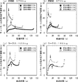
- FIG. 5 is a diagram showing the relationship between the elapsed time (s) from the start of discharging the raw material and the raw material lowering rate (mm / s).
- FIG. 5 (a) is charged with 676 kg of sintered ore as the main raw material.
- 5B shows a case where 473 kg of sintered ore is charged as a main raw material
- FIG. 5C shows a case where 123 kg of coke is charged as a main raw material
- FIG. 5D shows a case where 160 kg of coke is used as a main raw material.
- the flow control valve opening in FIGS. 5 (a) to 5 (d) means the opening of the flow regulating valve.
- the rate of decrease in the raw material in the rathole is the time from the start of discharge. Although it increases with the passage of time, it can be seen that it begins to decrease at a certain point in time.
- the time points at which the raw material lowering rate turns from increasing to decreasing are indicated by solid arrows.
- the raw material lowering speed starts to decrease from a certain point in time, as shown in FIG. 2 (b), first, the raw material deposited right above the discharge port is discharged to form a rat hole, and then This is because the raw material deposited around the inner peripheral surface of the rat hole collapses from the top and is discharged while flowing into the raw material surface in the rat hole region. That is, the present inventors calculate the raw material lowering rate from the raw material height measured by the level meter, and detect the time when the raw material lowering rate turns from increasing to decreasing. It was found that the raw material deposited around the inner peripheral surface could be detected when it was discharged from the upper part and discharged while flowing into the raw material surface in the rat hole region.
- the raw material lowering rate starts to increase again at the end of discharge.
- the area of the space portion (portion for storing the raw material) in the horizontal section is constant in the vicinity of the bottom outlet and at the top, but at the other intermediate portion at the bottom. By decreasing as you get closer.
- the rate of material reduction decreases from the increase depending on the shape of the top bunker, the top position of the raw material supplied to the top bunker (the method of charging the raw material into the top bunker), and the moisture content of the raw material.
- the point of time at which the point changes to fluctuates for this reason, in order to grasp the funnel flow discharge characteristics from the furnace top bunker, it is preferable to measure online changes in the raw material height of the rat hole during discharge of the raw material.
- the raw material charging conditions are not frequently changed during the steady operation of the blast furnace.
- emission characteristic is grasped
- the present invention has been completed on the basis of the above knowledge, and the following (1) and (2) blast furnace raw material charging apparatus, the first embodiment of the following (3) blast furnace raw material charging method, and The gist of the second embodiment of the raw material charging method of the blast furnace in the following (4).
- Two furnace top bunkers for temporarily storing raw materials to be charged in the blast furnace furnace, a first supply system for charging raw materials into these two furnace top bunkers, and discharge from the two furnace top bunkers
- a bell-less charging apparatus having a swirl chute for supplying a raw material to be supplied through a collecting hopper and charging the raw material into a blast furnace
- at least one of the two furnace top bunkers is a rathole.
- a raw material charging apparatus for a blast furnace comprising a chute for specific raw material and a flow rate adjusting valve for adjusting a flow rate of the specific raw material discharged from the specific raw material bunker.
- a method for charging a raw material of a blast furnace which detects a time point at which the change from an increase to a decrease is detected, and starts discharging the raw material from the specific raw material bunker until 15 seconds have elapsed since the time point was detected .
- V H (H 0 ⁇ H) / t (1) here, V H : Raw material lowering speed (average speed from start of discharge to time t) (mm / s), t: Elapsed time (s) from the start of material discharge H 0 : Raw material height (mm) at the start of material discharge, H: Raw material height at elapsed time t (mm)
- the condition for grasping the time A after grasping the time A that elapses from the start of the discharge until the rate at which the height of the raw material calculated by the equation (1) decreases changes from increase to decrease.
- the raw material discharge from the specific raw material bunker is performed between 15 seconds before the time A and the time A, which are obtained in advance.
- the raw material charging apparatus of the present invention and the raw material charging method using the same are charged into the furnace with an iron source or reducing material and a small amount of specific raw material to form a mixed layer, the main raw material and the specific raw material Can form a mixed layer having a uniform mixing ratio, and can improve the controllability of the charge distribution in the blast furnace furnace.
- FIG. 1 is a conceptual diagram illustrating a configuration example of a conventional parallel bunker type bellless charging device.
- 2A and 2B are diagrams showing a raw material supply order and a discharge order in the furnace top bunker.
- FIG. 2A shows a raw material supply order
- FIG. 2B shows a discharge order.
- FIG. 3 is a view showing a furnace top bunker of a model apparatus used in a test for detecting collapse of raw materials deposited around the inner peripheral surface of the rat hole.
- FIG. 4 is a diagram showing the relationship between the elapsed time from the start of discharging the raw material and the raw material height of the rat hole.
- FIG. 4 (a) shows a case where 676kg of sintered ore is charged as the main raw material.
- FIG. 5 is a diagram showing the relationship between the elapsed time from the start of discharging the raw material and the raw material lowering speed.
- FIG. 5 (a) shows the case where 676 kg of sintered ore is charged as the main raw material.
- Fig. 5 (c) shows a case where 123 kg of coke is charged as the main raw material
- Fig. 5 (d) shows a case where 160 kg of coke is charged as the main raw material. .
- FIG. 6 is a conceptual diagram of a parallel bunker bellless charging apparatus to which the present invention is applied.
- FIG. 7 is a view showing the state of the raw material charged in the furnace top bunker in the comparative example of the example.
- FIG. 8 is a diagram illustrating a relationship between elapsed time and coke content in a comparative example of the example.
- FIG. 9 is a diagram showing the relationship between the elapsed time and the coke content in Invention Example 1 and Invention Example 2 of Examples.
- FIG. 6 is a conceptual diagram of a parallel bunker bellless charging device to which the present invention is applied.
- the raw material charging apparatus shown in FIG. 6 has the same basic configuration as that of the raw material charging apparatus shown in FIG. 1 except that the raw material tank 1, the charging belt conveyor 2 and the switching chute 15 disposed on the top of the furnace top bunker. The illustration is omitted.
- the raw material charging apparatus shown in FIG. 6 is the same as the raw material charging apparatus shown in FIG. 1 for a specific raw material that temporarily stores a level meter 10 and a specific raw material 13 that are disposed immediately above the discharge port of the furnace top bunker 4.
- the bunker 12, the specific raw material chute 16 for charging the specific raw material discharged from the specific raw material bunker 12 into the rathole of the furnace top bunker 4, and the flow rate of the specific raw material discharged from the specific raw material bunker 12 are adjusted.
- a flow rate adjusting valve 11 is added.
- the raw material charging apparatus of the present invention includes two furnace top bunker 4 for temporarily storing the raw material charged in the blast furnace furnace, a first supply system for charging the raw material into the two furnace top bunker 4, In a bell-less charging apparatus having a swirl chute 8 in which raw materials discharged from two furnace top bunker 4 are supplied via a collecting hopper 7 and charged with the raw material into a blast furnace, In any one of the furnace bunker 4, a level meter 10 for measuring the height of the raw material of the rat hole, a specific raw material bunker 12 for temporarily storing the specific raw material, and a specific raw material discharged from the specific raw material bunker 12 A specific material chute 16 charged in the rathole of the furnace top bunker 4 having the level meter 10 and a flow rate adjusting valve 11 for adjusting the flow rate of the specific material discharged from the specific material bunker 12 are provided. It can be adopted embodiment.
- the furnace top bunker 4 has a level meter 10 for measuring the raw material height of the rat hole
- the raw material is discharged from the furnace top bunker 4 and charged into the blast furnace.
- the raw material lowering rate is calculated from the measured raw material height. That is, it is possible to detect when the raw material deposited around the inner peripheral surface of the rat hole collapses from the upper part due to a change in the funnel flow discharge characteristics and is discharged while flowing into the raw material surface in the rat hole region.
- a furnace top bunker 4 having a level meter 10 for measuring the height of a raw material in a rat hole, a specific raw material bunker 12 for temporarily storing a specific raw material, and a rat in the furnace top bunker 4 It has a chute 16 for specific raw material for charging the raw material into the hall, and a flow rate adjusting valve 11 for adjusting the flow rate of the specific raw material. Thereby, a specific raw material can be supplied to the rat hole of the furnace top bunker 4 at a desired flow rate.
- coke is stored in the specific raw material bunker 12, and ore is stored in the furnace top bunker in which the specific raw material is charged from the specific raw material bunker 12 among the two furnace top bunker 4.
- the coke is stored in another furnace top bunker 4 and the raw material is charged into the blast furnace.
- a raw material can be deposited by alternately forming a coke layer and a mixed layer in a blast furnace. Therefore, the raw material charging apparatus of the present invention can deposit the raw material by alternately forming a coke layer and a mixed layer in the blast furnace furnace by using two furnace top bunkers without increasing the number of furnace top bunkers. .
- the first supply system for charging the raw material into the two furnace top bunker 4 can adopt the same configuration as the raw material charging device shown in FIG. Specifically, a plurality of raw material tanks 1, a charging belt conveyor 2, a switching chute 15 that is arranged above the furnace top bunker and distributes the raw material conveyed by the charging belt conveyor 2 to any furnace top bunker, Can be configured.
- the raw material charging apparatus of the present invention preferably has a second supply system that branches from the first supply system and charges the raw material into the specific material bunker 12.
- the first supply system is configured by the plurality of raw material tanks 1, the charging belt conveyor 2, and the switching chute 15, the raw material is supplied from the switching chute to the specific raw material bunker.
- the material supply destination can be switched to any one of the two furnace top bunker and the specific material bunker by adding a route (second supply system) to be operated and operating the switching chute. Accordingly, the first supply system can be used to supply the raw material to the specific raw material bunker, and the equipment cost can be reduced.
- the raw material charging apparatus of the present invention is a specific raw material bunker in which one of the two top bunker 4 has a level meter 10 and temporarily stores a specific raw material. 12, a specific raw material chute 16 for charging the specific raw material discharged from the specific raw material bunker 12 into the rat hole of the furnace top bunker 4 having the level meter 10, and a specific raw material discharged from the specific raw material bunker 12 It is not limited to embodiment which has the flow regulating valve 11 which regulates the flow volume of.
- the raw material charging apparatus of the present invention employs an embodiment in which both of the two furnace top bunkers each have the level meter, the specific raw material bunker, the specific raw material chute, and the flow control valve. it can.
- a mixed layer can be formed from any furnace top bunker, and the furnace top bunker for storing ore can be changed.
- one charging cycle in which a coke layer and a mixed layer are alternately formed in a blast furnace furnace is constituted by, for example, two divided cokes and one charging of ore. It is also possible to deal with the case where the furnace top bunker used for ore charging is replaced every charging cycle.
- the raw material charging apparatus of the present invention adopts an embodiment in which one of the two furnace top bunkers has a level meter or the like.
- 1st Embodiment of the raw material charging method of this invention is a method of charging a raw material into a blast furnace using the above-mentioned raw material charging apparatus of this invention, Comprising: Raw material discharge
- the raw material height of the rat hole formed with the raw material discharge is measured, and the rate at which the raw material height defined by the equation (1) decreases (raw material decreasing rate) is continuously calculated, A time point at which the raw material lowering rate changes from an increase to a decrease is detected, and material discharge from the specific material bunker is started until 15 seconds have passed since the time point detection.
- the raw material charging method in which the raw material is sequentially charged into the conventional furnace top bunker.
- the ratio between the main raw material and the specific raw material contained in the discharged raw material varies greatly with time.
- the specific raw material is not discharged at the initial stage of discharge, but only the main raw material is discharged. Appears, gradually decreases from the middle to the end of the discharge, and increases again at the end of the discharge.
- the first embodiment of the raw material charging method of the present invention measures the raw material height of the rat hole formed along with the raw material charging after starting the discharge of the raw material from the inside of the furnace top bunker. Then, the raw material lowering rate is continuously calculated, and the time point at which the raw material lowering rate changes from increasing to decreasing is detected. That is, the time point at which the raw material deposited around the inner peripheral surface of the rat hole collapses from the top due to a change in the funnel flow discharge characteristics and is discharged while flowing into the raw material surface in the rat hole region is detected.
- the material discharge from the specific material bunker 12 is started.
- most of the specific raw material charged in the furnace top bunker is mixed with the raw material in the rat hole region and the raw material that collapses from the periphery of the inner peripheral surface of the rat hole and flows into the raw material surface in the rat hole region. It is discharged from the outlet.
- 1st Embodiment of the raw material charging method of this invention is contained in the raw material discharged
- the ratio of the specific raw material can be made uniform.
- a mixed layer in which the main raw material and the specific raw material are in a uniform ratio can be formed. Controllability of object distribution can be improved.
- 1st Embodiment of the raw material charging method of this invention measures raw material height with a level meter online, and calculates a raw material fall speed continuously. For this reason, even if the time point at which the rate of decrease in raw material starts to increase or decreases due to changes in the raw material moisture content due to changes in the type or amount of raw materials or changes in weather, etc., the main raw material is identified in the blast furnace furnace. A mixed layer in which the raw material is in a uniform ratio can be formed.
- the formation of a mixed layer in which the main raw material and the specific raw material are in a uniform ratio is promoted in the blast furnace to improve the reaction efficiency and air permeability in the cohesive zone. From the viewpoint, it is preferable to start the discharge of the raw material from the specific material bunker immediately (simultaneously) after detecting the time when the raw material lowering rate changes from increasing to decreasing.
- the raw material reduction rate The material discharge from the specific material bunker is started (within 15 seconds) until 15 seconds elapse after the time point when the change from increase to decrease is detected.
- a second embodiment of the raw material charging method of the present invention is a method of charging a raw material into a blast furnace using the above-described raw material charging device of the present invention.
- the time A that has elapsed from the start of the material discharge from the start until the point at which the rate at which the material height calculated by the equation (1) decreases changes from an increase to a decrease is determined, and the time A is determined.
- material discharge from the specific raw material bunker is started from 15 seconds before the time A that has been grasped in advance to time A It is characterized by that.
- the time A that elapses from when raw material discharge is started to when the raw material decrease rate changes from increasing to decreasing is measured when the main raw material is discharged after being charged into the furnace top bunker in accordance with predetermined operating conditions. Can be obtained by measuring the raw material height of the rat hole formed in the furnace top bunker at regular time intervals and calculating the raw material lowering rate.
- the point at which the rate of reduction of the raw material starts to increase varies depending on the type of raw material, the charging amount, and the opening of the flow control valve provided in the furnace top bunker.
- the point at which the rate of reduction of the raw material starts to decrease varies depending on the shape of the top bunker, the top position of the raw material supplied to the top bunker and deposited, and the moisture content of the raw material.
- the time point at which the raw material lowering rate turns from increasing to decreasing is within a certain range. Therefore, in the second embodiment of the raw material charging method of the present invention, the conditions when the time A is grasped in advance and the raw material is charged from the furnace top bunker while charging the specific raw material into the furnace top bunker. The conditions for doing this are the same.
- the raw material when the raw material is charged from the inside of the furnace top bunker, the raw material is discharged from the specific raw material bunker between 15 seconds before the time A and the time A which is grasped in advance.
- the main raw material and the specific raw material included in the raw material discharged from the furnace top bunker even when starting the raw material discharge from the specific raw material bunker 15 seconds before the time A grasped in advance
- the desired ratio can be uniformly controlled.
- the ratio of the specific material contained in the material discharged from the furnace top bunker changes temporarily ( Phenomenon).
- the raw material discharge from the upper specific raw material bunker is started from 15 seconds before time A to time A.
- emitted from a furnace top bunker over a longer time is desired ratio and uniform. Can be controlled.
- the raw material charging method of the present invention among the conditions such as the type of raw material, the mixing ratio of the main raw material and the specific raw material, the operation of the flow rate adjustment valve provided in the furnace top bunker or the specific raw material bunker, and the tilting operation of the swivel chute Therefore, by appropriately selecting and adjusting the conditions, it is possible to cope with various charging conditions that vary depending on the operating state of the blast furnace.
- the swirl chute is operated to charge the raw material in the order of the furnace wall side, middle part, and center side in the blast furnace furnace, the ore and coke are mixed in the center part.
- the raw material charging method of the present invention can be applied.
- the coke supply from the specific material bunker to the furnace bunker should be completed earlier than the discharge of ore from the furnace bunker.
- the amount of coke charged into the specific material bunker may be reduced without changing the opening of the flow rate adjusting valve provided in the specific material bunker.
- the opening degree of the flow rate adjusting valve provided in the specific material bunker may be changed and increased without changing the amount of coke charged into the specific material bunker.
- the raw material charging method of the present invention can be applied.
- the opening of the flow control valve provided in the furnace top bunker to increase it, from the start of the raw material discharge from inside the furnace top bunker, until the time when the raw material decrease rate starts to increase and decreases
- the elapsed time can be shortened.
- the capacity of the specific raw material bunker should be 0.1 or more in terms of the ratio to the capacity of the furnace top bunker (capacity of the specific raw material bunker / capacity of the top bunker). preferable.
- the capacity of the specific raw material bunker is too large, the raw material charging equipment mainly including the raw material charging device becomes large and expensive, which is disadvantageous in terms of equipment cost.
- capacitance of the bunker for specific raw materials shall be 0.5 or less in ratio with respect to the capacity
- the present invention is not limited to the parallel bunker type bellless charging device described with reference to the embodiment, and can also be applied to a vertical bunker type bellless charging device.
- the level gauge is arranged right above the discharge port, and the discharge port A chute for specific raw material was arranged so that the specific raw material was charged immediately above the top.
- the rat hole is usually formed immediately above the discharge port of the furnace top bunker, but may be formed at other positions depending on the shape of the furnace top bunker. Even in this case, the present invention can be applied by confirming in advance the position where the rat hole is formed.
- the main bunker was charged with 676 kg of sintered ore as the main raw material, and the specific material bunker 12 was charged with 20 kg of coke.
- Example 1 of the present invention the flow rate adjustment valve included in the furnace top bunker was opened, and the discharge of the raw material from the furnace top bunker was started with the opening degree kept constant. At that time, the raw material height of the rat hole formed just above the discharge port was measured every second with a level meter, and the raw material lowering rate was continuously calculated by the above equation (1).
- Example 1 of the present invention at the same time that the time point at which the raw material lowering rate changes from increasing to decreasing is detected, the flow rate adjusting valve provided in the specific raw material bunker is opened, and the opening degree is kept constant, the rat from the specific raw material bunker to the furnace bunker rat Specific raw materials were discharged toward the center of the hall.
- the specific raw material is utilized by using the time A that elapses from the start of the raw material discharge from the inside of the furnace bunker grasped by the present invention example 1 until the time when the raw material lowering rate changes from increasing to decreasing. Started to discharge raw materials from bunker.
- the time A elapsed from the start of the discharge of the raw material from the inside of the furnace top bunker to the time when the raw material lowering rate changed from increasing to decreasing was 35 seconds.
- the flow rate adjustment valve provided in the furnace top bunker is opened, and the opening degree is made constant.
- Raw material discharge from the top bunker started.
- the specified raw material is 15 seconds before the time A that has been grasped in advance has elapsed since the start of material discharge from the furnace bunker (when 20 seconds have passed since the material discharge from the furnace bunker started)
- the flow control valve of the bunker was opened, and the specific material was discharged from the bunker for the specific material toward the center of the rathole of the top bunker with the opening degree kept constant.
- the specific material bunker is provided so that the time when all ores are discharged from the furnace top bunker and the time when all coke is discharged from the specific material bunker are the same.
- the opening of the flow control valve was set.
- the ore as the main raw material was charged into the furnace bunker, and then the coke as the specific raw material was charged.
- FIG. 7 is a view showing the state of the raw material charged into the furnace top bunker in the comparative example.
- the layer 13 made of coke was formed on the layer 14 made of ore in the furnace top bunker.
- the flow adjustment valve provided in the furnace bunker is opened, the opening is kept constant, and the material discharge from the furnace bunker is started. All the raw materials were discharged.
- FIG. 8 is a diagram showing the relationship between the elapsed time and the coke content in the comparative example.
- the elapsed time shown in FIG. 8 is a relative value, where 0 is the time when material discharge from the furnace top bunker is started, and 1 is the time when material discharge is completed from the furnace top bunker (when all materials are discharged). To do.
- FIG. 9 is a diagram showing the relationship between the elapsed time and the coke content in Invention Example 1 and Invention Example 2.
- the elapsed time shown in FIG. 9 is a relative value in the same manner as in FIG. 8, and is 0 when the material discharge from the furnace top bunker is started, and when the material discharge is finished from the furnace top bunker (all the materials are discharged). 1).
- the coke content is about 4 to 7% after the elapsed time of about 0.6, and in the present invention example 2, it is about 5 to 7% after the elapsed time of about 0.5. It was confirmed that the mixing ratio in the raw material discharged from the furnace top bunker aimed at by the present invention can be made uniform.
- Example 2 of the present invention when the timing of starting the discharge of coke from the specific material bunker is further advanced, the conventional discharge pattern having a large peak as shown in FIG. 8 approaches.
- the raw material from the specific raw material bunker is between 15 seconds before the time when the raw material lowering rate grasped in advance changes from increasing to decreasing until this time. Start discharging.
- the raw material charging apparatus of the present invention and the raw material charging method using the same are charged into the furnace with an iron source or a reducing material and a small amount of specific raw material to form a mixed layer, the main raw material and the specific raw material Can form a mixed layer having a uniform mixing ratio, and the controllability of the charge distribution in the blast furnace can be improved.
- the raw material charging apparatus of the present invention and the raw material charging method using the same are applied to form a mixed layer of ore and coke in the furnace, so that the reduction reaction is performed in the cohesive zone. While promoting, air permeability can be improved and it can contribute greatly to the productivity improvement of a blast furnace.
- 1 raw material tank
- 2 charging belt conveyor
- 3 charging raw material
- 4 Furnace top bunker
- 4a Discharge port
- 5 Flow rate regulating valve of the top bunker
- 6 Opening
- 7 Collecting hopper
- 8 Turning chute
- 8a central axis of the turning chute
- 9 blast furnace
- 9a central axis of the blast furnace
- 10 Level meter 11: Flow control valve for specific material bunker
- 13 Specific raw material
- 14 Main raw material (ore)
- 15 Switching chute
- 16 Chute for specific raw materials
Abstract
Description
VH=(H0-H)/t ・・・(1)
VH=(H0-H)/t ・・・(1)
ここで、
VH:原料低下速度(排出開始から時刻tまでの平均速度)(mm/s)、
t:原料の排出開始時からの経過時間(s)、
H0:原料の排出開始時における原料高さ(mm)、
H:経過時間tにおける原料高さ(mm)
本試験では、高炉容積5,370m3の5.6分の1縮尺である並列バンカー式ベルレス装入模型装置を用いた。ベルレス装入模型装置の炉頂バンカーの形状は、前記図3に示した通りである。このベルレス装入模型装置に、前記図6に示す原料装入装置と同様に、炉頂バンカーの排出口の真上にレベル計(非接触式レーザー距離計)と、特定原料を一旦貯留する特定原料用バンカーと、特定原料用バンカーから排出される特定原料を炉頂バンカーのラットホールに装入する特定原料用シュートと、特定原料用バンカーから排出される特定原料の流量を調整する流量調整弁とを設けた。炉頂バンカーに主原料として鉱石である焼結鉱676kgを装入し、特定原料用バンカー12にコークス20kgを装入した。
本発明例および比較例ともに、炉頂バンカーの原料排出を開始してから試験終了までの間について約6秒毎に、炉頂バンカーから排出された原料から4~6kgの試料を採取した。採取した試料について、磁選、および目視によりコークスを分離して質量を計測し、原料のコークス含有率(質量%)を算出した。
図8は、比較例における経過時間と、コークス含有率との関係を示す図である。図8に示す経過時間は、相対値であり、炉頂バンカーから原料排出を開始した時点を0とし、炉頂バンカーから原料排出を終了した時点(全ての原料が排出された時点)を1とする。
4:炉頂バンカー、 4a:排出口、 5:炉頂バンカーの流量調整弁、
6:開口、 7:集合ホッパー、 8:旋回シュート、
8a:旋回シュートの中心軸、 9:高炉、 9a:高炉の中心軸、
10:レベル計、 11:特定原料用バンカーの流量調整弁、
12:特定原料用バンカー、 13:特定原料、
14:主原料(鉱石)、 15:切替シュート、
16:特定原料用シュート
Claims (4)
- 高炉炉内に装入する原料を一旦貯留するための2つの炉頂バンカーと、この2つの炉頂バンカーに原料を装入する第1供給系統と、前記2つの炉頂バンカーから排出される原料が集合ホッパーを介して供給され、当該原料を高炉に装入する旋回シュートとを有するベルレス式装入装置において、
前記2つの炉頂バンカーのうちで少なくとも一方の炉頂バンカーがラットホールの原料高さを測定するレベル計と、特定原料を一旦貯留する特定原料用バンカーと、当該特定原料用バンカーから排出される特定原料を前記レベル計を有する炉頂バンカーのラットホールに装入する特定原料用シュートと、前記特定原料用バンカーから排出される特定原料の流量を調整する流量調整弁とを有することを特徴とする高炉の原料装入装置。 - さらに前記第1供給系統から分岐して前記特定原料用バンカーに原料を装入する第2供給系統を有することを特徴とする請求項1に記載の高炉の原料装入装置。
- 請求項1または2に記載の高炉の原料装入装置を用いて高炉へ原料を装入する方法であって、
前記レベル計を有する炉頂バンカー内からの原料排出に際し、当該原料排出に伴って形成されるラットホールの原料高さを計測して下記(1)式により規定される原料高さが低下する速度を連続的に算出し、当該原料高さが低下する速度が増加から減少に変化する時点を検出し、前記時点を検出してから15秒経過するまでの間に前記特定原料用バンカーからの原料排出を開始することを特徴とする高炉の原料装入方法。
VH=(H0-H)/t ・・・(1)
ここで、
VH:原料低下速度(排出開始から時刻tまでの平均速度)(mm/s)、
t:原料の排出開始時からの経過時間(s)、
H0:原料の排出開始時における原料高さ(mm)、
H:経過時間tにおける原料高さ(mm) - 請求項1または2に記載の高炉の原料装入装置を用いて高炉へ原料を装入する方法であって、
事前に、前記レベル計を有する炉頂バンカー内からの原料排出を開始してから、前記(1)式により算出される原料高さが低下する速度が増加から減少に変化する時点までに経過する時間Aを把握しておき、
前記時間Aを把握した条件と同一条件で行う前記レベル計を有する炉頂バンカー内からの原料装入に際し、事前に把握した前記時間Aの15秒前から前記時間Aまでの間で前記特定原料用バンカーからの原料排出を開始することを特徴とする高炉の原料装入方法。
Priority Applications (3)
| Application Number | Priority Date | Filing Date | Title |
|---|---|---|---|
| BR112013028519A BR112013028519B8 (pt) | 2011-05-31 | 2012-05-25 | aparelho de carregamento de carga para um alto forno, em um aparelho de carga sem cone, e método de carregamento de carga em um alto forno usando o referido aparelho de carregamento de carga |
| JP2013517858A JP5585729B2 (ja) | 2011-05-31 | 2012-05-25 | 高炉の原料装入装置およびそれを用いた原料装入方法 |
| CN201280010998.2A CN103403193B (zh) | 2011-05-31 | 2012-05-25 | 高炉的原料装入装置以及使用该原料装入装置的原料装入方法 |
Applications Claiming Priority (2)
| Application Number | Priority Date | Filing Date | Title |
|---|---|---|---|
| JP2011-121211 | 2011-05-31 | ||
| JP2011121211 | 2011-05-31 |
Publications (1)
| Publication Number | Publication Date |
|---|---|
| WO2012164889A1 true WO2012164889A1 (ja) | 2012-12-06 |
Family
ID=47258765
Family Applications (1)
| Application Number | Title | Priority Date | Filing Date |
|---|---|---|---|
| PCT/JP2012/003423 WO2012164889A1 (ja) | 2011-05-31 | 2012-05-25 | 高炉の原料装入装置およびそれを用いた原料装入方法 |
Country Status (4)
| Country | Link |
|---|---|
| JP (1) | JP5585729B2 (ja) |
| CN (1) | CN103403193B (ja) |
| BR (1) | BR112013028519B8 (ja) |
| WO (1) | WO2012164889A1 (ja) |
Cited By (1)
| Publication number | Priority date | Publication date | Assignee | Title |
|---|---|---|---|---|
| WO2016190155A1 (ja) * | 2015-05-28 | 2016-12-01 | Jfeスチール株式会社 | 高炉への原料装入装置 |
Families Citing this family (5)
| Publication number | Priority date | Publication date | Assignee | Title |
|---|---|---|---|---|
| EP3394690B1 (de) | 2015-12-21 | 2020-04-01 | TGW Logistics Group GmbH | Verfahren zum sortieren von förderobjekten auf einer förderanlage |
| WO2017108900A1 (de) * | 2015-12-21 | 2017-06-29 | Tgw Logistics Group Gmbh | Verfahren zum sortieren von förderobjekten auf einer förderanlage mittels zeitsteuerung |
| EP3760744B1 (en) * | 2018-03-30 | 2023-09-06 | JFE Steel Corporation | Method for loading raw materials into blast furnace |
| BR102021000742A2 (pt) | 2021-01-15 | 2022-07-26 | Tecnored Desenvolvimento Tecnologico S.A. | Sistema e método de distribuição de cargas em um forno metalúrgico |
| CN116287512A (zh) * | 2022-09-05 | 2023-06-23 | 武安市裕华钢铁有限公司 | 一种高炉冶炼炉顶设备及旋转布料溜槽 |
Citations (4)
| Publication number | Priority date | Publication date | Assignee | Title |
|---|---|---|---|---|
| JPH02259005A (ja) * | 1989-03-31 | 1990-10-19 | Kawasaki Steel Corp | 高炉における原料装入方法 |
| JP2001192714A (ja) * | 2000-01-12 | 2001-07-17 | Kobe Steel Ltd | 高炉への原料装入方法 |
| JP2004010980A (ja) * | 2002-06-07 | 2004-01-15 | Sumitomo Metal Ind Ltd | 高炉の操業方法およびベルレス式装入装置 |
| JP2010150642A (ja) * | 2008-12-26 | 2010-07-08 | Jfe Steel Corp | 高炉への原料装入方法 |
Family Cites Families (6)
| Publication number | Priority date | Publication date | Assignee | Title |
|---|---|---|---|---|
| JPS63204093A (ja) * | 1987-02-20 | 1988-08-23 | 日本鋼管株式会社 | 竪型炉への原料装入装置 |
| JPH01309909A (ja) * | 1988-06-09 | 1989-12-14 | Kawasaki Steel Corp | 高炉への原料装入方法 |
| JPH0772286B2 (ja) * | 1988-12-21 | 1995-08-02 | 川崎製鉄株式会社 | ベルレス高炉の炉頂装入方法 |
| JPH0665620A (ja) * | 1992-08-18 | 1994-03-08 | Sumitomo Metal Ind Ltd | ベルレス高炉における原料装入方法 |
| TWI239355B (en) * | 2002-08-29 | 2005-09-11 | Jfe Steel Corp | Method for charging material into blast furnace with distributing chute instead of bells |
| CN201678691U (zh) * | 2010-01-26 | 2010-12-22 | 沈阳东方钢铁有限公司 | 一种高炉无钟布料装置 |
-
2012
- 2012-05-25 JP JP2013517858A patent/JP5585729B2/ja active Active
- 2012-05-25 CN CN201280010998.2A patent/CN103403193B/zh not_active Expired - Fee Related
- 2012-05-25 WO PCT/JP2012/003423 patent/WO2012164889A1/ja active Application Filing
- 2012-05-25 BR BR112013028519A patent/BR112013028519B8/pt not_active IP Right Cessation
Patent Citations (4)
| Publication number | Priority date | Publication date | Assignee | Title |
|---|---|---|---|---|
| JPH02259005A (ja) * | 1989-03-31 | 1990-10-19 | Kawasaki Steel Corp | 高炉における原料装入方法 |
| JP2001192714A (ja) * | 2000-01-12 | 2001-07-17 | Kobe Steel Ltd | 高炉への原料装入方法 |
| JP2004010980A (ja) * | 2002-06-07 | 2004-01-15 | Sumitomo Metal Ind Ltd | 高炉の操業方法およびベルレス式装入装置 |
| JP2010150642A (ja) * | 2008-12-26 | 2010-07-08 | Jfe Steel Corp | 高炉への原料装入方法 |
Cited By (3)
| Publication number | Priority date | Publication date | Assignee | Title |
|---|---|---|---|---|
| WO2016190155A1 (ja) * | 2015-05-28 | 2016-12-01 | Jfeスチール株式会社 | 高炉への原料装入装置 |
| JP2016222960A (ja) * | 2015-05-28 | 2016-12-28 | Jfeスチール株式会社 | 高炉への原料装入装置 |
| KR102062969B1 (ko) | 2015-05-28 | 2020-01-06 | 제이에프이 스틸 가부시키가이샤 | 고로에의 원료 장입 장치 |
Also Published As
| Publication number | Publication date |
|---|---|
| CN103403193A (zh) | 2013-11-20 |
| CN103403193B (zh) | 2015-02-18 |
| JPWO2012164889A1 (ja) | 2015-02-23 |
| JP5585729B2 (ja) | 2014-09-10 |
| BR112013028519B1 (pt) | 2019-01-22 |
| BR112013028519A2 (pt) | 2017-01-10 |
| BR112013028519B8 (pt) | 2019-09-17 |
Similar Documents
| Publication | Publication Date | Title |
|---|---|---|
| JP5585729B2 (ja) | 高炉の原料装入装置およびそれを用いた原料装入方法 | |
| JP5440077B2 (ja) | ベルレス高炉への原料装入方法 | |
| CN107614707B (zh) | 向高炉装入原料的装置 | |
| TWI239355B (en) | Method for charging material into blast furnace with distributing chute instead of bells | |
| CN104302788B (zh) | 向高炉装入原料的方法 | |
| JP5861392B2 (ja) | 高炉操業方法 | |
| JP5481891B2 (ja) | ベルレス高炉への原料装入方法 | |
| JP5387278B2 (ja) | 高炉の原料装入方法 | |
| JP6943339B2 (ja) | ベルレス高炉の原料装入方法および高炉操業方法 | |
| JP5338309B2 (ja) | 高炉への原料装入方法 | |
| JP5135959B2 (ja) | 高炉への原料装入方法及び原料装入装置 | |
| CN111989411B (zh) | 高炉的原料装入方法 | |
| JP6102497B2 (ja) | ベルレス高炉の原料装入方法 | |
| JP6601511B2 (ja) | 高炉操業方法 | |
| JP2009299154A (ja) | ベルレス高炉の原料装入装置および原料装入方法 | |
| JP6558519B1 (ja) | 高炉の原料装入方法 | |
| JP6627718B2 (ja) | 高炉への原料装入方法 | |
| JP5853904B2 (ja) | ベル式高炉の原料装入方法 | |
| JP2001279309A (ja) | 高炉への原料装入方法 | |
| JP5056563B2 (ja) | 高炉操業方法 | |
| JP5217650B2 (ja) | 高炉への原料装入方法 | |
| JP6558518B1 (ja) | 高炉の原料装入方法 | |
| JP2005264292A (ja) | ベルレス原料装入装置を備えた高炉での原料装入方法 | |
| JP2005248278A (ja) | 高炉操業方法 | |
| JP2009299155A (ja) | ベルレス高炉の原料装入装置および原料装入方法 |
Legal Events
| Date | Code | Title | Description |
|---|---|---|---|
| 121 | Ep: the epo has been informed by wipo that ep was designated in this application |
Ref document number: 12792976 Country of ref document: EP Kind code of ref document: A1 |
|
| ENP | Entry into the national phase |
Ref document number: 2013517858 Country of ref document: JP Kind code of ref document: A |
|
| NENP | Non-entry into the national phase |
Ref country code: DE |
|
| REG | Reference to national code |
Ref country code: BR Ref legal event code: B01A Ref document number: 112013028519 Country of ref document: BR |
|
| 122 | Ep: pct application non-entry in european phase |
Ref document number: 12792976 Country of ref document: EP Kind code of ref document: A1 |
|
| ENP | Entry into the national phase |
Ref document number: 112013028519 Country of ref document: BR Kind code of ref document: A2 Effective date: 20131105 |