WO2012164856A1 - 二酸化炭素回収方法および装置 - Google Patents
二酸化炭素回収方法および装置 Download PDFInfo
- Publication number
- WO2012164856A1 WO2012164856A1 PCT/JP2012/003275 JP2012003275W WO2012164856A1 WO 2012164856 A1 WO2012164856 A1 WO 2012164856A1 JP 2012003275 W JP2012003275 W JP 2012003275W WO 2012164856 A1 WO2012164856 A1 WO 2012164856A1
- Authority
- WO
- WIPO (PCT)
- Prior art keywords
- carbon dioxide
- water vapor
- desorption
- adsorbent
- steam
- Prior art date
- Legal status (The legal status is an assumption and is not a legal conclusion. Google has not performed a legal analysis and makes no representation as to the accuracy of the status listed.)
- Ceased
Links
Images

Classifications
-
- B—PERFORMING OPERATIONS; TRANSPORTING
- B01—PHYSICAL OR CHEMICAL PROCESSES OR APPARATUS IN GENERAL
- B01D—SEPARATION
- B01D53/00—Separation of gases or vapours; Recovering vapours of volatile solvents from gases; Chemical or biological purification of waste gases, e.g. engine exhaust gases, smoke, fumes, flue gases, aerosols
- B01D53/02—Separation of gases or vapours; Recovering vapours of volatile solvents from gases; Chemical or biological purification of waste gases, e.g. engine exhaust gases, smoke, fumes, flue gases, aerosols by adsorption, e.g. preparative gas chromatography
- B01D53/04—Separation of gases or vapours; Recovering vapours of volatile solvents from gases; Chemical or biological purification of waste gases, e.g. engine exhaust gases, smoke, fumes, flue gases, aerosols by adsorption, e.g. preparative gas chromatography with stationary adsorbents
-
- B—PERFORMING OPERATIONS; TRANSPORTING
- B01—PHYSICAL OR CHEMICAL PROCESSES OR APPARATUS IN GENERAL
- B01D—SEPARATION
- B01D2257/00—Components to be removed
- B01D2257/50—Carbon oxides
- B01D2257/504—Carbon dioxide
-
- B—PERFORMING OPERATIONS; TRANSPORTING
- B01—PHYSICAL OR CHEMICAL PROCESSES OR APPARATUS IN GENERAL
- B01D—SEPARATION
- B01D2258/00—Sources of waste gases
- B01D2258/02—Other waste gases
- B01D2258/0283—Flue gases
-
- B—PERFORMING OPERATIONS; TRANSPORTING
- B01—PHYSICAL OR CHEMICAL PROCESSES OR APPARATUS IN GENERAL
- B01D—SEPARATION
- B01D2259/00—Type of treatment
- B01D2259/40—Further details for adsorption processes and devices
- B01D2259/40001—Methods relating to additional, e.g. intermediate, treatment of process gas
-
- B—PERFORMING OPERATIONS; TRANSPORTING
- B01—PHYSICAL OR CHEMICAL PROCESSES OR APPARATUS IN GENERAL
- B01D—SEPARATION
- B01D2259/00—Type of treatment
- B01D2259/40—Further details for adsorption processes and devices
- B01D2259/40011—Methods relating to the process cycle in pressure or temperature swing adsorption
- B01D2259/40043—Purging
- B01D2259/4005—Nature of purge gas
- B01D2259/40052—Recycled product or process gas
- B01D2259/40054—Recycled product or process gas treated before its reuse
-
- B—PERFORMING OPERATIONS; TRANSPORTING
- B01—PHYSICAL OR CHEMICAL PROCESSES OR APPARATUS IN GENERAL
- B01D—SEPARATION
- B01D2259/00—Type of treatment
- B01D2259/40—Further details for adsorption processes and devices
- B01D2259/40083—Regeneration of adsorbents in processes other than pressure or temperature swing adsorption
- B01D2259/40086—Regeneration of adsorbents in processes other than pressure or temperature swing adsorption by using a purge gas
-
- B—PERFORMING OPERATIONS; TRANSPORTING
- B01—PHYSICAL OR CHEMICAL PROCESSES OR APPARATUS IN GENERAL
- B01D—SEPARATION
- B01D2259/00—Type of treatment
- B01D2259/40—Further details for adsorption processes and devices
- B01D2259/402—Further details for adsorption processes and devices using two beds
-
- B—PERFORMING OPERATIONS; TRANSPORTING
- B01—PHYSICAL OR CHEMICAL PROCESSES OR APPARATUS IN GENERAL
- B01D—SEPARATION
- B01D53/00—Separation of gases or vapours; Recovering vapours of volatile solvents from gases; Chemical or biological purification of waste gases, e.g. engine exhaust gases, smoke, fumes, flue gases, aerosols
- B01D53/02—Separation of gases or vapours; Recovering vapours of volatile solvents from gases; Chemical or biological purification of waste gases, e.g. engine exhaust gases, smoke, fumes, flue gases, aerosols by adsorption, e.g. preparative gas chromatography
- B01D53/04—Separation of gases or vapours; Recovering vapours of volatile solvents from gases; Chemical or biological purification of waste gases, e.g. engine exhaust gases, smoke, fumes, flue gases, aerosols by adsorption, e.g. preparative gas chromatography with stationary adsorbents
- B01D53/047—Pressure swing adsorption
-
- B—PERFORMING OPERATIONS; TRANSPORTING
- B01—PHYSICAL OR CHEMICAL PROCESSES OR APPARATUS IN GENERAL
- B01D—SEPARATION
- B01D53/00—Separation of gases or vapours; Recovering vapours of volatile solvents from gases; Chemical or biological purification of waste gases, e.g. engine exhaust gases, smoke, fumes, flue gases, aerosols
- B01D53/34—Chemical or biological purification of waste gases
- B01D53/46—Removing components of defined structure
- B01D53/62—Carbon oxides
-
- Y—GENERAL TAGGING OF NEW TECHNOLOGICAL DEVELOPMENTS; GENERAL TAGGING OF CROSS-SECTIONAL TECHNOLOGIES SPANNING OVER SEVERAL SECTIONS OF THE IPC; TECHNICAL SUBJECTS COVERED BY FORMER USPC CROSS-REFERENCE ART COLLECTIONS [XRACs] AND DIGESTS
- Y02—TECHNOLOGIES OR APPLICATIONS FOR MITIGATION OR ADAPTATION AGAINST CLIMATE CHANGE
- Y02C—CAPTURE, STORAGE, SEQUESTRATION OR DISPOSAL OF GREENHOUSE GASES [GHG]
- Y02C20/00—Capture or disposal of greenhouse gases
- Y02C20/40—Capture or disposal of greenhouse gases of CO2
Definitions
- the present invention relates to a carbon dioxide recovery method and apparatus, and more particularly, a carbon dioxide capable of recovering carbon dioxide with low energy from a gas to be treated containing carbon dioxide discharged from a power plant equipped with a boiler and a steam turbine.
- the present invention relates to a carbon recovery method and apparatus.
- Reducing carbon dioxide emissions is a global issue, and while solar energy, wind power, geothermal heat, etc. are being developed, combustion emitted when using fossil fuels such as coal Development and demonstration tests of technologies for separating and collecting carbon dioxide in exhaust gas and accumulating it underground are underway internationally. Particularly for facilities that emit large amounts of carbon dioxide such as thermal power plants, development of large-scale carbon dioxide separation and recovery technology is required.
- FIG. 6 schematically shows a power plant and a conventional carbon dioxide separation and recovery device attached to the power plant.
- the steam generated by the boiler 3 is guided to the steam turbine 4 to generate power by turning the generator 5, and the steam that has finished work in the steam turbine 4 is condensed.
- the condenser (condenser) 6 After being condensed by the condenser (condenser) 6, it is returned to the boiler 3 again.
- combustion exhaust gas from the boiler 3 is supplied from the lower part of the absorption tank 7 of the carbon dioxide separation and recovery device 2 after cooling, and here is an amine system such as monoethanolamine which is a carbon dioxide absorbent for recovering carbon dioxide. For example, it comes into contact with the aqueous solution at 40 ° C.
- the combustion exhaust gas after the recovery of carbon dioxide is sent from the upper part of the absorption tank 7 to the chimney 11 and then discharged into the atmosphere.
- the amine-based aqueous solution that has absorbed carbon dioxide is sent to the regeneration tank 8 where carbon dioxide is desorbed and recovered from the amine-based aqueous solution.
- the desorption recovery of carbon dioxide is performed by heating the amine-based aqueous solution to 120 ° C.
- high-temperature steam at 120 ° C. or higher extracted from the steam turbine 4 of the power plant 1 is used as a heating source.
- the high-temperature steam extracted from the steam turbine 4 is supplied to the heat exchanger 9, and the desorption recovery of carbon dioxide from the amine aqueous solution is performed in the regeneration tank 8 by the heating medium generated by the heat exchange.
- Non-patent Document 1 Such a conventional carbon dioxide separation and recovery device 2 is known to require a large amount of heat such as 2.5 to 4.0 GJ / CO 2 tons for desorption of carbon dioxide (Non-patent Document 1). .
- steam having a heat quantity necessary for the desorption is extracted from the steam turbine 4, there is a problem that the power generation amount in the power plant 1 is reduced.
- an object of the present invention is to provide a carbon dioxide recovery method capable of desorbing and recovering carbon dioxide with low energy from a gas to be processed containing carbon dioxide discharged from a power plant equipped with a boiler and a steam turbine. Is to provide a device.
- the carbon dioxide recovery method of the present invention is a carbon dioxide that performs adsorption and desorption of carbon dioxide using a carbon dioxide adsorbent from a treated gas containing carbon dioxide discharged from a power plant equipped with a boiler and a steam turbine.
- the carbon dioxide recovery device of the present invention performs adsorption and desorption of carbon dioxide from a gas to be treated containing carbon dioxide discharged from a power plant equipped with a boiler and a steam turbine, using a carbon dioxide adsorbent. It is a carbon dioxide recovery device, wherein at least one adsorbent filling tank filled with the carbon dioxide adsorbent, and a gas to be treated containing carbon dioxide is supplied to the adsorbent filling tank.
- a desorption water vapor preparation means for preparing desorption water vapor for desorbing carbon dioxide, and supplying desorption water vapor to the adsorbent filling tank
- Desorption water vapor supply means for desorbing carbon dioxide from the carbon dioxide adsorbent, and the desorption water vapor preparation means is discharged from a steam turbine outlet. It is characterized by the preparation of a desorption vapor from a portion of outlet steam that.
- the desorption steam is prepared from a part of the outlet steam discharged from the steam turbine outlet, so that the amount of carbon dioxide can be reduced without reducing the power generation amount of the power plant. Desorption recovery can be performed.
- the desorption of carbon dioxide is preferably performed under a negative pressure. This is because the outlet steam discharged from the steam turbine outlet is usually at a low temperature and low pressure.
- the part of the outlet steam discharged from the steam turbine outlet is compressed and heated, and the water vapor for desorption is performed using the water vapor after the compression and heating process. It can be configured to be prepared. In that case, it is preferable that the desorption water vapor prepared using the water vapor after the compression / heating step is a saturated vapor of 7 to 70 kPa.
- the desorption water vapor prepared using the water vapor after the compression / heating step is a saturated vapor of 7 to 70 kPa.
- the desorption water vapor can be prepared from water by heat exchange with the water vapor after the compression / heating step.
- desorption and recovery of carbon dioxide can be performed without adversely affecting the power plant by returning the steam or water after heat exchange to the power plant.
- the desorption water vapor can be prepared by pouring water into the water vapor after the compression / heating step. In this case, heat exchange is unnecessary, and the carbon dioxide recovery device can be simplified.
- the desorption water vapor is supplied from one end of the carbon dioxide adsorbent to the other end, and the carbon dioxide
- the supply of the desorption water vapor can be stopped. Thereby, the water vapor for desorption can be used effectively without waste.
- the amount of heat contained in the exit steam of the steam turbine that has been discarded without being used conventionally can be used as a heat source for desorption recovery of carbon dioxide. It is possible to desorb and recover carbon dioxide without reducing the power generation amount of the power plant. Further, by using the outlet steam from the outlet of the steam turbine by compressing and heating it, it is possible to increase the steam energy (energy that can be used for CO 2 desorption recovery) obtained with respect to the required compression energy. Furthermore, the condensation load of the condenser (condenser) for condensing the outlet steam discharged from the steam turbine outlet of the power plant is also reduced.
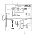
- FIG. 1 is a schematic configuration diagram of a carbon dioxide recovery device and a power plant according to an embodiment of the present invention.
- FIG. 2 is a schematic diagram showing an energy balance when a heat exchanger is used as a cooler in the carbon dioxide recovery apparatus of FIG.
- FIG. 3 is a schematic diagram showing an energy balance when a temperature-reduced water injector is used as a cooler in the carbon dioxide recovery apparatus of FIG.
- FIG. 4 is a schematic configuration diagram of a carbon dioxide recovery device and a power plant according to another embodiment of the present invention.
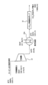
- FIG. 5 is an explanatory diagram showing a state in which a portion where carbon dioxide is desorbed moves when water vapor is supplied to a carbon dioxide adsorbent composed of an amine-carrying adsorbent.
- FIG. 6 is a schematic configuration diagram showing a power plant and a conventional carbon dioxide recovery device attached to the power plant.
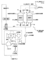
- FIG. 1 shows a schematic configuration of a carbon dioxide recovery device 20 and a power plant 1 according to an embodiment of the present invention.
- the power plant 1 includes a boiler 3 that burns fossil fuel such as coal to generate steam, a steam turbine 4 that rotates the generator 5 using the steam generated in the boiler 3, and the steam turbine 4 has finished turning.
- a condenser (condenser) 6 for condensing the water vapor after. The water condensed and liquefied by the condenser 6 is returned to the boiler 3 again.
- the condenser 6 is supplied with cooling water that circulates between the condenser 6 and the cooling tower 13.
- the carbon dioxide recovery device 20 of this embodiment adsorbs carbon dioxide from the combustion exhaust gas generated in the boiler 3 of the power plant 1 and then desorbs and recovers it.
- the carbon dioxide recovery device 20 of the present embodiment includes two adsorbent filling tanks 21 and 31 that store carbon dioxide adsorbents for adsorbing and desorbing carbon dioxide, respectively.
- the combustion exhaust gas discharged from the boiler 3 of the power plant 1 is desulfurized and dedusted, and then cooled to about 40 ° C. by the cooler 38.
- the combustion exhaust gas after cooling is supplied to one of the two adsorbent filling tanks 21 and 31, and carbon dioxide is adsorbed.
- a carbon dioxide adsorbing material carrying an amine compound such as monoethanolamine or diethanolamine is used.
- a line connecting the one adsorbent filling tank 21 and the cooler 38 is provided with a valve 22 for turning on and off the supply of the combustion exhaust gas sent from the cooler 38.
- a valve 23 is provided for exhausting the combustion exhaust gas that has finished adsorbing carbon dioxide when adsorbing carbon dioxide.
- a valve 25 for collecting the carbon dioxide desorbed when desorbing carbon dioxide is provided in the upper part of the adsorbent filling tank 21.
- a line connecting the other adsorbent filling tank 31 and the cooler 38 is provided with a valve 32 for turning on and off the supply of the combustion exhaust gas sent from the cooler 38, and is provided above the adsorbent filling tank 31.
- valve 33 for exhausting the combustion exhaust gas after adsorption of carbon dioxide when carbon dioxide is adsorbed.
- a valve 35 for recovering carbon dioxide desorbed when desorbing carbon dioxide is provided at the upper part of the adsorbent filling tank 31.
- a carbon dioxide recovery pump 27 for recovering carbon dioxide desorbed from the adsorbent filling tank 21 or 31 via the valve 25 or the valve 35 is further provided.
- the carbon dioxide recovery device 20 of the present invention includes a steam compressor 37 and a cooler 29 for using the outlet steam (so-called turbine exhaust) of the steam turbine 4. That is, in the carbon dioxide recovery device 20 of the present embodiment, part of the outlet steam discharged from the outlet of the steam turbine 4 of the power plant 1 branches before entering the condenser 6 and is sent to the carbon dioxide recovery device 20. It is configured to be.
- the branched water vapor is sent to the vapor compressor 37, where it is compressed and heated, and then sent to the cooler 29.
- the cooler 29 cools the steam that has been compressed and heated, thereby preparing desorption steam.
- the water vapor prepared by the cooler 29 is supplied to the adsorbent filling tank 21 or 31 through the valve 24 or the valve 34 when desorbing carbon dioxide.
- valve 22 and the valve 23 arranged above and below one adsorbent filling tank 21 are opened, and the valve 32 and the valve 33 arranged above and below the other adsorbent filling tank 31 are closed. Therefore, adsorption of carbon dioxide in the combustion exhaust gas is performed in the adsorbent filling tank 21. Further, since the valves 24 and 25 on the adsorbent filling tank 21 side are closed and the valves 34 and 35 on the adsorbent filling tank 31 side are opened, desorption of carbon dioxide is performed in the adsorbent filling tank 31. become.
- valve 22 and valve 23 When adsorbing carbon dioxide in combustion exhaust gas in the adsorbent filling tank 31 and desorbing carbon dioxide in the adsorbent filling tank 21, the valve 22 and valve 23 are closed, the valve 32 and valve 33 are opened, 24 and 25 are open, and valves 34 and 35 are closed.
- the water vapor when water vapor is continuously supplied, the water vapor is condensed in a layered portion having a low temperature located slightly above the lowermost portion, and carbon dioxide is desorbed from this portion.
- the layered portion in the carbon dioxide adsorbing material 19 where water vapor is condensed sequentially moves upward, and the desorption of carbon dioxide proceeds accordingly (FIG. 5B).
- the desorbed carbon dioxide gradually moves upward in the carbon dioxide adsorbing material 19 and gradually increases in concentration, and the concentration of gaseous carbon dioxide finally discharged by the carbon dioxide recovery pump 27 is almost 100%. It becomes.
- the desorption heat of carbon dioxide is theoretically about 1.7 MJ / kg CO 2 .
- the condensation heat of the steam because approximately 2.3MJ / kg steam, required amount of water vapor to 1.0kg releases CO 2, as shown below, the 0.74kg steam / kg CO 2 .
- FIG. 2 is an explanatory diagram showing the energy balance in the recovery of carbon dioxide when the heat exchanger 29a is used as the cooler 29 of FIG.
- FIG. 2 shows a case where carbon dioxide is recovered at 1 t / h.
- a part of the outlet steam sent from the outlet of the steam turbine 4 to the condenser 6 is taken out and sent to the steam compressor 37.
- the outlet steam before entering the condenser 6 is generally low-temperature and low-pressure saturated steam, and in the example shown in FIG. 2, saturated steam at 35 ° C. and 5.6 kPa is taken out at 0.89 t / h.
- Such low-temperature and low-pressure saturated steam is not used in a conventional power plant, and is returned to water by the condenser 6 without any work.
- the low-temperature and low-pressure saturated steam is compressed by the steam compressor 37 and the pressure is increased to a steam condition suitable for desorption of carbon dioxide.
- the pressure is increased until it becomes superheated steam at 183 ° C. and 20 kPa.
- the power required by the steam compressor 37 is 69 kW.
- the target saturated steam of 60 ° C. and 20 kPa is obtained as desorption steam.
- the supply amount of the desorption water vapor is 0.89 t / h.
- This saturated vapor is supplied to the adsorbent filling tank 21 or 31 shown in FIG. 1 and used for desorption of carbon dioxide. Furthermore, since carbon dioxide desorbed inside the adsorbent filling tank 21 or 31 is under reduced pressure, 45 kW of power is required in the carbon dioxide recovery pump 27 in order to take it out as a normal pressure gas.
- the steam of carbon dioxide desorption compresses the low-temperature steam at the outlet of the steam turbine and raises the temperature to a steam condition suitable for carbon dioxide desorption.
- Boosted the steam pressure at the turbine outlet is 5.6 kPa, and if it is supplied to the adsorbent as it is, no steam compression power is required.
- the pressure of carbon dioxide (100%) released here is also 5.6 kPa, in order to recover the carbon dioxide outside the system, a carbon dioxide separation / recovery pump is used and the atmospheric pressure is reduced from 5.6 kPa to atmospheric pressure. It is necessary to compress to (100 kPa).
- the temperature of the adsorbent rises due to the heat of adsorption generated when carbon dioxide is adsorbed by the adsorbent, and the extent is the concentration of carbon dioxide.
- the carbon dioxide concentration of the combustion exhaust gas of the thermal power plant is 10 to 15%, and in this case, the temperature of the adsorbent reaches 50 to 60 ° C. Since the desorption of carbon dioxide is performed immediately after the adsorption of carbon dioxide, the closer the regeneration temperature is to the adsorption temperature, the smaller the amount of heat consumed. For example, when the temperature after adsorption is 60 ° C.
- the vapor temperature is 80 ° C.
- energy is required to raise the temperature of the adsorbent by 20 ° C., and energy efficiency is reduced.
- the steam temperature is 40 ° C.
- the steam does not condense in the regeneration process, but passes through the adsorbent layer, and the energy efficiency decreases.
- the adsorbent temperature after adsorption depends on the exhaust gas temperature and the concentration of carbon dioxide as described above, and varies depending on the applied plant. Therefore, the regeneration temperature range in the present invention is not limited to COP.
- the temperature is preferably 40 ° C. to 90 ° C., more preferably 50 ° C. to 70 ° C., and the optimum temperature is about 60 ° C.
- FIG. 3 is an explanatory diagram showing the energy balance in the recovery of carbon dioxide when the reduced-temperature water injector 29b is used instead of the heat exchanger 29a in FIG. FIG. 3 also describes the case where carbon dioxide is recovered at 1 t / h.
- the temperature reducing water injector 29b injects normal temperature water into the superheated steam that has been compressed and heated by the steam compressor 37 to generate saturated steam at a predetermined temperature.
- the finally obtained saturated steam at 60 ° C. is obtained from both superheated steam that has been compressed and heated by the steam compressor 37 and water that is injected by the temperature-reduced water injector 29b.
- the amount of steam taken out from the steam turbine 4 is less than 0.89 t / h in the case of FIG. 2 and 0.81 t / h, and the difference is 0.08 t / h. It is the amount of water injected in the water injector 29b. Therefore, the compressor power in the steam compressor 37 is 63 kW, which is less than 69 kW in the case of FIG. Also in the case of FIG. 3, after being compressed by the steam compressor 37, it becomes superheated steam at 183 ° C. and 20 kPa. By injecting water into this superheated steam in the temperature-reduced water injector 29b, saturated steam at 60 ° C. and 20 kPa is obtained as desorption steam in the same manner as in FIG.
- the power in the carbon dioxide recovery pump 27 for taking out the desorbed carbon dioxide from the adsorbent filling tank 21 or 31 under reduced pressure as a normal pressure gas is 45 kW as in FIG.
- “Steam compression power” in the third row represents the power in the steam compressor 37, and the sum of “recovery pump power” and “steam compression power” is shown in the “necessary power” column along with the value after calorie conversion.
- the “used steam flow rate” in the fourth row is the flow rate of saturated steam guided from the steam turbine 4 to the steam compressor 37
- the “injected steam flow rate” in the fifth row is the water to be injected in the temperature-reduced water injector 29b. Is the flow rate.
- the “desorption steam flow rate” in the sixth row is the sum of the “used steam flow rate” and the “injection steam flow rate”.
- COP on the bottom line indicates how much desorption water vapor can be obtained with respect to the applied power (power of the steam compressor 37 and the carbon dioxide recovery pump 27).
- the COP increases as the temperature of the desorption water vapor decreases. However, since the desorption rate of carbon dioxide tends to decrease at low temperatures, it is not preferable to reduce the temperature too much. It can also be seen that the COP decreases as the temperature of the desorption water vapor increases, and a large amount of energy is required to obtain the desorption water vapor. Further, it is not preferable that the temperature of the desorption water vapor is increased because amine degradation is likely to occur. In particular, at 130 ° C., the COP becomes 1, and it cannot be said that water vapor is effectively used. From the results in Table 1, the temperature of the desorption steam is preferably in the range of 40 to 90 ° C. (saturated steam of 7 to 70 kPa), and in the range of 50 to 70 ° C. (saturated steam of 12 to 30 kPa). It is more preferable.
- waste steam before entering the condenser 6 that has not been used in the conventional power plant 1 is compressed and heated at a relatively low compression ratio. Therefore, even if power is consumed by the vapor compressor 37 and the carbon dioxide recovery pump 27, carbon dioxide can be desorbed and recovered with lower energy than before. Moreover, the condensation load in the condenser 6 of the power plant 1 is also reduced, and the amount of cooling water in the cooling tower 13 is also reduced.
- Table 2 shows a comparison of the amount of heat required for the separation and recovery of carbon dioxide between the conventional carbon dioxide recovery device and the carbon dioxide recovery device of the present invention.
- MEA absorption method MAA absorption method
- Non-Patent Document 1 it is understood that although the main power is not required, a part of the steam for power generation is extracted, so that the loss of steam energy is large.
- the steam consumption may be improved by the development of a new absorbent, it is understood that the loss of steam energy is not reduced because part of the steam for power generation is extracted.
- the carbon dioxide recovery device of the present embodiment the steam that has not been used before exiting the steam turbine 4 and entering the condenser 6 is used for the preparation of the desorption steam. It can be seen that a large energy reduction is achieved in spite of the need for power for compression heating to 60 ° C.
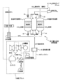
- FIG. 4 shows a schematic configuration of the carbon dioxide recovery device 40 and the power plant 1 according to another embodiment of the present invention.
- the point that the steam generator 39 is used instead of the cooler 29 and the point that the drain line 36 for returning to the condenser 6 generated in the steam generator 39 is provided are described above.
- This embodiment is different from the first embodiment, and the other points are the same as those of the embodiment of FIG. Accordingly, the components in FIG. 4 corresponding to those in FIG.
- the saturated steam before leaving the steam turbine 4 and entering the condenser 6 is compressed by the steam compressor 37 as in the embodiment of FIG. 1 to obtain superheated steam.
- This superheated steam is then led to the steam generator 39 as a heat medium, and desorption steam that is saturated steam at 60 ° C. is prepared from water by heat exchange.
- This desorption water vapor is supplied to the adsorbent filling tank 21 or 31 and used for desorption of carbon dioxide, as in the embodiment of FIG.
- the superheated steam used for preparing the desorption steam is lowered in temperature, and finally returned to the condenser 6 through the drain line 36 as a drain.
- the saturated steam sent to the vapor compressor 37 before entering the condenser 6 is all used to prepare the desorption steam and then returned to the condenser 6 via the drain line 36. It is possible to desorb and recover carbon dioxide without causing any adverse effects on the power plant 1. Conversely, since the water returned to the condenser 6 of the power plant 1 via the drain line 38 has already lost heat, the condensation load in the condenser 6 is also reduced, and the amount of cooling water in the cooling tower 13 is also reduced. Also in this embodiment, since the outlet steam of the steam turbine 4 before entering the condenser 6 that has not been used in the conventional power plant 1 is compressed and heated at a relatively low compression ratio, it is used. Even if power is consumed by the vapor compressor 37 and the carbon dioxide recovery pump 27, it is possible to desorb and recover carbon dioxide with lower energy than before.
- the description is centered on the case where an amine-supported adsorbent is used as the carbon dioxide adsorbent.
- the present invention also applies to the case where an amine absorbent is used as the carbon dioxide adsorbent.
- the regeneration tank 8 can be separated from the amine-based aqueous solution by operating under a negative pressure, and is recovered by providing a carbon dioxide recovery pump above the regeneration tank 8.
- each said embodiment demonstrated the carbon dioxide recovery apparatus provided with two adsorbent filling tanks, this invention is not limited to this, The carbon dioxide recovery apparatus provided with three or more adsorbent filling tanks Can also be applied.
- carbon dioxide can be recovered with low energy from a gas to be treated containing carbon dioxide discharged from a power plant. Therefore, in a field such as thermal power generation or environmental conservation industry. Is available.
Landscapes
- Chemical & Material Sciences (AREA)
- Engineering & Computer Science (AREA)
- Analytical Chemistry (AREA)
- General Chemical & Material Sciences (AREA)
- Oil, Petroleum & Natural Gas (AREA)
- Chemical Kinetics & Catalysis (AREA)
- Treating Waste Gases (AREA)
- Carbon And Carbon Compounds (AREA)
- Gas Separation By Absorption (AREA)
Priority Applications (3)
| Application Number | Priority Date | Filing Date | Title |
|---|---|---|---|
| US14/123,408 US8951490B2 (en) | 2011-05-31 | 2012-05-18 | CO2 recovery method and apparatus |
| CN201280022628.0A CN103501876B (zh) | 2011-05-31 | 2012-05-18 | 二氧化碳回收方法及装置 |
| AU2012264072A AU2012264072C9 (en) | 2011-05-31 | 2012-05-18 | CO2 recovery method and apparatus |
Applications Claiming Priority (2)
| Application Number | Priority Date | Filing Date | Title |
|---|---|---|---|
| JP2011-122535 | 2011-05-31 | ||
| JP2011122535A JP5812694B2 (ja) | 2011-05-31 | 2011-05-31 | 二酸化炭素回収方法および装置 |
Publications (1)
| Publication Number | Publication Date |
|---|---|
| WO2012164856A1 true WO2012164856A1 (ja) | 2012-12-06 |
Family
ID=47258733
Family Applications (1)
| Application Number | Title | Priority Date | Filing Date |
|---|---|---|---|
| PCT/JP2012/003275 Ceased WO2012164856A1 (ja) | 2011-05-31 | 2012-05-18 | 二酸化炭素回収方法および装置 |
Country Status (5)
| Country | Link |
|---|---|
| US (1) | US8951490B2 (enExample) |
| JP (1) | JP5812694B2 (enExample) |
| CN (1) | CN103501876B (enExample) |
| AU (1) | AU2012264072C9 (enExample) |
| WO (1) | WO2012164856A1 (enExample) |
Cited By (1)
| Publication number | Priority date | Publication date | Assignee | Title |
|---|---|---|---|---|
| WO2018189947A1 (ja) * | 2017-04-13 | 2018-10-18 | 関西電力株式会社 | 二酸化炭素回収システム及び二酸化炭素回収方法 |
Families Citing this family (45)
| Publication number | Priority date | Publication date | Assignee | Title |
|---|---|---|---|---|
| US8975464B2 (en) * | 2010-12-17 | 2015-03-10 | Research Triangle Institute | Heat recovery from sorbent-based CO2 capture |
| JP5785443B2 (ja) * | 2011-06-06 | 2015-09-30 | 川崎重工業株式会社 | 二酸化炭素分離回収装置 |
| EP2747871B1 (en) * | 2011-07-02 | 2017-06-21 | Inventys Thermal Technologies Inc. | System and method for integrated adsorptive gas separation of combustion gases |
| CA2853561A1 (en) * | 2011-11-29 | 2013-06-06 | Sulzer Chemtech Ag | A method and an apparatus for the absorption of carbon dioxide |
| CN104379234B (zh) * | 2012-05-22 | 2018-02-27 | 恩沃德系统公司 | 对室内空气的洗涤的吸附剂的高效利用 |
| WO2014018046A1 (en) * | 2012-07-26 | 2014-01-30 | Fluor Technologies Corporation | Steam efficiency with non depletive condensing and adiabatic solvent heating |
| US9399187B2 (en) | 2012-09-24 | 2016-07-26 | Enverid Systems, Inc. | Air handling system with integrated air treatment |
| CN104797323B (zh) | 2012-11-15 | 2017-11-14 | 恩沃德系统公司 | 适用于减少室内空气中的有害气体的方法和系统 |
| EP2938425A4 (en) | 2012-12-31 | 2016-11-23 | Inventys Thermal Technologies Inc | SYSTEM AND METHOD FOR INTEGRATED CARBON DIOXIDE DEPOSITION FROM COMBUSTION GASES |
| US9931593B2 (en) * | 2013-10-09 | 2018-04-03 | Reliance Industries Limited | Multi-compression system and process for capturing carbon dioxide |
| JP6302309B2 (ja) * | 2014-03-20 | 2018-03-28 | 川崎重工業株式会社 | 二酸化炭素分離回収システム |
| EP3166708B1 (en) * | 2014-07-10 | 2021-11-10 | Climeworks AG | Steam assisted vacuum desorption process for carbon dioxide capture |
| JP5795423B1 (ja) * | 2014-12-19 | 2015-10-14 | 株式会社西部技研 | 吸収式除去・濃縮装置 |
| CN104791031B (zh) * | 2015-04-21 | 2016-06-08 | 中国华能集团清洁能源技术研究院有限公司 | 一种与机组汽水系统整合的二氧化碳捕集再生系统 |
| AR106552A1 (es) * | 2015-11-17 | 2018-01-24 | Dow Global Technologies Llc | Método y sistema para reducir las emisiones de co₂ procedentes de procesos industriales |
| JP6713301B2 (ja) * | 2016-03-01 | 2020-06-24 | 株式会社西部技研 | 吸収式除去・濃縮装置 |
| JP6957497B2 (ja) | 2016-03-31 | 2021-11-02 | スヴァンテ インコーポレイテッド | 再生のために蒸気を使用する吸着ガス分離 |
| WO2017165974A1 (en) | 2016-03-31 | 2017-10-05 | Inventys Thermal Technologies Inc. | Adsorptive gas separation process and system |
| DK3426981T3 (da) | 2016-03-31 | 2022-06-20 | Inventys Thermal Tech Inc | Forbrændingssystem, der inkorporerer gasseparation ved temperatursvingningsadsorption |
| US20170350650A1 (en) | 2016-06-02 | 2017-12-07 | General Electric Company | System and method of recovering carbon dioxide from an exhaust gas stream |
| JP6181835B1 (ja) * | 2016-10-11 | 2017-08-16 | 株式会社西部技研 | ガス回収濃縮装置 |
| CN109952140A (zh) | 2016-11-10 | 2019-06-28 | 恩弗里德系统公司 | 低噪声、天花板安装的室内空气洗涤器 |
| CN106582200B (zh) * | 2017-01-25 | 2022-07-29 | 天津大学 | 一种利用中间抽汽的变温吸附电厂烟气碳捕集系统 |
| US20200016536A1 (en) * | 2017-03-31 | 2020-01-16 | Hitachi Chemical Company, Ltd. | Carbon dioxide removal device and method for recovering carbon dioxide adsorption capacity of adsorbent |
| CN107019991B (zh) * | 2017-04-17 | 2020-02-14 | 中国科学院过程工程研究所 | 一种工业烟气中co2富集以及余热回收系统和方法 |
| JP2018187574A (ja) * | 2017-05-09 | 2018-11-29 | 川崎重工業株式会社 | 二酸化炭素吸収剤及びその製造方法、並びに、二酸化炭素分離システム |
| DE102018212898A1 (de) * | 2018-08-02 | 2020-02-27 | Thyssenkrupp Ag | Regenerativer CO2-Absorber für ein Unterseeboot |
| JP7123748B2 (ja) * | 2018-10-30 | 2022-08-23 | 公益財団法人地球環境産業技術研究機構 | 二酸化炭素分離回収システム及び方法 |
| CN110180325A (zh) * | 2019-07-10 | 2019-08-30 | 成都益志科技有限责任公司 | 热泵型固态胺吸附co2系统 |
| CA3160467A1 (en) * | 2019-11-07 | 2021-05-14 | Massachusetts Institute Of Technology | Treatment of acid gases using molten alkali metal borates and associated methods of separation, and processes for regenerating sorbents and associated systems |
| US11291950B2 (en) | 2019-11-07 | 2022-04-05 | Massachusetts Institute Of Technology | Treatment of acid gases using molten alkali metal borates and associated methods of separation |
| CN115667489A (zh) * | 2020-02-11 | 2023-01-31 | 阿贝拉实验室公司 | 集成甲醇合成和发酵系统 |
| US20220042452A1 (en) * | 2020-08-07 | 2022-02-10 | Hybrixcel, Inc. | Hybrid power generation systems and methods |
| GB202014830D0 (en) * | 2020-09-21 | 2020-11-04 | Rolls Royce Plc | Carbon dioxide capture |
| WO2022159919A1 (en) * | 2021-01-22 | 2022-07-28 | Exxonmobil Research And Engineering Company | Adsorbent bed regeneration using low value steam |
| CN113083000B (zh) * | 2021-04-12 | 2022-09-23 | 广东省农业科学院作物研究所 | 一种利于环保的二氧化碳废气回收处理装置 |
| CN113669121B (zh) * | 2021-08-26 | 2022-06-14 | 江南大学 | 一种电厂凝汽系统及工艺方法 |
| JP2023091260A (ja) * | 2021-12-20 | 2023-06-30 | 本田技研工業株式会社 | Co2分離・回収方法 |
| US11918952B2 (en) * | 2022-05-18 | 2024-03-05 | ExxonMobil Technology and Engineering Company | Cyclical CO2 capture with integrated heat pump |
| CN114849420B (zh) * | 2022-06-07 | 2023-06-27 | 西安热工研究院有限公司 | 一种基于气汽换热吸附装置的强化系统及方法 |
| CN115671949B (zh) * | 2022-10-21 | 2025-11-14 | 上海交通大学 | 一种工业余热驱动的近零能耗直接空气捕集系统 |
| CN118615826B (zh) * | 2023-03-08 | 2025-12-23 | 中国石油天然气集团有限公司 | 一种蒸汽循环利用的直接空气捕集系统和方法 |
| CN117101631B (zh) * | 2023-07-25 | 2024-02-13 | 广州市适然环境工程技术有限公司 | 一种高温蒸汽活性炭脱附再生装置以及方法 |
| US12546272B1 (en) | 2024-01-16 | 2026-02-10 | Eog Resources, Inc. | Systems and methods for heat recovery for carbon capture in oil and natural gas systems |
| CN119435162A (zh) * | 2025-01-09 | 2025-02-14 | 东方电气集团东方汽轮机有限公司 | 煤电排烟碳捕集与二氧化碳储能一体化系统及其控制方法 |
Citations (4)
| Publication number | Priority date | Publication date | Assignee | Title |
|---|---|---|---|---|
| JPS61254221A (ja) * | 1985-05-02 | 1986-11-12 | Mitsubishi Heavy Ind Ltd | Co2除去装置 |
| JPS63252528A (ja) * | 1987-04-10 | 1988-10-19 | Mitsubishi Heavy Ind Ltd | 空気の浄化方法 |
| JP2010069398A (ja) * | 2008-09-17 | 2010-04-02 | Ngk Insulators Ltd | Co2分離回収方法 |
| WO2011013332A1 (ja) * | 2009-07-27 | 2011-02-03 | 川崎重工業株式会社 | 二酸化炭素分離方法及び装置 |
Family Cites Families (6)
| Publication number | Priority date | Publication date | Assignee | Title |
|---|---|---|---|---|
| JP2544554B2 (ja) * | 1991-10-09 | 1996-10-16 | 関西電力株式会社 | 燃焼排ガス中のco2の除去方法 |
| EP0537593B1 (en) * | 1991-10-09 | 1999-04-14 | The Kansai Electric Power Co., Inc. | Recovery of carbon dioxide from combustion exhaust gas |
| JP2792777B2 (ja) * | 1992-01-17 | 1998-09-03 | 関西電力株式会社 | 燃焼排ガス中の炭酸ガスの除去方法 |
| JP4012310B2 (ja) | 1998-05-22 | 2007-11-21 | 日揮株式会社 | 炭素質固体−水スラリーの製造方法 |
| DE10016079A1 (de) * | 2000-03-31 | 2001-10-04 | Alstom Power Nv | Verfahren zum Entfernen von Kohlendioxid aus dem Abgas einer Gasturbinenanlage sowie Vorrichtung zur Durchführung des Verfahrens |
| JP5021917B2 (ja) | 2005-09-01 | 2012-09-12 | 三菱重工業株式会社 | Co2回収装置及び方法 |
-
2011
- 2011-05-31 JP JP2011122535A patent/JP5812694B2/ja active Active
-
2012
- 2012-05-18 US US14/123,408 patent/US8951490B2/en active Active
- 2012-05-18 WO PCT/JP2012/003275 patent/WO2012164856A1/ja not_active Ceased
- 2012-05-18 AU AU2012264072A patent/AU2012264072C9/en active Active
- 2012-05-18 CN CN201280022628.0A patent/CN103501876B/zh active Active
Patent Citations (4)
| Publication number | Priority date | Publication date | Assignee | Title |
|---|---|---|---|---|
| JPS61254221A (ja) * | 1985-05-02 | 1986-11-12 | Mitsubishi Heavy Ind Ltd | Co2除去装置 |
| JPS63252528A (ja) * | 1987-04-10 | 1988-10-19 | Mitsubishi Heavy Ind Ltd | 空気の浄化方法 |
| JP2010069398A (ja) * | 2008-09-17 | 2010-04-02 | Ngk Insulators Ltd | Co2分離回収方法 |
| WO2011013332A1 (ja) * | 2009-07-27 | 2011-02-03 | 川崎重工業株式会社 | 二酸化炭素分離方法及び装置 |
Cited By (3)
| Publication number | Priority date | Publication date | Assignee | Title |
|---|---|---|---|---|
| WO2018189947A1 (ja) * | 2017-04-13 | 2018-10-18 | 関西電力株式会社 | 二酸化炭素回収システム及び二酸化炭素回収方法 |
| JPWO2018189947A1 (ja) * | 2017-04-13 | 2019-12-19 | 関西電力株式会社 | 二酸化炭素回収システム及び二酸化炭素回収方法 |
| US11612851B2 (en) | 2017-04-13 | 2023-03-28 | The Kansai Electric Power Co., Inc. | Carbon dioxide recovery system and carbon dioxide recovery method |
Also Published As
| Publication number | Publication date |
|---|---|
| AU2012264072A1 (en) | 2013-10-31 |
| AU2012264072C1 (en) | 2015-08-27 |
| AU2012264072B2 (en) | 2015-05-07 |
| US20140105809A1 (en) | 2014-04-17 |
| CN103501876A (zh) | 2014-01-08 |
| JP2012250142A (ja) | 2012-12-20 |
| AU2012264072C9 (en) | 2015-11-12 |
| CN103501876B (zh) | 2016-04-27 |
| JP5812694B2 (ja) | 2015-11-17 |
| US8951490B2 (en) | 2015-02-10 |
Similar Documents
| Publication | Publication Date | Title |
|---|---|---|
| JP5812694B2 (ja) | 二酸化炭素回収方法および装置 | |
| JP6217934B2 (ja) | 燃焼ガスの統合的ガス吸着分離のシステムと方法 | |
| CN106039960B (zh) | 一种梯级利用烟气余热的二氧化碳捕集液化工艺 | |
| CN102691537B (zh) | 二氧化碳回收型火力发电系统及其运转方法 | |
| KR102311531B1 (ko) | 이동 오염원의 내연 기관으로부터 co2 포획 및 화력 생산 사이클에서 사용을 위한 통합 공정 | |
| JP5608083B2 (ja) | 吸収剤の再生のための改良された方法 | |
| JP2009543751A (ja) | 太陽熱エネルギーを使用したco2捕捉 | |
| NO341515B1 (en) | Fremgangsmåte og anlegg for CO2 fangst | |
| US20150360168A1 (en) | Combustion CO2 Recovery System | |
| JP2013139013A (ja) | Co2化学吸収システム | |
| KR20110114189A (ko) | 탄소 포집 저장시스템 및 히트펌프 | |
| CN110159370A (zh) | 一种带捕碳装置的燃煤发电系统及方法 | |
| US20240382902A1 (en) | Method for capturing co2 from a flue gas from a district heating plant | |
| WO2014129391A1 (ja) | Co2回収システム及びco2回収方法 | |
| CN104791031B (zh) | 一种与机组汽水系统整合的二氧化碳捕集再生系统 | |
| JP2021035654A (ja) | Co2分離方法及び設備 | |
| CN213556279U (zh) | 一种燃煤电厂二氧化碳氨法捕集及低温液化系统 | |
| JP2012161750A (ja) | Co2回収方法およびco2回収装置 | |
| CN114712990B (zh) | 一种co2再生装置及工艺方法 | |
| US9316123B2 (en) | Power generation system and processes thereof, including adsorbing heat exchangers for CO2 capture from fossil fuel consumption | |
| CN210768960U (zh) | 带捕碳装置的燃煤发电系统 | |
| CN116328530A (zh) | 一种耦合制冷循环实现供冷的电厂碳捕集系统 | |
| CA2800914A1 (en) | Feedwater storage and recirculation system and method | |
| KR102808736B1 (ko) | 이산화탄소 회수 시스템 | |
| JPH04126512A (ja) | 混合ガスの分離回収システム及び運転方法 |
Legal Events
| Date | Code | Title | Description |
|---|---|---|---|
| WWE | Wipo information: entry into national phase |
Ref document number: 201280022628.0 Country of ref document: CN |
|
| 121 | Ep: the epo has been informed by wipo that ep was designated in this application |
Ref document number: 12793614 Country of ref document: EP Kind code of ref document: A1 |
|
| ENP | Entry into the national phase |
Ref document number: 2012264072 Country of ref document: AU Date of ref document: 20120518 Kind code of ref document: A |
|
| NENP | Non-entry into the national phase |
Ref country code: DE |
|
| WWE | Wipo information: entry into national phase |
Ref document number: 14123408 Country of ref document: US |
|
| 122 | Ep: pct application non-entry in european phase |
Ref document number: 12793614 Country of ref document: EP Kind code of ref document: A1 |