WO2012164852A1 - カウル締結構造 - Google Patents
カウル締結構造 Download PDFInfo
- Publication number
- WO2012164852A1 WO2012164852A1 PCT/JP2012/003219 JP2012003219W WO2012164852A1 WO 2012164852 A1 WO2012164852 A1 WO 2012164852A1 JP 2012003219 W JP2012003219 W JP 2012003219W WO 2012164852 A1 WO2012164852 A1 WO 2012164852A1
- Authority
- WO
- WIPO (PCT)
- Prior art keywords
- wall
- hole
- cowl
- tip
- fastening structure
- Prior art date
Links
- 210000000078 claw Anatomy 0.000 claims abstract description 25
- 238000003780 insertion Methods 0.000 claims description 19
- 230000037431 insertion Effects 0.000 claims description 19
- 230000008878 coupling Effects 0.000 claims description 3
- 238000010168 coupling process Methods 0.000 claims description 3
- 238000005859 coupling reaction Methods 0.000 claims description 3
- 239000000463 material Substances 0.000 description 4
- 238000000034 method Methods 0.000 description 4
- 230000000452 restraining effect Effects 0.000 description 4
- 230000000149 penetrating effect Effects 0.000 description 3
- 239000003086 colorant Substances 0.000 description 2
- 238000006073 displacement reaction Methods 0.000 description 2
- 230000001105 regulatory effect Effects 0.000 description 2
- 239000011347 resin Substances 0.000 description 2
- 229920005989 resin Polymers 0.000 description 2
- 230000000295 complement effect Effects 0.000 description 1
- 235000021189 garnishes Nutrition 0.000 description 1
- 230000002093 peripheral effect Effects 0.000 description 1
- 230000003014 reinforcing effect Effects 0.000 description 1
Images


Classifications
-
- B—PERFORMING OPERATIONS; TRANSPORTING
- B62—LAND VEHICLES FOR TRAVELLING OTHERWISE THAN ON RAILS
- B62J—CYCLE SADDLES OR SEATS; AUXILIARY DEVICES OR ACCESSORIES SPECIALLY ADAPTED TO CYCLES AND NOT OTHERWISE PROVIDED FOR, e.g. ARTICLE CARRIERS OR CYCLE PROTECTORS
- B62J17/00—Weather guards for riders; Fairings or stream-lining parts not otherwise provided for
-
- B—PERFORMING OPERATIONS; TRANSPORTING
- B62—LAND VEHICLES FOR TRAVELLING OTHERWISE THAN ON RAILS
- B62D—MOTOR VEHICLES; TRAILERS
- B62D25/00—Superstructure or monocoque structure sub-units; Parts or details thereof not otherwise provided for
- B62D25/08—Front or rear portions
- B62D25/081—Cowls
-
- F—MECHANICAL ENGINEERING; LIGHTING; HEATING; WEAPONS; BLASTING
- F16—ENGINEERING ELEMENTS AND UNITS; GENERAL MEASURES FOR PRODUCING AND MAINTAINING EFFECTIVE FUNCTIONING OF MACHINES OR INSTALLATIONS; THERMAL INSULATION IN GENERAL
- F16B—DEVICES FOR FASTENING OR SECURING CONSTRUCTIONAL ELEMENTS OR MACHINE PARTS TOGETHER, e.g. NAILS, BOLTS, CIRCLIPS, CLAMPS, CLIPS OR WEDGES; JOINTS OR JOINTING
- F16B2200/00—Constructional details of connections not covered for in other groups of this subclass
- F16B2200/69—Redundant disconnection blocking means
-
- F—MECHANICAL ENGINEERING; LIGHTING; HEATING; WEAPONS; BLASTING
- F16—ENGINEERING ELEMENTS AND UNITS; GENERAL MEASURES FOR PRODUCING AND MAINTAINING EFFECTIVE FUNCTIONING OF MACHINES OR INSTALLATIONS; THERMAL INSULATION IN GENERAL
- F16B—DEVICES FOR FASTENING OR SECURING CONSTRUCTIONAL ELEMENTS OR MACHINE PARTS TOGETHER, e.g. NAILS, BOLTS, CIRCLIPS, CLAMPS, CLIPS OR WEDGES; JOINTS OR JOINTING
- F16B5/00—Joining sheets or plates, e.g. panels, to one another or to strips or bars parallel to them
- F16B5/06—Joining sheets or plates, e.g. panels, to one another or to strips or bars parallel to them by means of clamps or clips
- F16B5/0607—Joining sheets or plates, e.g. panels, to one another or to strips or bars parallel to them by means of clamps or clips joining sheets or plates to each other
- F16B5/0621—Joining sheets or plates, e.g. panels, to one another or to strips or bars parallel to them by means of clamps or clips joining sheets or plates to each other in parallel relationship
- F16B5/0664—Joining sheets or plates, e.g. panels, to one another or to strips or bars parallel to them by means of clamps or clips joining sheets or plates to each other in parallel relationship at least one of the sheets or plates having integrally formed or integrally connected snap-in-features
-
- Y—GENERAL TAGGING OF NEW TECHNOLOGICAL DEVELOPMENTS; GENERAL TAGGING OF CROSS-SECTIONAL TECHNOLOGIES SPANNING OVER SEVERAL SECTIONS OF THE IPC; TECHNICAL SUBJECTS COVERED BY FORMER USPC CROSS-REFERENCE ART COLLECTIONS [XRACs] AND DIGESTS
- Y10—TECHNICAL SUBJECTS COVERED BY FORMER USPC
- Y10T—TECHNICAL SUBJECTS COVERED BY FORMER US CLASSIFICATION
- Y10T24/00—Buckles, buttons, clasps, etc.
- Y10T24/42—Independent, headed, aperture pass-through fastener
Definitions
- the present invention relates to a cowl fastening structure in which two cowl members are fastened using a clip, and more particularly to a technique for connecting cowl (fairing) members of a motorcycle or the like.
- cowl member of a motorcycle in order to incorporate parts made of different materials and colors into one cowl member, a plurality of cowl members of different materials are formed separately and combined to form one cowl member. There is. When combining a plurality of cowl members, screw fastening or adhesion is generally used.
- first restraining element is protruded from one cowl member
- second restraining element is protruded from the other cowl member
- first and second restraining elements are brought into contact (fitted)
- a cowl fastening (coupling) structure is formed so as to sandwich the first and second restraining elements with a clip (clamp) having a U-shaped cross section having a pair of sandwiching pieces (for example, Patent Document 1).
- the structural strength of the cowl fastening structure is high. There is a problem that it becomes relatively small. Further, it is possible to increase the structural strength of the cowl fastening structure by increasing the rigidity of the clip. However, in this case, there is a problem that fastening work by the clip becomes difficult.
- the present invention has been made in view of the above problems, and it is an object of the present invention to increase the structural strength and facilitate the fastening work in a cowl fastening structure that fastens two cowl members using a clip. .
- the present invention is a cowl fastening structure (1) for fastening a first cowl (2) and a second cowl (3) using a clip (30), wherein the first cowl The first wall (13) having the first through hole (15) protrudes from the second wall (21) having the second through hole (26) at the edge (6) of the second cowl. ), And the clip includes a first member (31) and a second member (32) in which respective base end portions (35, 41) are connected to each other via a hinge portion (33) so as to be rotatable. ), A locking hole (39) is formed in one tip portion (37) of the first member and the second member, and the other tip portion (43) of the first member and the second member.
- a locking claw (44) that can engage with the locking hole protrudes from the first through hole and the second through hole face each other.
- the first wall and the second wall are arranged to face each other, and the first member is arranged so that the tip portion thereof passes through the first through hole and the second through hole,
- the second member wraps around the first wall and the second wall, and is arranged so that tip portions of the first member and the second member are close to each other, and the locking hole and the locking claw are engaged. It is characterized by combining.
- the first member since the first member has a structure that passes through the first through hole and the second through hole, the first through hole and the second through hole in the radial direction unless the first member is broken. The relative movement is restricted, and the structural strength of the cowl fastening structure can be increased.
- the locking hole is formed in the first member and has an axis perpendicular to the insertion direction of the first member into the first through hole and the second through hole.
- the locking claw is formed in the second member, passes through the locking hole, and is caught by a hole edge of the locking hole to prevent the locking claw from coming off.
- the through hole has an axis orthogonal to the direction in which the first member is inserted into the first through hole and the second through hole, and the locking claw passes through the through hole.
- the second wall has a second wall base (21) projecting from the edge of the second cowl so that the second wall can face the surface of the first wall, A second wall intermediate portion (22) protruding substantially perpendicularly to the second wall base portion so as to straddle the protruding end of the first wall from a protruding end of the two wall base portion; and a protruding end of the second wall intermediate portion From the second wall middle portion and the second wall tip portion (23) protruding substantially perpendicularly so as to be able to face the back surface of the first wall, and the second wall base portion and the second wall tip portion.
- the second through holes are respectively formed in portions corresponding to the first through holes.
- the second wall can be engaged with the first wall, a part of the relative movement of the second wall with respect to the first wall is restricted, and the clip reaches the first through hole and the second through hole. Is easy to insert.
- the second through-hole formed in the second wall base and the second through-hole formed in the tip end of the second wall are the second wall base, the second It is connected via a connecting hole (27) that extends to the middle part of the two walls and the tip part of the second wall, and in a state where the locking hole and the locking claw are engaged, A part is disposed in the connecting hole.
- the cowl fastening structure can be made compact.
- the first member is a regulating wall that abuts against the second wall base and defines an insertion length of the first member with respect to the first through hole and the second through hole. (40) is provided so that the tip of the second member is in contact with the tip of the second wall, and the first member is inserted in the first through hole and the second through hole in the insertion direction. A leaf spring piece (47) for urging the second member is projected.
- a guide wall (14) is provided on the first cowl so as to slidably contact the tip of the second wall and regulate the position of the tip of the second wall relative to the first wall. It is characterized by.
- part of the relative movement of the second wall relative to the first wall is restricted by the guide wall, and the clip can be easily inserted into the first through hole and the second through hole.
- the structural strength can be increased and the fastening work can be facilitated.
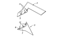
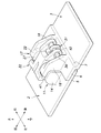
- separates and shows the 1st cowl and 2nd cowl which concern on embodiment The perspective view which isolate
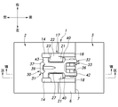
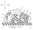
- a perspective view showing a temporary holding structure in the middle of forming a cowl fastening structure The perspective view which shows the state in the middle of changing from a temporary holding structure to a cowl fastening structure
- cowl fastening structure 1 is used for connecting the first cowl 2 and the second cowl 3.
- the coordinate axes shown in the drawings are used as a reference.
- FIG. 1 shows a side view of the first cowl 2 and the second cowl 3 covering the side of the front part of the motorcycle body as seen from the back side, that is, the side facing the vehicle side.
- Each of the first cowl 2 and the second cowl 3 is a resin injection-molded product, and is formed in a substantially plate shape.
- the first cowl 2 and the second cowl 3 may be formed of materials having different materials and colors.
- the edge 5 of the first cowl 2 and the edge 6 of the second cowl 3 are formed in complementary contours so as to overlap each other in the thickness direction. As shown in FIG. 2, the edge portion 6 of the second cowl 3 is provided so as to be displaced to the back side with respect to the other portions of the second cowl 3 via the stepped portion 7.
- the edge 6 of the second cowl 3 is disposed so as to overlap the back side of the edge 5 of the first cowl 2, and the first cowl 2 and The surfaces of the second cowl 3 are substantially flush with each other.
- first fastening seats 11 are provided on the back surface of the first cowl 2 and on the portion located inside the edge portion 5.
- second fastening seats 12 on the edge 6 on the back surface of the second cowl 3 and corresponding to the first fastening seat 11 when the second cowl 3 is connected to the first cowl 2. In the embodiment, three) are provided.
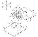
- the first fastening seat 11 protrudes upward from the back surface of the first cowl 2 substantially vertically and extends in the left-right direction, and both left and right ends of the first wall 13.
- a pair of guide walls 14 projecting on the back surface of the first cowl 2 so as to be orthogonal to the first wall 13 and extend forward, and has a substantially U-shape in plan view.
- a first through hole 15 having a substantially square cross section is formed in the lower portion of the first wall 13. In other words, the first through hole 15 is defined between the first cowl 2 and the back surface of the first cowl 2 by the first beam 16 extending in the left-right direction spanned between the pair of guide walls 14.
- the second fastening seat 12 has a hook 17 protruding from the edge of the edge 6 and a pair of reinforcing walls 18 extending rearward from the left and right sides of the hook 17.
- the hook 17 extends in the left-right direction along the edge of the edge 6 and protrudes upward substantially perpendicularly to the edge 6, and the second end from the upper end of the second wall base 21.
- a second wall intermediate portion 22 that extends substantially perpendicular to the wall base 21 and outward (forward) of the edge portion 6, and downwards substantially perpendicularly from a protruding end (front end) of the second wall intermediate portion 22. It has the 2nd wall front-end
- tip part 23 which extends and opposes the 2nd wall base 21 substantially parallel.
- the hook 17 is formed in a substantially U shape that opens downward, and is connected to the edge of the edge 6 at one end.
- the second wall middle part 22, and the second wall tip part 23 At the central part in the left-right direction of the second wall base 21, the second wall middle part 22, and the second wall tip part 23, one continuous long hole-like opening 25 is formed that penetrates each part in the thickness direction. Yes.
- the opening 25 includes a second through hole 26 and 26 that penetrate the second wall base 21 and the second wall tip 23 in the front-rear direction, and the second wall base so as to continue the two second through holes 26 and 26. 21, the second wall intermediate portion 22, and the second wall tip portion 23 can be divided into a connecting hole 27 portion which is a long hole-like through hole formed.
- the opening 25 divides the second wall base 21, the second wall middle portion 22, and the second wall tip 23 into a left side portion and a right side portion, and in the left-right direction at the protruding end portion of the second wall tip portion 23.
- a second beam 28 extending in the direction is formed.
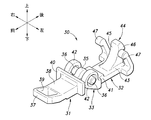
- FIG. 3 shows a clip 30 for fastening the first fastening seat 11 and the second fastening seat 12.
- the clip 30 has a structure in which a first member 31 and a second member 32, which are resin injection-molded products, are rotatably connected to each other via a hinge portion 33.
- the first member 31 extends in the front-rear direction, and a base end portion (rear end portion) 35 is formed narrow in the left-right direction.
- the base end portion 35 is formed with a pair of hinge shafts 36 protruding leftward or rightward.
- the pair of hinge shafts 36 are formed in a cylindrical shape having an axis extending in the left-right direction, and are coaxial with each other.
- the front end portion (front end portion) 37 and the intermediate portion 38 of the first member 31 are formed in a plate piece (strip shape) whose main surface is generally directed in the vertical direction.
- the front end portion 37 is formed with a locking hole 39 penetrating in the vertical direction.
- a regulating wall 40 protruding upward and left and right is formed.
- the second member 32 When the second member 32 is described with reference to the state shown in FIG. 3, the second member 32 has a pair of bearing portions 42 that extend in the front-rear direction and receive a pair of hinge shafts 36 at their base end portions 41 to be rotatable. ing. Accordingly, the second member 32 is rotatably connected to the first member 31 via the hinge portion 33 configured by the pair of hinge shafts 36 and the pair of bearing portions 42. Further, the bearing portion 42 is continuous with the base end portion 41 at the outer peripheral portion so that the center of the bearing portion 42 is disposed at a position displaced from a line obtained by extrapolating the center line of the second member 32.
- the distal end portion 43 of the second member 32 is widened in the left-right direction, and a locking portion protruding in a direction perpendicular to the extending direction of the second member 32 (upward in the drawing) is provided at an intermediate portion in the left-right direction.
- a nail 44 is formed.
- the locking claw 44 protrudes in a direction perpendicular to the protruding direction of the cantilever piece 45 from the tip of the cantilever piece 45, and protrudes upward from the tip of the cantilever piece 45. It is comprised from the nail
- the left and right side portions of the tip portion 43 where the locking claws 44 project are inclined toward the direction (upward) orthogonal to the extending direction of the second member 32 and toward the base end portion 41 (forward). Projecting flexible leaf spring pieces 47 are provided. Each leaf spring piece 47 is provided via the locking claw 44 and a predetermined gap in the left-right direction.
- Rotating the second member 32 with respect to the first member 31 causes the locking claw 44 to enter the locking hole 39.
- the cantilever part 45 of the locking claw 44 is bent, and the claw part 46 passes through the locking hole 39 and engages with the hole edge of the locking hole 39.
- the ring structure by the 1st member 31 and the 2nd member 32 is formed.
- the pair of leaf spring pieces 47 are disposed on the left and right outer sides of the distal end portion 37 of the first member 31.
- the fastening procedure includes a first stage in which the first fastening seat 11 and the second fastening seat 12 are engaged to form a temporary fastening structure, and a second structure in which the clip 30 is combined with the temporary fastening structure to form the cowl fastening structure 1. It can be roughly divided into stages.
- the temporary holding structure is formed by hooking the hook 17 of the second fastening seat 12 to the first wall 13 of the first fastening seat 11.
- the hook 17 is hooked on the first wall 13
- the front and rear end surfaces of the second wall tip 23 of the hook 17 are guided by sliding contact with the pair of guide walls 14, and are arranged at predetermined positions with respect to the first wall 13. Is done.
- the edge 6 of the second cowl 3 overlaps the back side of the edge 5 of the first cowl 2.
- the second wall tip 23 is fitted between the pair of guide walls 14 without rattling in the left-right direction.
- the distance between the pair of guide walls 14 and the width in the left-right direction of the second wall tip 23 may be set.
- the first wall 13 is disposed in the front-rear direction between the second wall base 21 and the second wall tip 23.
- the length in the front-rear direction of the second wall intermediate portion 22 and the thickness in the front-rear direction of the first wall 13 may be set so as to fit without rattling.
- the second through hole 26 of the second wall base 21, the first through hole 15 of the first wall 13, and the second through hole 26 of the second wall tip 23 are viewed from the front-rear direction,
- One insertion hole 50 penetrating the hook 17 and the first wall 13 is formed in the front-rear direction.
- the first beam 16 is disposed in the opening 25 of the hook 17, the opening 25 is partitioned into the first beam 16, and one insertion hole 50 penetrating the hook 17 and the first wall 13 is formed in the front-rear direction.
- the tip 37 of the first member 31 of the clip 30 is inserted into the insertion hole 50 from the second wall base 21 side in order to form the cowl fastening structure 1 from the temporary holding structure.
- the insertion is completed when the restriction wall 40 of the first member 31 comes into contact with the second wall base 21.
- the tip portion 37 of the first member 31 passes through the insertion hole 50 and protrudes outward from the second wall tip portion 23.
- the locking hole 39 of the distal end portion 37 is located outside the second wall distal end portion 23 and is exposed to the outside.
- the second member 32 is rotated with respect to the first member 31 (see FIG. 5), and the second member 32 is disposed so as to straddle the first beam 16 (first wall 13) from the upper side.
- the pawl 44 is inserted into the locking hole 39 and engaged.
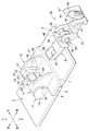
- FIGS. 6 to 9 the cowl fastening structure 1 in which the fastening operation is completed is formed.
- a ring structure is formed by the first member 31 and the second member 32, and the first beam 16 is arranged in the ring structure. Therefore, the clip 30 is kept engaged with the first beam 16.
- the first member 31 is inserted into the insertion hole 50, the relative displacement in the vertical and horizontal directions between the first wall 13 and the hook 17 is restricted. Therefore, the 1st fastening seat 11 and the 2nd fastening seat 12 are maintained in the state mutually engaged.
- the relative displacement in the vertical and horizontal directions between the first wall 13 and the hook 17 is restricted unless the first member 31 is broken, the structural strength of the cowl fastening structure 1 becomes relatively large. Further, as long as the cantilever 47 of the locking claw 44 is not broken or the locking hole 39 of the first member 31 is not broken, the clip 30 is prevented from coming out from the insertion hole 50.
- a part of the second member 32 is disposed in the connection hole 27 (opening 25) of the second wall intermediate portion 22, so the second member 32 does not protrude upward, and the cowl fastening structure 1 The size in the vertical direction is reduced.
- the leaf spring piece 47 abuts on the outer surface of the second wall tip 23, and the clip 30 including the second member 32 is inserted into the insertion hole 50 of the first member 31.
- the hook 17 is sandwiched between the leaf spring piece 47 and the restriction wall 40 in order to urge it in the insertion direction. Thereby, rattling with respect to the hook 17 of the clip 30 is suppressed.
- the connecting hole 27 may be omitted, and the second through hole 26 of the second wall base 21 and the second through hole 26 of the second wall tip 23 may be separated.
- the second member 32 may be shaped so as to straddle (turn around) the second wall intermediate portion 22.
- connection hole 27 is omitted so that the second through hole 26 does not communicate with the upper end surface of the second wall base 21, and the first member 31 is connected to the second through hole 26 of the second wall base 21 and the first through hole 26. It passes through the first through hole 15 of the wall 13. Further, it is preferable that the leaf spring piece 47 is in contact with the first wall 13 and the second wall base 21 and the first wall 13 are sandwiched between the regulation wall 40 and the leaf spring piece 47.
- a locking hole may be provided at the distal end portion 43 of the second member 32, and a locking claw that can be engaged with the locking hole may be provided at the distal end portion 37 of the first member 31.
- the locking claw may be formed in a shape that can pass through the insertion hole 50.
- the first member 31 is inserted into the insertion hole 50 from the second wall base 21 side, but may be inserted into the insertion hole 50 from the second wall tip 23 side.
- the cowl fastening structure 1 of the present invention can be used not only for fastening cowl members but also for fastening other members such as garnishes, trims, dashboards, and bumpers of automobiles.
Landscapes
- Engineering & Computer Science (AREA)
- Mechanical Engineering (AREA)
- Chemical & Material Sciences (AREA)
- Combustion & Propulsion (AREA)
- Transportation (AREA)
- Connection Of Plates (AREA)
- Superstructure Of Vehicle (AREA)
- Clamps And Clips (AREA)
- Body Structure For Vehicles (AREA)
Abstract
Description
Claims (6)
- 第1カウルと第2カウルとをクリップを用いて締結するカウル締結構造であって、
前記第1カウルには、第1貫通孔を有する第1壁が突設され、
前記第2カウルの縁部には、第2貫通孔を有する第2壁が突設され、
前記クリップは、それぞれの基端部同士がヒンジ部を介して互いに回動可能に連結された第1部材及び第2部材を備え、前記第1部材及び前記第2部材の一方の先端部には係止孔が形成され、前記第1部材及び前記第2部材の他方の先端部には前記係止孔に係合可能な係止爪が突設され、
前記第1貫通孔及び前記第2貫通孔が互いに対向するように、前記第1壁及び前記第2壁は対向して配置され、前記第1部材は、その前記先端部が前記第1貫通孔及び前記第2貫通孔を通過するように配置され、前記第2部材は前記第1壁及び前記第2壁を回り込み、前記第1部材及び前記第2部材の先端部同士が近接するように配置され、前記係止孔と前記係止爪とが係合することを特徴とするカウル締結構造。 - 前記係止孔は、前記第1部材に形成され、前記第1部材の前記第1貫通孔及び前記第2貫通孔への挿入方向と直交する軸線を有する貫通孔であり、
前記係止爪は、前記第2部材に形成され、前記係止孔を通過するとともに、前記係止孔の孔縁に引っ掛かって抜け止めがなされることを特徴とする請求項1に記載のカウル締結構造。 - 前記第2壁は、前記第1壁の表面に対向可能なように前記第2カウルの前記縁部に突設された第2壁基部と、前記第2壁基部の突出端から前記第1壁の突出端上を跨ぐように、前記第2壁基部と略垂直に突出した第2壁中間部と、前記第2壁中間部の突出端から前記第1壁の裏面に対向可能なように前記第2壁中間部と略垂直に突出した第2壁先端部とを有し、
前記第2壁基部及び前記第2壁先端部の前記第1貫通孔に対応する部分に、前記第2貫通孔がそれぞれ形成されていることを特徴とする請求項1又は請求項2に記載のカウル締結構造。 - 前記第2壁基部に形成された前記第2貫通孔と、前記第2壁先端部に形成された前記第2貫通孔とは、前記第2壁基部、前記第2壁中間部及び前記第2壁先端部に延在する連結孔を介して連結されており、
前記係止孔と前記係止爪とが係合した状態で、前記第2部材の一部は前記連結孔内に配置されることを特徴とする請求項3に記載のカウル締結構造。 - 前記第1部材には、前記第2壁基部に当接して、前記第1部材の前記第1貫通孔及び前記第2貫通孔に対する挿入長さを規定する規制壁が突設され、
前記第2部材の先端部には、前記第2壁先端部に当接し、前記第1部材の前記第1貫通孔及び前記第2貫通孔への挿入方向に前記第2部材を付勢する板ばね片が突設されていることを特徴とする請求項3又は請求項4に記載のカウル締結構造。 - 前記第1カウルには、前記第2壁先端部に摺接し、前記第2壁先端部の前記第1壁に対する位置を規制するガイド壁が突設されていることを特徴とする請求項3~請求項5のいずれか1つの項に記載のカウル締結構造。
Priority Applications (2)
| Application Number | Priority Date | Filing Date | Title |
|---|---|---|---|
| US14/119,238 US9004568B2 (en) | 2011-05-27 | 2012-05-17 | Cowling fastening structure |
| BR112013030388A BR112013030388B8 (pt) | 2011-05-27 | 2012-05-17 | Estrutura de fixação de capô |
Applications Claiming Priority (2)
| Application Number | Priority Date | Filing Date | Title |
|---|---|---|---|
| JP2011119127A JP5730129B2 (ja) | 2011-05-27 | 2011-05-27 | カウル締結構造 |
| JP2011-119127 | 2011-05-27 |
Publications (1)
| Publication Number | Publication Date |
|---|---|
| WO2012164852A1 true WO2012164852A1 (ja) | 2012-12-06 |
Family
ID=47258729
Family Applications (1)
| Application Number | Title | Priority Date | Filing Date |
|---|---|---|---|
| PCT/JP2012/003219 WO2012164852A1 (ja) | 2011-05-27 | 2012-05-17 | カウル締結構造 |
Country Status (4)
| Country | Link |
|---|---|
| US (1) | US9004568B2 (ja) |
| JP (1) | JP5730129B2 (ja) |
| BR (1) | BR112013030388B8 (ja) |
| WO (1) | WO2012164852A1 (ja) |
Families Citing this family (3)
| Publication number | Priority date | Publication date | Assignee | Title |
|---|---|---|---|---|
| JP5864392B2 (ja) * | 2012-09-28 | 2016-02-17 | 本田技研工業株式会社 | 車両部品の連結構造 |
| DE102016201521A1 (de) * | 2016-02-02 | 2017-08-03 | Bayerische Motoren Werke Aktiengesellschaft | Verkleidungsanordnung für ein Kraftfahrzeug |
| CN109131661B (zh) * | 2018-07-28 | 2023-08-29 | 重庆隆鑫机车有限公司 | 摩托车仪表安装结构及其摩托车 |
Citations (3)
| Publication number | Priority date | Publication date | Assignee | Title |
|---|---|---|---|---|
| JPS5488478U (ja) * | 1977-12-07 | 1979-06-22 | ||
| JPS6247486U (ja) * | 1985-09-13 | 1987-03-24 | ||
| JP2007530355A (ja) * | 2004-03-31 | 2007-11-01 | バイエリッシェ モートーレン ウエルケ アクチエンゲゼルシャフト | オートバイフェアリング |
Family Cites Families (12)
| Publication number | Priority date | Publication date | Assignee | Title |
|---|---|---|---|---|
| FR2507707B1 (fr) * | 1981-06-12 | 1985-09-06 | Chausson Usines Sa | Dispositif pour l'assemblage mutuel de deux pieces devant etre demontees de facon occasionnelle |
| FR2820391B1 (fr) * | 2001-02-05 | 2003-04-11 | Plastic Omnium Cie | Ensemble de deux pieces de carrosserie en matiere plastique a reunir bord a bord |
| US6499783B1 (en) * | 2001-10-09 | 2002-12-31 | Delores J. Husted | Convertible flatbed utility stock trailer |
| US20030070390A1 (en) * | 2001-10-11 | 2003-04-17 | Dunn J. Paul | Interconnected trim components with light-blocking overlap flanges |
| JP4031974B2 (ja) * | 2002-07-15 | 2008-01-09 | 本田技研工業株式会社 | 自動二輪車のシート取付構造 |
| JP4659011B2 (ja) * | 2002-07-15 | 2011-03-30 | 本田技研工業株式会社 | 自動二輪車のシート取付構造 |
| JP5002492B2 (ja) * | 2008-02-28 | 2012-08-15 | 本田技研工業株式会社 | 車両の燃料フィルタの取付構造 |
| US8070213B2 (en) * | 2008-06-06 | 2011-12-06 | Caterpillar Inc. | Machine having trim piece assembly with reduced discordance and method |
| JP5254164B2 (ja) * | 2009-09-15 | 2013-08-07 | 本田技研工業株式会社 | 電動二輪車 |
| CN102656375B (zh) * | 2009-11-30 | 2014-06-25 | 大和化成工业株式会社 | 夹子 |
| US9121426B2 (en) * | 2010-11-09 | 2015-09-01 | Illinois Tool Works Inc. | Bracket clip |
| JP5764522B2 (ja) * | 2012-04-26 | 2015-08-19 | 本田技研工業株式会社 | クリップ |
-
2011
- 2011-05-27 JP JP2011119127A patent/JP5730129B2/ja active Active
-
2012
- 2012-05-17 BR BR112013030388A patent/BR112013030388B8/pt active IP Right Grant
- 2012-05-17 US US14/119,238 patent/US9004568B2/en active Active
- 2012-05-17 WO PCT/JP2012/003219 patent/WO2012164852A1/ja active Application Filing
Patent Citations (3)
| Publication number | Priority date | Publication date | Assignee | Title |
|---|---|---|---|---|
| JPS5488478U (ja) * | 1977-12-07 | 1979-06-22 | ||
| JPS6247486U (ja) * | 1985-09-13 | 1987-03-24 | ||
| JP2007530355A (ja) * | 2004-03-31 | 2007-11-01 | バイエリッシェ モートーレン ウエルケ アクチエンゲゼルシャフト | オートバイフェアリング |
Also Published As
| Publication number | Publication date |
|---|---|
| BR112013030388B8 (pt) | 2022-09-06 |
| JP5730129B2 (ja) | 2015-06-03 |
| US9004568B2 (en) | 2015-04-14 |
| BR112013030388A2 (pt) | 2016-12-13 |
| JP2012245883A (ja) | 2012-12-13 |
| BR112013030388B1 (pt) | 2020-10-27 |
| US20140091597A1 (en) | 2014-04-03 |
Similar Documents
| Publication | Publication Date | Title |
|---|---|---|
| JP4832480B2 (ja) | 燃料タンクの保護板取付構造 | |
| JP2014094722A (ja) | 収納ボックス | |
| JP4345981B2 (ja) | 一方の面を製品表面とした合成樹脂製品の連結構造 | |
| JP3721185B2 (ja) | 射出成形品及びその用途 | |
| JP5860981B1 (ja) | バックル装置 | |
| JP6136867B2 (ja) | 加飾部品 | |
| JP2012215055A (ja) | 車両用リッドロック装置 | |
| US8393683B2 (en) | Automotive seat headrest supporting apparatus | |
| WO2012164852A1 (ja) | カウル締結構造 | |
| JP6706864B2 (ja) | 回転コネクタおよび回転コネクタの固定構造 | |
| JP6419537B2 (ja) | 車両用シート | |
| JP4936317B2 (ja) | 合成樹脂成形品のヒンジ部の構造 | |
| KR101181574B1 (ko) | 부착구 | |
| JP6023886B2 (ja) | シートベルトアジャスタ構造 | |
| WO2012035860A1 (ja) | バックル及びシートベルト装置 | |
| JP6177823B2 (ja) | バックル装置 | |
| JP6387840B2 (ja) | 乗物用シート | |
| JP2013133876A (ja) | 部材連結構造 | |
| JP7120986B2 (ja) | 外装部材の接続構造 | |
| JP5176926B2 (ja) | 車両用フロントコンソールモジュールの組付構造 | |
| JP5312253B2 (ja) | クリップ及びクリップ付きワイヤハーネス | |
| TW201704060A (zh) | 帶子引導部 | |
| JP2010095117A (ja) | 車両用内装部品の組付け構造 | |
| JP7415959B2 (ja) | クリップ | |
| JP5331612B2 (ja) | 金属クリップの取付構造 |
Legal Events
| Date | Code | Title | Description |
|---|---|---|---|
| 121 | Ep: the epo has been informed by wipo that ep was designated in this application |
Ref document number: 12793254 Country of ref document: EP Kind code of ref document: A1 |
|
| WWE | Wipo information: entry into national phase |
Ref document number: 14119238 Country of ref document: US |
|
| NENP | Non-entry into the national phase |
Ref country code: DE |
|
| REG | Reference to national code |
Ref country code: BR Ref legal event code: B01A Ref document number: 112013030388 Country of ref document: BR |
|
| 122 | Ep: pct application non-entry in european phase |
Ref document number: 12793254 Country of ref document: EP Kind code of ref document: A1 |
|
| ENP | Entry into the national phase |
Ref document number: 112013030388 Country of ref document: BR Kind code of ref document: A2 Effective date: 20131126 |