WO2012164743A1 - 車両、電気機器および電力送受電システム - Google Patents
車両、電気機器および電力送受電システム Download PDFInfo
- Publication number
- WO2012164743A1 WO2012164743A1 PCT/JP2011/062817 JP2011062817W WO2012164743A1 WO 2012164743 A1 WO2012164743 A1 WO 2012164743A1 JP 2011062817 W JP2011062817 W JP 2011062817W WO 2012164743 A1 WO2012164743 A1 WO 2012164743A1
- Authority
- WO
- WIPO (PCT)
- Prior art keywords
- power
- vehicle
- frequency
- electromagnetic field
- resonance
- Prior art date
Links
Images


Classifications
-
- B—PERFORMING OPERATIONS; TRANSPORTING
- B60—VEHICLES IN GENERAL
- B60L—PROPULSION OF ELECTRICALLY-PROPELLED VEHICLES; SUPPLYING ELECTRIC POWER FOR AUXILIARY EQUIPMENT OF ELECTRICALLY-PROPELLED VEHICLES; ELECTRODYNAMIC BRAKE SYSTEMS FOR VEHICLES IN GENERAL; MAGNETIC SUSPENSION OR LEVITATION FOR VEHICLES; MONITORING OPERATING VARIABLES OF ELECTRICALLY-PROPELLED VEHICLES; ELECTRIC SAFETY DEVICES FOR ELECTRICALLY-PROPELLED VEHICLES
- B60L53/00—Methods of charging batteries, specially adapted for electric vehicles; Charging stations or on-board charging equipment therefor; Exchange of energy storage elements in electric vehicles
- B60L53/10—Methods of charging batteries, specially adapted for electric vehicles; Charging stations or on-board charging equipment therefor; Exchange of energy storage elements in electric vehicles characterised by the energy transfer between the charging station and the vehicle
- B60L53/12—Inductive energy transfer
-
- B—PERFORMING OPERATIONS; TRANSPORTING
- B60—VEHICLES IN GENERAL
- B60L—PROPULSION OF ELECTRICALLY-PROPELLED VEHICLES; SUPPLYING ELECTRIC POWER FOR AUXILIARY EQUIPMENT OF ELECTRICALLY-PROPELLED VEHICLES; ELECTRODYNAMIC BRAKE SYSTEMS FOR VEHICLES IN GENERAL; MAGNETIC SUSPENSION OR LEVITATION FOR VEHICLES; MONITORING OPERATING VARIABLES OF ELECTRICALLY-PROPELLED VEHICLES; ELECTRIC SAFETY DEVICES FOR ELECTRICALLY-PROPELLED VEHICLES
- B60L1/00—Supplying electric power to auxiliary equipment of vehicles
- B60L1/006—Supplying electric power to auxiliary equipment of vehicles to power outlets
-
- B—PERFORMING OPERATIONS; TRANSPORTING
- B60—VEHICLES IN GENERAL
- B60L—PROPULSION OF ELECTRICALLY-PROPELLED VEHICLES; SUPPLYING ELECTRIC POWER FOR AUXILIARY EQUIPMENT OF ELECTRICALLY-PROPELLED VEHICLES; ELECTRODYNAMIC BRAKE SYSTEMS FOR VEHICLES IN GENERAL; MAGNETIC SUSPENSION OR LEVITATION FOR VEHICLES; MONITORING OPERATING VARIABLES OF ELECTRICALLY-PROPELLED VEHICLES; ELECTRIC SAFETY DEVICES FOR ELECTRICALLY-PROPELLED VEHICLES
- B60L53/00—Methods of charging batteries, specially adapted for electric vehicles; Charging stations or on-board charging equipment therefor; Exchange of energy storage elements in electric vehicles
- B60L53/10—Methods of charging batteries, specially adapted for electric vehicles; Charging stations or on-board charging equipment therefor; Exchange of energy storage elements in electric vehicles characterised by the energy transfer between the charging station and the vehicle
- B60L53/12—Inductive energy transfer
- B60L53/122—Circuits or methods for driving the primary coil, e.g. supplying electric power to the coil
-
- B—PERFORMING OPERATIONS; TRANSPORTING
- B60—VEHICLES IN GENERAL
- B60L—PROPULSION OF ELECTRICALLY-PROPELLED VEHICLES; SUPPLYING ELECTRIC POWER FOR AUXILIARY EQUIPMENT OF ELECTRICALLY-PROPELLED VEHICLES; ELECTRODYNAMIC BRAKE SYSTEMS FOR VEHICLES IN GENERAL; MAGNETIC SUSPENSION OR LEVITATION FOR VEHICLES; MONITORING OPERATING VARIABLES OF ELECTRICALLY-PROPELLED VEHICLES; ELECTRIC SAFETY DEVICES FOR ELECTRICALLY-PROPELLED VEHICLES
- B60L53/00—Methods of charging batteries, specially adapted for electric vehicles; Charging stations or on-board charging equipment therefor; Exchange of energy storage elements in electric vehicles
- B60L53/10—Methods of charging batteries, specially adapted for electric vehicles; Charging stations or on-board charging equipment therefor; Exchange of energy storage elements in electric vehicles characterised by the energy transfer between the charging station and the vehicle
- B60L53/12—Inductive energy transfer
- B60L53/126—Methods for pairing a vehicle and a charging station, e.g. establishing a one-to-one relation between a wireless power transmitter and a wireless power receiver
-
- B—PERFORMING OPERATIONS; TRANSPORTING
- B60—VEHICLES IN GENERAL
- B60L—PROPULSION OF ELECTRICALLY-PROPELLED VEHICLES; SUPPLYING ELECTRIC POWER FOR AUXILIARY EQUIPMENT OF ELECTRICALLY-PROPELLED VEHICLES; ELECTRODYNAMIC BRAKE SYSTEMS FOR VEHICLES IN GENERAL; MAGNETIC SUSPENSION OR LEVITATION FOR VEHICLES; MONITORING OPERATING VARIABLES OF ELECTRICALLY-PROPELLED VEHICLES; ELECTRIC SAFETY DEVICES FOR ELECTRICALLY-PROPELLED VEHICLES
- B60L53/00—Methods of charging batteries, specially adapted for electric vehicles; Charging stations or on-board charging equipment therefor; Exchange of energy storage elements in electric vehicles
- B60L53/30—Constructional details of charging stations
- B60L53/35—Means for automatic or assisted adjustment of the relative position of charging devices and vehicles
- B60L53/36—Means for automatic or assisted adjustment of the relative position of charging devices and vehicles by positioning the vehicle
-
- H—ELECTRICITY
- H02—GENERATION; CONVERSION OR DISTRIBUTION OF ELECTRIC POWER
- H02J—CIRCUIT ARRANGEMENTS OR SYSTEMS FOR SUPPLYING OR DISTRIBUTING ELECTRIC POWER; SYSTEMS FOR STORING ELECTRIC ENERGY
- H02J50/00—Circuit arrangements or systems for wireless supply or distribution of electric power
- H02J50/10—Circuit arrangements or systems for wireless supply or distribution of electric power using inductive coupling
- H02J50/12—Circuit arrangements or systems for wireless supply or distribution of electric power using inductive coupling of the resonant type
-
- H—ELECTRICITY
- H02—GENERATION; CONVERSION OR DISTRIBUTION OF ELECTRIC POWER
- H02J—CIRCUIT ARRANGEMENTS OR SYSTEMS FOR SUPPLYING OR DISTRIBUTING ELECTRIC POWER; SYSTEMS FOR STORING ELECTRIC ENERGY
- H02J50/00—Circuit arrangements or systems for wireless supply or distribution of electric power
- H02J50/50—Circuit arrangements or systems for wireless supply or distribution of electric power using additional energy repeaters between transmitting devices and receiving devices
- H02J50/502—Circuit arrangements or systems for wireless supply or distribution of electric power using additional energy repeaters between transmitting devices and receiving devices the energy repeater being integrated together with the emitter or the receiver
-
- H—ELECTRICITY
- H02—GENERATION; CONVERSION OR DISTRIBUTION OF ELECTRIC POWER
- H02J—CIRCUIT ARRANGEMENTS OR SYSTEMS FOR SUPPLYING OR DISTRIBUTING ELECTRIC POWER; SYSTEMS FOR STORING ELECTRIC ENERGY
- H02J50/00—Circuit arrangements or systems for wireless supply or distribution of electric power
- H02J50/80—Circuit arrangements or systems for wireless supply or distribution of electric power involving the exchange of data, concerning supply or distribution of electric power, between transmitting devices and receiving devices
-
- B—PERFORMING OPERATIONS; TRANSPORTING
- B60—VEHICLES IN GENERAL
- B60L—PROPULSION OF ELECTRICALLY-PROPELLED VEHICLES; SUPPLYING ELECTRIC POWER FOR AUXILIARY EQUIPMENT OF ELECTRICALLY-PROPELLED VEHICLES; ELECTRODYNAMIC BRAKE SYSTEMS FOR VEHICLES IN GENERAL; MAGNETIC SUSPENSION OR LEVITATION FOR VEHICLES; MONITORING OPERATING VARIABLES OF ELECTRICALLY-PROPELLED VEHICLES; ELECTRIC SAFETY DEVICES FOR ELECTRICALLY-PROPELLED VEHICLES
- B60L2210/00—Converter types
- B60L2210/30—AC to DC converters
-
- B—PERFORMING OPERATIONS; TRANSPORTING
- B60—VEHICLES IN GENERAL
- B60L—PROPULSION OF ELECTRICALLY-PROPELLED VEHICLES; SUPPLYING ELECTRIC POWER FOR AUXILIARY EQUIPMENT OF ELECTRICALLY-PROPELLED VEHICLES; ELECTRODYNAMIC BRAKE SYSTEMS FOR VEHICLES IN GENERAL; MAGNETIC SUSPENSION OR LEVITATION FOR VEHICLES; MONITORING OPERATING VARIABLES OF ELECTRICALLY-PROPELLED VEHICLES; ELECTRIC SAFETY DEVICES FOR ELECTRICALLY-PROPELLED VEHICLES
- B60L2210/00—Converter types
- B60L2210/40—DC to AC converters
-
- B—PERFORMING OPERATIONS; TRANSPORTING
- B60—VEHICLES IN GENERAL
- B60Y—INDEXING SCHEME RELATING TO ASPECTS CROSS-CUTTING VEHICLE TECHNOLOGY
- B60Y2200/00—Type of vehicle
- B60Y2200/90—Vehicles comprising electric prime movers
- B60Y2200/91—Electric vehicles
-
- B—PERFORMING OPERATIONS; TRANSPORTING
- B60—VEHICLES IN GENERAL
- B60Y—INDEXING SCHEME RELATING TO ASPECTS CROSS-CUTTING VEHICLE TECHNOLOGY
- B60Y2200/00—Type of vehicle
- B60Y2200/90—Vehicles comprising electric prime movers
- B60Y2200/92—Hybrid vehicles
-
- H—ELECTRICITY
- H02—GENERATION; CONVERSION OR DISTRIBUTION OF ELECTRIC POWER
- H02J—CIRCUIT ARRANGEMENTS OR SYSTEMS FOR SUPPLYING OR DISTRIBUTING ELECTRIC POWER; SYSTEMS FOR STORING ELECTRIC ENERGY
- H02J7/00—Circuit arrangements for charging or depolarising batteries or for supplying loads from batteries
- H02J7/00032—Circuit arrangements for charging or depolarising batteries or for supplying loads from batteries characterised by data exchange
- H02J7/00034—Charger exchanging data with an electronic device, i.e. telephone, whose internal battery is under charge
-
- Y—GENERAL TAGGING OF NEW TECHNOLOGICAL DEVELOPMENTS; GENERAL TAGGING OF CROSS-SECTIONAL TECHNOLOGIES SPANNING OVER SEVERAL SECTIONS OF THE IPC; TECHNICAL SUBJECTS COVERED BY FORMER USPC CROSS-REFERENCE ART COLLECTIONS [XRACs] AND DIGESTS
- Y02—TECHNOLOGIES OR APPLICATIONS FOR MITIGATION OR ADAPTATION AGAINST CLIMATE CHANGE
- Y02T—CLIMATE CHANGE MITIGATION TECHNOLOGIES RELATED TO TRANSPORTATION
- Y02T10/00—Road transport of goods or passengers
- Y02T10/60—Other road transportation technologies with climate change mitigation effect
- Y02T10/70—Energy storage systems for electromobility, e.g. batteries
-
- Y—GENERAL TAGGING OF NEW TECHNOLOGICAL DEVELOPMENTS; GENERAL TAGGING OF CROSS-SECTIONAL TECHNOLOGIES SPANNING OVER SEVERAL SECTIONS OF THE IPC; TECHNICAL SUBJECTS COVERED BY FORMER USPC CROSS-REFERENCE ART COLLECTIONS [XRACs] AND DIGESTS
- Y02—TECHNOLOGIES OR APPLICATIONS FOR MITIGATION OR ADAPTATION AGAINST CLIMATE CHANGE
- Y02T—CLIMATE CHANGE MITIGATION TECHNOLOGIES RELATED TO TRANSPORTATION
- Y02T10/00—Road transport of goods or passengers
- Y02T10/60—Other road transportation technologies with climate change mitigation effect
- Y02T10/7072—Electromobility specific charging systems or methods for batteries, ultracapacitors, supercapacitors or double-layer capacitors
-
- Y—GENERAL TAGGING OF NEW TECHNOLOGICAL DEVELOPMENTS; GENERAL TAGGING OF CROSS-SECTIONAL TECHNOLOGIES SPANNING OVER SEVERAL SECTIONS OF THE IPC; TECHNICAL SUBJECTS COVERED BY FORMER USPC CROSS-REFERENCE ART COLLECTIONS [XRACs] AND DIGESTS
- Y02—TECHNOLOGIES OR APPLICATIONS FOR MITIGATION OR ADAPTATION AGAINST CLIMATE CHANGE
- Y02T—CLIMATE CHANGE MITIGATION TECHNOLOGIES RELATED TO TRANSPORTATION
- Y02T10/00—Road transport of goods or passengers
- Y02T10/60—Other road transportation technologies with climate change mitigation effect
- Y02T10/72—Electric energy management in electromobility
-
- Y—GENERAL TAGGING OF NEW TECHNOLOGICAL DEVELOPMENTS; GENERAL TAGGING OF CROSS-SECTIONAL TECHNOLOGIES SPANNING OVER SEVERAL SECTIONS OF THE IPC; TECHNICAL SUBJECTS COVERED BY FORMER USPC CROSS-REFERENCE ART COLLECTIONS [XRACs] AND DIGESTS
- Y02—TECHNOLOGIES OR APPLICATIONS FOR MITIGATION OR ADAPTATION AGAINST CLIMATE CHANGE
- Y02T—CLIMATE CHANGE MITIGATION TECHNOLOGIES RELATED TO TRANSPORTATION
- Y02T90/00—Enabling technologies or technologies with a potential or indirect contribution to GHG emissions mitigation
- Y02T90/10—Technologies relating to charging of electric vehicles
- Y02T90/12—Electric charging stations
-
- Y—GENERAL TAGGING OF NEW TECHNOLOGICAL DEVELOPMENTS; GENERAL TAGGING OF CROSS-SECTIONAL TECHNOLOGIES SPANNING OVER SEVERAL SECTIONS OF THE IPC; TECHNICAL SUBJECTS COVERED BY FORMER USPC CROSS-REFERENCE ART COLLECTIONS [XRACs] AND DIGESTS
- Y02—TECHNOLOGIES OR APPLICATIONS FOR MITIGATION OR ADAPTATION AGAINST CLIMATE CHANGE
- Y02T—CLIMATE CHANGE MITIGATION TECHNOLOGIES RELATED TO TRANSPORTATION
- Y02T90/00—Enabling technologies or technologies with a potential or indirect contribution to GHG emissions mitigation
- Y02T90/10—Technologies relating to charging of electric vehicles
- Y02T90/14—Plug-in electric vehicles
-
- Y—GENERAL TAGGING OF NEW TECHNOLOGICAL DEVELOPMENTS; GENERAL TAGGING OF CROSS-SECTIONAL TECHNOLOGIES SPANNING OVER SEVERAL SECTIONS OF THE IPC; TECHNICAL SUBJECTS COVERED BY FORMER USPC CROSS-REFERENCE ART COLLECTIONS [XRACs] AND DIGESTS
- Y02—TECHNOLOGIES OR APPLICATIONS FOR MITIGATION OR ADAPTATION AGAINST CLIMATE CHANGE
- Y02T—CLIMATE CHANGE MITIGATION TECHNOLOGIES RELATED TO TRANSPORTATION
- Y02T90/00—Enabling technologies or technologies with a potential or indirect contribution to GHG emissions mitigation
- Y02T90/10—Technologies relating to charging of electric vehicles
- Y02T90/16—Information or communication technologies improving the operation of electric vehicles
Definitions
- the present invention relates to a vehicle, an electric device, and a power transmission / reception system, and more particularly to a vehicle, an electric device, and a power transmission / reception system that perform power transmission / reception in a contactless manner.
- Vehicles configured to be able to charge an in-vehicle power storage device from the outside, such as electric vehicles and plug-in hybrid vehicles, have been put into practical use. Techniques for automatically charging and for that purpose guiding the parking position are also being studied. In addition, there is a need for powering in-vehicle electric devices in the vehicle for charging a battery of a portable phone.
- Patent Document 1 discloses a charging device for charging a battery of a mobile phone by electromagnetic induction in a vehicle.
- JP 2007-104868 A Japanese Patent Laid-Open No. 2005-110412 International Publication No. 2010/052785 Pamphlet
- An object of the present invention is to provide a vehicle, an electric device, and an electric power transmission device that can receive electric power for traveling of the vehicle from outside without contact and can transmit electric power supplied to the in-vehicle electric device without contact. It is to provide a power receiving system.
- the present invention relates to a vehicle, and a power receiving device that receives electric power for driving the vehicle in a non-contact manner through electromagnetic resonance, and a power that is supplied to an electric device inside the vehicle in a non-contact manner through electromagnetic resonance.
- Power transmission device for transmitting power.
- the frequency of the electromagnetic field used by the power receiving device for power reception is set to be different from the frequency of the electromagnetic field used for power transmission by the power transmission device.
- the frequency of the electromagnetic field used for power reception by the power receiving device and the frequency of the power transmission device used for power transmission are set so that the frequency of the electromagnetic field used for power reception by the power receiving device is lower than the frequency of the electromagnetic field used by the power transmission device for power transmission.
- the frequency of the electromagnetic field to be used is set.
- the power that the power receiving device receives in a contactless manner from an external power transmission device installed outside the vehicle is greater than the power that the power transmitting device transmits in a contactless manner to an electrical device.
- the vehicle further includes a drive device for driving the vehicle, a main battery for supplying electric power to the drive device, and an auxiliary battery provided separately from the main battery.
- the voltage of the auxiliary battery is lower than the voltage of the main battery, and the power transmission device receives power from the auxiliary battery and transmits power to the electrical equipment.
- the vehicle further includes a control unit that sets the operation state of the vehicle to a travelable state and a travel-impossible state in accordance with the operation of the occupant.
- the control unit permits charging of the main battery with the power received by the power receiving device in the travelable state, and permits the power supply from the power transmission device to the electrical device.
- the main battery is allowed to be charged with the electric power received by the apparatus, and the electric power is prohibited from being supplied from the power transmission apparatus to the electric device.
- the present invention is an electric device used inside a vehicle.
- the vehicle includes a power receiving device that receives electric power for traveling of the vehicle from an external power transmitting device in a contactless manner through electromagnetic resonance, and a power transmission device that transmits in a contactless manner the electric power supplied to the electrical equipment through electromagnetic resonance.
- the electric device includes a power reception unit that receives power transmitted from the power transmission device using a frequency of an electromagnetic field different from the frequency of the electromagnetic field used by the vehicle power reception device for power reception.
- the power reception unit receives electric power transmitted from the power transmission device using an electromagnetic field frequency higher than an electromagnetic field frequency used by the vehicle power reception device for power reception.
- the present invention is a power transmission / reception system, a vehicle, an external power transmission device that transmits power to the vehicle in a contactless manner by electromagnetic resonance, and an electric device that can be used inside the vehicle.
- the vehicle includes a power receiving device that receives electric power for traveling of the vehicle from an external power transmitting device in a contactless manner through electromagnetic resonance, and a power transmission device that transmits in a contactless manner the electric power supplied to the electrical equipment through electromagnetic resonance.
- the frequency of the electromagnetic field used by the power receiving device for power reception is set to be different from the frequency of the electromagnetic field used for power transmission by the power transmission device.
- the present invention it is possible to receive power for driving a vehicle in a contactless manner from the outside and to transmit power supplied to an in-vehicle electrical device in a contactless manner without affecting each other.
- FIG. 1 is an overall configuration diagram of a vehicle power supply system according to an embodiment of the present invention. It is a figure for demonstrating the principle of the power transmission by the resonance method. It is the figure which showed the relationship between the distance from an electric current source (magnetic current source), and the intensity
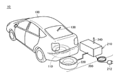
- FIG. 1 is an overall configuration diagram of a vehicle power supply system according to an embodiment of the present invention.
- power transmission / reception system 10 includes a vehicle 100 and a power feeding device 200.
- Vehicle 100 includes a power receiving unit 110 and a communication unit 130.
- the power receiving unit 110 is installed on the bottom surface of the vehicle body, and is configured to receive the power transmitted from the power transmitting unit 220 of the power supply apparatus 200 in a contactless manner.
- the power receiving unit 110 includes a self-resonant coil described later, and receives power from the power transmitting unit 220 in a non-contact manner by resonating with a self-resonant coil included in the power transmitting unit 220 via an electromagnetic field.
- Communication unit 130 is a communication interface for performing communication between vehicle 100 and power supply apparatus 200.
- the power feeding device 200 includes a high frequency power supply device 210, a power transmission unit 220, and a communication unit 240.
- the high frequency power supply device 210 converts commercial AC power supplied through, for example, the connector 212 into high frequency power and outputs the high frequency power to the power transmission unit 220.
- the frequency of the high frequency power generated by the high frequency power supply device 210 is, for example, 1 MHz to several tens of MHz.
- the power transmission unit 220 is installed on the floor of a parking lot, for example, and is configured to send the high frequency power supplied from the high frequency power supply device 210 to the power receiving unit 110 of the vehicle 100 in a non-contact manner.
- the power transmission unit 220 includes a self-resonant coil, and the self-resonant coil resonates with the self-resonant coil included in the power receiving unit 110 via an electromagnetic field to transmit power to the power receiving unit 110 in a contactless manner.
- Communication unit 240 is a communication interface for performing communication between power feeding apparatus 200 and vehicle 100.
- the vehicle 100 when power is supplied from the power supply apparatus 200 to the vehicle 100, it is necessary to guide the vehicle 100 to the power supply apparatus 200 and align the power receiving unit 110 of the vehicle 100 and the power transmission unit 220 of the power supply apparatus 200. That is, the vehicle 100 is not easily aligned unlike an in-vehicle electrical device described later.
- the user In an in-car electrical device, the user can easily lift the hand up and place it at an appropriate position of a power supply unit such as a charger.
- the vehicle needs to be operated by the user to stop the vehicle at an appropriate position, and cannot be lifted by hand to adjust the position.
- the power supply from the power supply apparatus 200 to the vehicle 100 has a large tolerance with respect to displacement.
- the transmission distance is short and it is said that the tolerance is small with respect to positional deviation.
- the electromagnetic induction method is used to supply power to the vehicle, the driver's high-precision driving technology is required, a high-accuracy vehicle guidance device must be installed in the vehicle, or even in rough parking positions. There is a possibility that a movable part that moves the coil position is necessary so that it can be handled.
- the resonance method using an electromagnetic field is capable of transmitting a relatively large amount of power even when the transmission distance is several meters, and is generally said to have a greater tolerance for positional deviation than the electromagnetic induction method. Therefore, in power transmission / reception system 10 according to this embodiment, power is supplied from power supply apparatus 200 to vehicle 100 using the resonance method.
- FIG. 2 is a diagram for explaining the principle of power transmission by the resonance method.
- this resonance method in the same way as two tuning forks resonate, two LC resonance coils having the same natural frequency resonate in an electromagnetic field (near field), and thereby, from one coil. Electric power is transmitted to the other coil via an electromagnetic field.
- the primary coil 320 is connected to the high frequency power source 310, and high frequency power of 1 M to several tens of MHz is supplied to the primary self-resonant coil 330 that is magnetically coupled to the primary coil 320 by electromagnetic induction.
- the primary self-resonant coil 330 is an LC resonator having an inductance and stray capacitance of the coil itself, and resonates with a secondary self-resonant coil 340 having the same resonance frequency as the primary self-resonant coil 330 via an electromagnetic field (near field). .
- energy electrical power moves from the primary self-resonant coil 330 to the secondary self-resonant coil 340 via the electromagnetic field.
- the energy (electric power) transferred to the secondary self-resonant coil 340 is taken out by the secondary coil 350 magnetically coupled to the secondary self-resonant coil 340 by electromagnetic induction and supplied to the load 360.
- power transmission by the resonance method is realized when the Q value indicating the resonance intensity between the primary self-resonant coil 330 and the secondary self-resonant coil 340 is greater than 100, for example.
- the secondary self-resonant coil 340 and the secondary coil 350 correspond to the power receiving unit 110 in FIG. 1
- the primary coil 320 and the primary self-resonant coil 330 correspond to the power transmission unit 220 in FIG. 1.
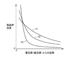
- FIG. 3 is a diagram showing the relationship between the distance from the current source (magnetic current source) and the intensity of the electromagnetic field.
- the electromagnetic field includes three components.
- the curve k1 is a component that is inversely proportional to the distance from the wave source, and is referred to as a “radiated electromagnetic field”.
- a curve k2 is a component inversely proportional to the square of the distance from the wave source, and is referred to as an “induction electromagnetic field”.
- the curve k3 is a component inversely proportional to the cube of the distance from the wave source, and is referred to as an “electrostatic magnetic field”.
- the resonance method energy (electric power) is transmitted using this near field (evanescent field). That is, by using a near field to resonate a pair of resonators (for example, a pair of LC resonance coils) having the same natural frequency, one resonator (primary self-resonant coil) and the other resonator (two Energy (electric power) is transmitted to the next self-resonant coil. Since this near field does not propagate energy (electric power) far away, the resonance method transmits power with less energy loss than electromagnetic waves that transmit energy (electric power) by "radiation electromagnetic field” that propagates energy far away. be able to.
- FIG. 4 is a diagram for explaining the distance between the power reception unit 110 and the power transmission unit 220.
- the distance D1 between the power reception unit 110 and the power transmission unit 220 is a distance larger than the transmission distance of the electromagnetic induction method.
- This distance D1 is also a distance that enables power transmission by the resonance method.
- the distance D1 can be changed by changing the shapes and sizes of the self-resonant coils of the power transmission unit 220 and the power reception unit 110.
- FIG. 5 is a diagram showing a schematic configuration related to power transmission and reception between the vehicle and the power feeding device shown in the present embodiment.
- power supply device 200 includes a power transmission unit 220, a high frequency power supply device 210, and a communication unit 240.
- the vehicle 100 includes a communication unit 130, a power receiving unit 110, a rectifier 140, a relay 146, a resistor 144, a received voltage measuring unit (voltage sensor 190), and a charging device (DC / DC) that charges a power storage device (not shown).
- Converter 142 The vehicle 100 includes a communication unit 130, a power receiving unit 110, a rectifier 140, a relay 146, a resistor 144, a received voltage measuring unit (voltage sensor 190), and a charging device (DC / DC) that charges a power storage device (not shown).
- DC / DC charging device
- the communication unit 240 and the communication unit 130 communicate wirelessly, and exchange information for positioning the power receiving unit 110 and the power transmitting unit 220.
- voltage information indicating whether the output of the voltage sensor 190 satisfies the power reception condition can be obtained.
- a weak power transmission request for obtaining this voltage information is transmitted from the vehicle 100 to the power supply apparatus 200 via the communication units 130 and 240.
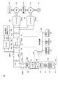
- FIG. 6 is a configuration diagram showing details of the vehicle 100 shown in FIGS. 1 and 5.
- vehicle 100 includes a main battery 150, a system main relay SMR1, a boost converter 162, inverters 164 and 166, motor generators 172 and 174, an engine 176, a power split device 177, Drive wheel 178.
- Vehicle 100 further includes a secondary self-resonant coil 112, a secondary coil 114, a rectifier 140, a DC / DC converter 142, a system main relay SMR2, and a voltage sensor 190.
- the vehicle 100 further includes a control device 180, a vehicle activation button 120, a communication unit 130, and a power supply button 122.
- This vehicle 100 is equipped with an engine 176 and a motor generator 174 as power sources.
- Engine 176 and motor generators 172 and 174 are connected to power split device 177.
- Vehicle 100 travels with a driving force generated by at least one of engine 176 and motor generator 174.
- the power generated by the engine 176 is divided into two paths by the power split device 177. That is, one is a path transmitted to the drive wheel 178 and the other is a path transmitted to the motor generator 172.
- Motor generator 172 is an AC rotating electrical machine, and includes, for example, a three-phase AC synchronous motor in which a permanent magnet is embedded in a rotor. Motor generator 172 generates power using the kinetic energy of engine 176 divided by power split device 177. For example, when the state of charge of main battery 150 (also referred to as “SOC (State Of Charge)”) becomes lower than a predetermined value, engine 176 starts and motor generator 172 generates power, and main Battery 150 is charged.
- SOC State Of Charge
- the motor generator 174 is also an AC rotating electric machine, and includes, for example, a three-phase AC synchronous motor in which a permanent magnet is embedded in a rotor, like the motor generator 172.
- Motor generator 174 generates driving force using at least one of the electric power stored in main battery 150 and the electric power generated by motor generator 172. Then, the driving force of motor generator 174 is transmitted to driving wheel 178.
- motor generator 174 when braking the vehicle or reducing acceleration on the down slope, the mechanical energy stored in the vehicle as kinetic energy or positional energy is used for rotational driving of the motor generator 174 via the drive wheels 178, and the motor generator 174 is Operates as a generator.
- motor generator 174 operates as a regenerative brake that converts running energy into electric power and generates braking force.
- the electric power generated by motor generator 174 is stored in main battery 150.
- the power split device 177 can use a planetary gear including a sun gear, a pinion gear, a carrier, and a ring gear.
- the pinion gear engages with the sun gear and the ring gear.
- the carrier supports the pinion gear so as to be able to rotate and is coupled to the crankshaft of the engine 176.
- the sun gear is coupled to the rotation shaft of motor generator 172.
- the ring gear is connected to the rotation shaft of motor generator 174 and drive wheel 178.
- the main battery 150 is a rechargeable DC power source, and includes, for example, a secondary battery such as a lithium ion battery or a nickel metal hydride battery.
- Main battery 150 stores electric power supplied from DC / DC converter 142 and also stores electric power generated by motor generators 172 and 174.
- Main battery 150 supplies the stored power to boost converter 162.
- a large-capacity capacitor can also be used as the main battery 150.
- Main battery 150 is a power buffer that can temporarily store power supplied from power supply apparatus 200 (FIG. 1) and regenerative power from motor generators 172 and 174 and supply the stored power to boost converter 162. It can be anything.
- the system main relay SMR1 is disposed between the main battery 150 and the boost converter 162.
- System main relay SMR1 electrically connects main battery 150 to boost converter 162 when signal SE1 from control device 180 is activated, and main battery 150 and boost converter when signal SE1 is deactivated.
- the electric path to 162 is cut off.
- Boost converter 162 boosts the voltage of positive line PL ⁇ b> 2 to a voltage equal to or higher than the voltage output from main battery 150 based on signal PWC from control device 180.
- Boost converter 162 includes a DC chopper circuit, for example.
- Inverters 164 and 166 are provided corresponding to motor generators 172 and 174, respectively. Inverter 164 drives motor generator 172 based on signal PWI 1 from control device 180, and inverter 166 drives motor generator 174 based on signal PWI 2 from control device 180. Inverters 164 and 166 include, for example, a three-phase bridge circuit.
- the secondary self-resonant coil 112 is connected to the capacitor 111 at both ends via a switch (relay 113).
- the switch (relay 113) When the switch (relay 113) is in a conductive state, the secondary self-resonant coil 112 is connected to the primary resonant coil and the electromagnetic field via the primary resonant coil. Resonate. Due to this resonance, power is received from the power supply apparatus 200 of FIGS.
- FIG. 6 shows an example in which the capacitor 111 is provided, the primary self-resonant coil may be adjusted so as to resonate with the stray capacitance of the coil instead of the capacitor.
- the secondary self-resonant coil 112 has a larger Q value (for example, Q> 100) indicating the distance from the primary self-resonant coil of the power feeding apparatus 200 and the resonance strength between the primary self-resonant coil and the secondary self-resonant coil 112. And the number of turns is appropriately set so that ⁇ indicating the degree of coupling becomes small.
- the secondary coil 114 is disposed coaxially with the secondary self-resonant coil 112 and can be magnetically coupled to the secondary self-resonant coil 112 by electromagnetic induction.
- the secondary coil 114 takes out the electric power received by the secondary self-resonant coil 112 by electromagnetic induction and outputs it to the rectifier 140.
- the secondary self-resonant coil 112 and the secondary coil 114 form the power receiving unit 110 shown in FIG.
- the rectifier 140 rectifies the AC power extracted by the secondary coil 114.
- DC / DC converter 142 converts the power rectified by rectifier 140 into a voltage level of main battery 150 based on signal PWD from control device 180 and outputs the voltage to main battery 150.
- the system main relay SMR2 is disposed between the DC / DC converter 142 and the main battery 150.
- System main relay SMR2 electrically connects main battery 150 to DC / DC converter 142 when signal SE2 from control device 180 is activated, and main battery 150 when signal SE2 is deactivated.
- the electric circuit between the DC / DC converter 142 is cut off.
- Voltage sensor 190 detects voltage VR between rectifier 140 and DC / DC converter 142 and outputs the detected value to control device 180.
- a resistor 144 and a relay 146 connected in series are provided between the rectifier 140 and the DC / DC converter 142.
- Relay 146 is controlled to be in a conductive state by control device 180 when the vehicle position is adjusted when vehicle 100 performs non-contact power feeding.
- Control device 180 generates signals PWC, PWI1, and PWI2 for driving boost converter 162 and motor generators 172 and 174, respectively, based on accelerator opening, vehicle speed, and other signals from various sensors. Control device 180 outputs generated signals PWC, PWI1, and PWI2 to boost converter 162 and inverters 164 and 166, respectively. When the vehicle travels, control device 180 activates signal SE1 to turn on system main relay SMR1, and deactivates signal SE2 to turn off system main relay SMR2.
- control device 180 transmits a power supply command to power supply device 200 via communication unit 130 and activates signal SE2 to turn on system main relay SMR2. Then, control device 180 generates a signal PWD for driving DC / DC converter 142 and outputs the generated signal PWD to DC / DC converter 142.
- Vehicle 100 is further provided between auxiliary battery 182, power lines PL1 and NL, and auxiliary battery 182, and reduces the voltage of main battery 150 to supply the auxiliary load and auxiliary battery 182 to DC / DC.
- Converter 181 and resonance device power supply unit 184 are included.
- the resonance device power supply unit 184 is one of auxiliary loads, but supplies power to the in-vehicle electric device in a non-contact manner.
- the non-contact power supply method of the resonance device power supply unit 184 employs a resonance method.
- the in-car electrical device is a mobile phone
- the device power supply unit is a unit that charges the battery of the mobile phone.
- the in-car electrical device does not necessarily have to be equipped with a battery, and it supplies power without contact. As long as this is performed.
- Other examples of in-car electrical equipment include personal computers, music equipment, digital cameras, video cameras, game machines, wireless communication equipment, and the like. These are not limited, but are often portable and compact.
- the power received by the power receiving unit 110 from the external power transmission device installed outside the vehicle in a contactless manner is larger than the power transmitted by the resonance device power supply unit 184 to the electrical equipment in the vehicle without contact.
- the capacity of the main battery 150 of the vehicle is much larger than the capacity of the battery built in the in-vehicle electric device such as a mobile phone.
- the resonance method is used when charging the main battery 150 of the vehicle, and the resonance method using electromagnetic waves having a frequency different from the charging of the main battery 150 is used when supplying electric power to the in-vehicle electric device. Mutual influences can be eliminated in contact power transmission and reception.
- the main battery 150 of the vehicle is charged without affecting the in-vehicle electric device by selecting the resonance frequency of the resonance portion to be different from the resonance frequency of the general in-vehicle electric device. Can be done.
- the resonance frequency of the resonance unit (secondary self-resonant coil 112 of the power reception unit 110) is determined by an LC component determined by the inductance L of the power reception unit related to the coil diameter and the capacitance C of the capacitor connected to the coil. Since the portable in-vehicle electric device is not as large as the vehicle, an inductance L that cannot be mounted on the general in-vehicle electric device may be mounted on the vehicle side.
- FIG. 7 is a circuit diagram for explaining the power reception unit 110 on the vehicle side and the power transmission unit 220 on the power feeding apparatus side in more detail.
- high-frequency power supply device 210 is represented by a high-frequency AC power supply 213 and a resistor 211 that indicates the impedance of the power supply.
- the power transmission unit 220 includes a primary coil 232 connected to the high frequency power supply device 210, a primary self-resonant coil 234 magnetically coupled to the primary coil 232 by electromagnetic induction, and capacitors connected to both ends of the primary self-resonant coil 234. 242.
- the power receiving unit 110 includes a secondary self-resonant coil 112 that resonates with the primary self-resonant coil 234 via an electromagnetic field, and a capacitor 111 and a relay 113 connected in series to both ends of the secondary self-resonant coil 112.
- the relay 113 is controlled to be in a conductive state when receiving power.
- the power receiving unit 110 further includes a secondary coil 114 that is magnetically coupled to the secondary self-resonant coil 112.
- the AC power received by the secondary coil 114 is rectified by the rectifier 140.
- a capacitor C1 is connected to the output of the rectifier 140, and a relay 146 and a resistor 144 used for adjusting the position of the vehicle and the power supply equipment are connected between the electrodes of the capacitor C1.
- a charger DC / DC converter 142 is further connected to the output side of the rectifier 140 to convert the voltage into an appropriate charging voltage, and the converted charging voltage is applied to the battery (main battery 150).
- the resistor 144 is set to an impedance of 50 ⁇ , for example, and this value is adjusted to match the impedance represented by the resistor 211 of the high frequency power supply device 210.
- the voltage sensor 190 detects the voltage at both ends of the resistor 144 and outputs the detected value VR to the control device 180 when adjusting the stop position of the vehicle when non-contact power feeding is performed on the vehicle.
- the voltage sensor 190 detects the input voltage to the DC / DC converter 142 as the detection value VR.
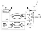
- FIG. 8 is a circuit diagram showing the configuration of the resonance device power supply unit 184 and the power reception unit of the in-vehicle electric device in FIG.
- the vehicle power transmission / reception system includes a resonance device power supply unit 184 incorporated in a vehicle that charges an electric device, and a power reception device built in vehicle electric device 400 that is powered by resonance device power supply unit 184.
- the unit 410 is configured to be included.
- the in-vehicle electric device 400 is, for example, a mobile phone, a personal computer, a digital camera, a PDA, a portable music player, or other portable electric devices.
- the in-car electrical device 400 includes a power reception unit 410, a communication unit 460, a rectifier 480, a charging connection circuit 470, a battery 490, a power switch 415, a load circuit 420, a device control unit 402, a current sensor 471, , And a voltage sensor 472.
- Power reception unit 410 includes a secondary resonance coil 411, a capacitor 412, and a secondary coil 413.
- the secondary resonance coil 411 receives power from the primary resonance coil 521 included in the resonance device power supply unit 184 by electromagnetic resonance using an electromagnetic field.
- the primary resonance coil 521 and the secondary resonance coil 521 are arranged based on the distance from the primary resonance coil 521 of the resonance device power supply unit 184, the resonance frequencies of the primary resonance coil 521 and the secondary resonance coil 411, and the like.
- the number of turns is appropriately set so that the Q value (for example, Q> 100) indicating the resonance intensity with the coil 411 is increased and ⁇ indicating the coupling degree is decreased.
- the capacitor 412 is connected to both ends of the secondary resonance coil 411 and forms an LC resonance circuit together with the secondary resonance coil 411.
- the capacity of the capacitor 412 is appropriately set so as to have a predetermined resonance frequency according to the inductance of the secondary resonance coil 411. Note that the capacitor 412 may be omitted when a desired resonance frequency is obtained with the stray capacitance of the secondary resonance coil 411 itself.
- the secondary coil 413 is provided coaxially with the secondary resonance coil 411, and can be magnetically coupled to the secondary resonance coil 411 by electromagnetic induction.
- the secondary coil 413 takes out the electric power received by the secondary resonance coil 411 by electromagnetic induction and outputs it to the rectifier 480.
- the rectifier 480 rectifies the AC power received from the secondary coil 413 and outputs the rectified DC power to the battery 490 via the charging connection circuit 470.
- the rectifier 480 may include a diode bridge and a smoothing capacitor (both not shown).
- a so-called switching regulator that performs rectification using switching control can be used.
- the rectifier 480 may be included in the power receiving unit 410, and prevents malfunction of the switching element due to the generated electromagnetic field. Therefore, it is more preferable to use a static rectifier such as a diode bridge.
- the DC power rectified by the rectifier 480 is directly output to the battery 490.
- a DC / DC converter (not shown) for voltage conversion may be provided between the rectifier 480 and the battery 490.
- the voltage sensor 472 is provided between a pair of power lines connecting the rectifier 480 and the battery 490.
- the voltage sensor 472 detects the DC voltage on the secondary side of the rectifier 480, that is, the received voltage received from the resonant device power supply unit 184, and outputs the detected value VC to the device control unit 402.
- the current sensor 471 is provided on a power line connecting the rectifier 480 and the battery 490.
- Current sensor 471 detects a charging current for battery 490 and outputs the detected value IC to device control unit 402.
- the charging connection circuit 470 is electrically connected to the rectifier 480 and the battery 490.
- the charge connection circuit 470 is controlled by a control signal SE12 from the device control unit 402, and switches between supply and interruption of power from the rectifier 480 to the battery 490.
- the battery 490 is a power storage element configured to be chargeable / dischargeable.
- Battery 490 includes, for example, a secondary battery such as a lithium ion battery, a nickel metal hydride battery, or a lead storage battery, and a storage element such as an electric double layer capacitor.
- the battery 490 is connected to the rectifier 480 via the charging connection circuit 470.
- the battery 490 stores the power received by the power receiving unit 410 and rectified by the rectifier 480.
- Battery 490 is also connected to load circuit 420 via power switch 415.
- Battery 490 supplies electric power for generating vehicle driving force to load circuit 420.
- the output of the battery 490 is about 3.6V, for example.
- battery 490 is provided with a voltage sensor and a current sensor for detecting voltage VB of battery 490 and input / output current IB. These detection values are output to the device control unit 402.
- Device control unit 402 calculates or estimates the state of charge of battery 490 (also referred to as “SOC (State Of Charge)”) based on voltage VB and current IB.
- the power switch 415 is provided on a power line connecting the battery 490 and the load circuit 420.
- the power switch 415 is controlled by a control signal SE11 from the device control unit 402, and switches between power supply and interruption between the battery 490 and the load circuit 420.
- the communication unit 460 is a communication interface for performing wireless communication between the in-vehicle electric device 400 and the resonance device power supply unit 184.
- the communication unit 460 outputs battery information INFO including the SOC for the battery 490 from the device control unit 402 to the resonance device power supply unit 184.
- the communication unit 460 outputs signals STRT and STP instructing start and stop of power transmission from the resonance device power supply unit 184 to the resonance device power supply unit 184.
- the device control unit 402 includes a CPU (Central Processing Unit), a storage device, and an input / output buffer, and inputs a signal from each sensor and outputs a control signal to each device.
- the in-car electrical device 400 and each device are controlled. Note that these controls are not limited to processing by software, and can be processed by dedicated hardware (electronic circuit).
- the device control unit 402 Upon receiving the charging start signal TRG due to the user's operation or alignment completion, the device control unit 402 sends a signal STRT for instructing the start of power transmission via the communication unit 460 based on a predetermined condition being satisfied. Output to the resonance device power supply unit 184. In addition, the device control unit 402 outputs a signal STP instructing to stop power transmission to the resonance device power supply unit 184 via the communication unit 460 based on the battery 490 being fully charged or an operation by the user. To do.
- the resonance device power supply unit 184 includes a power supply device 510 and a power transmission unit 520.
- Power supply device 510 includes a communication unit 530, a power transmission ECU 540 that is a control device, a high-frequency power supply unit 550, and a matching unit 560.
- Power transmission unit 520 includes a primary resonance coil 521, a capacitor 522, and a primary coil 523.
- the high frequency power supply unit 550 supplies the converted high frequency power to the primary coil 523 through the matching unit 560.
- the frequency f2 of the high frequency power generated by the high frequency power supply unit 550 is, for example, 1M to several tens of MHz.
- the frequencies f1 and f2 are set so that the frequency f2 is different from the frequency f1 of the high-frequency power supply device of FIG.
- the frequency f2 may be set lower than the frequency f1, but the frequency f2 is preferably set higher than the frequency f1 of the high frequency power supply device of FIG.
- the matching unit 560 is a circuit for matching the impedance between the resonance device power supply unit 184 and the in-car electrical device 400.
- Matching device 560 includes a variable capacitor and a variable inductor.
- Matching device 560 is controlled by control signal ADJ provided from power transmission ECU 540 based on battery information INFO transmitted from in-car electrical device 400 so that the impedance of resonant device power supply unit 184 matches the impedance on in-car electrical device 400 side.
- a variable capacitor and a variable inductor are adjusted.
- Matching device 560 outputs signal COMP indicating that the impedance adjustment is completed to power transmission ECU 540.
- the primary resonance coil 521 transfers electric power to the secondary resonance coil 411 included in the power reception unit 410 of the in-vehicle electric device 400 by electromagnetic resonance.
- the primary resonance coil 521 and the secondary resonance coil are based on the distance from the secondary resonance coil 411 of the in-vehicle electrical device 400, the resonance frequencies of the primary resonance coil 521 and the secondary resonance coil 411, and the like.
- the number of turns is appropriately set so that the Q value (for example, Q> 100) indicating the resonance intensity with 411 is increased and ⁇ indicating the coupling degree is decreased.
- the capacitor 522 is connected to both ends of the primary resonance coil 521 and forms an LC resonance circuit together with the primary resonance coil 521.
- the capacity of the capacitor 522 is appropriately set so as to have a predetermined resonance frequency according to the inductance of the primary resonance coil 521. Note that the capacitor 522 may be omitted when a desired resonance frequency can be obtained with the stray capacitance of the primary resonance coil 521 itself.
- the primary coil 523 is provided coaxially with the primary resonance coil 521, and can be magnetically coupled to the primary resonance coil 521 by electromagnetic induction.
- the primary coil 523 transmits the high frequency power supplied through the matching unit 560 to the primary resonance coil 521 by electromagnetic induction.
- the communication unit 530 is a communication interface for performing wireless communication between the resonance device power supply unit 184 and the in-vehicle electrical device 400 as described above.
- Communication unit 530 receives battery information INFO transmitted from communication unit 460 on in-car electrical device 400 side, and signals STRT and STP instructing start and stop of power transmission, and outputs these information to power transmission ECU 540.
- Communication unit 530 receives signal COMP indicating that the impedance adjustment from matching unit 560 has been completed from power transmission ECU 540 and outputs the signal COMP to in-vehicle electrical apparatus 400 side.
- the power transmission ECU 540 includes a CPU, a storage device, and an input / output buffer (not shown in FIG. 8).
- the power transmission ECU 540 inputs a signal from each sensor or the like and outputs a control signal to each device. Control the equipment. Note that these controls are not limited to processing by software, and can be processed by dedicated hardware (electronic circuit).
- the in-vehicle electric device 400 does not necessarily require the battery 490.
- the battery 490 does not need to be built in the in-car electrical device 400 as long as it supplies power to the in-car electrical device 400 without contact.
- FIG. 9 is a diagram for explaining an arrangement example of the resonance device power supply unit 184 of FIG. 8 in the vehicle.
- the resonance device power supply unit 184 is preferably disposed at a position in the passenger compartment that can be used from both the driver seat 502 and the passenger seat 504.
- the resonance device power supply unit 184 may be provided in a tray of the center console 506, a pocket of the dashboard, or the like.
- FIG. 9 shows an example in which the resonance device power supply unit 184 is provided in the center console 506 and the tray bottom surface on which the in-vehicle electrical device 400 is placed is the device arrangement surface 191.
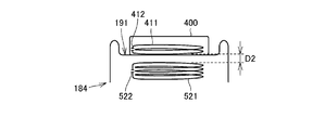
- FIG. 10 is a diagram for explaining the distance between the coil of the in-vehicle electric device and the coil of the device power supply unit.
- in-vehicle electric device 400 and resonance device are configured such that distance D2 of power reception side coil 404 built in or attached to in-vehicle electric device 400 is equal to distance D ⁇ b> 2 from power supply side coil 194 of resonance device power supply unit 184.
- the housing of the power supply unit 184 is designed.
- FIG. 10 shows an example in which the distance D2 is smaller than the distance D1 shown in FIG.
- the resonance method can achieve practical efficiency even if the distance for non-contact power transmission is 3 to 4 m.
- the resonance device power supply unit 184 when the power transmitted to the in-car electrical device 400 by the resonance device power supply unit 184 is sufficiently small, for example, the user does not have to place the in-car electrical device 400 at a designated location as shown in FIGS. It is also possible to charge the battery while holding it.
- the in-vehicle electrical device 400 is electrically non-contact with the resonance device power supply unit 184 but physically has a device arrangement surface 191 in which the housings are in contact with each other.
- the casing is provided with unevenness and magnets for alignment, and the user lifts the in-car electric device 400 by hand and places it on the device arrangement surface 191 of the resonance device power supply unit 184 to adjust the position by hand.
- This point is greatly different from the alignment of the power transmission unit 220 and the power reception unit 110 in FIG.
- the resonance method using the resonance frequencies different from each other is used.
- the in-vehicle device can be prevented from receiving power due to resonance of the low-power in-vehicle device with the resonance frequency for receiving power to the in-vehicle battery.
- the resonance frequency when the resonance frequency is lowered, the cost of a unit such as a resonance coil can be reduced particularly when a large power is handled. Conversely, when handling low power, it is easy to increase the resonance frequency. Therefore, the overall vehicle cost can be reduced by setting the resonance frequency of the power receiving unit for the in-vehicle battery of high power to be lower than the resonance frequency of the power supply unit for in-vehicle electric equipment that is low power. .
- FIG. 11 is a flowchart for explaining control related to permission of power transmission / reception performed by the control device 180 of FIG.
- the processing of this flowchart is called and executed from the main routine of vehicle control every predetermined time or every time a predetermined condition is satisfied.
- control device 180 determines whether or not the vehicle is in a vehicle non-travelable state in step S1.
- the vehicle when the vehicle is in a vehicle non-travelable state (Ready-OFF state), the vehicle enters a travelable state (Ready-ON state) by pressing the vehicle start button 120 once, and the shift range is set to the drive range.
- the accelerator pedal When the accelerator pedal is depressed, the vehicle can start.
- pressing the vehicle start button 120 once again causes the vehicle to be in a vehicle travel-impossible state (Ready-OFF state), and the vehicle does not start even if the accelerator pedal is depressed. It becomes a state.
- system main relay SMR1 in FIG. 6 is conductive, motor generators 172 and 174 can be energized, and engine 176 can also be operated.
- system main relay SMR1 in FIG. 6 is non-conductive, motor generators 172 and 174 are prohibited from being energized, and engine 176 is also prohibited from operating.
- step S1 If it is determined in step S1 that the vehicle is not ready to travel (Ready-OFF), the process proceeds to step S2. If the vehicle is ready to travel (Ready-ON), the process proceeds to step S7.
- control device 180 determines whether or not there is a charge request for main battery 150.
- the charge request for the main battery 150 may be given from, for example, an input device (such as the power supply button 122 in FIG. 6) operated by the driver, or the positioning of the power transmission unit 220 and the power reception unit 110 in FIG. 1 has been completed.
- Control device 180 itself may be generated based on the signal indicating the state of charge and the state of charge (SOC) of main battery 150.
- step S2 if there is a charge request for main battery 150, the process proceeds from step S2 to step S3, and if there is no charge request, the process proceeds from step S2 to step S5.
- step S3 the system main relay SMR1 is controlled to be turned off while the system main relay SMR2 is turned on.
- step S4 charging of the main battery 150 is permitted, but power feeding to the in-vehicle electrical device is prohibited. In this state, it is also assumed that the driver is away from the vehicle while the main battery 150 is being charged.
- step S5 system main relays SMR1 and SMR2 are both controlled to be in an off state.
- step S6 charging of the main battery 150 and power feeding to the in-vehicle electrical device are both prohibited.
- step S1 when the vehicle is in a travelable state (Ready-ON) and the process proceeds to step S7, system main relay SMR1 is controlled to be in an on state, and the vehicle can be energized to motor generators 172 and 174. It becomes a state. In this state, it is assumed that the driver remains in the vehicle, and auxiliary equipment such as an air conditioner and audio equipment (not shown) can be used. Then, in step S8, it is determined whether or not there is a request for charging the main battery 150.
- auxiliary equipment such as an air conditioner and audio equipment
- step S8 If there is a charge request for the main battery 150 in step S8, the process proceeds to step S9, and if there is no charge request, the process proceeds to step S11.
- step S9 system main relays SMR1 and SMR2 are both controlled to be on.
- step S10 charging of the main battery 150 and power feeding to the in-vehicle electric device are both permitted.
- step S11 the system main relay SMR1 is controlled to be turned on while the system main relay SMR2 is turned off.
- step S12 charging of the main battery 150 is prohibited, while power feeding to the in-vehicle electric device is permitted.
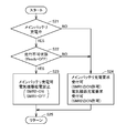
- FIG. 12 is a flowchart for explaining the control of the modified example related to the permission of power transmission / reception performed by the control device 180 of FIG.
- the processing of this flowchart is called and executed from the main routine of vehicle control every predetermined time or every time a predetermined condition is satisfied.
- control device 180 determines whether or not main battery 150 is being charged in step S21. If the main battery 150 is not being charged in step S21, the process proceeds to step S24. If the main battery 150 is being charged, the process proceeds to step S22.
- step S22 it is determined whether or not the current vehicle state is a non-travelable state (Ready-OFF state). If it is determined in step S22 that the vehicle is in a travel-disabled state, the process proceeds to step S23. If the vehicle is not travel-disabled, that is, if it is in a travelable state (Ready-ON state), the process proceeds to step S24. Advances.
- step S23 the control device 180 controls the system main relays SMR1 and SMR2, the DC / DC converter 142, the resonance device power supply unit so that the main battery 150 can be charged and power supply to the in-vehicle electric device is prohibited. 184 is controlled.
- control device 180 includes system main relays SMR1 and SMR2, DC / DC converter 142 so that a request for charging main battery 150 can be received and a power supply request can be received for in-vehicle electrical equipment.
- the resonance device power supply unit 184 is controlled.
- the driver when the driver leaves the vehicle while the main battery 150 is being charged, the driver sets the vehicle in an untravelable state before that. In such a case, power supply to the in-vehicle electrical device is prohibited, so that it is possible to avoid an unexpected situation by supplying power to the in-vehicle electrical device in the absence of a driver or other passenger. .
- vehicle 100 has a power receiving unit 110 that receives electric power for traveling of vehicle 100 in a contactless manner by electromagnetic resonance, and a contactless power that is supplied to an electric device inside the vehicle by electromagnetic resonance. And a resonance device power supply unit 184 for transmitting power.
- the frequency of the electromagnetic field used for power reception by the power receiving unit 110 and the frequency of the electromagnetic field used for power transmission by the resonance device power supply unit 184 are set differently.
- the power receiving unit 110 receives power so that the frequency of the electromagnetic field used for power reception (f1 in FIG. 5) is lower than the frequency of the electromagnetic field used by the resonant device power supply unit 184 for power transmission (f2 in FIG. 8).
- the frequency of the electromagnetic field used by the unit 110 for power reception (f1 in FIG. 5) and the frequency of the electromagnetic field used by the resonance device power supply unit 184 for power transmission (f2 in FIG. 8) are set.
- the power received by the power receiving unit 110 in a contactless manner from the power feeding device 200 installed outside the vehicle is larger than the power transmitted by the resonance device power supply unit 184 to the in-vehicle electrical device 400 in a contactless manner.
- vehicle 100 includes motor generators 172 and 174 that drive vehicle 100, main battery 150 that supplies electric power to motor generators 172 and 174, and auxiliary battery 182 that is provided separately from main battery 150.
- the voltage of the auxiliary battery 182 is lower than the voltage of the main battery 150, and the resonance device power supply unit 184 receives power from the auxiliary battery 182 and transmits power to the in-vehicle electric device 400.
- control device 180 permits charging of main battery 150 with the power received by power receiving unit 110 in the travelable state (NO in step S22), and from resonance device power supply unit 184. Allowing electric power to be supplied to the in-car electrical device 400 is permitted. Control device 180 permits charging of main battery 150 with the power received by power receiving unit 110 in a state in which traveling is not possible (YES in step S22), and electric device 400 in vehicle interior from resonance device power supply unit 184. Prohibit supplying power to
- the present invention is an in-vehicle electric device 400 used inside a vehicle.
- the vehicle 100 receives power for driving the vehicle 100 from the power supply apparatus 200 in a contactless manner by electromagnetic resonance, and resonance that transmits power supplied to the in-vehicle electrical device 400 in a contactless manner by electromagnetic resonance.
- the in-car electrical device 400 includes a power receiving unit 410 that receives power transmitted from the resonance device power supply unit 184 using an electromagnetic field frequency higher than the frequency of the electromagnetic field used by the power receiving unit 110 of the vehicle 100 for power reception. .
- the present invention is a power transmission / reception system, which is a vehicle 100, a power supply device 200 that transmits electric power to the vehicle 100 in a contactless manner by electromagnetic resonance, and an interior of the vehicle that can be used inside the vehicle.
- Electrical equipment 400 The vehicle 100 transmits the power for driving the vehicle from the external power supply device 200 in a contactless manner by electromagnetic resonance and the power supplied to the in-vehicle electric device 400 in a contactless manner by the electromagnetic resonance.
- Resonance device power supply unit 184 The frequency of the electromagnetic field used for power reception by the power receiving unit 110 and the frequency of the electromagnetic field used for power transmission by the resonance device power supply unit 184 are set differently.
- FIGS. 6 and 7 an example including the secondary self-resonant coil 112 and the secondary coil 114 is shown in FIGS. 6 and 7, but the present invention is not limited to such a configuration.
- the present invention is applicable even if the power is not transmitted between the secondary self-resonant coil 112 and the secondary coil 114 by induction.
- any device that uses a resonance method for power reception of a vehicle may be used, and the present invention can be applied to a device that does not have a coil that performs power reception by electromagnetic induction.
- FIGS. 6, 7, 8, and the like an example including a primary self-resonant coil, a primary coil, a secondary self-resonant coil, and a secondary coil is shown in FIGS. 6, 7, 8, and the like, but the present invention has such a configuration.
- the power transmission between the secondary self-resonant coil 112 and the secondary coil 114, the power transmission between the primary coil and the 232 primary self-resonant coil 234, and the electromagnetic induction are not limited to the above. Therefore, the present invention can be applied even if the power transmission between the secondary self-resonant coil 411 and the secondary coil 413 and the power transmission between the primary coil 523 and the primary self-resonant coil 521 are not performed.
- it may be anything that uses a resonance method for power transmission / reception to / from a vehicle or electric equipment in a vehicle, and is also applicable to a device that does not have a coil that performs electromagnetic induction on the resonance power transmission / reception path. Is possible.
- 10 power transmission / reception system 100 vehicle, 110 power receiving unit, 111, 242, 412, 522, C1 capacitor, 112, 340 secondary self-resonant coil, 113, 146 relay, 114, 350, 413 secondary coil, 120 vehicle start Button, 122 power supply button, 130, 240 communication unit, 140, 480 rectifier, 142, 181 DC / DC converter, 144, 211 resistance, 150 main battery, 162 boost converter, 164, 166 inverter, 172, 174 motor generator, 176 Engine, 177 power split device, 178 drive wheel, 180 control device, 182 auxiliary battery, 184 resonance device power supply unit, 190,472 voltage sensor, 191 device placement surface, 194 power supply Coil, 200 power supply device, 210 high frequency power supply device, 212 connector, 213 high frequency AC power supply, 220 power transmission unit, 232, 320, 523 primary coil, 234, 330 primary self-resonant coil, 310 high frequency power supply, 360 load, 400 in-car electrical equipment
Landscapes
- Engineering & Computer Science (AREA)
- Power Engineering (AREA)
- Transportation (AREA)
- Mechanical Engineering (AREA)
- Computer Networks & Wireless Communication (AREA)
- Charge And Discharge Circuits For Batteries Or The Like (AREA)
- Electric Propulsion And Braking For Vehicles (AREA)
- Current-Collector Devices For Electrically Propelled Vehicles (AREA)
Abstract
Description
図1を参照して、電力送受電システム10は、車両100と、給電装置200とを含む。車両100は、受電ユニット110と、通信ユニット130とを含む。
図2を参照して、この共鳴法では、2つの音叉が共鳴するのと同様に、同じ固有振動数を有する2つのLC共振コイルが電磁場(近接場)において共鳴することによって、一方のコイルから他方のコイルへ電磁場を介して電力が伝送される。
図3を参照して、電磁界は3つの成分を含む。曲線k1は、波源からの距離に反比例した成分であり、「輻射電磁界」と称される。曲線k2は、波源からの距離の2乗に反比例した成分であり、「誘導電磁界」と称される。また、曲線k3は、波源からの距離の3乗に反比例した成分であり、「静電磁界」と称される。
図6を参照して、車両100は、メインバッテリ150と、システムメインリレーSMR1と、昇圧コンバータ162と、インバータ164,166と、モータジェネレータ172,174と、エンジン176と、動力分割装置177と、駆動輪178とを含む。
Claims (8)
- 車両(100)の走行のための電力を電磁界共鳴によって非接触で受電する受電装置(110)と、
前記車両内部で電気機器に供給する電力を電磁界共鳴によって非接触で送電する送電装置(184)とを備え、
前記受電装置が受電に使用する電磁界の周波数と前記送電装置が送電に使用する電磁界の周波数とは異なるように設定される、車両。 - 前記受電装置が受電に使用する電磁界の周波数が前記送電装置が送電に使用する電磁界の周波数よりも低くなるように、前記受電装置が受電に使用する電磁界の周波数と前記送電装置が送電に使用する電磁界の周波数とが設定される、請求項1に記載の車両。
- 前記受電装置が車両外部に設置された外部送電装置から非接触で受電する電力は、前記送電装置が非接触で前記電気機器に送電する電力よりも大きい、請求項2に記載の車両。
- 車両を駆動する駆動装置(172,174)と、
前記駆動装置に電力を供給する主バッテリ(150)と、
前記主バッテリとは別に設けられた補機バッテリ(182)とをさらに備え、
前記補機バッテリの電圧は、前記主バッテリの電圧よりも低く、
前記送電装置は前記補機バッテリから電力を受けて前記電気機器に送電を行なう、請求項3に記載の車両。 - 乗員の操作に応じて車両の動作状態を走行可能状態と走行不可能状態に設定する制御部(180)をさらに備え、
前記制御部は、前記走行可能状態においては前記受電装置によって受電された電力を前記主バッテリに充電することを許可し、かつ前記送電装置から前記電気機器に電力を供給することを許可し、前記走行不可能状態においては前記受電装置によって受電された電力を前記主バッテリに充電することを許可し、かつ前記送電装置から前記電気機器に電力を供給することを禁止する、請求項4に記載の車両。 - 車両内部で使用される電気機器(400)であって、
前記車両は、
外部送電装置から前記車両の走行のための電力を電磁界共鳴によって非接触で受電する受電装置(110)と、
前記電気機器に供給する電力を電磁界共鳴によって非接触で送電する送電装置(184)とを含み、
前記電気機器は、
前記車両の前記受電装置が受電に使用する電磁界の周波数とは異なる電磁界の周波数を使用して、前記送電装置から送電される電力を受ける受電部(410)を備える、電気機器。 - 前記受電部は、前記車両の前記受電装置が受電に使用する電磁界の周波数よりも高い電磁界の周波数を使用して、前記送電装置から送電される電力を受ける、請求項6に記載の電気機器。
- 車両(100)と、
前記車両に電力を電磁界共鳴によって非接触で送電する外部送電装置(200)と、
前記車両内部で使用することができる電気機器(400)とを備え、
前記車両は、
前記外部送電装置から前記車両の走行のための電力を電磁界共鳴によって非接触で受電する受電装置(110)と、
前記電気機器に供給する電力を電磁界共鳴によって非接触で送電する送電装置(184)とを含み、
前記受電装置が受電に使用する電磁界の周波数と前記送電装置が送電に使用する電磁界の周波数とは異なるように設定される、電力送受電システム。
Priority Applications (8)
| Application Number | Priority Date | Filing Date | Title |
|---|---|---|---|
| KR1020137031935A KR101561761B1 (ko) | 2011-06-03 | 2011-06-03 | 차량 |
| JP2013517794A JP5768878B2 (ja) | 2011-06-03 | 2011-06-03 | 車両 |
| PCT/JP2011/062817 WO2012164743A1 (ja) | 2011-06-03 | 2011-06-03 | 車両、電気機器および電力送受電システム |
| RU2013153392/11A RU2013153392A (ru) | 2011-06-03 | 2011-06-03 | Транспортное средство, электрическое устройство и система приема/передачи мощности |
| CN201180071356.9A CN103561995B (zh) | 2011-06-03 | 2011-06-03 | 车辆、电气设备以及电力送受电系统 |
| EP11866540.5A EP2716488B1 (en) | 2011-06-03 | 2011-06-03 | Vehicle, electric device, and power transmission/reception system |
| US14/123,367 US9162581B2 (en) | 2011-06-03 | 2011-06-03 | Vehicle, electric device, and power transmission/reception system |
| BR112013031015A BR112013031015A2 (pt) | 2011-06-03 | 2011-06-03 | veículo, dispositivo elétrico, e sistema de transmissão/recepção de energia |
Applications Claiming Priority (1)
| Application Number | Priority Date | Filing Date | Title |
|---|---|---|---|
| PCT/JP2011/062817 WO2012164743A1 (ja) | 2011-06-03 | 2011-06-03 | 車両、電気機器および電力送受電システム |
Publications (1)
| Publication Number | Publication Date |
|---|---|
| WO2012164743A1 true WO2012164743A1 (ja) | 2012-12-06 |
Family
ID=47258628
Family Applications (1)
| Application Number | Title | Priority Date | Filing Date |
|---|---|---|---|
| PCT/JP2011/062817 WO2012164743A1 (ja) | 2011-06-03 | 2011-06-03 | 車両、電気機器および電力送受電システム |
Country Status (8)
| Country | Link |
|---|---|
| US (1) | US9162581B2 (ja) |
| EP (1) | EP2716488B1 (ja) |
| JP (1) | JP5768878B2 (ja) |
| KR (1) | KR101561761B1 (ja) |
| CN (1) | CN103561995B (ja) |
| BR (1) | BR112013031015A2 (ja) |
| RU (1) | RU2013153392A (ja) |
| WO (1) | WO2012164743A1 (ja) |
Cited By (3)
| Publication number | Priority date | Publication date | Assignee | Title |
|---|---|---|---|---|
| JP2015104253A (ja) * | 2013-11-26 | 2015-06-04 | 矢崎総業株式会社 | ワイヤレス給電システム |
| KR101555577B1 (ko) * | 2013-12-30 | 2015-09-24 | 전자부품연구원 | 무선 전력 전송 방법 |
| JP2017093162A (ja) * | 2015-11-10 | 2017-05-25 | 富士通株式会社 | 受電器 |
Families Citing this family (14)
| Publication number | Priority date | Publication date | Assignee | Title |
|---|---|---|---|---|
| EP2716489B1 (en) * | 2011-06-03 | 2018-11-21 | Toyota Jidosha Kabushiki Kaisha | Vehicle and power transmission/reception system |
| JP6156744B2 (ja) * | 2011-07-14 | 2017-07-05 | パナソニックIpマネジメント株式会社 | 充電装置および車両 |
| EP2769884B1 (en) * | 2011-10-20 | 2016-09-28 | Honda Motor Co., Ltd. | Method for controlling vehicle |
| US9531441B2 (en) | 2012-02-21 | 2016-12-27 | Lg Innotek Co., Ltd. | Wireless power receiver and method of managing power thereof |
| CA2981571C (en) * | 2015-04-07 | 2019-01-15 | Nissan Motor Co., Ltd. | A locking/unlocking system for a vehicle |
| JP6314934B2 (ja) * | 2015-08-07 | 2018-04-25 | トヨタ自動車株式会社 | 車両 |
| CN109478801B (zh) * | 2016-07-29 | 2024-03-26 | 索尼半导体解决方案公司 | 受电装置和电子设备 |
| DE102017204699A1 (de) * | 2017-03-21 | 2018-09-27 | Robert Bosch Gmbh | Energieversorgungsvorrichtung, Elektrofahrzeug und Verfahren zum Laden einer Batterie |
| DE102018203039B4 (de) * | 2018-03-01 | 2024-11-07 | Vitesco Technologies GmbH | Bordnetz für ein Kraftfahrzeug und Verfahren zum Betreiben eines Bordnetzes eines Kraftfahrzeugs |
| JP7091798B2 (ja) * | 2018-04-13 | 2022-06-28 | トヨタ自動車株式会社 | 車両充電システム、及び車両充電システムの認証方法 |
| US10861301B1 (en) * | 2019-06-24 | 2020-12-08 | Zealio Electronics Co., Ltd. | Multifunctional smart holder and control method thereof |
| JP7211385B2 (ja) * | 2020-02-28 | 2023-01-24 | トヨタ自動車株式会社 | シフトバイワイヤシステムの制御装置 |
| US11766947B2 (en) * | 2021-05-28 | 2023-09-26 | Zoox, Inc. | DC fast charger wireless-charging adapter |
| US20240116381A1 (en) * | 2022-10-10 | 2024-04-11 | Magna Electronics Inc. | Vehicular in-cabin manually operated power generator for powering vehicular accessory |
Citations (6)
| Publication number | Priority date | Publication date | Assignee | Title |
|---|---|---|---|---|
| JP2005110412A (ja) | 2003-09-30 | 2005-04-21 | Sharp Corp | 電力供給システム |
| JP2007104868A (ja) | 2005-10-07 | 2007-04-19 | Toyota Motor Corp | 車両用充電装置、電気機器及び車両用非接触充電システム |
| WO2010052785A1 (ja) | 2008-11-07 | 2010-05-14 | トヨタ自動車株式会社 | 車両用給電システム、電動車両および車両用給電設備 |
| JP2010268660A (ja) * | 2009-05-18 | 2010-11-25 | Toyota Motor Corp | 非接触電力伝達装置、車両および非接触電力伝達システム |
| JP2011034306A (ja) * | 2009-07-31 | 2011-02-17 | Toshiba Corp | 情報処理装置及び給電制御方法 |
| JP2011083078A (ja) * | 2009-10-05 | 2011-04-21 | Sony Corp | 送電装置、受電装置、および電力伝送システム |
Family Cites Families (17)
| Publication number | Priority date | Publication date | Assignee | Title |
|---|---|---|---|---|
| JP4425711B2 (ja) * | 2004-05-31 | 2010-03-03 | 京セラ株式会社 | アンテナ制御方法および無線送受信装置 |
| JP5517398B2 (ja) * | 2007-03-15 | 2014-06-11 | 三菱重工業株式会社 | 蓄電システム |
| JP4453741B2 (ja) | 2007-10-25 | 2010-04-21 | トヨタ自動車株式会社 | 電動車両および車両用給電装置 |
| US20090160261A1 (en) * | 2007-12-19 | 2009-06-25 | Nokia Corporation | Wireless energy transfer |
| JP5075683B2 (ja) * | 2008-03-05 | 2012-11-21 | 富士フイルム株式会社 | 非接触充電装置および非接触充電方法 |
| JP2009296780A (ja) * | 2008-06-04 | 2009-12-17 | Kojima Press Industry Co Ltd | 車載充電器 |
| JP4911148B2 (ja) * | 2008-09-02 | 2012-04-04 | ソニー株式会社 | 非接触給電装置 |
| US8421409B2 (en) * | 2008-09-19 | 2013-04-16 | Toyota Jidosha Kabushiki Kaisha | Noncontact power receiving apparatus for electrically-powered vehicle and vehicle including the same |
| CN102421628B (zh) * | 2009-05-14 | 2014-04-23 | 丰田自动车株式会社 | 车辆用充电装置 |
| JP5499534B2 (ja) | 2009-07-07 | 2014-05-21 | ソニー株式会社 | 非接触受電装置、非接触受電装置における受電方法および非接触給電システム |
| US8502412B2 (en) * | 2009-08-28 | 2013-08-06 | Toyota Jidosha Kabushiki Kaisha | Power supply system for vehicle and electrically-powered vehicle having the power supply system |
| JP5569952B2 (ja) * | 2009-09-03 | 2014-08-13 | Necカシオモバイルコミュニケーションズ株式会社 | 充電装置及び充電システム並びにプログラム |
| US9077194B2 (en) * | 2009-09-09 | 2015-07-07 | Auckland Uniservices Limited | Power demand management in inductive power transfer systems |
| WO2011036702A1 (ja) * | 2009-09-24 | 2011-03-31 | 株式会社 東芝 | 無線電力伝送システム |
| JP2011200052A (ja) * | 2010-03-23 | 2011-10-06 | Toyota Central R&D Labs Inc | 給電装置 |
| JP5691458B2 (ja) * | 2010-03-31 | 2015-04-01 | 日産自動車株式会社 | 非接触給電装置及び非接触給電方法 |
| EP2716489B1 (en) | 2011-06-03 | 2018-11-21 | Toyota Jidosha Kabushiki Kaisha | Vehicle and power transmission/reception system |
-
2011
- 2011-06-03 CN CN201180071356.9A patent/CN103561995B/zh active Active
- 2011-06-03 KR KR1020137031935A patent/KR101561761B1/ko active IP Right Grant
- 2011-06-03 EP EP11866540.5A patent/EP2716488B1/en active Active
- 2011-06-03 BR BR112013031015A patent/BR112013031015A2/pt not_active IP Right Cessation
- 2011-06-03 JP JP2013517794A patent/JP5768878B2/ja active Active
- 2011-06-03 US US14/123,367 patent/US9162581B2/en active Active
- 2011-06-03 WO PCT/JP2011/062817 patent/WO2012164743A1/ja active Application Filing
- 2011-06-03 RU RU2013153392/11A patent/RU2013153392A/ru not_active Application Discontinuation
Patent Citations (6)
| Publication number | Priority date | Publication date | Assignee | Title |
|---|---|---|---|---|
| JP2005110412A (ja) | 2003-09-30 | 2005-04-21 | Sharp Corp | 電力供給システム |
| JP2007104868A (ja) | 2005-10-07 | 2007-04-19 | Toyota Motor Corp | 車両用充電装置、電気機器及び車両用非接触充電システム |
| WO2010052785A1 (ja) | 2008-11-07 | 2010-05-14 | トヨタ自動車株式会社 | 車両用給電システム、電動車両および車両用給電設備 |
| JP2010268660A (ja) * | 2009-05-18 | 2010-11-25 | Toyota Motor Corp | 非接触電力伝達装置、車両および非接触電力伝達システム |
| JP2011034306A (ja) * | 2009-07-31 | 2011-02-17 | Toshiba Corp | 情報処理装置及び給電制御方法 |
| JP2011083078A (ja) * | 2009-10-05 | 2011-04-21 | Sony Corp | 送電装置、受電装置、および電力伝送システム |
Non-Patent Citations (1)
| Title |
|---|
| See also references of EP2716488A4 |
Cited By (3)
| Publication number | Priority date | Publication date | Assignee | Title |
|---|---|---|---|---|
| JP2015104253A (ja) * | 2013-11-26 | 2015-06-04 | 矢崎総業株式会社 | ワイヤレス給電システム |
| KR101555577B1 (ko) * | 2013-12-30 | 2015-09-24 | 전자부품연구원 | 무선 전력 전송 방법 |
| JP2017093162A (ja) * | 2015-11-10 | 2017-05-25 | 富士通株式会社 | 受電器 |
Also Published As
| Publication number | Publication date |
|---|---|
| JP5768878B2 (ja) | 2015-08-26 |
| EP2716488A4 (en) | 2015-09-23 |
| KR101561761B1 (ko) | 2015-10-19 |
| CN103561995A (zh) | 2014-02-05 |
| KR20140005355A (ko) | 2014-01-14 |
| BR112013031015A2 (pt) | 2016-11-29 |
| EP2716488B1 (en) | 2018-08-01 |
| US9162581B2 (en) | 2015-10-20 |
| EP2716488A1 (en) | 2014-04-09 |
| US20140103872A1 (en) | 2014-04-17 |
| JPWO2012164743A1 (ja) | 2014-07-31 |
| RU2013153392A (ru) | 2015-07-20 |
| CN103561995B (zh) | 2016-09-28 |
Similar Documents
| Publication | Publication Date | Title |
|---|---|---|
| JP5692372B2 (ja) | 車両および電力送受電システム | |
| JP5768878B2 (ja) | 車両 | |
| WO2013042229A1 (ja) | 非接触送電装置、非接触受電装置および非接触送受電システム | |
| JP5263391B2 (ja) | 非接触受電装置およびそれを備える車両 | |
| JP5146488B2 (ja) | 給電システムおよび車両 | |
| JP4947241B2 (ja) | コイルユニット、非接触受電装置、非接触送電装置、非接触給電システムおよび車両 | |
| JP4453741B2 (ja) | 電動車両および車両用給電装置 | |
| JP5016069B2 (ja) | 電力伝送システムおよび車両用給電装置 | |
| JP5700133B2 (ja) | 非接触受電装置、非接触送電装置および非接触送受電システム | |
| JP5304624B2 (ja) | 給電装置、車両および車両給電システム | |
| JP5884830B2 (ja) | 非接触受電装置、非接触送電装置および非接触送受電システム | |
| JP5474470B2 (ja) | 非接触受電装置およびそれを備える電動車両 | |
| JP5287115B2 (ja) | 車両の受電制御装置およびそれを備える車両 | |
| JP2015027224A (ja) | 非接触受電装置 | |
| JPWO2013042229A1 (ja) | 非接触送電装置、非接触受電装置および非接触送受電システム |
Legal Events
| Date | Code | Title | Description |
|---|---|---|---|
| 121 | Ep: the epo has been informed by wipo that ep was designated in this application |
Ref document number: 11866540 Country of ref document: EP Kind code of ref document: A1 |
|
| ENP | Entry into the national phase |
Ref document number: 2013517794 Country of ref document: JP Kind code of ref document: A |
|
| ENP | Entry into the national phase |
Ref document number: 20137031935 Country of ref document: KR Kind code of ref document: A |
|
| WWE | Wipo information: entry into national phase |
Ref document number: 14123367 Country of ref document: US |
|
| NENP | Non-entry into the national phase |
Ref country code: DE |
|
| ENP | Entry into the national phase |
Ref document number: 2013153392 Country of ref document: RU Kind code of ref document: A |
|
| REG | Reference to national code |
Ref country code: BR Ref legal event code: B01A Ref document number: 112013031015 Country of ref document: BR |
|
| ENP | Entry into the national phase |
Ref document number: 112013031015 Country of ref document: BR Kind code of ref document: A2 Effective date: 20131202 |