WO2012164707A1 - テンショナー - Google Patents
テンショナー Download PDFInfo
- Publication number
- WO2012164707A1 WO2012164707A1 PCT/JP2011/062634 JP2011062634W WO2012164707A1 WO 2012164707 A1 WO2012164707 A1 WO 2012164707A1 JP 2011062634 W JP2011062634 W JP 2011062634W WO 2012164707 A1 WO2012164707 A1 WO 2012164707A1
- Authority
- WO
- WIPO (PCT)
- Prior art keywords
- propulsion
- locking
- locking piece
- tensioner
- teeth
- Prior art date
- Legal status (The legal status is an assumption and is not a legal conclusion. Google has not performed a legal analysis and makes no representation as to the accuracy of the status listed.)
- Ceased
Links
Images







Classifications
-
- F—MECHANICAL ENGINEERING; LIGHTING; HEATING; WEAPONS; BLASTING
- F16—ENGINEERING ELEMENTS AND UNITS; GENERAL MEASURES FOR PRODUCING AND MAINTAINING EFFECTIVE FUNCTIONING OF MACHINES OR INSTALLATIONS; THERMAL INSULATION IN GENERAL
- F16H—GEARING
- F16H7/00—Gearings for conveying rotary motion by endless flexible members
- F16H7/08—Means for varying tension of belts, ropes or chains
- F16H7/0848—Means for varying tension of belts, ropes or chains with means for impeding reverse motion
-
- F—MECHANICAL ENGINEERING; LIGHTING; HEATING; WEAPONS; BLASTING
- F16—ENGINEERING ELEMENTS AND UNITS; GENERAL MEASURES FOR PRODUCING AND MAINTAINING EFFECTIVE FUNCTIONING OF MACHINES OR INSTALLATIONS; THERMAL INSULATION IN GENERAL
- F16H—GEARING
- F16H7/00—Gearings for conveying rotary motion by endless flexible members
- F16H7/08—Means for varying tension of belts, ropes or chains
- F16H2007/0802—Actuators for final output members
- F16H2007/0806—Compression coil springs
-
- F—MECHANICAL ENGINEERING; LIGHTING; HEATING; WEAPONS; BLASTING
- F16—ENGINEERING ELEMENTS AND UNITS; GENERAL MEASURES FOR PRODUCING AND MAINTAINING EFFECTIVE FUNCTIONING OF MACHINES OR INSTALLATIONS; THERMAL INSULATION IN GENERAL
- F16H—GEARING
- F16H7/00—Gearings for conveying rotary motion by endless flexible members
- F16H7/08—Means for varying tension of belts, ropes or chains
- F16H7/0848—Means for varying tension of belts, ropes or chains with means for impeding reverse motion
- F16H2007/0853—Ratchets
Definitions
- FIG. 21 shows a state in which the tensioner 100 is mounted on the engine body 200 of the automobile.
- a pair of cam sprockets 210 and a crank sprocket 220 are arranged inside the engine body 200, and a timing chain 230 is stretched between the sprockets 210 and 220 in an endless manner.
- a chain guide 240 is swingably disposed on the moving path of the timing chain 230, and the timing chain 230 slides on the chain guide 240.
- a mounting surface 250 is formed in the engine body 200, and the tensioner 100 is inserted into a mounting hole 260 formed in the mounting surface 250 and fixed to the mounting surface 250 by a bolt 270. In this case, lubricating oil (not shown) is sealed inside the engine body 200.
- FIG. 22 shows a conventional tensioner 300 described in Patent Document 1.
- a shaft-like propelling member 310 that advances and retreats in the axial direction is inserted into the case 370.
- the propulsion member 310 is urged so as to advance from the case 370 by a propulsion spring 340 provided in the case 370.
- a holder 330 urged in the advancing direction of the propelling member 310 by a holder spring 360 is provided, and two locking pieces 320 are supported by the holder 330.
- the locking piece 320 has a shape obtained by cleaving a solid nut, and a conical cam slope 321 is formed on the outer peripheral surface on the rear side.
- a cam slope 331 is formed on the inner peripheral surface of the holder 330 so that the cam slope 321 of the locking piece 320 contacts.
- the cam slope 331 of the holder 330 is formed in a concave conical shape.
- the locking piece 320 is supported by the holder 330 in a state where the cam inclined surfaces 321 and 331 are in contact with each other.
- the propulsion member 310 is urged in the advancing direction by the propulsion spring 340.
- the locking piece 320 moves in the diameter increasing direction and the engagement between the locking teeth 323 and the locking teeth 313 of the propelling member 310 is released, so that the propelling member 310 can advance.
- the locking piece 320 is moved in the reduced diameter direction along the cam inclined surface 331 by the urging force of the pressing spring 350 and engaged with the propelling member 310. Therefore, the backward movement of the propelling member 310 is locked. By these operations, tension can be applied to the timing chain 230.
- the tensioner according to the first aspect of the present invention includes a propulsion member that is capable of moving back and forth in the axial direction inside the tubular member, a propulsion spring that urges movement of the propulsion member in the advance direction, and the tubular shape.
- a tensioner that is disposed between the tubular member and the propelling member in a state of being engaged with the locking teeth of the cylindrical member or the propelling member, and locks the propelling member in the backward direction.
- the stop piece integrally connects the load receiving portion that receives a load when the propulsion member moves backward, two or more rows of locking tooth forming portions on which the locking teeth are formed, and the locking tooth forming portions. And a connecting portion, wherein the cylindrical member and the propelling member are rotatable. That. *
- Invention of Claim 2 is the tensioner of Claim 1, Comprising: The load direction which the said load receiving part receives, and the connection direction in which the said connection part connects the said locking tooth formation part become a different direction.
- the load receiving portion and the connecting portion are provided at positions where they are not in direct contact with each other.
- Invention of Claim 3 is the tensioner of Claim 1, Comprising: The said load receiving part becomes the cone shape inclined along the propulsion direction of the said propulsion member, The said propulsion member or a cylindrical member WHEREIN: A conical support surface that is in contact with the load receiving portion is formed.
- the invention according to claim 5 is the tensioner according to claim 1, wherein the locking piece is formed by pressing a plate-like member.
- the invention according to claim 6 is the tensioner according to claim 1, further comprising a hydraulic pressure source for applying a hydraulic pressure for advancing the propulsion member.
- the locking piece is formed by the load receiving portion, the locking tooth forming portion, and the connecting portion, the locking piece can be formed by the plate-like member, and the locking piece is lightweight. be able to. For this reason, the followability with respect to the engine is good, and the processing becomes easy. Further, since the locking piece is rotatable with respect to the cylindrical member and the propelling member, when the propelling member receives a load from the engine, the locking piece can be retracted in the engaged state with the cylindrical member. Then, the propulsion member returns and can prevent overload.
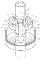
- FIG. 10 is a sectional view taken along line cc in FIG. It is a fragmentary perspective view of the tensioner of 3rd Embodiment.
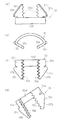
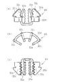
- (A), (b), (c), (d) is the front view, top view, back view, and perspective view of the locking piece used for 3rd Embodiment. It is sectional drawing in the case of manufacturing the locking piece of 3rd Embodiment.
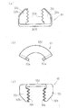
- (A), (b), (c) is the front view, top view, and rear view which show the locking piece which is difficult to press-mold.
- A), (b), (c) is the front view, top view, and rear view of another latching piece which can be used for 3rd Embodiment. It is a rear view which shows another 1st shape of a locking piece.
- the cylindrical member 1 is formed in a cylindrical shape in which a body portion 1a and a flange portion 1b on the rear end side (the upper end side in FIGS. 1 and 2) are connected to each other, and both end portions are opened.
- the flange portion 1b is in a state of being fixed to the engine body 200 by contacting the mounting surface 250 of the engine body 200.
- Locking teeth 1c are formed on the entire inner surface of the cylindrical member 1 including the body portion 1a and the flange portion 1b.
- the propulsion member 3 has a shaft shape including a large-diameter shaft portion 3a and a small-diameter shaft portion 3b connected to the rear end side (upper end side) of the large-diameter shaft portion 3a. Is formed.
- the propelling member 3 is entirely inserted into the cylindrical member 1 and can advance and retract in the axial direction with respect to the cylindrical member 1.
- a flange portion 3d is formed at the tip end portion (upper end portion) of the large-diameter shaft portion 3a, and the flange portion 3d contacts the chain guide 240 of the engine body 200.
- the large-diameter shaft portion 3 a of the propelling member 3 is formed to have an outer diameter slightly smaller than the inner diameter of the locking tooth 1 c on the inner surface of the cylindrical member 1. Thereby, the radial gap between the large-diameter shaft portion 3a of the propelling member 3 and the inner surface of the tubular member 1 can be reduced.
- Reference numeral 12 denotes a seal member disposed between the tip (lower end) of the cylindrical member 1 and the propelling member 3. By providing the seal member 12, the hydraulic pressure when the hydraulic pressure is applied to the cylindrical member 1 is shown. Sealability can be secured.
- the propulsion spring 4 is a coil spring.
- the propulsion spring 4 is externally inserted into the body portion 1a of the tubular member 1 in a state where the propulsion spring 4 is inserted between the flange portion 3d of the propulsion member 3 and the flange portion 1b of the tubular member 1. It is energizing to advance in the axial direction.
- the pressing spring 5 is formed by a coil spring provided between a pressing plate 9 attached to the small-diameter shaft portion 3 b of the propelling member 3 and a washer 6 disposed on the rear side (upper side) of the locking piece 2. Yes.
- the pressing spring 5 biases the locking piece 2 through the washer 6 so as to press it against the support surface 3 c of the propelling member 3.
- the locking piece 2 is pressed against the support surface 3c of the propelling member 3, and the locking piece 2 is biased so as to move in the diameter expansion direction.
- the engagement tooth 21 of the engagement piece 2 and the engagement tooth 1c of the tubular member 1 are in an engaged state in which backlash without backlash is reduced.
- the presser plate 9 is prevented from coming off from the small diameter shaft portion 3 b of the propelling member 3 by a C ring 10.
- the locking piece 2 includes a load receiving portion 22, a locking tooth forming portion 23, and a connecting portion 24.
- the locking tooth forming portion 23 has a two-row plate shape, and the two plate-shaped locking tooth forming portions 23 are integrally connected by a connecting portion 24.
- Locking teeth 21 are formed on the respective front end surfaces of the two plate-shaped locking tooth forming portions 23. As described above, the locking teeth 21 are engaged with and engaged with the locking teeth 1 c of the tubular member 1.
- the connecting portion 24 connects the locking tooth forming portion 23 in a plate shape. As described above, when the locking tooth forming portion 23 (locking tooth 21) is connected by the connecting portion 24, the structure has high torsional rigidity and improved mechanical strength.
- the propelling member 3 moves in the direction of diameter reduction along the support surface 3 c of the propelling member 3 in the advancing direction. Since the teeth 21 get over the locking teeth 1c of the cylindrical member 1, the propulsion member 3 can smoothly advance.
- the propelling member 3 moves backward, the locking piece 2 is pressed against the support surface 3c and moves in the diameter increasing direction, so that the locking tooth 21 engages with the locking tooth 1c of the tubular member 1. Thereby, the retreat of the propelling member 3 is locked.
- the locking piece 2 is rotatable with respect to the cylindrical member 1 and the propelling member 3, the locking piece 2 rotates when the propelling member 3 receives a load from the engine.
- the stop piece 2 moves backward with respect to the tubular member 1 in an engaged state with the tubular member 1. For this reason, the propelling member 3 can return and operate. Therefore, even when the engine becomes hot and the timing chain 230 is stuck, it is possible to prevent overload.
- the locking piece 2 can be reduced in weight by forming the locking piece 2 by pressing a plate-like member.
- the locking piece 2 lightweight, it is possible to improve the followability to high-frequency vibrations from the engine. And the followability with respect to the high frequency vibration from an engine becomes high, and the load of the press spring 5 which presses the locking piece 2 against the propulsion member 3 can also be reduced.
- FIG. 5 is a graph in which the vibration from the engine is plotted on the horizontal axis, and the thrust of the propelling member 3 required to follow the vibration is plotted on the vertical axis.
- the graph of FIG. 5 shows that the diameter of the large-diameter shaft portion 3a in the propulsion member 3 as shown in FIG. 6 is 16 mm, and the diameter of the small-diameter shaft portion 3b is 6 mm.
- a theoretical calculation was performed by constructing a tensioner to which a piece was attached and a push spring 5 was applied.
- a curved line M shows the measurement result of the locking piece 2 of this embodiment.
- the locking piece 2 As the locking piece 2, a plate material made of carbon steel and having a thickness of 1 mm was pressed to obtain an outer diameter of 16 mm, an inner diameter of 6 mm, a height of 10 mm, and a width of 8 mm.
- the locking piece 2 weighs 1.0 g.
- the curve L is the theoretical calculation result when the locking piece 2 having the same material, the same size, and the same number as the locking piece 2 of this embodiment, but having a solid structure is used.
- the locking piece on the curve L weighs 2.0 g.
- [Second Embodiment] 7 and 8 show a second embodiment of the present invention.
- the tensioner of this embodiment incorporates the adjustment member 14 with respect to the tensioner of 1st Embodiment, and the other structure is the same as that of 1st Embodiment.
- the adjusting member 14 has a structure having a top plate portion 15 and a plurality of (four) leg portions 16 depending on the top plate portion 15.
- a non-circular operation hole 17 such as a hexagon is formed in the central portion of the top plate portion 15.
- the plurality of leg portions 16 hang from the circumference of the top plate portion 15 in four equal positions. As shown in FIG. 8, the lower end portion of each leg portion 16 has a claw portion bent inward. 18 is formed.
- the adjustment member 14 is disposed on the locking piece 2 so that the leg portion 16 enters between the four locking pieces 2.
- claw part 18 is attached to the propelling member 3 in the state of coming off prevention by engaging with the groove part 3e formed in the lower part of the support surface 3c in the propelling member 3.
- the adjustment member 14 can rotate, but the movement in the axial direction is restricted.
- Such an adjusting member 14 is attached to the propelling member 3 to allow movement of the locking piece 2 in the radial direction and movement in the axial direction, but the rotation direction of the locking piece 2 with respect to a line orthogonal to the axial direction. Regulates movements.
- the adjustment member 14 integrates the movement of the locking piece 2 in the rotation direction by the leg portion 16 entering between the locking pieces 2.
- the tensioner of this embodiment is provided with a case 31, a plurality (two) of locking pieces 32, a shaft-like propelling member 33 inserted into the case 31, and the case 31.
- the holder 41 is provided.
- the case 31 is formed in a cylindrical shape with an opening in the axial direction, and the propelling member 33 is inserted so as to be able to move forward and backward.
- a propulsion spring 34 is provided in the case 31 to urge the propulsion member 33 in the advancing direction.
- the propulsion member 33 is formed with a flange-shaped spring receiving portion 33a at an axially intermediate portion, and the urging force of the propulsion spring 34 acts on the spring receiving portion 33a.
- Locking teeth 33 c are formed on the outer peripheral surface of the propelling member 33.
- the locking teeth 33c are formed on the outer peripheral surface on the front side of the spring receiving portion 33a.
- a shoe portion 33d that contacts the chain guide 240 is provided at the front end portion of the propelling member 33, and a screw hole 33e is formed in the axial direction at the rear end portion.
- the holder 41 is formed in a short cylindrical shape, and is disposed between the spring receiving portion 33a of the propelling member 33 and the stopper plate 36 on the front end side of the case 31.
- the cylindrical case 31 and the cylindrical holder 41 correspond to the cylindrical member 1 in the first and second embodiments.
- a conical support surface 42 is formed on the inner surface of the holder 41.
- the support surface 42 is formed on the spring receiving portion 33a side, and has a conical shape in which the diameter gradually increases toward the advancing direction of the propelling member 33.
- the holder 41 is urged by a holder spring 43 so as to be movable in the advancing direction of the propelling member 33.
- the locking piece 32 is supported on the support surface 42 by being provided in the holder 41 in contact with the support surface 42 of the holder 41.
- the locking piece 32 is urged by a pressing spring 35 in a direction in contact with the support surface 42 of the holder 41.
- the locking piece 32 is formed with locking teeth 32 a that engage with the locking teeth 33 c of the propulsion member 33.
- the locking piece 32 includes a load receiving portion 32b, a locking tooth forming portion 32c, and a connecting portion 32d.
- the locking tooth forming portions 32c are formed in two rows of plates, and the locking teeth 32a described above are formed on the front end surfaces of the respective locking tooth forming portions 32c.
- the two rows of locking tooth forming portions 32c are integrally connected by a connecting portion 32d.
- the connection part 32d connects the back surface part 32e of the locking tooth formation part 32c.
- the load receiving portion 32b is formed so as to be located on the opposite side to the back surface portion 32e in the locking tooth forming portion 32c. Accordingly, the load receiving portion 32b and the connecting portion 32d are provided at positions where they are not in direct contact so that the load received by the load receiving portion 32b is different from the direction in which the connecting portion 32d connects the locking tooth forming portion 32c. Yes. Thereby, since there is no undercut part in the latching piece 32 and there is no shape restriction
- the load receiving portion 32 b is formed in a conical shape having an inclination corresponding to the support surface 42 of the holder 41.
- the screw hole 33e of the propulsion member 33 is screwed into the holding bolt 45 on the rear end side of the case 2 to place the propulsion member 33 in a standby state.
- the case 31 is assembled to the engine body 200, and the screwing between the holding bolt 45 and the screw hole 33e is released.
- the propulsion member 33 is pushed out by the propulsion spring 34 and the shoe portion 33 d comes into contact with the chain guide 240.
- the propulsion member 33 advances by the urging force of the propulsion spring 34.
- the locking piece 32 moves in the diameter increasing direction, and the locking teeth 32a are released from the engagement with the locking teeth 33c of the propulsion member 33, so that the propulsion member 33 moves forward smoothly.
- the load receiving portion 32 b moves in the diameter reducing direction along the support surface 42 of the holder 41 by the urging force of the pressing spring 35, and the locking teeth 32 a move to the propelling member 33. Engaging with the locking teeth 33c. Thereby, the backward movement of the propelling member 33 is locked.
- the propulsion member is rotated by the rotation of the locking piece 32 when the propulsion member 33 receives a load from the engine. 33 moves backward. For this reason, even when the engine becomes hot and the timing chain 230 is stuck, it is possible to prevent overload.
- the locking piece 32 can be reduced in weight by forming the locking piece 32 by pressing the plate-like member. By making the locking piece 32 lighter, it is possible to improve the followability to high-frequency vibrations from the engine. And the followability with respect to the high frequency vibration from an engine becomes high, and the load of the press spring 35 which presses the locking piece 32 to the holder 41 can also be reduced.
- the locking piece 32 of this embodiment is easy to press because the load receiving portion 32b and the connecting portion 32d are not in direct contact with each other.
- FIG. 13 shows this pressing process, and the locking piece 32 can be produced without generating an undercut portion by pressing the punched original plate with a pair of press dies 51.
- the connecting portion 32d connects the upper surface of the locking tooth forming portion 32c. Even in this shape, since there is no undercut portion, press working is possible, and a plate-like member can be used as a material. This makes it possible to reduce the weight and improve the function of the tensioner.
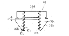
- the locking teeth 32a of the locking piece 62 in FIG. 16 are formed with the pitch ⁇ shifted.
- This locking piece 62 can be applied when the locking teeth 21 and 33c to be engaged with each other are screws having a circumferential phase, and the pitch ⁇ is shifted by the phase of the locking teeth on the other side.
- the cylindrical member 1 has both ends opened, a seal member 12 is mounted between the inner surface on the front end side and the propelling member 3, and a blind cover 73 is provided on the inner surface on the rear end side. It is mated.
- a hydraulic flow port 74 is opened, and a hydraulic pressure 71 from a hydraulic pressure source 70 provided on the engine body 200 side is filled into the tubular member 1 from the hydraulic flow port 74.
- the tubular member 1 is fixed via a bolt by a U-shaped clamp 77 in a state where the lower outer surface of the rear end portion is disposed in a shallow concave mounting groove 202 formed in the engine main body 200.
- a hydraulic circulation port 75 communicating with a hydraulic pressure source 70 provided on the engine body 200 side and a hydraulic circulation port 74 of the tubular member 1 are interposed through a seal member 79 fitted around the hydraulic circulation port 75.
- the U-shaped clamp 13 has a function of preventing the cylindrical member 1 that receives a load from the belt or chain guide 240 against which the propelling member 3 comes in contact from sliding and retreating.
- the inner wall 201 of the engine body 200 is provided with a relief portion 203 for the flange portion 3d of the propulsion member 3 and the belt or chain guide 240 along the propulsion direction of the propulsion member 3 continuously to the attachment groove 202. .
- a flat tooth having a pitch in the axial direction or a thread-like tooth having a pitch is used as the locking teeth 33c.
- a flat tooth having a pitch in the axial direction or a thread-like tooth having a pitch is used.
- the strength can be ensured
- the strength can be ensured and in the case of a screw-like tooth, the strength can be ensured and the smooth engagement can be performed.
- the number of the locking pieces 2, 32, 61, 62, 63, 64, 65 with respect to the tubular member and the propelling member can be one or three or more.
Landscapes
- Engineering & Computer Science (AREA)
- General Engineering & Computer Science (AREA)
- Mechanical Engineering (AREA)
- Devices For Conveying Motion By Means Of Endless Flexible Members (AREA)
Abstract
エンジンからの高周波の振動に対する良好な追従性を有すると共に、係止駒の加工を簡単に行うことができる係止駒の形状的な制約のないテンショナーを提供する。筒状部材1の内部で軸方向に進退移動可能となっている推進部材3と、推進部材3の進出方向への移動を付勢する推進ばね4と、筒状部材1の内面又は推進部材3の外面に形成された係止歯1cと、係止歯1cに係合する係止歯21が形成された係止駒2とを備える。係止駒2は、推進部材3が後退するときの荷重を受ける荷重受け部22と、係止歯21が形成される2列以上の係止歯形成部23と、係止歯形成部23を一体に接続する接続部24とを備え、筒状部材1及び推進部材3に対して回転可能となっている。
Description
本発明は、無端状のベルトやチェーンの張力を一定に保つために用いられるテンショナーに関する。
テンショナーは、例えば、自動車のエンジンに使用されるタイミングチェーンやタイミングベルトを所定の力で押しており、これらに伸びや緩みが生じた場合に、その張力を一定に保つように作用する。
図21は、テンショナー100を自動車のエンジン本体200に実装した状態を示す。エンジン本体200の内部には、一対のカムスプロケット210とクランクスプロケット220とが配置されており、これらのスプロケット210、220の間にタイミングチェーン230が無端状となって掛け渡されている。タイミングチェーン230の移動路上には、チェーンガイド240が揺動自在に配置されており、タイミングチェーン230はチェーンガイド240を摺動する。エンジン本体200には、取付面250が形成されており、テンショナー100は取付面250に形成された取付孔260に挿通されてボルト270により取付面250に固定される。この場合、エンジン本体200の内部には、図示しない潤滑用のオイルが封入されている。
図22は、特許文献1に記載された従来のテンショナー300を示す。軸方向に進退する軸状の推進部材310がケース370に挿入されている。推進部材310は、ケース370内に設けられた推進ばね340によってケース370から進出するように付勢されている。
ケース370内には、ホルダーばね360によって推進部材310の進出方向に付勢されたホルダー330が設けられ、このホルダー330に2つの係止駒320が支持されている。係止駒320は、中実のナットを割断した形状となっており、後側の外周面には、円錐状のカム斜面321が形成されている。これに対し、ホルダー330の内周面には、係止駒320のカム斜面321が接触するカム斜面331が形成されている。ホルダー330のカム斜面331は凹んだ円錐状に形成されるものである。係止駒320は、カム斜面321,331が接触した状態でホルダー330に支持される。350は、係止駒320をホルダー330に押し付けるための押圧ばねである。係止駒320の内周面には、係止歯323が形成されると共に、推進部材310の外周面には、係止駒320の係止歯323が噛み合って係合する係止歯313が形成されている。
このような構造では、推進部材310が推進ばね340によって進出方向に付勢されている。このとき、係止駒320は、拡径方向に移動して係止歯323と推進部材310の係止歯313との係合が解除されているため、推進部材310は進出が可能となっている。これに対し、推進部材310に後退方向への過負荷が作用すると、係止駒320は、押圧ばね350の付勢力によってカム斜面331に沿って縮径方向に移動して推進部材310と係合するため、推進部材310の後退がロックされる。これらの作動によって、タイミングチェーン230に張力を付与することができる。
テンショナーにおいては、エンジンからの高周波の強力な振動を受けるため、推進部材310及び係止駒320は、振動に対する追従性が高いことが好ましい。この追従性を向上させるためには、軽量化することが好ましい。しかしながら、従来のテンショナーにおける係止駒320が中実のナットを割断して形成されているため、係止駒320の軽量化が難しく、振動に対する良好な追従性を得ることができない問題がある。
また、中実のナットを割断して形成される係止駒320は、切削又は焼結によって作製される。しかし、切削加工では、ナットを分割する際にバリが発生して、その除去が必要となると共に、切削加工のサイクルタイムが長くなる。一方、焼結加工では、成形可能な形状的な制約が加わり、テーパ形状、半円形状等への加工が難しいと共に、係止歯の成形が難しい。又、材料密度が不均一となり、欠肉を生じて十分な強度を得ることができない。さらに、薄板板金による加工によって係止駒320を加工する場合には、アンダーカット部分の成形が困難となり、量産性に欠ける問題がある。
本発明は、このような問題点を考慮してなされたものであり、エンジンからの高周波の振動に対する良好な追従性を有すると共に、係止駒の加工を簡単に行うことができ、しかも係止駒の形状的な制約のないテンショナーを提供することを目的とする。又、本発明は、推進部材がエンジンから高負荷を受けたとき、推進部材が円滑に戻り作動して過負荷防止を行うことが可能なテンショナーを提供することを目的とする。
請求項1記載の発明のテンショナーは、筒状部材の内部で軸方向に進退移動可能となっている推進部材と、前記推進部材の進出方向への移動を付勢する推進ばねと、前記筒状部材の内面又は前記推進部材の外面に形成された係止歯と、前記係止歯に係合する係止歯が形成された係止駒とを備え、前記係止駒の係止歯が前記筒状部材の係止歯又は推進部材の係止歯に係合した状態で前記筒状部材と推進部材との間に配置されて推進部材の後退方向へのロックを行うテンショナーであって、前記係止駒は、前記推進部材が後退するときの荷重を受ける荷重受け部と、前記係止歯が形成される2列以上の係止歯形成部と、この係止歯形成部を一体に接続する接続部とを備え、前記筒状部材及び推進部材に対して回転可能となっていることを特徴とする。
請求項2記載の発明は、請求項1記載のテンショナーであって、前記荷重受け部が受ける荷重方向と、前記接続部が前記係止歯形成部を接続する接続方向とが異なった方向となるように前記荷重受け部と接続部とが直接に接しない位置に設けられていることを特徴とする。
請求項3記載の発明は、請求項1記載のテンショナーであって、前記荷重受け部が前記推進部材の推進方向に沿って傾斜した円錐状となっており、前記推進部材又は筒状部材に前記荷重受け部と接触する円錐状の支持面が形成されていることを特徴とする。
請求項4記載の発明は、請求項1記載のテンショナーであって、前記係止駒の前記推進部材の推進方向への動き及び前記推進方向と交差した径方向への動きを許容可能な調整部材が前記筒状部材の内部に回転可能に設けられていることを特徴とする。
請求項5記載の発明は、請求項1記載のテンショナーであって、前記係止駒は、板状部材のプレス加工により成形されていることを特徴とする。
請求項6記載の発明は、請求項1記載のテンショナーであって、前記推進部材を進出させる油圧を作用させる油圧源がさらに設けられていることを特徴とする。
本発明によれば、係止駒を荷重受け部、係止歯形成部及び接続部によって形成しているため、係止駒を板状部材によって成形することができ、係止駒を軽量とすることができる。このため、エンジンに対する追従性が良好となり、しかも加工が簡単となる。又、係止駒が筒状部材及び推進部材に対して回転可能となっているため、推進部材がエンジンからの荷重を受けたとき、係止駒が筒状部材との係合状態で後退でき、推進部材が戻り作動して過負荷防止が可能となる。
[第1実施形態]
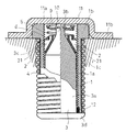
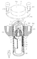
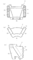
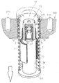
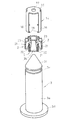
図1~図4は、本発明の第1実施形態を示し、図1は、この実施形態のテンショナーの縦断面図、図2は、エンジン本体に取り付けた状態の斜視図、図3は、係止駒と推進部材との関係を示す斜視図、図4は、係止駒の正面図、平面図、斜視図である。
図1~図4は、本発明の第1実施形態を示し、図1は、この実施形態のテンショナーの縦断面図、図2は、エンジン本体に取り付けた状態の斜視図、図3は、係止駒と推進部材との関係を示す斜視図、図4は、係止駒の正面図、平面図、斜視図である。
この実施形態のテンショナーは、筒状部材1、係止駒2、推進部材3、推進ばね4、押圧ばね5を備えている。
筒状部材1は、胴部1a及び後端側(図1及び図2においては上端側)のフランジ部1bが連設され、両端部が開口した円筒状に形成されている。フランジ部1bは、エンジン本体200の取付面250に当接することによりエンジン本体200に固定された状態となる。胴部1a及びフランジ部1bを含む筒状部材1の内面の全体には係止歯1cが形成されている。
係止駒2は、筒状部材1の係止歯1cに係合した状態で筒状部材1の内部に配置される。係止駒2は、筒状部材1内面の係止歯1cに係合する係止歯21が形成されており、係止歯21が係止歯1cに噛み合って係合した状態で筒状部材1に対して回転可能となっている。係止駒2は、後述する推進部材3の支持面3cに当接することにより、支持面3cに支持される。この実施形態においては、図2に示すように、係止駒2が推進部材3の周方向に複数(4つ)が支持されるものである。
図1~図3に示すように、推進部材3は、大径軸部3aと、大径軸部3aの後端側(上端側)に連設された小径軸部3bとを備えた軸状に形成されている。推進部材3は、全体が筒状部材1の内部に挿入され、筒状部材1に対して軸方向に進退可能となっている。大径軸部3aの先端部(上端部)には、フランジ部3dが形成されており、フランジ部3dがエンジン本体200のチェーンガイド240に当接する。推進部材3の大径軸部3aは、筒状部材1内面の係止歯1cの内径よりわずかに小さな外径に形成される。これにより、推進部材3の大径軸部3aと筒状部材1の内面との間の径方向の隙間を小さくすることができる。12は、筒状部材1の先端(下端)と推進部材3との間に配置されたシール部材であり、シール部材12を設けることにより、筒状部材1内に油圧を作用させる場合の油圧のシール性を確保することができる。
推進部材3における大径軸部3aと小径軸部3bとの境界部分には、支持面3cが形成されている。支持面3cは、推進部材3の進出方向に向かって径が漸次拡径する円錐状となっている。支持面3cは、円錐状に形成されており、係止駒2を回転可能に支持するものである。
推進ばね4は、コイルばねが使用されている。推進ばね4は、推進部材3のフランジ部3dと、筒状部材1のフランジ部1bとの間に挿入された状態で筒状部材1の胴部1aに外挿されており、推進部材3が軸方向に進出するように付勢している。
押圧ばね5は、推進部材3の小径軸部3bに取り付けられた押えプレート9及び係止駒2の後側(上側)に配置されたワッシャ6との間に設けられたコイルばねによって形成されている。押圧ばね5は、ワッシャ6を介して係止駒2を推進部材3の支持面3cに押圧するように付勢するものである。この付勢により、係止駒2は推進部材3の支持面3cに押圧され、係止駒2は拡径方向に移動するように付勢される。これにより、係止駒2の係止歯21と、筒状部材1の係止歯1cとががたつきのないバックラッシュを低減した係合状態となる。なお、押えプレート9はCリング10によって推進部材3の小径軸部3bからの外れ止めがなされている。
この実施形態においては、取付蓋11が用いられる。取付蓋11は、蓋本体11aと、蓋本体11aの外周側のフランジ部11bとによって形成されている。取付蓋11は、筒状部材1及び推進部材3をエンジン本体200に固定するためのものであり、筒状部材1のフランジ部1b及び推進部材3の小径軸部3bの後側(上側)に被せられる。そして、図2に示すように、フランジ部11bにボルト270を貫通させ、ボルト270をエンジン本体200のボルト孔271に螺合させることによりエンジン本体200の取付面250に固定される。この固定により、蓋本体11aが筒状部材1、推進部材3、推進ばね4をエンジン本体200に装着する。
図4に示すように、係止駒2は、荷重受け部22と、係止歯形成部23と、接続部24とを備えている。係止歯形成部23は、2列の板状となっており、板状2列の係止歯形成部23が接続部24によって一体に接続されている。板状2列の係止歯形成部23のそれぞれの先端面には、係止歯21が形成される。上述したように係止歯21は、筒状部材1の係止歯1cに噛み合って係合する。接続部24は、板状となった状態で係止歯形成部23を接続する。このように係止歯形成部23(係止歯21)が接続部24によって接続されることにより、ねじり剛性が高く、機械的強度も向上した構造となる。
荷重受け部22は、推進部材3の支持面に相応した円錐状に形成されている。すなわち、荷重受け部22は、推進部材3の推進方向に沿って傾斜した円錐状となっており、推進部材3の支持面3cに面接触する。この面接触によって荷重受け部22は、推進部材3が後退するときの荷重を受ける。荷重受け部22は円錐状に形成されており、この荷重受け部22が同様に円錐状に形成されている支持面3cに接触することにより、係止駒2が推進部材3に対して回転可能となっている。このことにより、係止駒2は、推進部材3及び筒状部材1に対して回転可能となっており、係止駒2は、推進部材3及び筒状部材1に対して回転方向に独立して動くことができる。
図3及び図4に示すように、係止駒2には、アンダーカット部分がなく、形状的な制約がないため、係止駒2を板状部材のプレス加工によって作製することができる。このため、係止駒2を切削や焼結によって作製する必要がなく、係止駒2の作製が容易となり、量産性に優れたものとなる。又、係止駒2が板状部材のプレスによって作製されることから、中実な構造とする必要がなく、係止駒2の軽量化及び安価での提供が可能となる。
以上のテンショナーにおいては、係止駒2が押圧ばね5によって付勢されているため、推進部材3の進出方向には、推進部材3の支持面3cに沿って縮径方向に移動し、係止歯21が筒状部材1の係止歯1cを乗り越えるため、推進部材3の円滑な進出が可能となる。推進部材3が後退する場合には、係止駒2が支持面3cに押圧されて拡径方向に移動するため、係止歯21が筒状部材1の係止歯1cに係合する。これにより、推進部材3の後退がロックされる。
又、係止駒2が筒状部材1及び推進部材3に対して回転可能となっているため、エンジンからの荷重を推進部材3が受けたときに係止駒2が回転することにより、係止駒2は筒状部材1との係合状態で筒状部材1に対して後退する。このため、推進部材3が戻り作動することができる。従って、エンジンが高温になり、タイミングチェーン230が張り込んだ場合でも、過負荷防止を行うことができる。
さらに、係止駒2が板状部材のプレス加工によって成形されることにより、係止駒2を軽量とすることができる。係止駒2が軽量となることにより、エンジンからの高周波の振動に対する追従性を高くできる。そして、エンジンからの高周波の振動に対する追従性が高くなることにより、係止駒2を推進部材3に押し付ける押圧ばね5の荷重も低減することができる。
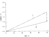
図5は、エンジンからの振動を横軸にプロットし、その振動に追従するために必要な推進部材3の推力を縦軸にプロットしたグラフである。図5のグラフは、図6に示すような推進部材3における大径軸部3aの直径を16mm、小径軸部3bの直径を6mmとし、この推進部材3の支持面3cに2個の係止駒を取り付け、押しばね5を作用させたテンショナーを構成して理論計算を行ったものである。曲線Mは、この実施形態の係止駒2の測定結果を示す。係止駒2としては、炭素鋼からなる板厚1mmの板材をプレス加工して、外径16mm、内径6mm、高さ10mm、幅8mmとしたものを用いた。この係止駒2が1.0gの重さである。曲線Lは、この実施形態の係止駒2と同材料、同寸法及び同数としたが、中実構造となっている係止駒2を用いた場合の理論計算結果である。曲線Lにおける係止駒は2.0gの重さである。
図5に示すように、板材のプレス加工によって作製されたこの実施形態の係止駒においては、中実の係止駒よりも振動に対して小さな推力となっており、高周波の振動に対する追従性が良好であることがわかる。
[第2実施形態]
図7及び図8は、本発明の第2実施形態を示す。この実施形態のテンショナーは、第1実施形態のテンショナーに対し、調整部材14を組み込んだものであり、その他の構成は第1実施形態と同様となっている。
図7及び図8は、本発明の第2実施形態を示す。この実施形態のテンショナーは、第1実施形態のテンショナーに対し、調整部材14を組み込んだものであり、その他の構成は第1実施形態と同様となっている。
調整部材14は、天板部15と、天板部15垂下する複数(4つ)の脚部16とを有した構造となっている。天板部15の中央部分には、6角等の非円形の操作孔17が形成されている。複数の脚部16は、天板部15の円周の4等分位置から垂下しており、図8に示すように、それぞれの脚部16の下端部には、内側に折り曲げられた爪部18が形成されている。
図7に示すように、調整部材14は、脚部16が4つの係止駒2の間に入り込むように係止駒2上に配置される。そして、爪部18が推進部材3における支持面3cの下部に形成された溝部3eに係合することにより推進部材3に外れ止め状態で取り付けられる。爪部18が溝部3eに係合することにより、調整部材14は回転が可能であるが、軸方向への動きが規制される。このような調整部材14は、推進部材3に取り付けられることにより、係止駒2の径方向の移動及び軸方向の移動を許容するが、軸方向と直交する線に対する係止駒2の回転方向の動きは規制する。又、調整部材14は、脚部16が係止駒2の間に入り込むことにより、係止駒2の回転方向への動きを一体化する。
このような調整部材14において、その操作孔17にレンチ等の工具を差し込んで調整部材14を回転させると、その係止歯21が筒状部材1の係止歯1cに係合している係止駒2は同方向に回転して軸方向に進退移動する。これにより、推進部材3が軸方向へ移動可能となる。従って、推進部材3を後退させてタイミングチェーン230を緩めたり、推進部材3を前進させてタイミングチェーン230に張りを与えたりする操作が可能となる。これにより、メンテナンスに便利となるメリットがある。その他の効果は、第1実施形態と同様である。
[第3実施形態]
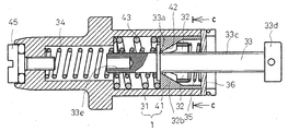
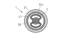
図9~図13は、本発明の第3実施形態であり、図9~図11は、この実施形態のテンショナーを示す。
図9~図13は、本発明の第3実施形態であり、図9~図11は、この実施形態のテンショナーを示す。
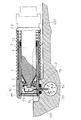
図9に示すように、この実施形態のテンショナーは、ケース31と、複数(2つ)の係止駒32と、ケース31内に挿入された軸状の推進部材33と、ケース31内に設けられたホルダー41とを備えている。
ケース31は、軸方向の先端部が開口された筒形状に形成されており、推進部材33が進退移動可能に挿入される。推進部材33を進出方向に付勢するため、推進ばね34がケース31内に設けられている。推進部材33は、軸方向の中間部分にフランジ状のばね受け部33aが形成されており、ばね受け部33aに推進ばね34の付勢力が作用するようになっている。
推進部材33の外周面には、係止歯33cが形成されている。係止歯33cは、ばね受け部33aよりも前方側の外周面に形成されるものである。推進部材33の先端部には、チェーンガイド240に当接するシュー部33dが設けられ、後端部にはねじ孔33eが軸方向に形成されている。
ホルダー41は、短尺の筒状に形成されており、推進部材33のばね受け部33aとケース31の先端側のストッパプレート36との間に配置されている。この実施形態において、筒状のケース31及び筒状のホルダー41は、第1実施形態と第2実施形態における筒状部材1に相当するものである。ホルダー41の内面には、円錐状の支持面42が形成されている。支持面42は、ばね受け部33a側に形成されるものであり、推進部材33の進出方向に向かって径が漸次拡径する円錐状となっている。ホルダー41は、ホルダーばね43により、推進部材33の進出方向に移動可能に付勢されている。
係止駒32は、ホルダー41の支持面42と接触した状態でホルダー41内に設けられることにより支持面42に支持されている。係止駒32は、押圧ばね35によってホルダー41の支持面42と接触する方向に付勢されている。又、係止駒32は、推進部材33の係止歯33cと係合する係止歯32aが形成されている。
図11及び図12に示すように、係止駒32は、荷重受け部32bと、係止歯形成部32cと、接続部32dとを備えている。係止歯形成部32cは、2列の板状となっており、それぞれの係止歯形成部32cの先端面には、上述した係止歯32aが形成されている。2列の係止歯形成部32cは、接続部32dにより一体に接続されている。接続部32dは、係止歯形成部32cの背面部32eを接続するものである。このような係止駒32は、ホルダー41に対して回転可能となっていると共に、推進部材33に対して回転可能となっている。
荷重受け部32bは、係止歯形成部32cにおける背面部32eとの反対側に位置するように形成されている。従って、荷重受け部32bと接続部32dとは、荷重受け部32bが受ける荷重と、接続部32dが係止歯形成部32cを接続する方向とが異なるように直接に接しない位置に設けられている。これにより、係止駒32にはアンダーカット部分がなく、形状的な制約がないため、係止駒32を板状部材のプレス加工によって作製することができる。この場合、荷重受け部32bは、ホルダー41の支持面42に対応する傾斜を有した円錐状に形成されている。
このようなテンショナーにおいては、推進部材33のねじ孔33eをケース2の後端側の保持ボルト45に螺合させて推進部材33を待機状態とする。この状態で、ケース31をエンジン本体200に組み付け、保持ボルト45とねじ孔33eとの螺合を解除する。これにより、推進ばね34によって推進部材33が押し出されてそのシュー部33dがチェーンガイド240に当接する。
このような構造では、推進部材33が推進ばね34の付勢力により進出する。このとき、係止駒32は、拡径方向に移動して係止歯32aが推進部材33の係止歯33cとの係合から解除されているため、推進部材33が円滑に進出する。推進部材33に後退方向への過負荷が作用すると、押圧ばね35の付勢力によって荷重受け部32bがホルダー41の支持面42に沿って縮径方向に移動し、係止歯32aが推進部材33の係止歯33cと係合する。これにより、推進部材33の後退がロックされる。
ここで、係止駒32がホルダー41及び推進部材33に対して回転可能となっているため、エンジンからの荷重を推進部材33が受けたときに係止駒32が回転することにより、推進部材33が後退する。このため、エンジンが高温になり、タイミングチェーン230が張り込んだ場合でも、過負荷防止を行うことができる。
上述したように、係止駒32が板状部材のプレス加工によって成形されることにより、係止駒32を軽量とすることができる。係止駒32が軽量となることにより、エンジンからの高周波の振動に対する追従性を高くできる。そして、エンジンからの高周波の振動に対する追従性が高くなることにより、係止駒32をホルダー41に押し付ける押圧ばね35の荷重も低減することができる。
図14は、荷重受け部32bと接続部32dとが直接に接続された構造の係止駒420を示す。すなわち、荷重受け部32bと接続部32dとが連設部421によって直接に接続されるものである。図14の係止駒420においては、連設部421が係止歯形成部32cの内側で囲まれるため、アンダーカット形状となり、プレス加工が困難となる。一方、図14の係止駒420を絞り加工する場合には、材料の複雑な引っ張り合いによって係止歯32aが変形する。このため、推進部材33との係止歯33cとの係合が難しくなる。図14において、Qは引っ張り合いの方向を示す。
図14の係止駒420に対し、この実施形態の係止駒32は、荷重受け部32bと接続部32dとが直接に接していないため、プレス加工が容易である。図13は、このプレス加工を示し、打ち抜き原板を一対のプレス型51によってプレスすることにより、アンダーカット部分を発生させることなく係止駒32を作製することができる。
図15~図19は、図9に示すテンショナーに用いることができる係止駒の別例をそれぞれ示す。図15の係止駒61においては、接続部32dが係止歯形成部32cの上面を接続している。この形状においても、アンダーカット部分がないため、プレス加工が可能であり、材料として板状部材を用いることができ、これにより軽量化が可能となり、テンショナーの機能を向上させることができる。
図16の係止駒62の係止歯32aがピッチαをずらして形成されている。この係止駒62は、係合相手となる係止歯21、33cが周方向の位相があるねじの場合に適用することができ、ピッチαは、相手側の係止歯の位相分ずれるように設定される。
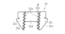
図17の係止駒63は、係止歯32aがそれぞれの係止歯形成部32cに一つ形成されたものである。図18の係止駒64は、係止歯32aがβだけ斜めに傾いて形成されたものであり、ねじの螺旋に合わせることが可能となっている。図19の係止駒65は、係止歯形成部32cが4列設けられたものである。以上の係止歯32aの形状や歯数、歯列は適宜変更できるものである。
[第4実施形態]
図20は、本発明の第4実施形態を示す。この実施形態のテンショナーは、第1実施形態のテンショナーに油圧源70が接続された構造となっており、油圧源70の油圧71が推進部材3の進出方向に作用する。
図20は、本発明の第4実施形態を示す。この実施形態のテンショナーは、第1実施形態のテンショナーに油圧源70が接続された構造となっており、油圧源70の油圧71が推進部材3の進出方向に作用する。
図20に示すように、筒状部材1は、両端部が開口され、先端側の内面と推進部材3との間にシール部材12が装着されると共に、後端側の内面に盲蓋73が嵌合している。筒状部材1の後端側には、油圧流通口74が開設されており、エンジン本体200側に設けられた油圧源70からの油圧71が油圧流通口74から筒状部材1内部に充填される。
シール部材12は、筒状部材1内の油圧をシールするとともに推進部材3の抜け止めを行う。従って、推進部材3が進出し続けると、推進部材3の支持面3cに組み込まれている係止駒2の係止歯21がシール部材12に突き当たることにより推進部材3の進出が制止される。
筒状部材1は、後端部の下方外面がエンジン本体200の穿設された浅い凹状の取付け溝202内に配置された状態でU字型クランプ77によりボルトを介して固定される。このとき、エンジン本体200側に設けられた油圧源70に連通する油圧流通口75と筒状部材1の油圧流通口74とが油圧流通口75の周囲に嵌着されたシール部材79を介して対向して一致するように配置される。
U字型クランプ13は、推進部材3が当接するベルト又はチェーンガイド240からの負荷を受けた筒状部材1がスライドして後退するのを阻止する機能を有する。
U字型クランプ13は、推進部材3が当接するベルト又はチェーンガイド240からの負荷を受けた筒状部材1がスライドして後退するのを阻止する機能を有する。
なお、エンジン本体200の内壁201には、取付け溝202に連続して、推進部材3の推進方向に沿って推進部材3のフランジ部3d及びベルト又はチェーンガイド240に対する逃げ部203が設けられている。
この実施形態においても、係止駒2は、第1実施形態と同様に形成される。これにより、第1実施形態と同様な効果を有している。これに加えて、筒状部材1内の推進部材3の推進方向に油圧71を作用させることにより推進部材3の推進力がアップするため、これに相応して圧縮力を低く設定した小形の推進ばね4を用いることができる。また、油圧油が粘性を有しているため、推進部材3及び係止駒2等の可動部材の作動に対して油圧油の粘性抵抗によるダンピング効果及び潤滑効果が付加される。このため、推進部材3の進退時の振幅を安定的に抑制する効果が高められるとともに、これら可動部材の摩耗を抑制することにより耐久性を向上させることができる。このような実施形態のテンショナーは、比較的軽負荷運転を行う小型エンジンから中負荷運転を行う中型エンジンに亘って適用し得る設計の自由度がある。
本発明においては、第1、第2、第4実施形態における筒状部材1の係止歯1c及びこれに係合する係止駒21の係止歯21、第3実施形態における推進部材3の係止歯33c及びこれに係合する係止駒32,61,62,63,64,65の係止歯32aとして、軸方向のピッチが零の平歯又はピッチを有するねじ状歯を用いることができる。平歯の場合には、強度を確保でき、ねじ状歯では、強度を確保し、しかも円滑な噛み込み係合を行うことができる。又、筒状部材及び推進部材に対する係止駒2,32,61,62,63,64,65の個数は、1つ或いは3つ以上とすることが可能である。
1:筒状部材
1c,22:係止歯
2,32,61,62,63,64,65:係止駒
3,33:推進部材
3c:支持面
4,34:推進ばね
5、35:押圧ばね
14:調整部材
22:荷重受け部
23:係止歯形成部
24:接続部
1c,22:係止歯
2,32,61,62,63,64,65:係止駒
3,33:推進部材
3c:支持面
4,34:推進ばね
5、35:押圧ばね
14:調整部材
22:荷重受け部
23:係止歯形成部
24:接続部
Claims (6)
- 筒状部材の内部で軸方向に進退移動可能となっている推進部材と、前記推進部材の進出方向への移動を付勢する推進ばねと、前記筒状部材の内面又は前記推進部材の外面に形成された係止歯と、前記係止歯に係合する係止歯が形成された係止駒とを備え、前記係止駒の係止歯が前記筒状部材の係止歯又は推進部材の係止歯に係合した状態で前記筒状部材と推進部材との間に配置されて推進部材の後退方向へのロックを行うテンショナーであって、
前記係止駒は、前記推進部材が後退するときの荷重を受ける荷重受け部と、前記係止歯が形成される2列以上の係止歯形成部と、この係止歯形成部を一体に接続する接続部とを備え、前記筒状部材及び推進部材に対して回転可能となっていることを特徴とするテンショナー。 - 前記荷重受け部が受ける荷重方向と、前記接続部が前記係止歯形成部を接続する接続方向とが異なった方向となるように前記荷重受け部と接続部とが直接に接しない位置に設けられていることを特徴とする請求項1記載のテンショナー。
- 前記荷重受け部が前記推進部材の推進方向に沿って傾斜した円錐状となっており、前記推進部材又は筒状部材に前記荷重受け部と接触する円錐状の支持面が形成されていることを特徴とする請求項1記載のテンショナー。
- 前記係止駒の前記推進部材の推進方向への動き及び前記推進方向と交差した径方向への動きを許容可能な調整部材が前記筒状部材の内部に回転可能に設けられていることを特徴とする請求項1記載のテンショナー。
- 前記係止駒は、板状部材のプレス加工により成形されていることを特徴とする請求項1記載のテンショナー。
- 前記推進部材を進出させる油圧を作用させる油圧源がさらに設けられていることを特徴とする請求項1記載のテンショナー。
Priority Applications (2)
| Application Number | Priority Date | Filing Date | Title |
|---|---|---|---|
| PCT/JP2011/062634 WO2012164707A1 (ja) | 2011-06-01 | 2011-06-01 | テンショナー |
| CN201180071300.3A CN103562595B (zh) | 2011-06-01 | 2011-06-01 | 张紧器 |
Applications Claiming Priority (1)
| Application Number | Priority Date | Filing Date | Title |
|---|---|---|---|
| PCT/JP2011/062634 WO2012164707A1 (ja) | 2011-06-01 | 2011-06-01 | テンショナー |
Publications (1)
| Publication Number | Publication Date |
|---|---|
| WO2012164707A1 true WO2012164707A1 (ja) | 2012-12-06 |
Family
ID=47258592
Family Applications (1)
| Application Number | Title | Priority Date | Filing Date |
|---|---|---|---|
| PCT/JP2011/062634 Ceased WO2012164707A1 (ja) | 2011-06-01 | 2011-06-01 | テンショナー |
Country Status (2)
| Country | Link |
|---|---|
| CN (1) | CN103562595B (ja) |
| WO (1) | WO2012164707A1 (ja) |
Cited By (2)
| Publication number | Priority date | Publication date | Assignee | Title |
|---|---|---|---|---|
| WO2016021567A1 (ja) * | 2014-08-08 | 2016-02-11 | 日本発條株式会社 | 荷重付加装置 |
| CN113882604A (zh) * | 2021-10-29 | 2022-01-04 | 浙江亚厦装饰股份有限公司 | 一种卡装的装配式楼梯面板安装系统及其安装方法 |
Families Citing this family (1)
| Publication number | Priority date | Publication date | Assignee | Title |
|---|---|---|---|---|
| CN108644328A (zh) * | 2018-05-28 | 2018-10-12 | 重庆隆鑫发动机有限公司 | 正时用张紧装置及发动机 |
Citations (3)
| Publication number | Priority date | Publication date | Assignee | Title |
|---|---|---|---|---|
| JPH08152051A (ja) * | 1994-09-26 | 1996-06-11 | Nhk Spring Co Ltd | 推進力付与装置 |
| JP2004190842A (ja) * | 2002-12-13 | 2004-07-08 | Tsubakimoto Chain Co | チェーン張力付与装置 |
| JP2010084878A (ja) * | 2008-10-01 | 2010-04-15 | Nhk Spring Co Ltd | テンショナー |
Family Cites Families (3)
| Publication number | Priority date | Publication date | Assignee | Title |
|---|---|---|---|---|
| CN1083956C (zh) * | 1995-12-21 | 2002-05-01 | 本田技研工业株式会社 | 推进力赋予装置 |
| JP4835915B2 (ja) * | 2005-09-30 | 2011-12-14 | 日本発條株式会社 | テンショナー |
| JP5157013B2 (ja) * | 2008-10-01 | 2013-03-06 | 日本発條株式会社 | テンショナー |
-
2011
- 2011-06-01 CN CN201180071300.3A patent/CN103562595B/zh not_active Expired - Fee Related
- 2011-06-01 WO PCT/JP2011/062634 patent/WO2012164707A1/ja not_active Ceased
Patent Citations (3)
| Publication number | Priority date | Publication date | Assignee | Title |
|---|---|---|---|---|
| JPH08152051A (ja) * | 1994-09-26 | 1996-06-11 | Nhk Spring Co Ltd | 推進力付与装置 |
| JP2004190842A (ja) * | 2002-12-13 | 2004-07-08 | Tsubakimoto Chain Co | チェーン張力付与装置 |
| JP2010084878A (ja) * | 2008-10-01 | 2010-04-15 | Nhk Spring Co Ltd | テンショナー |
Cited By (2)
| Publication number | Priority date | Publication date | Assignee | Title |
|---|---|---|---|---|
| WO2016021567A1 (ja) * | 2014-08-08 | 2016-02-11 | 日本発條株式会社 | 荷重付加装置 |
| CN113882604A (zh) * | 2021-10-29 | 2022-01-04 | 浙江亚厦装饰股份有限公司 | 一种卡装的装配式楼梯面板安装系统及其安装方法 |
Also Published As
| Publication number | Publication date |
|---|---|
| CN103562595B (zh) | 2016-07-06 |
| CN103562595A (zh) | 2014-02-05 |
Similar Documents
| Publication | Publication Date | Title |
|---|---|---|
| JP6107920B2 (ja) | 直動アクチュエータの製造方法 | |
| FR3026454A1 (fr) | Mecanisme de vis a rouleaux et procede de fabrication associe | |
| RU2514319C2 (ru) | Усовершенствованное прессовое соединение корпуса зубчатой рейки | |
| JP5157013B2 (ja) | テンショナー | |
| WO2012164707A1 (ja) | テンショナー | |
| EP2315967B1 (en) | Clip-type tensioner | |
| JP5364930B2 (ja) | テンショナー | |
| CN1190296C (zh) | 滚珠丝杠及使用它的直线运动装置 | |
| JP5897410B2 (ja) | テンショナ | |
| WO2016021566A1 (ja) | 荷重付加装置 | |
| JP4680736B2 (ja) | テンショナリフタ | |
| CN112045579B (zh) | 用于对物体进行夹紧的夹紧装置 | |
| JP2007057026A (ja) | 回転−直線運動変換装置及びその組付け方法 | |
| CN105642942B (zh) | 一种镗削加工三轴联动机械臂 | |
| JP5250889B2 (ja) | テンショナー | |
| CN104145138A (zh) | 行星滚子螺纹传动装置和用于制造行星滚子螺纹传动装置的方法 | |
| JP2007120537A (ja) | オートテンショナ | |
| JP3201198U (ja) | テレスコピック接合部構造 | |
| JP6317331B2 (ja) | テンショナー | |
| CN105665763B (zh) | 一种深孔镗削机械臂切削段结构 | |
| JP4903403B2 (ja) | オートテンショナ | |
| JP5381587B2 (ja) | 工作機械のタレット装置 | |
| RU80525U1 (ru) | Роликовинтовая передача | |
| CN200981161Y (zh) | 立式搪铣床的横式铣头自动换刀机构 | |
| JP2009216212A (ja) | チェーンテンショナ |
Legal Events
| Date | Code | Title | Description |
|---|---|---|---|
| 121 | Ep: the epo has been informed by wipo that ep was designated in this application |
Ref document number: 11866505 Country of ref document: EP Kind code of ref document: A1 |
|
| NENP | Non-entry into the national phase |
Ref country code: DE |
|
| 122 | Ep: pct application non-entry in european phase |
Ref document number: 11866505 Country of ref document: EP Kind code of ref document: A1 |
|
| NENP | Non-entry into the national phase |
Ref country code: JP |