WO2012161127A1 - 筒内噴射式内燃機関の制御装置 - Google Patents
筒内噴射式内燃機関の制御装置 Download PDFInfo
- Publication number
- WO2012161127A1 WO2012161127A1 PCT/JP2012/062834 JP2012062834W WO2012161127A1 WO 2012161127 A1 WO2012161127 A1 WO 2012161127A1 JP 2012062834 W JP2012062834 W JP 2012062834W WO 2012161127 A1 WO2012161127 A1 WO 2012161127A1
- Authority
- WO
- WIPO (PCT)
- Prior art keywords
- fuel
- injection
- control device
- amount
- combustion chamber
- Prior art date
- Legal status (The legal status is an assumption and is not a legal conclusion. Google has not performed a legal analysis and makes no representation as to the accuracy of the status listed.)
- Ceased
Links
Images



Classifications
-
- F—MECHANICAL ENGINEERING; LIGHTING; HEATING; WEAPONS; BLASTING
- F02—COMBUSTION ENGINES; HOT-GAS OR COMBUSTION-PRODUCT ENGINE PLANTS
- F02D—CONTROLLING COMBUSTION ENGINES
- F02D41/00—Electrical control of supply of combustible mixture or its constituents
- F02D41/02—Circuit arrangements for generating control signals
- F02D41/04—Introducing corrections for particular operating conditions
- F02D41/047—Taking into account fuel evaporation or wall wetting
-
- F—MECHANICAL ENGINEERING; LIGHTING; HEATING; WEAPONS; BLASTING
- F02—COMBUSTION ENGINES; HOT-GAS OR COMBUSTION-PRODUCT ENGINE PLANTS
- F02D—CONTROLLING COMBUSTION ENGINES
- F02D41/00—Electrical control of supply of combustible mixture or its constituents
- F02D41/02—Circuit arrangements for generating control signals
- F02D41/04—Introducing corrections for particular operating conditions
- F02D41/12—Introducing corrections for particular operating conditions for deceleration
- F02D41/123—Introducing corrections for particular operating conditions for deceleration the fuel injection being cut-off
- F02D41/126—Introducing corrections for particular operating conditions for deceleration the fuel injection being cut-off transitional corrections at the end of the cut-off period
-
- F—MECHANICAL ENGINEERING; LIGHTING; HEATING; WEAPONS; BLASTING
- F02—COMBUSTION ENGINES; HOT-GAS OR COMBUSTION-PRODUCT ENGINE PLANTS
- F02D—CONTROLLING COMBUSTION ENGINES
- F02D41/00—Electrical control of supply of combustible mixture or its constituents
- F02D41/30—Controlling fuel injection
- F02D41/38—Controlling fuel injection of the high pressure type
- F02D41/40—Controlling fuel injection of the high pressure type with means for controlling injection timing or duration
- F02D41/402—Multiple injections
- F02D41/403—Multiple injections with pilot injections
-
- F—MECHANICAL ENGINEERING; LIGHTING; HEATING; WEAPONS; BLASTING
- F02—COMBUSTION ENGINES; HOT-GAS OR COMBUSTION-PRODUCT ENGINE PLANTS
- F02M—SUPPLYING COMBUSTION ENGINES IN GENERAL WITH COMBUSTIBLE MIXTURES OR CONSTITUENTS THEREOF
- F02M69/00—Low-pressure fuel-injection apparatus ; Apparatus with both continuous and intermittent injection; Apparatus injecting different types of fuel
- F02M69/04—Injectors peculiar thereto
-
- F—MECHANICAL ENGINEERING; LIGHTING; HEATING; WEAPONS; BLASTING
- F02—COMBUSTION ENGINES; HOT-GAS OR COMBUSTION-PRODUCT ENGINE PLANTS
- F02D—CONTROLLING COMBUSTION ENGINES
- F02D2250/00—Engine control related to specific problems or objectives
- F02D2250/38—Control for minimising smoke emissions, e.g. by applying smoke limitations on the fuel injection amount
-
- Y—GENERAL TAGGING OF NEW TECHNOLOGICAL DEVELOPMENTS; GENERAL TAGGING OF CROSS-SECTIONAL TECHNOLOGIES SPANNING OVER SEVERAL SECTIONS OF THE IPC; TECHNICAL SUBJECTS COVERED BY FORMER USPC CROSS-REFERENCE ART COLLECTIONS [XRACs] AND DIGESTS
- Y02—TECHNOLOGIES OR APPLICATIONS FOR MITIGATION OR ADAPTATION AGAINST CLIMATE CHANGE
- Y02T—CLIMATE CHANGE MITIGATION TECHNOLOGIES RELATED TO TRANSPORTATION
- Y02T10/00—Road transport of goods or passengers
- Y02T10/10—Internal combustion engine [ICE] based vehicles
- Y02T10/40—Engine management systems
Definitions
- the present invention relates to a control device for a direct injection internal combustion engine.
- a cylinder injection internal combustion engine that injects fuel directly into a combustion chamber is widely known.
- the direct injection internal combustion engine directly injects fuel into a combustion chamber by a fuel injection valve, and aims to reduce exhaust gas substances and fuel consumption, improve output, and the like.
- the injected fuel may adhere to the piston crown or cylinder bore wall depending on the fuel injection timing.
- Japanese Patent Laid-Open No. 2002-161790 also reduces fuel adhesion to the cylinder bore wall surface by reducing the amount of fuel injection per time by performing fuel injection multiple times during one combustion cycle,
- a technique for dispersing the spray by keeping the interval between the injections at a substantially constant crank angle with respect to changes in the operating conditions of the engine, that is, by increasing the injection interval at lower rotations and decreasing the injection interval at higher rotations. Is disclosed.
- the injection timing Focusing on the number of PM exhaust particles, if the injection timing is advanced to reduce the amount of fuel adhering to and remaining on the cylinder bore wall surface, the amount of fuel adhering to and remaining on the piston crown surface will increase, and the number of PM exhaust particles will increase. End up. On the other hand, if the injection timing is retarded in order to suppress the increase in the number of PM exhaust particles, the amount of fuel adhering to and remaining on the cylinder bore wall surface increases and unburned gas increases.
- the interval between injections is required in split injection, so it is compared with the case where fuel is injected only once during one combustion cycle.
- the end timing of the injection is on the retard side.
- the present invention provides a control apparatus for a direct injection internal combustion engine that splits and injects fuel into a combustion chamber a plurality of times during one combustion cycle.
- a control device that controls to reduce at least the first injection amount ratio of the divided injection in comparison with the remaining injection amount ratio of the divided injection.
- the amount of fuel adhering to and remaining on the piston crown and cylinder bore walls can be reduced, and the increase in the number of PM exhaust particles is suppressed. can do.
- FIG. 1 is a schematic configuration diagram of an overall control system for a direct injection engine according to an embodiment of the present invention. It is a block diagram which shows the input / output signal relationship of the engine control unit used with the system configuration
- FIG. 1 is a schematic configuration diagram of the entire control system of a direct injection internal combustion engine 1 according to an embodiment of the present invention.
- the intake air taken in from the inlet of the air cleaner 102 passes through an intake air flow meter (air flow sensor) 103, passes through an electric throttle valve 104 that controls the intake air flow rate, and is distributed to intake pipes 105 connected to each cylinder. Then, it is introduced into the combustion chamber 106 of each cylinder.
- the intake air flow meter 103 outputs a signal representing the intake air flow rate to the engine control unit 101.
- a throttle opening sensor 107 for detecting the opening degree of the electric throttle valve 104 is attached, and the signal is also output to the engine control unit 101.
- An intake air temperature sensor 118 for detecting the intake air temperature is attached to the intake pipe 105, and its signal is also output to the engine control unit 101.
- the fuel is first pressurized by a low-pressure fuel pump (not shown) and then secondarily pressurized to a higher pressure by a high-pressure fuel pump 108, and from an injector 109 provided in each cylinder via a common rail 117. It is injected into the combustion chamber 106.
- the fuel injected into the combustion chamber generates an air-fuel mixture with intake air, is ignited by the ignition plug 111 by the ignition energy from the ignition coil 110, and burns in the combustion chamber 106.
- the exhaust gas discharged from the combustion chamber 106 is discharged to an exhaust pipe, and an EGR intake is formed in the middle of the exhaust pipe.
- Part of the exhaust gas (EGR gas) flowing through the exhaust pipe flows from the EGR inlet through the EGR pipe 112 to the EGR control valve 113, and returns to the intake pipe 105 through the EGR outlet.
- the EGR gas flow rate is adjusted by the EGR control valve 113.
- An EGR gas flow rate sensor 114 for measuring the EGR gas flow rate is attached in the EGR pipe.
- a flow rate detection signal of the EGR gas flow rate sensor is output to the engine control unit 101.
- the crank angle sensor 116 attached to the crankshaft 115 of the engine outputs a signal indicating the rotational position of the crankshaft to the engine control unit 101.
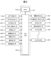
- FIG. 2 shows the input / output relationship of the engine control unit.
- the engine control unit 101 includes an I / O LSI 101a including an A / D converter, a CPU 101b, and the like, and includes an airflow sensor 103, a throttle opening sensor 107, a crank angle sensor 116, a water temperature sensor 202, an air-fuel ratio sensor 203, and a fuel pressure sensor 204.
- a predetermined control signal is supplied to the throttle valve 104, the high pressure pump solenoid 206, the ignition coil 110, and each injector 109, and common rail internal combustion pressure control, fuel injection amount control, ignition timing control, and the like are executed.
- a drive circuit for driving each injector is provided in the I / OLSI, and the voltage supplied from the battery is boosted and supplied using a booster circuit (not shown), and the current is controlled by the IC (not shown). To drive each injector.
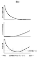
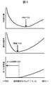
- the horizontal axis of each figure represents the injection timing during the intake stroke of the engine based on the crank signal, TDC means the top dead center of the piston, and BDC means the bottom dead center of the piston.
- TDC means the top dead center of the piston
- BDC means the bottom dead center of the piston.
- the fuel adhesion to the cylinder bore is relatively less affected by the amount of PM generated than the fuel adhesion to the piston crown.
- the sum of the amount of fuel adhering to the piston crown and the amount of fuel adhering to the cylinder bore is minimized in the middle of the intake stroke. It is desirable to inject fuel.
- the fuel injection timing at which the PM emission is minimized is in the middle of the intake stroke, whereas the fuel injection timing at which the fuel consumption rate and oil dilution amount are minimized is at the beginning of the intake stroke. It is desirable to reduce PM in an early fuel injection timing state.
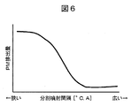
- FIG. 5 is used to explain the relationship between the number of divided injections and the PM emission amount.
- the interval for performing the divided injection is too narrow, the effect of the divided injection cannot be obtained sufficiently and the PM emission amount cannot be reduced.
- the PM emission amount it is indicated that it is necessary to make an interval between injections more than a predetermined interval.
- the end timing of injection is retarded. If the end timing of the divided final injection is on the retard side of the predetermined crank angle, it may not be able to completely evaporate until ignition, and the homogeneity of the mixture in the cylinder tends to decrease. Have.
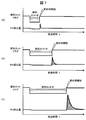
- This figure shows a case where a fuel cut that temporarily stops fuel injection is performed due to operating conditions such as deceleration, idle stop, and motor driving of a hybrid vehicle, and then fuel injection is restarted with split injection at a certain number of times.
- PM emissions are shown.
- the amount of PM emission varies greatly depending on the duration of fuel cut. That is, when the fuel cut duration is short as shown in FIG. 9A, the PM emission amount is small, and as the fuel cut duration is long as shown in FIG. 9C, the PM emission amount tends to increase.
- the fuel cut duration time is short, the fuel is injected in a state where the temperature of the cylinder inner wall surface including the piston crown surface is high, and the adhesion and remaining of the fuel are small due to the promotion of fuel vaporization.
- the fuel cut duration time is long, the fuel is injected in a state where the temperature of the cylinder inner wall surface including the piston crown surface is lowered, the fuel vaporization becomes dull, and the fuel adheres and remains.
- the amount of fuel adhering to the piston crown surface and the cylinder bore is closely related to the piston crown surface temperature and the cylinder bore wall surface temperature, and the fuel adhesion amount increases as the respective temperatures decrease.
- the in-cylinder temperature including the piston crown surface decreases, the amount of fuel adhesion increases when fuel injection is resumed.
- split injection in which fuel injection is performed a plurality of times during one combustion cycle is effective.
- the first injection of the multiple injections is possible so that the amount of fuel adhering to and remaining on the cylinder bore wall surface is reduced. It is necessary to reduce the amount of fuel adhering to and remaining on the piston crown while advancing as much as possible.
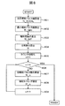
- FIG. 8 is a flowchart showing the control contents of the divided multi-stage injection control according to the embodiment of the present invention.
- the engine control unit 101 supplies a predetermined control signal to each injector 109 based on the injection pulse width and the injection timing calculated in the processing content of FIG. 8, and executes a plurality of fuel injections during one combustion cycle.
- a total injection pulse width TI_TOTAL which is the total amount of fuel injected from each injector 109 during one combustion cycle.
- the total injection pulse width TI_TOTAL is set according to the intake air amount measured by the airflow sensor 103, the air-fuel ratio set according to the operating state, the fuel pressure calculated using the signal of the fuel pressure sensor 204, and the like. .
- the minimum injection pulse width TI_MIN is calculated.
- the minimum injection pulse width is set from various characteristics such as fuel pressure characteristics, electrical characteristics, mechanical characteristics, and injector drive current waveform.
- an injection interval which is an injection interval of each divided injection is calculated.
- the injection interval is set to be equal to or greater than a predetermined interval from the viewpoint of fuel adhesion and the homogeneity of the air-fuel mixture and the aspect of securing the injector drive current.
- the injection interval is too narrow, the fuel spray state is almost the same as that of the single injection, and the effect of the divided injection cannot be obtained and the fuel adhesion to the piston crown surface and the cylinder bore cannot be reduced.
- the voltage in the booster circuit decreases every time the injector is driven, the injector drive circuit needs time to return to the original voltage. During this boost recovery time, it is necessary to wait for the next fuel injection. is there.
- step 804 the division number N is set.
- the division number N is determined by the engine speed and the engine load state parameter.
- step 805 the counter n is initialized.
- step 808 the injection timing of each injection of the divided multi-stage injection is set. Details of step 808 are shown in FIG.
- step 807 injection pulse width of each injection
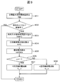
- step 903 a time TMFC during which the fuel cut is continued is calculated.
- a correction coefficient for the split injection ratio during fuel cut recovery is calculated according to the fuel cut duration TMFC.
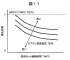
- the correction coefficient KFC is calculated by referring to a map MKFC as shown in FIG. 11 with the fuel cut duration TMFC calculated in step 903 and the piston crown surface temperature TAPI as inputs. Thereby, the division
- the piston crown surface temperature TEPI is preferably estimated by constructing a thermal model using the intake air amount, air-fuel ratio, and ignition timing, but from the viewpoint of simplification of control, the water temperature sensor 202, oil temperature sensor 205, intake temperature sensor The map may be searched using the water temperature, oil temperature, and intake air temperature detected at 118 as input values. In calculating the correction coefficient KFC, either the fuel cut duration TMFC or the piston crown surface temperature TAPI may be input.
- step 905 a correction amount KFCRA for returning to the fuel injection ratio in the normal state after the fuel cut recovery according to the fuel cut duration TMFC is calculated.
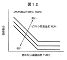
- the recovery correction coefficient is calculated by referring to the map MKFCRA as shown in FIG. 12 with the fuel cut duration TMFC calculated in step 903 and the piston crown surface temperature TAPI as inputs. Thereby, it is possible to return to the normal injection ratio at an appropriate time according to the in-cylinder temperature together with the correction of the divided injection ratio.
- the map MKFCRA is set in consideration of the fuel adhesion amount and vaporization rate due to the piston crown surface temperature TEPI. In calculating the correction amount KFCRA, either the fuel cut duration TMFC or the piston crown surface temperature TEPI may be input.
- the piston crown surface temperature TEPI is preferably estimated by constructing a thermal model using the air amount, air-fuel ratio, and ignition timing, but from the viewpoint of simplification of control, the water temperature sensor 202, the oil temperature sensor 205, and the intake air temperature sensor 118 are used.
- the map may be searched using the detected water temperature, oil temperature, and intake air temperature as input values.
- it is determined whether or not it is the first injection of the divided injections.
- step 907 the process proceeds to step 907 to calculate the first injection amount.
- the first injection amount TI_1 is calculated by the following formula (1) using TIB as an upper limit value.
- TI_1 TIB ⁇ KFC + KFCRA (1)
- the second and subsequent injection amounts TI_n are calculated by the following equation (2).
- TI_n TIB + (TIB-TI_1) / N (2) Details of step 808 (setting injection timing) in FIG. 8 will be described with reference to FIG.
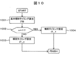
- step 1001 basic injection timing is calculated.
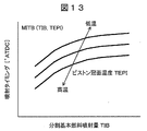
- the basic injection timing ITB is calculated by referring to a map MITB as shown in FIG. 13 by using the divided basic fuel injection amount TIB calculated in step 901 of FIG. 9 and the piston crown surface temperature TEPI as inputs.
- the map MITB is set in consideration of the influence of the fuel adhesion amount and vaporization rate due to the piston crown surface temperature TEPI.
- the crown surface temperature TEPI is preferably estimated by configuring a thermal model using the air amount, air-fuel ratio, ignition timing, etc., but from the viewpoint of simplification of control, the water temperature sensor 202, the oil temperature sensor 205, The map may be searched using the water temperature, oil temperature, and intake air temperature detected by the intake air temperature sensor 118 as input values. Further, the fuel cut duration TMFC may be input instead of the crown surface temperature TEPI or in combination with the crown surface temperature TAPI.
- the post-division injection pulse width TI_ (n ⁇ 1) and the injection interval TI_INT calculated in step 803 in FIG. 8 are added to the previous IT_ (n ⁇ 1) to calculate the nth injection start possible angle IT_n.
- FIGS. 8 to 13 A specific control example when configured as shown in FIGS. 8 to 13 will be described with reference to FIGS.
- FIG. 14 is a diagram showing the injection ratio at the time of split injection when the fuel cut duration is short
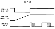
- FIG. 15 is a diagram when the fuel cut duration is long.
- FIG. 15 where the fuel cut duration is long compared to FIG. 14 where the fuel cut duration is short, the first injection ratio is decreased, and the decreased amount is increased by the second injection ratio.
- two injections are shown as an example, but the same applies regardless of the number of injections, and the first decrease is added to the second and subsequent injections.
- the timing among the injections divided into a plurality of times is faster at the timing when the fuel injection is restarted from the fuel cut state. Since the injection amount ratio of the timing injection is set according to the fuel cut duration, the fuel amount adhering to and remaining on the piston crown surface can be reduced while advancing the early injection as much as possible, and the number of PM exhaust particles Can be suppressed.
Landscapes
- Engineering & Computer Science (AREA)
- Chemical & Material Sciences (AREA)
- Combustion & Propulsion (AREA)
- Mechanical Engineering (AREA)
- General Engineering & Computer Science (AREA)
- Electrical Control Of Air Or Fuel Supplied To Internal-Combustion Engine (AREA)
- Combined Controls Of Internal Combustion Engines (AREA)
Abstract
Description
101 エンジン制御ユニット
102 エアクリーナ
103 エアフロセンサ
104 電制スロットル弁
105 吸気管
106 燃焼室
107 スロットル開度センサ
108 高圧燃料ポンプ
109 インジェクタ
110 点火コイル
111 点火プラグ
112 EGR管
113 EGR制御弁
114 EGRガス流量センサ
115 クランク軸
116 クランク角センサ
117 コモンレール
118 吸気温センサ
201 カム角センサ
202 水温センサ
203 空燃比センサ
204 燃圧センサ
205 油温センサ
206 高圧ポンプソレノイド
207 低圧燃料ポンプ
n≠1の場合、ステップ908に進み、2回目以降の噴射量を算出する。
図10を用いて、図8のステップ808(噴射タイミング設定)の詳細について説明する。
Claims (9)
- 1燃焼サイクル中に複数回、燃焼室内へ燃料を分割噴射する筒内噴射式内燃機関の制御装置において、
車両の運転状態に応じて前記燃焼室内への燃料噴射を一時的に停止した後、前記燃焼室内への燃料噴射を再開するときに、
燃料噴射を停止してから再開するまでの燃料カット期間が長い場合は、前記燃料カット期間が短い場合よりも、
前記分割噴射のうち少なくとも初回の噴射量割合を前記分割噴射の残りの噴射量割合と比較して減少させるよう制御することを特徴とする制御装置。 - 1燃焼サイクル中に複数回、燃焼室内へ燃料を分割噴射する筒内噴射式内燃機関の制御装置において、
車両の運転状態に応じて前記燃焼室内への燃料噴射を一時的に停止した後、前記燃焼室内への燃料噴射を再開する時に、
前記燃焼室のピストン冠面の推定温度が低い場合は、前記推定温度が高い場合よりも、
前記分割噴射のうち少なくとも初回の噴射量割合を前記分割噴射の残りの噴射量割合と比較して減少させるよう制御することを特徴とする制御装置。 - 請求項1または2に記載の制御装置において、
減少するよう制御された前記分割噴射のうち少なくとも初回の噴射量割合は、
前記燃料カット期間、または前記推定温度の少なくとも一方に基づいて設定された復帰時間経過後に、燃料噴射を再開する時以外の通常時の燃料噴射量割合へ復帰させることを特徴とする制御装置。 - 請求項3に記載の制御装置において、
前記燃料カット期間が長いほど、または前記推定温度が低いほど、
前記復帰時間を長く設定することを特徴とする制御装置。 - 請求項3に記載の制御装置において、
前記推定温度は、前記筒内噴射式内燃機関の冷却水温度、潤滑油温度、吸入空気温度、前記燃料カット期間中の吸入空気量、空燃比、点火時期のうち少なくとも一つに基づいて推定されることを特徴とする制御装置。 - 請求項3に記載の制御装置において、
燃料噴射を再開する時、
前記燃料カット期間が長いほど、または前記推定温度が低いほど、
前記分割噴射のうち少なくとも初回の噴射タイミングを遅角させることを特徴とする制御装置。 - 請求項3に記載の制御装置において、
少なくとも前記推定温度に基づいて、前記分割噴射のうち少なくとも初回の噴射量割合を前記分割噴射の残りの噴射量割合と比較して減少させるよう制御することを特徴とする制御装置。 - 請求項3に記載の制御装置において、
少なくとも前記燃料カット期間に基づいて、前記復帰時間を設定することを特徴とする制御装置。 - 請求項3に記載の制御装置において、
少なくとも前記推定温度に基づいて、前記復帰時間を設定することを特徴とする制御装置。
Priority Applications (3)
| Application Number | Priority Date | Filing Date | Title |
|---|---|---|---|
| US14/119,349 US9181912B2 (en) | 2011-05-23 | 2012-05-18 | Control device for in-cylinder injection type internal combustion engine |
| DE112012002218.1T DE112012002218B4 (de) | 2011-05-23 | 2012-05-18 | Steuervorrichtung für einen Verbrennungsmotor der Direkteinspritzungsbauart |
| CN201280024919.3A CN103562531B (zh) | 2011-05-23 | 2012-05-18 | 缸内喷射式内燃机的控制装置 |
Applications Claiming Priority (2)
| Application Number | Priority Date | Filing Date | Title |
|---|---|---|---|
| JP2011114277A JP5396430B2 (ja) | 2011-05-23 | 2011-05-23 | 筒内噴射式内燃機関の制御装置 |
| JP2011-114277 | 2011-05-23 |
Publications (1)
| Publication Number | Publication Date |
|---|---|
| WO2012161127A1 true WO2012161127A1 (ja) | 2012-11-29 |
Family
ID=47217204
Family Applications (1)
| Application Number | Title | Priority Date | Filing Date |
|---|---|---|---|
| PCT/JP2012/062834 Ceased WO2012161127A1 (ja) | 2011-05-23 | 2012-05-18 | 筒内噴射式内燃機関の制御装置 |
Country Status (5)
| Country | Link |
|---|---|
| US (1) | US9181912B2 (ja) |
| JP (1) | JP5396430B2 (ja) |
| CN (1) | CN103562531B (ja) |
| DE (1) | DE112012002218B4 (ja) |
| WO (1) | WO2012161127A1 (ja) |
Cited By (2)
| Publication number | Priority date | Publication date | Assignee | Title |
|---|---|---|---|---|
| WO2015043774A1 (de) * | 2013-09-30 | 2015-04-02 | Continental Automotive Gmbh | Verfahren und vorrichtung zur steuerung des übergangs zwischen dem betrieb mit schubabschaltung und normalbetrieb einer mit kraftstoff-direkteinspritzung betriebenen brennkraftmaschine |
| FR3030632A1 (fr) * | 2014-12-22 | 2016-06-24 | Continental Automotive France | Procede d'injection indirecte de carburant pour un moteur a combustion interne, consistant a decouper la quantite de carburant injectee |
Families Citing this family (14)
| Publication number | Priority date | Publication date | Assignee | Title |
|---|---|---|---|---|
| JP5562910B2 (ja) * | 2011-06-30 | 2014-07-30 | 日立オートモティブシステムズ株式会社 | 筒内噴射式エンジンの制御装置 |
| JP6090593B2 (ja) * | 2014-06-24 | 2017-03-08 | トヨタ自動車株式会社 | 内燃機関の燃料噴射システム |
| MX361853B (es) | 2014-11-27 | 2018-12-18 | Nissan Motor | Dispositivo de control y método de control de motor de combustión interna. |
| JP6156593B2 (ja) * | 2014-12-02 | 2017-07-05 | 日産自動車株式会社 | 内燃機関の制御装置 |
| JP6187709B2 (ja) * | 2014-12-02 | 2017-08-30 | 日産自動車株式会社 | 内燃機関の制御装置 |
| EP3232037B1 (en) * | 2014-12-09 | 2019-01-30 | Nissan Motor Co., Ltd | Control device for internal combustion engine |
| KR101684509B1 (ko) * | 2015-02-05 | 2016-12-08 | 현대자동차 주식회사 | 입자상물질 저감을 위한 연료분사 제어방법 |
| JP6120019B2 (ja) * | 2015-02-19 | 2017-04-26 | トヨタ自動車株式会社 | 内燃機関の制御装置 |
| RU2649876C1 (ru) * | 2015-04-14 | 2018-04-05 | Ниссан Мотор Ко., Лтд. | Устройство и способ для регулирования двигателя |
| JP6296045B2 (ja) * | 2015-12-08 | 2018-03-20 | トヨタ自動車株式会社 | 内燃機関の制御装置 |
| WO2019069443A1 (ja) * | 2017-10-06 | 2019-04-11 | 日産自動車株式会社 | 内燃機関の制御方法及び内燃機関の制御装置 |
| US11519352B2 (en) | 2019-08-26 | 2022-12-06 | Kohler Co. | Spark ignited single cylinder engine derate for overheat |
| US11799342B2 (en) | 2020-02-20 | 2023-10-24 | Kohler Co. | Printed circuit board electrical machine |
| JP2021161974A (ja) * | 2020-03-31 | 2021-10-11 | 本田技研工業株式会社 | 燃料噴射制御装置 |
Citations (3)
| Publication number | Priority date | Publication date | Assignee | Title |
|---|---|---|---|---|
| JPH0742585A (ja) * | 1993-08-03 | 1995-02-10 | Daihatsu Motor Co Ltd | 始動時燃料制御方法 |
| JP2003097319A (ja) * | 2001-09-26 | 2003-04-03 | Toyota Motor Corp | 筒内噴射式内燃機関の制御装置 |
| JP2006348908A (ja) * | 2005-06-20 | 2006-12-28 | Fujitsu Ten Ltd | エンジン制御装置、エンジン制御システム及びエンジン制御方法 |
Family Cites Families (17)
| Publication number | Priority date | Publication date | Assignee | Title |
|---|---|---|---|---|
| JP3791032B2 (ja) | 1996-01-09 | 2006-06-28 | 日産自動車株式会社 | 内燃機関の燃料噴射制御装置 |
| US6330796B1 (en) * | 1998-08-03 | 2001-12-18 | Mazda Motor Corporation | Control device for direct injection engine |
| JP3692930B2 (ja) | 2000-11-27 | 2005-09-07 | 日産自動車株式会社 | 直噴火花点火式内燃機関の燃焼制御装置 |
| US6912989B2 (en) * | 2003-04-30 | 2005-07-05 | Nissan Motor Co., Ltd. | Fuel injection control device for a direct fuel injection engine |
| JP2005240755A (ja) * | 2004-02-27 | 2005-09-08 | Nissan Motor Co Ltd | エンジンの燃料噴射制御装置 |
| JP2006291971A (ja) * | 2006-06-28 | 2006-10-26 | Denso Corp | 筒内噴射式内燃機関の燃料噴射制御装置 |
| US7726282B2 (en) * | 2006-08-04 | 2010-06-01 | Toyota Jidosha Kabushiki Kaisha | Direct injection spark ignition internal combustion engine and fuel injection method for same |
| JP4404111B2 (ja) * | 2007-07-19 | 2010-01-27 | トヨタ自動車株式会社 | 内燃機関の燃料噴射制御装置 |
| JP5104195B2 (ja) | 2007-10-19 | 2012-12-19 | トヨタ自動車株式会社 | 火花点火内燃機関 |
| JP2009102998A (ja) | 2007-10-19 | 2009-05-14 | Toyota Motor Corp | 火花点火内燃機関 |
| CN102414426B (zh) * | 2009-04-22 | 2014-04-02 | 丰田自动车株式会社 | 内燃机的控制装置 |
| US7900601B2 (en) * | 2009-05-13 | 2011-03-08 | Gm Global Technology Operations, Inc. | Injection advancement for piston cooling in spark ignition direct injection engines |
| JP5325756B2 (ja) * | 2009-12-14 | 2013-10-23 | 日立オートモティブシステムズ株式会社 | 内燃機関の燃料噴射制御装置 |
| JP5372728B2 (ja) * | 2009-12-25 | 2013-12-18 | 日立オートモティブシステムズ株式会社 | 筒内噴射式内燃機関の制御装置 |
| JP5303511B2 (ja) * | 2010-06-11 | 2013-10-02 | 日立オートモティブシステムズ株式会社 | 筒内燃料噴射式内燃機関の制御装置 |
| US8447496B2 (en) * | 2010-09-17 | 2013-05-21 | Ford Global Technologies, Llc | Fuel-based injection control |
| US8989989B2 (en) * | 2012-09-13 | 2015-03-24 | GM Global Technology Operations LLC | System and method for controlling fuel injection in an engine based on piston temperature |
-
2011
- 2011-05-23 JP JP2011114277A patent/JP5396430B2/ja not_active Expired - Fee Related
-
2012
- 2012-05-18 DE DE112012002218.1T patent/DE112012002218B4/de not_active Expired - Fee Related
- 2012-05-18 WO PCT/JP2012/062834 patent/WO2012161127A1/ja not_active Ceased
- 2012-05-18 CN CN201280024919.3A patent/CN103562531B/zh not_active Expired - Fee Related
- 2012-05-18 US US14/119,349 patent/US9181912B2/en active Active
Patent Citations (3)
| Publication number | Priority date | Publication date | Assignee | Title |
|---|---|---|---|---|
| JPH0742585A (ja) * | 1993-08-03 | 1995-02-10 | Daihatsu Motor Co Ltd | 始動時燃料制御方法 |
| JP2003097319A (ja) * | 2001-09-26 | 2003-04-03 | Toyota Motor Corp | 筒内噴射式内燃機関の制御装置 |
| JP2006348908A (ja) * | 2005-06-20 | 2006-12-28 | Fujitsu Ten Ltd | エンジン制御装置、エンジン制御システム及びエンジン制御方法 |
Cited By (6)
| Publication number | Priority date | Publication date | Assignee | Title |
|---|---|---|---|---|
| WO2015043774A1 (de) * | 2013-09-30 | 2015-04-02 | Continental Automotive Gmbh | Verfahren und vorrichtung zur steuerung des übergangs zwischen dem betrieb mit schubabschaltung und normalbetrieb einer mit kraftstoff-direkteinspritzung betriebenen brennkraftmaschine |
| CN105579692A (zh) * | 2013-09-30 | 2016-05-11 | 大陆汽车有限公司 | 用于对在以直接燃料喷射运转的内燃发动机的超限切断操作与正常操作之间的转换进行控制的方法和装置 |
| KR101815798B1 (ko) | 2013-09-30 | 2018-01-05 | 콘티넨탈 오토모티브 게엠베하 | 직접 연료 분사로 동작하는 내연 엔진의 오버런 차단 동작과 정상 동작 간의 전이를 제어하는 방법 및 디바이스 |
| US9903304B2 (en) | 2013-09-30 | 2018-02-27 | Continental Automotive Gmbh | Control for overrun cutoff of internal combustion engine |
| CN105579692B (zh) * | 2013-09-30 | 2018-09-18 | 大陆汽车有限公司 | 内燃发动机的超限切断操作与正常操作之间的转换控制 |
| FR3030632A1 (fr) * | 2014-12-22 | 2016-06-24 | Continental Automotive France | Procede d'injection indirecte de carburant pour un moteur a combustion interne, consistant a decouper la quantite de carburant injectee |
Also Published As
| Publication number | Publication date |
|---|---|
| US20140182557A1 (en) | 2014-07-03 |
| DE112012002218T5 (de) | 2014-06-12 |
| US9181912B2 (en) | 2015-11-10 |
| CN103562531B (zh) | 2015-10-14 |
| JP2012241654A (ja) | 2012-12-10 |
| CN103562531A (zh) | 2014-02-05 |
| JP5396430B2 (ja) | 2014-01-22 |
| DE112012002218B4 (de) | 2018-10-18 |
Similar Documents
| Publication | Publication Date | Title |
|---|---|---|
| JP5396430B2 (ja) | 筒内噴射式内燃機関の制御装置 | |
| JP5303511B2 (ja) | 筒内燃料噴射式内燃機関の制御装置 | |
| JP5372728B2 (ja) | 筒内噴射式内燃機関の制御装置 | |
| WO2016084188A1 (ja) | 内燃機関の制御装置および制御方法 | |
| JP2011052670A (ja) | 内燃機関の燃料噴射装置 | |
| WO2014057825A1 (ja) | エンジンの制御装置及びエンジンの制御方法 | |
| CN103635679B (zh) | 缸内喷射式发动机的控制装置 | |
| JP5691914B2 (ja) | 排気再循環システムの制御装置 | |
| CN100513774C (zh) | 内燃机的点火时间控制装置 | |
| JP6181012B2 (ja) | 筒内燃料噴射式内燃機関の制御装置 | |
| JP5703341B2 (ja) | 筒内噴射式内燃機関の制御装置 | |
| CN106922160B (zh) | 内燃机的控制装置 | |
| CN107002563A (zh) | 内燃机的控制装置 | |
| CN113464294B (zh) | 燃料喷射控制装置 | |
| JP5488707B2 (ja) | 内燃機関の燃料噴射制御装置 | |
| JP2015151977A (ja) | 筒内燃料噴射式内燃機関の制御装置 | |
| JP2014074337A (ja) | 内燃機関の制御装置 | |
| JP2006132400A (ja) | 内燃機関の燃料噴射制御方法 | |
| JP2004197724A (ja) | 直噴エンジンの燃料噴射制御装置 | |
| JP2010048116A (ja) | 筒内噴射式の内燃機関の燃料噴射制御装置 | |
| JP2011038408A (ja) | 燃費改善方法及び噴射制御装置 |
Legal Events
| Date | Code | Title | Description |
|---|---|---|---|
| 121 | Ep: the epo has been informed by wipo that ep was designated in this application |
Ref document number: 12788812 Country of ref document: EP Kind code of ref document: A1 |
|
| WWE | Wipo information: entry into national phase |
Ref document number: 14119349 Country of ref document: US |
|
| WWE | Wipo information: entry into national phase |
Ref document number: 112012002218 Country of ref document: DE Ref document number: 1120120022181 Country of ref document: DE |
|
| 122 | Ep: pct application non-entry in european phase |
Ref document number: 12788812 Country of ref document: EP Kind code of ref document: A1 |