WO2012160917A1 - ロードポート装置、搬送システム、及びコンテナ搬出方法 - Google Patents
ロードポート装置、搬送システム、及びコンテナ搬出方法 Download PDFInfo
- Publication number
- WO2012160917A1 WO2012160917A1 PCT/JP2012/060730 JP2012060730W WO2012160917A1 WO 2012160917 A1 WO2012160917 A1 WO 2012160917A1 JP 2012060730 W JP2012060730 W JP 2012060730W WO 2012160917 A1 WO2012160917 A1 WO 2012160917A1
- Authority
- WO
- WIPO (PCT)
- Prior art keywords
- container
- nozzle
- port
- gas
- gas port
- Prior art date
Links
Images


Classifications
-
- H—ELECTRICITY
- H01—ELECTRIC ELEMENTS
- H01L—SEMICONDUCTOR DEVICES NOT COVERED BY CLASS H10
- H01L21/00—Processes or apparatus adapted for the manufacture or treatment of semiconductor or solid state devices or of parts thereof
- H01L21/67—Apparatus specially adapted for handling semiconductor or electric solid state devices during manufacture or treatment thereof; Apparatus specially adapted for handling wafers during manufacture or treatment of semiconductor or electric solid state devices or components ; Apparatus not specifically provided for elsewhere
- H01L21/677—Apparatus specially adapted for handling semiconductor or electric solid state devices during manufacture or treatment thereof; Apparatus specially adapted for handling wafers during manufacture or treatment of semiconductor or electric solid state devices or components ; Apparatus not specifically provided for elsewhere for conveying, e.g. between different workstations
-
- B—PERFORMING OPERATIONS; TRANSPORTING
- B65—CONVEYING; PACKING; STORING; HANDLING THIN OR FILAMENTARY MATERIAL
- B65B—MACHINES, APPARATUS OR DEVICES FOR, OR METHODS OF, PACKAGING ARTICLES OR MATERIALS; UNPACKING
- B65B31/00—Packaging articles or materials under special atmospheric or gaseous conditions; Adding propellants to aerosol containers
- B65B31/04—Evacuating, pressurising or gasifying filled containers or wrappers by means of nozzles through which air or other gas, e.g. an inert gas, is withdrawn or supplied
-
- H—ELECTRICITY
- H01—ELECTRIC ELEMENTS
- H01L—SEMICONDUCTOR DEVICES NOT COVERED BY CLASS H10
- H01L21/00—Processes or apparatus adapted for the manufacture or treatment of semiconductor or solid state devices or of parts thereof
- H01L21/67—Apparatus specially adapted for handling semiconductor or electric solid state devices during manufacture or treatment thereof; Apparatus specially adapted for handling wafers during manufacture or treatment of semiconductor or electric solid state devices or components ; Apparatus not specifically provided for elsewhere
- H01L21/673—Apparatus specially adapted for handling semiconductor or electric solid state devices during manufacture or treatment thereof; Apparatus specially adapted for handling wafers during manufacture or treatment of semiconductor or electric solid state devices or components ; Apparatus not specifically provided for elsewhere using specially adapted carriers or holders; Fixing the workpieces on such carriers or holders
- H01L21/6735—Closed carriers
- H01L21/67389—Closed carriers characterised by atmosphere control
- H01L21/67393—Closed carriers characterised by atmosphere control characterised by the presence of atmosphere modifying elements inside or attached to the closed carrierl
-
- B—PERFORMING OPERATIONS; TRANSPORTING
- B65—CONVEYING; PACKING; STORING; HANDLING THIN OR FILAMENTARY MATERIAL
- B65G—TRANSPORT OR STORAGE DEVICES, e.g. CONVEYORS FOR LOADING OR TIPPING, SHOP CONVEYOR SYSTEMS OR PNEUMATIC TUBE CONVEYORS
- B65G1/00—Storing articles, individually or in orderly arrangement, in warehouses or magazines
- B65G1/02—Storage devices
- B65G1/04—Storage devices mechanical
-
- H—ELECTRICITY
- H01—ELECTRIC ELEMENTS
- H01L—SEMICONDUCTOR DEVICES NOT COVERED BY CLASS H10
- H01L21/00—Processes or apparatus adapted for the manufacture or treatment of semiconductor or solid state devices or of parts thereof
- H01L21/67—Apparatus specially adapted for handling semiconductor or electric solid state devices during manufacture or treatment thereof; Apparatus specially adapted for handling wafers during manufacture or treatment of semiconductor or electric solid state devices or components ; Apparatus not specifically provided for elsewhere
- H01L21/677—Apparatus specially adapted for handling semiconductor or electric solid state devices during manufacture or treatment thereof; Apparatus specially adapted for handling wafers during manufacture or treatment of semiconductor or electric solid state devices or components ; Apparatus not specifically provided for elsewhere for conveying, e.g. between different workstations
- H01L21/67703—Apparatus specially adapted for handling semiconductor or electric solid state devices during manufacture or treatment thereof; Apparatus specially adapted for handling wafers during manufacture or treatment of semiconductor or electric solid state devices or components ; Apparatus not specifically provided for elsewhere for conveying, e.g. between different workstations between different workstations
- H01L21/67733—Overhead conveying
-
- H—ELECTRICITY
- H01—ELECTRIC ELEMENTS
- H01L—SEMICONDUCTOR DEVICES NOT COVERED BY CLASS H10
- H01L21/00—Processes or apparatus adapted for the manufacture or treatment of semiconductor or solid state devices or of parts thereof
- H01L21/67—Apparatus specially adapted for handling semiconductor or electric solid state devices during manufacture or treatment thereof; Apparatus specially adapted for handling wafers during manufacture or treatment of semiconductor or electric solid state devices or components ; Apparatus not specifically provided for elsewhere
- H01L21/677—Apparatus specially adapted for handling semiconductor or electric solid state devices during manufacture or treatment thereof; Apparatus specially adapted for handling wafers during manufacture or treatment of semiconductor or electric solid state devices or components ; Apparatus not specifically provided for elsewhere for conveying, e.g. between different workstations
- H01L21/67703—Apparatus specially adapted for handling semiconductor or electric solid state devices during manufacture or treatment thereof; Apparatus specially adapted for handling wafers during manufacture or treatment of semiconductor or electric solid state devices or components ; Apparatus not specifically provided for elsewhere for conveying, e.g. between different workstations between different workstations
- H01L21/67736—Loading to or unloading from a conveyor
-
- H—ELECTRICITY
- H01—ELECTRIC ELEMENTS
- H01L—SEMICONDUCTOR DEVICES NOT COVERED BY CLASS H10
- H01L21/00—Processes or apparatus adapted for the manufacture or treatment of semiconductor or solid state devices or of parts thereof
- H01L21/67—Apparatus specially adapted for handling semiconductor or electric solid state devices during manufacture or treatment thereof; Apparatus specially adapted for handling wafers during manufacture or treatment of semiconductor or electric solid state devices or components ; Apparatus not specifically provided for elsewhere
- H01L21/677—Apparatus specially adapted for handling semiconductor or electric solid state devices during manufacture or treatment thereof; Apparatus specially adapted for handling wafers during manufacture or treatment of semiconductor or electric solid state devices or components ; Apparatus not specifically provided for elsewhere for conveying, e.g. between different workstations
- H01L21/67763—Apparatus specially adapted for handling semiconductor or electric solid state devices during manufacture or treatment thereof; Apparatus specially adapted for handling wafers during manufacture or treatment of semiconductor or electric solid state devices or components ; Apparatus not specifically provided for elsewhere for conveying, e.g. between different workstations the wafers being stored in a carrier, involving loading and unloading
- H01L21/67769—Storage means
Definitions
- the present invention relates to a load port device for unloading a container having an internal space and a gas port from a processing device, a transport system using the load port device, and a container unloading method.
- the load port device is a device that enters or leaves a sealed container in which a substrate is stored from a semiconductor processing device or an automatic warehouse, for example.
- the sealed container is transported from the load port device to another device by a transport vehicle (see, for example, Patent Document 1).
- the sealed container is, for example, FOUP or SMIF.
- the hermetic container is in a hermetically sealed state, which prevents dust from entering the inside. Further, the atmosphere inside the sealed container is replaced with an inert gas such as nitrogen gas, thereby preventing growth of an oxide film due to natural oxidation of the semiconductor substrate.
- the portable sealed container has an air supply port and an exhaust port that allow communication between the inside and the outside.
- the gas supply device includes an air supply nozzle that is airtightly connected to the air supply port, and an exhaust nozzle that is airtightly connected to the exhaust port.
- the air supply nozzle is connected to a gas supply source that supplies a purge gas via an air supply pipe.
- the gas exhaust nozzle is connected to a processing apparatus that performs exhaust.
- the purge gas is supplied from the gas supply source into the portable sealed container through the supply pipe, the supply nozzle, and the supply port. Further, when the inside of the sealed container is filled with the purge gas and the inside of the sealed container reaches a predetermined pressure or higher, the purge gas is exhausted through the exhaust port, the exhaust nozzle, and the exhaust pipe.
- the sealed container In the load port device provided in the stocker, the sealed container is transported from the inside of the stocker to the standby position by the transport conveyor.
- the sealed container is in a standby position until it is loaded onto the transport vehicle.
- the concentration of nitrogen gas in the sealed container also decreases during the time until the transport vehicle arrives.
- the nozzle when the container is transported to the loading position by the transport conveyor, the nozzle is then connected to the gas port by the moving mechanism, and in this state, the nozzle mechanism supplies purge gas to the container.
- the controller recognizes that the transport vehicle has arrived at the loading position, the supply of purge gas from the nozzle mechanism to the container is stopped.
- the purge gas is supplied to the container without wasting the waiting time, and the loading by the transport vehicle is also performed quickly as usual. Further, it is possible to prevent the purge gas concentration in the container from decreasing during the waiting time until the container is loaded on the transport vehicle.
- arrival of the transport vehicle at the loading position includes that the transport vehicle is sufficiently close to the loading location and is stopped at the loading position or just before stopping.
- the load port device may further include a determination unit and an alignment mechanism.
- the alignment mechanism aligns the nozzle with the position of the gas port based on the determination result.
- the position of the gas port may be determined by detection by a sensor or by obtaining information on the type of container.
- the alignment mechanism may have a horizontal movement mechanism, and the horizontal movement mechanism may horizontally move the nozzle according to the position of the gas port.
- a transport system includes the load port device described above and a transport vehicle that can load a container from a loading position.
- a container carrying-out method is a device for carrying a container having a gas port to a loading position where loading by a transport vehicle is performed, and uses a load port device.
- the load port device has a transfer conveyor and a nozzle mechanism.
- the transport conveyor extends to the loading position.
- the nozzle mechanism has a nozzle for supplying purge gas into the container by being arranged in the vicinity of the loading position and connected to the gas port, and a moving mechanism for moving the nozzle closer to and away from the gas port.
- the container carrying-out method includes the following steps. ⁇ Transport the container to the loading position by the transport conveyor. ⁇ Connect the nozzle to the gas port of the container at the loading position, and then supply the purge gas into the container.
- FIG. 1 Side surface sectional drawing of a stocker apparatus.
- the perspective view which shows the structure of the port of a stocker apparatus.
- the schematic diagram of a purge apparatus The block diagram which shows the control structure of a stocker apparatus.
- the flowchart which shows the control operation of a stocker apparatus.
- the schematic diagram of a purge apparatus The block diagram which shows the control structure of a stocker apparatus.
- the flowchart which shows the control operation of a stocker apparatus.
- the stocker apparatus 1 is an apparatus that is disposed in a clean room and temporarily stores a container (FOUP in this embodiment).
- FIG. 1 is a side sectional view of the stocker device.
- the stocker apparatus 1 is disposed inside a building 3 that forms a clean room.
- the building 3 has a first floor foundation 5, a first floor 7, a second floor 9, and a building ceiling 11.
- the stocker device 1 includes a main body portion 21, a rack 23, and a stacker crane 25.
- the stocker apparatus 1 further includes a first floor port 41 and a second floor port 43 (described later).
- the main body 21 extends from the first floor foundation 5 through the first floor 7 and further through the second floor 9 and extends to the building ceiling 11.
- the main body 21 is a box having a sealed structure that is shut off from the outside.
- the rack 23 is composed of two rows of left and right racks 23a and 23b arranged opposite to each other.
- the left and right racks 23a and 23b have a plurality of shelves 23A.
- a container 27 is placed on the shelf 23A as illustrated.
- a stacker crane 25 is movably disposed in a central space between the left and right racks 23a and 23b.
- the stacker crane 25 includes a stacker column 31, wheels 33, a travel mechanism (not shown) that drives the wheels 33, and a stacker robot 35 that can move the stacker column 31 up and down.
- the stacker robot 35 is a hand device that scoops and holds the container 27 from below.
- the stacker crane 25 can transfer the container 27 between a predetermined shelf 23 ⁇ / b> A and an inner conveyor unit 51 (described later) of the first floor port 41 and the second floor port 43.
- FIG. 2 is a perspective view showing the structure of the port of the stocker device.
- the first floor port 41 is provided on the first floor side
- the second floor port 43 is provided on the second floor side.
- the container 27 can be loaded and unloaded via these ports 41 and 43.
- the first-floor port 41 and the second-floor port 43 include an opening 45 that opens to the outer surface of the main body 21, and a transport conveyor 47 that is provided on both the inside and outside of the opening 45.
- the transport conveyor 47 includes an outer conveyor unit 49 installed outside the main body 21 and an inner conveyor unit 51 installed inside the main body 21.
- Each outer conveyor unit 49 of the first floor port 41 and the second floor port 43 is supported by a suspension member 55 from the ceiling.
- a ceiling transport vehicle 59 that can run along the rail 57 is provided on the ceiling above the outer conveyor unit 49.
- the overhead conveyance vehicle 59 can carry the container 27 from the outer conveyor unit 49, and can carry the container 27 to the outer conveyor unit 49.
- the overhead conveyance vehicle 59 is controlled by the conveyance vehicle controller 113 (described later).
- the conveyor units 49 and 51 are configured by attaching a driving roller 61 and a driven roller 63 to the left and right side surfaces of a square frame.
- the driving roller 61 is driven by a roller driving mechanism 103 (FIG. 5).
- the outer conveyor unit 49 is provided with a mounting sensor 107 (FIG. 5) for detecting that the container 27 is mounted.
- the outer conveyor unit 49 may or may not be provided with a positioning pin for the container 27.
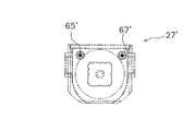
- FIG. 3 is a plan view of the container.
- the container 27 is a container for storing the substrate in a sealed state, and is transported by another device.
- the container 27 has a housing and a lid.
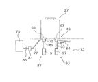
- the purge device 73 has an air supply tank 75, an air supply pipe 77, and an air supply nozzle 79.
- the air supply tank 75 has, for example, clean dry air inside.
- the air supply pipe 77 extends from the air supply tank 75.
- the supply nozzle 79 is fixed to the tip of the supply pipe 77. Further, a flow rate adjusting valve 81 and an opening / closing valve 83 are provided in the middle of the air supply pipe 77.
- the purge device 73 has a first elevating mechanism 87 for elevating the air supply nozzle 79.
- the first elevating mechanism 87 is an air cylinder mechanism, and includes a rod 89 and a cylinder driving unit 91 that drives the rod 89.
- the supply nozzle 79 is movable between a position connected to the supply port 65 and a position disconnected from the supply port 65.
- the purge device 73 has a second elevating mechanism 93 for elevating the exhaust nozzle 85.
- the second elevating mechanism 93 is a cylinder mechanism, and includes a rod 95 and a cylinder driving unit 97 that drives the rod 95.
- the exhaust nozzle 85 is movable between a position connected to the exhaust port 67 and a position disconnected from the exhaust port 67.
- FIG. 5 is a block diagram showing a control configuration of the stocker apparatus 1.
- the stocker controller 101 is a computer, and includes hardware such as a CPU, a RAM, and a ROM, and performs various control operations by executing program instructions.
- the stocker controller 101 is connected to the stacker crane 25, the roller driving mechanism 103, the flow rate adjusting valve 81, the opening / closing valve 83, the first elevating mechanism 87, and the second elevating mechanism 93, and can transmit control signals thereto.
- the stocker controller 101 is connected to the on-board sensor 107 and the ID reader 109, and can receive detection signals from these.
- the stocker controller 101 is connected to the logistics controller 111 so as to be able to communicate.
- the distribution controller 111 is a higher-level controller than the stocker controller 101 and the transport vehicle controller 113.
- the distribution controller 111 receives a conveyance request from a manufacturing controller (not shown)
- the distribution controller 111 transmits an output command to the stocker controller 101 at a predetermined timing when it is accompanied by the output from the stocker device 1.
- the physical distribution controller 111 converts the received transport request into a transport command and assigns it to the ceiling transport vehicle 59.
- the logistics controller 111 transmits a delivery command to the stocker controller 101
- the stocker controller 101 performs a delivery operation by controlling the stacker crane 25 and the roller drive mechanism 103.
- the distribution controller 111 transmits a conveyance command to the conveyance vehicle controller 113.
- the transport vehicle controller 113 assigns a transport command to the ceiling transport vehicle 59.
- FIG. 6 is a flowchart showing the control operation of the stocker apparatus.
- step S1 the stocker controller 101 waits for a delivery command to be transmitted from the logistics controller 111.
- step S2 the stocker controller 101 drives the stacker crane 25 to move the container 27 to the transport conveyor 47.
- the stacker crane 25 carries out the container 27 from the specific shelf 23 ⁇ / b> A and further places the container 27 on the inner conveyor unit 51 of the ports 41 and 43.
- step S ⁇ b> 3 the stocker controller 101 drives the roller drive mechanism 103 to carry out the container 27 from the main body 21 by the transport conveyor 47. Specifically, the conveyor units 49 and 51 are driven in the carry-out direction, and the container 27 moves onto the outer conveyor unit 49.
- step S4 the stocker controller 101 waits for the container 27 to be positioned on the outer conveyor unit 49. Note that whether or not the container 27 is disposed on the outer conveyor unit 49 is determined based on a detection signal from the mounting sensor 107.
- step S6 the stocker controller 101 opens the opening / closing valve 83. Thereby, clean dry air is supplied from the air supply tank 75 into the container 27.
- step S7 the stocker controller 101 waits for a signal from the transport vehicle controller 113 notifying that the ceiling transport vehicle 59 has arrived at the outer conveyor unit 49.
- step S8 the stocker controller 101 closes the open / close valve 83. As a result, the supply of clean dry air from the air supply tank 75 into the container 27 is stopped. This operation is executed even if only a shorter time than the normal purge time has elapsed.
- step S ⁇ b> 9 the stocker controller 101 drives the first elevating mechanism 87 and the second elevating mechanism 93 to lower the air supply nozzle 79 and the exhaust nozzle 85 and disconnect it from the air supply port 65 and the exhaust port 67. In this way, the supply of purge gas is stopped as soon as the ceiling transport vehicle 59 arrives, and the container 27 can be unloaded, so that it does not take extra time for the ceiling transport vehicle 59 to unload the container 27. Thereafter, the container 27 is transported to the processing apparatus of the next process by the ceiling transport vehicle 59.
- the air supply nozzle 79 and the exhaust nozzle 85 are then connected to the air supply port 65 and the exhaust by the first lift mechanism 87 and the second lift mechanism 93.
- the purge device 73 is connected to each of the ports 67, and in this state, purge gas is supplied to the container.
- the stocker controller 101 recognizes that the overhead conveyance vehicle 59 has arrived at the outer conveyor unit 49, the supply of the purge gas from the purge device 73 to the container 27 is stopped.
- the purge gas is supplied to the container 27 without wasting the waiting time, and the loading by the ceiling transport vehicle 59 is also performed quickly as usual.
- FIGS. 7 and 8 are plan views of the container, and FIG. 9 is a schematic view of the purge device.
- FIG. 10 is a block diagram illustrating a control configuration of the stocker apparatus.
- FIG. 11 is a flowchart showing the control operation of the stocker apparatus.
- the positions of the air supply port 65 ′ and the exhaust port 67 ′ are deviated from the positions of the air supply port 65 and the exhaust port 67 of the container 27 shown in the above embodiment. Further, in the container 27 ′′ shown in FIG. 8, the positions of the air supply port 65 ′′ and the exhaust port 67 ′′ are replaced with the positions of the air supply port 65 and the exhaust port 67 of the container 27 shown in the embodiment. Yes.
- the present embodiment adopts the following structure.
- the stocker controller 101 compares the position of the container 27 disposed on the outer conveyor unit 49 for transport with the traveling position of the ceiling transport vehicle 59 with a predetermined threshold value.
- the stocker controller 101 stops the supply of purge gas and disconnects the nozzle and the port when the position of the container 27 and the traveling position become equal to or less than a predetermined threshold value.
- the ceiling transport vehicle 59 arrives at the standby position of the container 27, the container 27 is ready to be transported immediately. That is, the ceiling transport vehicle 59 does not have to wait for the purge gas supply stop, the separation between the nozzles and the ports, and the like, and can transport the container 27 immediately.
Priority Applications (6)
| Application Number | Priority Date | Filing Date | Title |
|---|---|---|---|
| SG2013073002A SG194439A1 (en) | 2011-05-25 | 2012-04-20 | Load port apparatus, carrier system, and container conveyance method |
| US14/118,897 US9701431B2 (en) | 2011-05-25 | 2012-04-20 | Load port device, transport system, and container carrying out method |
| JP2013516254A JP5700119B2 (ja) | 2011-05-25 | 2012-04-20 | ロードポート装置、搬送システム、及びコンテナ搬出方法 |
| CN201280024471.5A CN103548130B (zh) | 2011-05-25 | 2012-04-20 | 载入机装置、搬运系统、以及容器搬出方法 |
| KR1020137032925A KR101495629B1 (ko) | 2011-05-25 | 2012-04-20 | 로드 포트 장치, 반송 시스템 및 컨테이너 반출 방법 |
| EP12789538.1A EP2717306B1 (en) | 2011-05-25 | 2012-04-20 | Load port apparatus, carrier system, and container conveyance method |
Applications Claiming Priority (2)
| Application Number | Priority Date | Filing Date | Title |
|---|---|---|---|
| JP2011116838 | 2011-05-25 | ||
| JP2011-116838 | 2011-05-25 |
Publications (1)
| Publication Number | Publication Date |
|---|---|
| WO2012160917A1 true WO2012160917A1 (ja) | 2012-11-29 |
Family
ID=47217001
Family Applications (1)
| Application Number | Title | Priority Date | Filing Date |
|---|---|---|---|
| PCT/JP2012/060730 WO2012160917A1 (ja) | 2011-05-25 | 2012-04-20 | ロードポート装置、搬送システム、及びコンテナ搬出方法 |
Country Status (8)
| Country | Link |
|---|---|
| US (1) | US9701431B2 (ko) |
| EP (1) | EP2717306B1 (ko) |
| JP (1) | JP5700119B2 (ko) |
| KR (1) | KR101495629B1 (ko) |
| CN (1) | CN103548130B (ko) |
| SG (1) | SG194439A1 (ko) |
| TW (1) | TWI505391B (ko) |
| WO (1) | WO2012160917A1 (ko) |
Cited By (7)
| Publication number | Priority date | Publication date | Assignee | Title |
|---|---|---|---|---|
| WO2016047260A1 (ja) * | 2014-09-25 | 2016-03-31 | 村田機械株式会社 | パージ装置及びパージ方法 |
| JP2016096192A (ja) * | 2014-11-12 | 2016-05-26 | 株式会社ダイフク | 物品搬送設備 |
| JP2016178239A (ja) * | 2015-03-20 | 2016-10-06 | Tdk株式会社 | ガスパージ装置、ロードポート装置およびガスパージ方法 |
| JPWO2015194255A1 (ja) * | 2014-06-16 | 2017-04-20 | 村田機械株式会社 | パージ装置、パージシステム、パージ方法及びパージシステムにおける制御方法 |
| TWI588073B (zh) * | 2015-03-16 | 2017-06-21 | 大福股份有限公司 | 在天花板上存儲和處理物品的裝置 |
| JP2018065655A (ja) * | 2016-10-19 | 2018-04-26 | 株式会社ダイフク | 物品搬送設備 |
| JP2020115591A (ja) * | 2020-04-30 | 2020-07-30 | Tdk株式会社 | フープロードポート装置 |
Families Citing this family (12)
| Publication number | Priority date | Publication date | Assignee | Title |
|---|---|---|---|---|
| CN103922097A (zh) * | 2014-04-08 | 2014-07-16 | 上海华力微电子有限公司 | 搬运系统 |
| KR101608831B1 (ko) | 2014-06-13 | 2016-04-05 | 우범제 | 배출가속기 및 이를 구비한 로드 포트 |
| JP6358143B2 (ja) * | 2015-03-26 | 2018-07-18 | 株式会社ダイフク | 半導体容器保管設備 |
| JP6554872B2 (ja) * | 2015-03-31 | 2019-08-07 | Tdk株式会社 | ガスパージ装置、ロードポート装置、パージ対象容器の設置台およびガスパージ方法 |
| KR20180032624A (ko) * | 2015-08-28 | 2018-03-30 | 무라다기카이가부시끼가이샤 | 보관 장치 및 보관 방법 |
| JP6561700B2 (ja) * | 2015-09-04 | 2019-08-21 | シンフォニアテクノロジー株式会社 | ガス注入装置 |
| JP6455404B2 (ja) * | 2015-11-17 | 2019-01-23 | 株式会社ダイフク | 容器搬送設備 |
| US11608193B2 (en) * | 2017-07-21 | 2023-03-21 | Sentien Robotics, Inc. | UAV retrieval and deployment system |
| US11807458B2 (en) * | 2018-05-23 | 2023-11-07 | Daifuku Co., Ltd. | Picking system |
| SG11202106551XA (en) * | 2018-12-26 | 2021-07-29 | Murata Machinery Ltd | Storage system |
| JP7188615B2 (ja) * | 2019-11-05 | 2022-12-13 | 村田機械株式会社 | 搬送車システム |
| JP7422577B2 (ja) * | 2020-03-23 | 2024-01-26 | 平田機工株式会社 | ロードポート及び制御方法 |
Citations (8)
| Publication number | Priority date | Publication date | Assignee | Title |
|---|---|---|---|---|
| JPH06104328A (ja) * | 1992-08-04 | 1994-04-15 | Internatl Business Mach Corp <Ibm> | 全自動且つコンピュータ化コンベヤベースの製造ライン |
| JP2003060007A (ja) * | 2001-08-20 | 2003-02-28 | Semiconductor Leading Edge Technologies Inc | 基板の移送方法及びロードポート装置並びに基板移送システム |
| JP2004238191A (ja) * | 2003-02-10 | 2004-08-26 | Murata Mach Ltd | 天井走行車システム |
| WO2005101484A1 (ja) * | 2004-04-07 | 2005-10-27 | Right Mfg Co. Ltd. | 基板収納容器の雰囲気置換ポート接続装置 |
| JP2006228808A (ja) * | 2005-02-15 | 2006-08-31 | Seiko Epson Corp | 基板搬送装置、基板搬送方法及び半導体製造装置 |
| JP2008105687A (ja) * | 2006-10-24 | 2008-05-08 | Shin Etsu Handotai Co Ltd | 基板出荷ボックスの識別システム |
| JP2008159734A (ja) * | 2006-12-22 | 2008-07-10 | Asyst Technologies Japan Inc | コンテナの搬送システム及び測定用コンテナ |
| JP2010064806A (ja) | 2008-09-08 | 2010-03-25 | Murata Machinery Ltd | 搬送車システム |
Family Cites Families (19)
| Publication number | Priority date | Publication date | Assignee | Title |
|---|---|---|---|---|
| US5988233A (en) * | 1998-03-27 | 1999-11-23 | Asyst Technologies, Inc. | Evacuation-driven SMIF pod purge system |
| JP3218015B2 (ja) * | 1998-09-01 | 2001-10-15 | セイコーインスツルメンツ株式会社 | 半導体ウェハー観察装置 |
| US6726429B2 (en) * | 2002-02-19 | 2004-04-27 | Vertical Solutions, Inc. | Local store for a wafer processing station |
| US6881020B2 (en) * | 2002-04-26 | 2005-04-19 | Taiwan Semiconductor Manufacturing Co., Ltd | Pod transfer system having retractable mast and rotatable and vertically movable hoist |
| TWI246501B (en) | 2003-02-03 | 2006-01-01 | Murata Machinery Ltd | Overhead traveling carriage system |
| JP3902583B2 (ja) * | 2003-09-25 | 2007-04-11 | Tdk株式会社 | 可搬式密閉容器内部のパージシステムおよびパージ方法 |
| US20090169342A1 (en) * | 2004-06-21 | 2009-07-02 | Takehiko Yoshimura | Load port |
| JP4271095B2 (ja) * | 2004-07-15 | 2009-06-03 | 東京エレクトロン株式会社 | 基板加熱装置及び基板加熱方法 |
| US20110303125A1 (en) * | 2004-11-09 | 2011-12-15 | Hiroshi Itou | Load port and adaptor |
| JP3983254B2 (ja) * | 2005-06-24 | 2007-09-26 | Tdk株式会社 | 製品収容容器用パージシステム及び該パージシステムに供せられる台 |
| JP4527670B2 (ja) * | 2006-01-25 | 2010-08-18 | 東京エレクトロン株式会社 | 加熱処理装置、加熱処理方法、制御プログラムおよびコンピュータ読取可能な記憶媒体 |
| JP5003292B2 (ja) * | 2006-11-07 | 2012-08-15 | シンフォニアテクノロジー株式会社 | 搬送システム |
| JP4859229B2 (ja) * | 2006-12-08 | 2012-01-25 | 東京エレクトロン株式会社 | 熱処理装置 |
| US8492283B2 (en) * | 2007-08-28 | 2013-07-23 | Taiwan Semiconductor Manufacturing Co., Ltd. | Method and structure for automated inert gas charging in a reticle stocker |
| TW200929357A (en) * | 2007-12-20 | 2009-07-01 | Gudeng Prec Industral Co Ltd | Gas filling apparatus |
| JP4692584B2 (ja) * | 2008-07-03 | 2011-06-01 | 村田機械株式会社 | パージ装置 |
| JP5381054B2 (ja) * | 2008-12-02 | 2014-01-08 | シンフォニアテクノロジー株式会社 | ロードポート |
| US8287648B2 (en) * | 2009-02-09 | 2012-10-16 | Asm America, Inc. | Method and apparatus for minimizing contamination in semiconductor processing chamber |
| JP2011187539A (ja) * | 2010-03-05 | 2011-09-22 | Sinfonia Technology Co Ltd | ガス注入装置、ガス排出装置、ガス注入方法及びガス排出方法 |
-
2012
- 2012-04-20 US US14/118,897 patent/US9701431B2/en active Active
- 2012-04-20 WO PCT/JP2012/060730 patent/WO2012160917A1/ja active Application Filing
- 2012-04-20 CN CN201280024471.5A patent/CN103548130B/zh active Active
- 2012-04-20 JP JP2013516254A patent/JP5700119B2/ja active Active
- 2012-04-20 EP EP12789538.1A patent/EP2717306B1/en active Active
- 2012-04-20 KR KR1020137032925A patent/KR101495629B1/ko active IP Right Grant
- 2012-04-20 SG SG2013073002A patent/SG194439A1/en unknown
- 2012-05-25 TW TW101118663A patent/TWI505391B/zh active
Patent Citations (8)
| Publication number | Priority date | Publication date | Assignee | Title |
|---|---|---|---|---|
| JPH06104328A (ja) * | 1992-08-04 | 1994-04-15 | Internatl Business Mach Corp <Ibm> | 全自動且つコンピュータ化コンベヤベースの製造ライン |
| JP2003060007A (ja) * | 2001-08-20 | 2003-02-28 | Semiconductor Leading Edge Technologies Inc | 基板の移送方法及びロードポート装置並びに基板移送システム |
| JP2004238191A (ja) * | 2003-02-10 | 2004-08-26 | Murata Mach Ltd | 天井走行車システム |
| WO2005101484A1 (ja) * | 2004-04-07 | 2005-10-27 | Right Mfg Co. Ltd. | 基板収納容器の雰囲気置換ポート接続装置 |
| JP2006228808A (ja) * | 2005-02-15 | 2006-08-31 | Seiko Epson Corp | 基板搬送装置、基板搬送方法及び半導体製造装置 |
| JP2008105687A (ja) * | 2006-10-24 | 2008-05-08 | Shin Etsu Handotai Co Ltd | 基板出荷ボックスの識別システム |
| JP2008159734A (ja) * | 2006-12-22 | 2008-07-10 | Asyst Technologies Japan Inc | コンテナの搬送システム及び測定用コンテナ |
| JP2010064806A (ja) | 2008-09-08 | 2010-03-25 | Murata Machinery Ltd | 搬送車システム |
Cited By (10)
| Publication number | Priority date | Publication date | Assignee | Title |
|---|---|---|---|---|
| JPWO2015194255A1 (ja) * | 2014-06-16 | 2017-04-20 | 村田機械株式会社 | パージ装置、パージシステム、パージ方法及びパージシステムにおける制御方法 |
| WO2016047260A1 (ja) * | 2014-09-25 | 2016-03-31 | 村田機械株式会社 | パージ装置及びパージ方法 |
| JPWO2016047260A1 (ja) * | 2014-09-25 | 2017-06-15 | 村田機械株式会社 | パージ装置及びパージ方法 |
| TWI667437B (zh) * | 2014-09-25 | 2019-08-01 | 日商村田機械股份有限公司 | Purification device and purification method |
| JP2016096192A (ja) * | 2014-11-12 | 2016-05-26 | 株式会社ダイフク | 物品搬送設備 |
| TWI588073B (zh) * | 2015-03-16 | 2017-06-21 | 大福股份有限公司 | 在天花板上存儲和處理物品的裝置 |
| JP2016178239A (ja) * | 2015-03-20 | 2016-10-06 | Tdk株式会社 | ガスパージ装置、ロードポート装置およびガスパージ方法 |
| JP2018065655A (ja) * | 2016-10-19 | 2018-04-26 | 株式会社ダイフク | 物品搬送設備 |
| US10625938B2 (en) | 2016-10-19 | 2020-04-21 | Daifuku Co., Ltd. | Article transport facility |
| JP2020115591A (ja) * | 2020-04-30 | 2020-07-30 | Tdk株式会社 | フープロードポート装置 |
Also Published As
| Publication number | Publication date |
|---|---|
| JPWO2012160917A1 (ja) | 2014-07-31 |
| KR101495629B1 (ko) | 2015-02-25 |
| TW201249731A (en) | 2012-12-16 |
| CN103548130A (zh) | 2014-01-29 |
| EP2717306A4 (en) | 2014-11-26 |
| CN103548130B (zh) | 2016-08-17 |
| TWI505391B (zh) | 2015-10-21 |
| JP5700119B2 (ja) | 2015-04-15 |
| SG194439A1 (en) | 2013-12-30 |
| EP2717306A1 (en) | 2014-04-09 |
| KR20140010984A (ko) | 2014-01-27 |
| EP2717306B1 (en) | 2020-09-16 |
| US20140109516A1 (en) | 2014-04-24 |
| US9701431B2 (en) | 2017-07-11 |
Similar Documents
| Publication | Publication Date | Title |
|---|---|---|
| JP5700119B2 (ja) | ロードポート装置、搬送システム、及びコンテナ搬出方法 | |
| KR101363836B1 (ko) | 스토커 | |
| KR101942394B1 (ko) | 퍼지 장치 및 퍼지 방법 | |
| JP6229729B2 (ja) | 保管庫 | |
| US9548230B2 (en) | Temporary storage device, transport system, and temporary storage method | |
| JP5557061B2 (ja) | 物品保管設備 | |
| TWI641549B (zh) | Carrier handling system and handling method | |
| KR20160008462A (ko) | 층간 반송 설비 | |
| TW201711936A (zh) | 搬運系統 | |
| JP6252676B2 (ja) | キャリアの一時保管装置及び一時保管方法 | |
| WO2011083525A1 (ja) | 搬送車システム | |
| CN108290687B (zh) | 保管装置以及输送系统 | |
| JP2006052065A (ja) | 天井走行車システム | |
| JP4200387B2 (ja) | 搬送システム | |
| JP2008019017A (ja) | 物品収納装置 | |
| KR20220072236A (ko) | 이송 장치 | |
| KR20220026374A (ko) | 이송 장치 | |
| JP2003261026A (ja) | 搬送システム |
Legal Events
| Date | Code | Title | Description |
|---|---|---|---|
| 121 | Ep: the epo has been informed by wipo that ep was designated in this application |
Ref document number: 12789538 Country of ref document: EP Kind code of ref document: A1 |
|
| WWE | Wipo information: entry into national phase |
Ref document number: 14118897 Country of ref document: US |
|
| ENP | Entry into the national phase |
Ref document number: 2013516254 Country of ref document: JP Kind code of ref document: A |
|
| WWE | Wipo information: entry into national phase |
Ref document number: 2012789538 Country of ref document: EP |
|
| NENP | Non-entry into the national phase |
Ref country code: DE |
|
| ENP | Entry into the national phase |
Ref document number: 20137032925 Country of ref document: KR Kind code of ref document: A |