WO2012160805A1 - 流体封入式防振装置 - Google Patents
流体封入式防振装置 Download PDFInfo
- Publication number
- WO2012160805A1 WO2012160805A1 PCT/JP2012/003328 JP2012003328W WO2012160805A1 WO 2012160805 A1 WO2012160805 A1 WO 2012160805A1 JP 2012003328 W JP2012003328 W JP 2012003328W WO 2012160805 A1 WO2012160805 A1 WO 2012160805A1
- Authority
- WO
- WIPO (PCT)
- Prior art keywords
- switching
- orifice passage
- fluid
- passage
- outer peripheral
- Prior art date
- Legal status (The legal status is an assumption and is not a legal conclusion. Google has not performed a legal analysis and makes no representation as to the accuracy of the status listed.)
- Ceased
Links
Images



Classifications
-
- F—MECHANICAL ENGINEERING; LIGHTING; HEATING; WEAPONS; BLASTING
- F16—ENGINEERING ELEMENTS AND UNITS; GENERAL MEASURES FOR PRODUCING AND MAINTAINING EFFECTIVE FUNCTIONING OF MACHINES OR INSTALLATIONS; THERMAL INSULATION IN GENERAL
- F16F—SPRINGS; SHOCK-ABSORBERS; MEANS FOR DAMPING VIBRATION
- F16F13/00—Units comprising springs of the non-fluid type as well as vibration-dampers, shock-absorbers, or fluid springs
- F16F13/04—Units comprising springs of the non-fluid type as well as vibration-dampers, shock-absorbers, or fluid springs comprising both a plastics spring and a damper, e.g. a friction damper
- F16F13/06—Units comprising springs of the non-fluid type as well as vibration-dampers, shock-absorbers, or fluid springs comprising both a plastics spring and a damper, e.g. a friction damper the damper being a fluid damper, e.g. the plastics spring not forming a part of the wall of the fluid chamber of the damper
- F16F13/08—Units comprising springs of the non-fluid type as well as vibration-dampers, shock-absorbers, or fluid springs comprising both a plastics spring and a damper, e.g. a friction damper the damper being a fluid damper, e.g. the plastics spring not forming a part of the wall of the fluid chamber of the damper the plastics spring forming at least a part of the wall of the fluid chamber of the damper
- F16F13/10—Units comprising springs of the non-fluid type as well as vibration-dampers, shock-absorbers, or fluid springs comprising both a plastics spring and a damper, e.g. a friction damper the damper being a fluid damper, e.g. the plastics spring not forming a part of the wall of the fluid chamber of the damper the plastics spring forming at least a part of the wall of the fluid chamber of the damper the wall being at least in part formed by a flexible membrane or the like
- F16F13/105—Units comprising springs of the non-fluid type as well as vibration-dampers, shock-absorbers, or fluid springs comprising both a plastics spring and a damper, e.g. a friction damper the damper being a fluid damper, e.g. the plastics spring not forming a part of the wall of the fluid chamber of the damper the plastics spring forming at least a part of the wall of the fluid chamber of the damper the wall being at least in part formed by a flexible membrane or the like characterised by features of partitions between two working chambers
- F16F13/106—Design of constituent elastomeric parts, e.g. decoupling valve elements, or of immediate abutments therefor, e.g. cages
-
- F—MECHANICAL ENGINEERING; LIGHTING; HEATING; WEAPONS; BLASTING
- F16—ENGINEERING ELEMENTS AND UNITS; GENERAL MEASURES FOR PRODUCING AND MAINTAINING EFFECTIVE FUNCTIONING OF MACHINES OR INSTALLATIONS; THERMAL INSULATION IN GENERAL
- F16F—SPRINGS; SHOCK-ABSORBERS; MEANS FOR DAMPING VIBRATION
- F16F13/00—Units comprising springs of the non-fluid type as well as vibration-dampers, shock-absorbers, or fluid springs
- F16F13/04—Units comprising springs of the non-fluid type as well as vibration-dampers, shock-absorbers, or fluid springs comprising both a plastics spring and a damper, e.g. a friction damper
- F16F13/06—Units comprising springs of the non-fluid type as well as vibration-dampers, shock-absorbers, or fluid springs comprising both a plastics spring and a damper, e.g. a friction damper the damper being a fluid damper, e.g. the plastics spring not forming a part of the wall of the fluid chamber of the damper
- F16F13/08—Units comprising springs of the non-fluid type as well as vibration-dampers, shock-absorbers, or fluid springs comprising both a plastics spring and a damper, e.g. a friction damper the damper being a fluid damper, e.g. the plastics spring not forming a part of the wall of the fluid chamber of the damper the plastics spring forming at least a part of the wall of the fluid chamber of the damper
Definitions
- the present invention relates to a fluid-filled vibration isolator used for an engine mount for automobiles and the like, and particularly to obtain a vibration isolating effect based on fluid flow action for two or more vibration inputs having different frequencies.
- the present invention relates to a fluid filled type vibration damping device capable of performing
- a vibration isolator that is interposed between members constituting a vibration transmission system and elastically connects or elastically supports these members.
- a fluid-filled vibration isolator that is a kind of vibration isolator is also known. It is applied to automobile engine mounts.
- the fluid-filled vibration isolator has a structure in which a first mounting member and a second mounting member are elastically connected by a main rubber elastic body, and sandwiches a partition member supported by the second mounting member. It has a pressure receiving chamber and an equilibrium chamber.
- the pressure receiving chamber and the equilibrium chamber are configured such that a part of the wall portion is made of a main rubber elastic body so that fluctuations in internal pressure are caused, and the equilibrium chamber is flexible for a part of the wall portion.
- switching means for switching between communication and blocking of the second orifice passage may be provided. That is, in Patent Document 1, a movable rubber plate is provided on the path of the second orifice passage, and when a low-frequency large-amplitude vibration is input, the movable rubber plate is pressed against the partition member to open the upper and lower through holes. Since the second orifice passage is blocked by closing, a fluid flow amount through the first orifice passage is ensured.
- An object of the present invention is to provide a fluid-filled vibration isolator having a novel structure capable of reducing the sound generated when switching between communication and blocking of an orifice passage.
- a first aspect of the present invention is a partition member in which a first mounting member and a second mounting member having a cylindrical portion are elastically connected by a main rubber elastic body and supported by the second mounting member.
- a pressure receiving chamber in which a part of the wall is made of the main rubber elastic body and an equilibrium chamber in which a part of the wall is made of a flexible film are formed on both sides of the wall.
- a non-compressible fluid is sealed in the chamber, and a first orifice passage and a second orifice passage are formed to communicate the pressure receiving chamber and the equilibrium chamber with each other, and the second orifice passage is the first orifice passage.
- an elastic movable body is attached to the partition member, and the elastic movable body has a clamping portion that is sandwiched by the partition member.
- a switching portion located on the fluid flow path of the second orifice passage is provided, and each of the hydraulic pressure of the pressure receiving chamber and the hydraulic pressure of the equilibrium chamber is exerted on both surfaces of the switching portion;
- the switching portion is formed with a contact portion projecting on both sides in the passage length direction of the second orifice passage, while the thin portion provided between the clamping portion and the switching portion is elastically deformed.
- Relative tilting of the switching portion with respect to the clamping portion is allowed, and the second orifice passage is communicated through a gap formed between the outer peripheral surface of the switching portion and the inner surface of the second orifice passage.
- the switching portion is tilted relative to the sandwiching portion around the thin portion so that the outer peripheral surface of the corresponding contact portion of the switching portion is The first orifice passage is brought into contact with the inner surface of the second orifice passage to thereby Switching means for blocking the orifice passage, characterized in that is configured.
- the second orifice passage switches the elastic movable body. It is cut off by the part. Therefore, the fluid flow amount through the first orifice passage is sufficiently ensured, and the vibration isolation effect based on the fluid flow action is effectively exhibited.
- the contact portion of the switching portion comes into contact with the inner surface of the second orifice passage.
- the action direction of the pressure and the contact direction of the contact portion with the inner surface of the second orifice passage are different from each other. Therefore, the impact force of contact that acts when the second orifice passage is blocked can be reduced, and the occurrence of hitting sound can be prevented.
- the switching portion is elastically supported via the thin portion with respect to the sandwiching portion, the shape restoring action based on the elastic force of the thin portion is strongly exerted as the tilting of the switching portion increases, Speed is suppressed. Therefore, the impact energy at the time of contact is reduced, and the occurrence of hitting sound is prevented.
- the switching portion when vibration is input at a frequency higher than the tuning frequency of the second orifice passage, the switching portion is displaced with a minute amplitude, so that the hydraulic pressure in the pressure receiving chamber is transmitted to the equilibrium chamber and absorbed by the change in volume of the equilibrium chamber. This avoids a significant increase in the dynamic spring. Accordingly, excellent anti-vibration performance is realized even for vibrations having a frequency higher than the tuning frequency of the second orifice passage.
- the elastic movable body is annular, and the sandwiching part and the switching part are all over the entire circumference. Are provided continuously.
- an elastic movable body is stably supported by a partition member because the clamping part is provided continuously over the perimeter.
- the switching portion is continuously provided over the entire circumference, the passage sectional area of the second orifice passage can be secured large without requiring an increase in size in the radial direction of the partition member.
- the degree of freedom in tuning the two orifice passages can be increased.
- the outer peripheral surface of the switching portion contacts the inner surface of the second orifice passage over the entire circumference, thereby blocking the second orifice passage without causing fluid leakage. It is possible to efficiently prevent the escape of hydraulic pressure.
- the switching part is provided in the outer peripheral side of the clamping part, even if it provides continuously over the perimeter, tilting is permitted.
- the thin portion is narrow, and the switching portion and the sandwiching portion are the thin portion.
- a defining means for defining the relative tilting amount of the switching portion and the sandwiching portion by contacting with each other is configured.
- the switching portion is configured to be connected to the second orifice passage by the defining means when the low frequency large amplitude vibration is input. It is stably held in the blocking position. Therefore, the amount of fluid flow through the first orifice passage is more efficiently ensured, and the intended vibration isolation effect can be advantageously obtained.
- the contact portion is provided at an outer peripheral end portion of the switching portion. It is.
- the switching portion comes into contact with a relatively small amount of tilting with respect to the clamping portion.
- the outer peripheral surface of the portion contacts the inner surface of the second orifice passage, and the second orifice passage is blocked. Accordingly, a large clearance is ensured between the switching portion and the inner surface of the second orifice passage, and a substantial passage sectional area of the second orifice passage is obtained.
- the two orifice passages can be blocked.
- the switching portion is gradually increased in thickness toward the outer peripheral side, and the abutting portion protrudes from the protruding tip side. As it goes to, it is gradually becoming narrower.
- the contact portion is brought into contact with the inner surface of the second orifice passage from the front end side having a narrow width, so that an effective buffering action can be obtained at the time of contact, and the generation of a hitting sound. Is prevented.
- the abutting portion becomes wider toward the base end side, and the tilt limiting force increases based on the elasticity of the abutting portion as the amount of tilting of the switching portion increases, the tilting of the switching portion is second.
- the target vibration isolation effect is exhibited by being restricted at the blocking position of the orifice passage.
- a valve portion is integrally formed on the inner peripheral side of the clamping portion.
- the valve portion is disposed on a short circuit passage formed in the partition member and communicating the pressure receiving chamber and the equilibrium chamber with each other, and an inner peripheral surface of the valve portion is in contact with an inner surface of the short circuit passage
- the short-circuit passage is shut off, and the negative pressure of the pressure-receiving chamber acts on the valve portion, so that the valve portion is elastically deformed so as to be separated from the inner surface of the short-circuit passage.
- relief means for allowing fluid flow through the short-circuit passage.
- the relief means since the relief means is provided, the excessive negative pressure in the pressure receiving chamber is quickly eliminated when a shocking heavy load is input, and abnormal noise due to cavitation is generated. Is prevented. On the other hand, at the time of normal vibration input, the short-circuit path is held in the cut-off state, and the vibration isolation effect based on the fluid flow action and the like by the first and second orifice paths is effectively exhibited.
- valve portion constituting the relief means is provided integrally with the elastic movable body, an increase in the number of parts is avoided.
- the elastic movable body supported by the partition member is provided with the switching unit that switches between communication and blocking of the second orifice passage, and is based on the fluid flow action of the first and second orifice passages. Both anti-vibration effects are effectively exhibited.
- the switching portion is supported by the sandwiching portion via the thin-walled portion, and the switching portion tilts in a swinging manner, so that the hitting sound due to contact with the inner surface of the second orifice passage is reduced.
- an effective anti-vibration effect can be obtained based on the hydraulic pressure absorbing action even for vibrations having a frequency higher than the tuning frequency of the second orifice passage.
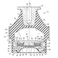
- FIG. 3 is a longitudinal sectional view showing an engine mount as one embodiment of the present invention, and is a view corresponding to the II section of FIG. 2.
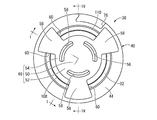
- the bottom view of the partition member shown by FIG. FIG. 4 is a sectional view taken along line IV-IV in FIG. 2.
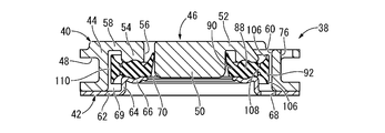
- FIG. 3 is a longitudinal sectional view showing an enlarged main part of the partition member shown in FIG. 2, where (a) shows an input state of vibration corresponding to engine shake, and (b) shows vibration corresponding to vibration during idling. (C) shows a state where an excessive negative pressure is applied to the pressure receiving chamber.
- FIG. 1 shows an engine mount 10 for an automobile as an embodiment of a fluid-filled vibration isolator constructed according to the present invention.
- the engine mount 10 has a structure in which a first mounting member 12 and a second mounting member 14 are connected by a main rubber elastic body 16.
- the vertical direction means, in principle, the vertical direction in FIG. 1, which is the main vibration input direction.
- the first mounting member 12 is a high-rigidity member having a small-diameter, generally cylindrical shape, and includes a flange portion 18 that protrudes from the upper end in the axial direction to the outer peripheral side. Further, the first mounting member 12 is formed with a bolt hole 20 extending on the central axis. The bolt hole 20 is open on the upper surface and is threaded on the inner peripheral surface.
- the second mounting member 14 is a highly rigid member having a thin, large-diameter, generally cylindrical shape, and a step portion 22 is provided in the middle in the axial direction, and the upper side in the axial direction across the step portion 22 is large.
- the diameter cylinder portion 24 is used, and the lower side in the axial direction is a small diameter cylinder portion 26, thereby forming a stepped cylinder as a whole.
- the entire second attachment member 14 is a cylindrical portion.
- the first mounting member 12 is disposed on the same central axis in the upper opening of the second mounting member 14, and the first mounting member 12 and the second mounting member 14 are the main rubber elastic body 16. It is elastically connected by.
- the main rubber elastic body 16 has a thick-walled large-diameter substantially truncated cone shape, the first mounting member 12 is vulcanized and bonded to the small-diameter end, and the outer peripheral surface of the large-diameter end.
- the inner peripheral surface of the second mounting member 14 is overlapped and vulcanized and bonded.
- the main rubber elastic body 16 is formed as an integrally vulcanized molded product including the first mounting member 12 and the second mounting member 14.
- the main rubber elastic body 16 is formed with a large-diameter recess 28 that is open in the large-diameter side end surface (lower surface) in a reverse mortar shape. Further, from the outer peripheral side of the large-diameter recess 28 in the main rubber elastic body 16, a seal rubber layer 30 is integrally formed and extends downward.
- the seal rubber layer 30 is a rubber elastic body having a thin-walled, large-diameter, generally cylindrical shape, and has an outer peripheral surface superimposed on an inner peripheral surface of the small-diameter cylindrical portion 26 of the second mounting member 14 and vulcanized. As a result, the entire surface of the second mounting member 14 is covered with a rubber elastic body.
- a flexible film 32 is attached to the lower opening of the second attachment member 14.
- the flexible film 32 is a thin rubber film having a substantially disk shape or a circular dome shape, and has a sufficient slack in the vertical direction.
- the outer peripheral surface of the flexible film 32 is vulcanized and bonded to a fixing member 34 having a substantially cylindrical shape or an annular shape. Then, after the fixing member 34 is inserted into the lower opening of the second mounting member 14, the second mounting member 14 is subjected to diameter reduction processing such as an eight-way drawing, whereby the fixing member 34 is The flexible film 32 is supported by the second mounting member 14.
- the upper opening of the second mounting member 14 is closed by the main rubber elastic body 16, and the lower opening of the second mounting member 14 is closed by the flexible film 32.
- a fluid sealing region 36 is formed between the main rubber elastic body 16 and the flexible film 32.
- the fluid sealing area 36 is sealed from the outside, and incompressible fluid is sealed therein.
- the incompressible fluid sealed in the fluid sealing region 36 is not particularly limited.
- water, alkylene glycol, polyalkylene glycol, silicone oil, or a mixed solution thereof is preferably used. Is done.
- a low viscosity fluid of 0.1 Pa ⁇ s or less is desirable.
- a partition member 38 is disposed in the fluid sealing region 36. As shown in FIGS. 2 to 4, the partition member 38 has a thick and large-diameter substantially disk shape, and includes a partition member main body 40 and a bottom plate member 42.
- the partition member main body 40 is a high-rigidity member having a substantially thick and large-diameter disk as a whole, and is inserted into the annular outer peripheral portion 44 and the central hole of the outer peripheral portion 44 at a predetermined distance in the radial direction.
- the arranged central portions 46 have a structure in which the upper ends are connected to each other by an outer peripheral connecting portion 58 described later.
- the outer peripheral portion 44 has a large-diameter annular shape that continuously extends in the circumferential direction over the entire circumference.
- the outer peripheral portion 44 has a circumference that opens to the outer peripheral surface and extends a little less than one round.
- a groove 48 is formed.
- the central portion 46 disposed in the central hole of the outer peripheral portion 44 has a columnar central abutting portion 50, and a flange-shaped inner peripheral connecting portion 52 is integrated with the upper end of the central abutting portion 50.
- the outer peripheral end portion of the inner peripheral connection portion 52 is provided with a sandwiching protrusion 54 that protrudes downward over the entire periphery.
- the inner peripheral coupling portion 52 is formed with upper through holes 56 having a predetermined length in the circumferential direction at a plurality of locations on the circumference (three locations in the present embodiment). It penetrates in the vertical direction.
- the central portion 46 is inserted into the central hole of the outer peripheral portion 44, and the inner peripheral surface of the outer peripheral portion 44 and the outer peripheral surface of the central portion 46 are opposed to each other with a predetermined distance. Further, the outer peripheral portion 44 and the central portion 46 have an integrated structure that is connected to each other at the upper end portion by outer peripheral connecting portions 58 provided at a plurality of locations on the periphery (three locations in the present embodiment).
- a partition member body 40 having a portion 44 and a central portion 46 is configured.
- An upper communication hole 60 is formed between the outer peripheral coupling portions 58 in the circumferential direction, and is provided so as to penetrate in the axial direction with a predetermined length in the circumferential direction.
- the bottom plate member 42 is a high-rigidity plate material having a substantially annular plate shape as a whole, and is a cylindrical shape that protrudes upward at the inner peripheral edge portion of the outer peripheral support portion 62 having a substantially annular plate shape.
- the step portion 64 is provided, and an inner flange-shaped clamping piece 66 protruding from the upper end of the step portion 64 toward the inner peripheral side is integrally formed.
- a plurality of lower communication holes 68 having a predetermined length in the circumferential direction are provided in the inner circumferential portion of the outer circumferential support portion 62 so as to penetrate in the thickness direction.
- the bottom plate member 42 has an outer diameter dimension that is substantially the same as the outer diameter dimension of the partition member body 40 and an inner diameter dimension that is substantially the same as the inner diameter dimension of the clamping protrusion 54 of the partition member body 40. The diameter is larger than that of the central contact portion 50.
- the partition member main body 40 and the bottom plate member 42 are overlapped in the axial direction and fixed to each other by means such as locking or adhesion.
- the partition member main body 40 and the bottom plate member 42 are separated from each other in the axial direction between the outer peripheral portion 44 of the partition member main body 40 and the central contact portion 50, and these partition member main bodies 40 are separated from each other in the axial direction.
- An annular accommodation space 69 is formed between the axially opposed surfaces of the bottom plate member 42 and the bottom plate member 42.
- the center contact portion 50 of the partition member main body 40 is inserted into the center hole of the bottom plate member 42, and an annular lower through hole 70 is formed between the center contact portion 50 and the clamping piece 66 of the bottom plate member 42. Is formed.
- the partition member 38 having such a structure is accommodated in the fluid sealing region 36 and supported by the second mounting member 14. More specifically, the partition member 38 is inserted into the small diameter cylindrical portion 26 of the second mounting member 14, and the outer peripheral portion of the partition member 38 is superimposed on the lower end surface of the main rubber elastic body 16 and positioned in the axial direction. After that, the second mounting member 14 is fixed to the second mounting member 14 together with the fixing member 34 by reducing the diameter of the second mounting member 14. As a result, the partition member 38 is supported so that the outer peripheral portion is supported by the second mounting member 14, and is disposed so as to spread in the direction perpendicular to the axis within the fluid sealing region 36.
- the fluid sealing region 36 is vertically divided into two with the partition member 38 interposed therebetween.
- a part of the wall portion is constituted by the main rubber elastic body 16, and a pressure receiving chamber 72 in which an internal pressure fluctuation is exerted when vibration is input is formed, and the partition member 38.
- a part of the wall portion is formed of the flexible film 32, and an equilibrium chamber 74 in which volume change is easily allowed is formed.
- the pressure receiving chamber 72 and the equilibrium chamber 74 are filled with an incompressible fluid sealed in the fluid sealing region 36.
- the outer peripheral surface of the partition member 38 is overlapped with the inner peripheral surface of the second mounting member 14 via the seal rubber layer 30.
- the outer peripheral opening of the circumferential groove 48 is fluid-tightly closed by the second mounting member 14 to form a tunnel-like flow path extending in the circumferential direction.
- One end portion of the tunnel-shaped flow path communicates with the pressure receiving chamber 72 through the first communication hole 76, and the other end portion communicates with the equilibrium chamber 74 through the second communication hole 78.
- a first orifice passage 80 is formed to communicate the equilibrium chamber 74 with each other.
- the first orifice passage 80 is adjusted by adjusting the ratio (A / L) of the passage sectional area (A) to the passage length (L) in consideration of the wall spring rigidity of the pressure receiving chamber 72 and the equilibrium chamber 74.
- the frequency is tuned to a low frequency of about 10 Hz corresponding to the engine shake.
- a second orifice passage 82 is formed between the central portion 46 and the outer peripheral portion 44 in the radial direction. That is, an annular region between the central portion 46 and the outer peripheral portion 44 in the accommodation space 69 between the radial direction communicates with the pressure receiving chamber 72 through the upper communication hole 60 provided between the outer peripheral connecting portions 58 in the circumferential direction. It communicates with the equilibrium chamber 74 through a lower communication hole 68 formed in the bottom plate member 42. As a result, a second orifice passage 82 is formed to communicate the pressure receiving chamber 72 and the equilibrium chamber 74 with each other.
- the second orifice passage 82 has a tuning frequency set higher than that of the first orifice passage 80.
- the second orifice passage 82 is tuned to a medium to high frequency of 10 or more Hz corresponding to vibration during idling or traveling noise. Has been.
- a region between the central contact portion 50 and the holding protrusion 54 in the accommodation space 69 between the radial direction is communicated with the pressure receiving chamber 72 through the upper through hole 56 penetrating the inner peripheral connection portion 52, and It communicates with the equilibrium chamber 74 through a lower through hole 70 provided between the contact portion 50 and the bottom plate member 42 in the radial direction.
- a short-circuit passage 84 (described later) that connects the pressure receiving chamber 72 and the equilibrium chamber 74 to each other is formed in the partition member 38 so as to penetrate between the radial direction of the central contact portion 50 and the sandwiching protrusion 54. (See FIG. 7 (c)).
- the ratio of the passage cross-sectional area to the passage length is set to be larger than that of the second orifice passage 82, and the flow resistance is made smaller than those of the first and second orifice passages 80 and 82. It is desirable.
- an elastic movable body 86 is disposed in the accommodation space 69 formed in the partition member 38.
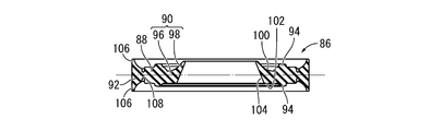
- the elastic movable body 86 is a member that is formed of a rubber elastic body and has a substantially annular shape or an annular plate shape, and includes an annular sandwiching portion 88 and a sandwiching portion 88.
- a valve portion 90 provided on the inner peripheral side of the first and second switching portions 92 provided on the outer peripheral side of the clamping portion 88.
- the sandwiching portion 88 has an annular shape that continuously extends with a substantially constant cross-sectional shape over the entire circumference, and has a shape in which a substantially circular inner peripheral portion and a substantially rectangular outer peripheral portion are combined in a vertical cross section. .
- compression protrusions 94 that protrude on both sides in the axial direction are integrally formed on the inner peripheral portion of the clamping portion 88.
- the outer peripheral surface of the clamping part 88 is made into the cylindrical shape extended in a substantially axial direction.
- a valve portion 90 is integrally formed on the inner peripheral side of the clamping portion 88.
- the valve portion 90 extends with a substantially constant cross-sectional shape over the entire circumference, and protrudes from the holding portion 88 toward the inner peripheral side and expands in a direction substantially perpendicular to the axis, and from the outer peripheral base end portion 96 to the inner side. It has an inner peripheral front end 98 that protrudes to the peripheral side.
- the upper surfaces of the outer peripheral base end portion 96 and the inner peripheral front end portion 98 are formed by a smooth curved concave surface 100, while the lower surface of the outer peripheral base end portion 96 is formed by an axial straight plane 102 extending in a direction substantially perpendicular to the axis.
- the lower surface of the inner peripheral tip portion 98 is constituted by a tapered surface 104 that gradually inclines as it goes to the inner peripheral side.
- the outer peripheral base end portion 96 is made slightly thicker toward the inner peripheral side and expands in a direction substantially perpendicular to the axis, and the inner peripheral distal end portion 98 gradually becomes thinner toward the inner peripheral side. It has a tapered shape that gradually inclines upward as it goes to the inner peripheral side.
- the valve portion 90 has an outer peripheral portion that is thicker than the inner peripheral portion because the inner peripheral tip portion 98 is thinner toward the protruding tip side.
- the thickness dimension of the outermost periphery part of the valve part 90 is made smaller than the maximum thickness dimension (diameter of the circular inner peripheral part in a longitudinal cross section) of the clamping part 88.
- FIG. since the upper surface of the valve portion 90 is configured by the curved concave surface 100 that is gradually inclined upward toward the inner peripheral side, a valley line is formed at the boundary between the clamping portion 88 and the valve portion 90 on the upper surface.
- a switching unit 92 is provided on the outer peripheral side of the clamping unit 88.
- the switching portion 92 has an annular shape that continuously extends with a substantially constant cross-sectional shape over the entire circumference, and the inner peripheral surface and the outer peripheral surface are concentric cylindrical surfaces, and as it goes to the outer peripheral side. It gradually becomes thick.
- the switching unit 92 is configured by a concave curved surface in which both sides in the axial direction increase in inclination angle with respect to the direction perpendicular to the axis toward the outer peripheral side, and the outermost end projects most greatly on both sides in the axial direction.
- a contact portion 106 is provided.
- the contact portion 106 is gradually narrower in the radial direction as it goes outward in the axial direction (protruding tip side), and the protruding tip surface is formed by an arcuate curved surface.
- the switching portion 92 including the abutting portion 106 has a line-symmetric shape with respect to the center line in the thickness direction (indicated by a one-dot chain line in FIG. 5) in the longitudinal section.
- the switching portion 92 is connected to the sandwiching portion 88 via the thin portion 108 and is integrally formed with the sandwiching portion 88.
- the thin-walled portion 108 is provided at a central portion in the axial direction between the outer peripheral surface of the holding portion 88 and the inner peripheral surface of the switching portion 92, and the outer peripheral end portion of the holding portion 88 and the inner peripheral end of the switching portion 92. Thinner than any of the parts. Thereby, the switching unit 92 is allowed to tilt with respect to the clamping unit 88 due to elastic deformation of the thin portion 108.
- the thin portion 108 is narrow in the radial direction, and the outer peripheral surface of the sandwiching portion 88 and the inner peripheral surface of the switching portion 92 are opposed to each other with a short separation distance in the radial direction.
- the inner peripheral surface of the switching portion 92 comes into contact with the outer peripheral surface of the holding portion 88 on the outer side in the axial direction of the thin portion 108.
- the defining means for defining the relative amount of tilting of the switching unit 92 with respect to the clamping unit 88 is configured by contact between the clamping unit 88 and the thin portion 108 of the switching unit 92.
- the elastic movable body 86 having such a structure is disposed between the partition member main body 40 and the bottom plate member 42 (see FIG. 6). That is, the sandwiching portion 88 of the elastic movable body 86 is disposed between the axially facing surfaces of the sandwiching protrusion 54 of the partition member main body 40 and the sandwiching piece 66 of the bottom plate member 42, and the sandwiching protrusion 54 and the sandwiching piece 66. Are supported by being sandwiched between them in the axial direction. At this time, the compression protrusion 94 integrally formed on the sandwiching portion 88 is greatly compressed between the sandwiching projection 54 and the sandwiching piece 66, so that the positioning action of the elastic movable body 86 on the partition member 38 is sufficiently large. Has been.
- valve portion 90 of the elastic movable body 86 is disposed between the clamping protrusion 54 and the central contact portion 50 in the radial direction, protrudes inward from the bottom plate member 42, and the central contact portion 50. It is pressed against the outer peripheral surface of. Thereby, in a stationary state without vibration input, the valve portion 90 is disposed on the fluid flow path of the short-circuit passage 84, and the short-circuit passage 84 is blocked by the valve portion 90. Further, the pressure of the pressure receiving chamber 72 is applied to the upper surface of the valve portion 90 through the short-circuit passage 84 (upper through-hole 56), and the lower surface of the valve portion 90 is connected to the lower surface through the short-circuit passage 84 (lower through-hole 70).
- valve part 90 may contact
- the switching portion 92 of the elastic movable body 86 is disposed between the outer peripheral portion 44 and the central portion 46 in the radial direction, and is disposed on the fluid flow path of the second orifice passage 82. Further, the outer peripheral surface of the switching portion 92 is disposed to face the inner peripheral surface of the outer peripheral portion 44 at a predetermined distance radially inward, and the outer peripheral surface of the switching portion 92 and the inner peripheral surface of the outer peripheral portion 44 are arranged. Between these radial directions, an annular gap 110 extending continuously in the axial direction is formed. Thereby, in the stationary state without vibration input, the second orifice passage 82 is in communication with the gap 110.
- the upper surface of the switching unit 92 is subjected to the hydraulic pressure of the pressure receiving chamber 72 through the second orifice passage 82 (upper communication hole 60), and the lower surface of the switching unit 92 is provided with the second orifice passage 82 (lower side).
- the fluid pressure in the equilibrium chamber 74 is exerted through the side communication hole 68).
- the contact portion 106 provided in the switching portion 92 protrudes in the passage length direction (vertical direction in FIG. 1) of the second orifice passage 82, so that the second orifice passage 82 is in a communicating state without being blocked by the contact portion 106.
- the first attachment member 12 is attached to a power unit (not shown), and the second attachment member 14 is attached to a vehicle body (not shown).
- the vehicle body is supported by vibration isolation via the mount 10.
- the pressure receiving chamber 72 When low-frequency large-amplitude vibration corresponding to an engine shake is input in a state where the engine mount 10 is mounted on the vehicle, the pressure receiving chamber 72 is balanced with the pressure receiving chamber 72 based on the relative internal pressure fluctuation with respect to the balancing chamber 74. Fluid flows between the chambers 74 through the first orifice passage 80. As a result, based on a fluid action such as a resonance action of the fluid, a target vibration isolation effect (high damping effect) is exhibited.
- the switching unit 92 blocks the second orifice passage 82 as shown in FIG. That is, when a low-frequency large-amplitude vibration corresponding to an engine shake is input, the thin portion 108 is elastically deformed based on the hydraulic pressure difference between the pressure receiving chamber 72 and the equilibrium chamber 74, and the sandwiching portion 88 is interposed via the thin portion 108.
- the switching portion 92 connected to the tilt portion is tilted with respect to the sandwiching portion 88.
- the outer peripheral surface of the contact portion 106 protruding from the switching portion 92 in the passage length direction (vertical direction in FIG. 1) of the second orifice passage 82 constitutes the inner surface of the second orifice passage 82.
- the amount of tilting of the switching portion 92 relative to the sandwiching portion 88 is defined by the inner peripheral surface of the switching portion 92 and the outer peripheral surface of the sandwiching portion 88 abutting on the axially outer side of the thin portion 108.
- a defining means is provided.
- the second orifice passage 82 has a contact portion 106 of the switching portion 92 as shown in FIG.
- the pressure receiving chamber 72 and the equilibrium chamber 74 are brought into a communicating state.
- the fluid flow through the second orifice passage 82 is positively induced, and a target vibration-proof effect (low dynamic spring effect) is exhibited based on the fluid flow action.
- the switching unit that switches between communication and blocking of the second orifice passage 82 is configured by using the tilt of the switching unit 92 according to the amplitude of the input vibration.
- the first orifice passage 80 tuned to a frequency lower than the input vibration is substantially cut off by anti-resonance or the like, so that the amount of fluid flow through the second orifice passage 82 is efficiently ensured.
- the vibration isolation effect by the first orifice passage 80 and the vibration isolation effect by the second orifice passage 82 are input. It is exhibited selectively according to the frequency of vibration. Moreover, an effective anti-vibration effect can be obtained by the switching unit 92 functioning as a movable film even with respect to vibration having a frequency higher than the tuning frequency of the second orifice passage 82. Therefore, the engine mount 10 can obtain an excellent anti-vibration effect against vibrations in a wide frequency range.
- the switching portion 92 is tilted relative to the clamping portion 88 due to the hydraulic pressure acting in the axial direction, the abutting portion 106 abuts against the inner surface of the second orifice passage 82.
- the direction and the contact direction of the contact portion 106 with respect to the inner surface of the second orifice passage 82 are different from each other. Therefore, the impact force is reduced at the time of contact between the contact portion 106 and the inner surface of the second orifice passage 82, and the occurrence of contact hitting sound is prevented.
- the tilt limiting action based on the elasticity of the thin portion 108 is exerted more strongly, and the tilting speed of the switching unit 92 is reduced.
- the amount of tilting of the switching portion 92 is sufficiently large. Impact force is reduced. Therefore, generation of a hitting sound due to the contact of the contact portion 106 with the inner surface of the second orifice passage 82 is prevented.
- the contact portion 106 is provided at the outer peripheral end portion of the switching portion 92, the diameter of the gap 110 is increased without increasing the amount of tilting of the switching portion 92 required for blocking the second orifice passage 82.
- a large direction width can be secured. Therefore, the substantial passage cross-sectional area of the second orifice passage 82 can be ensured to be large with excellent space efficiency, and the degree of freedom of tuning of the second orifice passage 82 can be increased.
- the switching portion 92 becomes gradually thicker toward the outer peripheral side, and accordingly, the contact portion 106 becomes gradually narrower toward the protruding tip side.
- the contact portion 106 contacts the inner surface of the second orifice passage 82, the contact portion 106 gradually contacts from the front end side of the narrow width, so that the occurrence of hitting sound is likely to be a problem. The impact force is reduced, and the occurrence of hitting sound is prevented. Further, the amount of contact of the contact portion 106 with the inner surface of the second orifice passage 82 increases, and the contact portion gradually spreads toward the wide base end side. Therefore, the switching portion 92 is stably held at the blocking position of the second orifice passage 82.
- the engine mount 10 is provided with a defining means using contact between the inner peripheral surface of the switching portion 92 and the outer peripheral surface of the clamping portion 88, and in cooperation with the elasticity of the contact portion 106, the switching portion 92 is provided.
- the amount of tilting is defined.
- the elastic movable body 86 is an annular body and the clamping portion 88 is continuously provided over the entire circumference, the elastic movable body 86 is stably provided between the partition member main body 40 and the bottom plate member 42. Sandwiched between. Furthermore, since the switching portion 92 is continuously provided over the entire circumference, it is easy to ensure fluid tightness when the second orifice passage 82 is blocked, and the partition member 38 needs to be enlarged. In other words, a large cross-sectional area of the second orifice passage 82 can be secured.
- the short-circuit passage 84 that communicates the pressure-receiving chamber 72 and the equilibrium chamber 74 with each other is communicated, and fluid flows into the pressure-receiving chamber 72 from the equilibrium chamber 74 through the short-circuit passage 84, so that the negative pressure in the pressure-receiving chamber 72 is quickly increased. Reduction or elimination. As a result, the generation of bubbles due to cavitation is suppressed and the shock wave generated when the bubbles disappear is reduced, so that cavitation noise is reduced or prevented.
- the short-circuit passage 84 is set such that the ratio (A / L) of the passage cross-sectional area (A) to the passage length (L) is set to be larger than that of the second orifice passage 82, and the fluid flow resistance is the first and second. It is made smaller than the second orifice passages 80 and 82.
- the relief means includes a short-circuit passage 84 that communicates the pressure-receiving chamber 72 and the equilibrium chamber 74, and a valve portion 90 that switches communication and disconnection between the short-circuit passage 84.
- valve portion 90 constituting the relief means is provided integrally with the elastic movable body 86, an increase in the number of parts due to the provision of the relief means is prevented, and an increase in the number of steps for assembling the parts, etc. Is also avoided.
- valve portion 90 is not essential in the elastic movable body, and the elastic movable body is constituted by the holding portion 88 supported by the partition member 38 and the switching portion 92 provided integrally with the holding portion 88 via the thin portion 108. May be configured. In this case, it goes without saying that the short-circuit passage 84 provided in the partition member 38 in the embodiment is unnecessary.
- the shape of the contact portion 106 provided in the switching portion 92 is not limited to the shape that gradually becomes narrower toward the distal end side as shown in the above-described embodiment, and for example, from the proximal end portion to the distal end portion It may have a substantially constant width dimension. Further, the abutting portion 106 does not necessarily have to be provided at the outer peripheral end portion of the switching portion 92, and may be provided at the radial middle or inner peripheral end portion of the switching portion 92.
- the elastic movable body is not necessarily limited to a ring shape or a ring plate shape.
- the sandwiching part and the switching part constituting the elastic movable body are not limited to the annular shape.
- the switching part is provided only on the fluid flow path of the second orifice passage 82 provided partially on the circumference. It may be arranged and may be less than one round on the circumference.
- the thin portion 108 be narrow in the radial direction to constitute a defining means for defining the tilting amount of the switching portion 92.
- the radial direction dimension (width dimension) of the thin portion 108 is increased.
- the switching unit 92 may be easily tilted.
- the width dimension of the thin wall portion 108 is appropriately set according to the required performance, so that the outer peripheral surface of the sandwiching portion 88 and the inner peripheral surface of the switching portion 92 are always brought into contact with each other. It does not have to be set.
- the present invention is not necessarily applied only to the engine mount, but can be applied to a body mount, a subframe mount, a differential mount, and the like.
- the fluid-filled vibration isolator of the present invention is not limited to automobiles, and can be suitably employed for motorcycles, railway vehicles, industrial vehicles, and the like.
- 10 engine mount (fluid-filled vibration isolator), 12: first mounting member, 14: second mounting member, 16: main rubber elastic body, 32: flexible membrane, 38: partition member, 72: Pressure receiving chamber, 74: equilibrium chamber, 80: first orifice passage, 82: second orifice passage, 84: short-circuit passage, 86: elastic movable body, 88: clamping portion, 90: valve portion, 92: switching portion, 104: Tapered surface (valve inner peripheral surface), 106: contact portion, 108: thin-walled portion, 110: gap
Landscapes
- Engineering & Computer Science (AREA)
- General Engineering & Computer Science (AREA)
- Mechanical Engineering (AREA)
- Combined Devices Of Dampers And Springs (AREA)
Abstract
Description
Claims (6)
- 第1の取付部材と筒状部を有する第2の取付部材が本体ゴム弾性体によって弾性連結されていると共に、該第2の取付部材によって支持される仕切部材を挟んだ両側に壁部の一部が該本体ゴム弾性体で構成された受圧室と壁部の一部が可撓性膜で構成された平衡室が形成されており、それら受圧室と平衡室に非圧縮性流体が封入されていると共に、それら受圧室と平衡室を相互に連通する第1のオリフィス通路と第2のオリフィス通路が形成されて、該第2のオリフィス通路が該第1のオリフィス通路よりも高周波数にチューニングされている流体封入式防振装置において、
前記仕切部材には弾性可動体が取り付けられており、該弾性可動体が該仕切部材で挟まれる挟持部を有していると共に、該挟持部の外周側には前記第2のオリフィス通路の流体流路上に位置する切替部が設けられており、該切替部の両面に前記受圧室の液圧と前記平衡室の液圧の各一方が及ぼされていると共に、該切替部には該第2のオリフィス通路の通路長方向で両側に突出する当接部が形成されている一方、該挟持部と該切替部の間に設けられた薄肉部の弾性変形によって該切替部の該挟持部に対する相対的な傾動が許容されており、該切替部の外周面と該第2のオリフィス通路の内面との間に形成された隙間を通じて該第2のオリフィス通路を連通すると共に該受圧室と該平衡室の相対的な圧力変動に基づいて該切替部が該挟持部に対して該薄肉部を中心として相対的に傾動されて該切替部の該当接部の外周面が該第2のオリフィス通路の内面に当接されることによって該第2のオリフィス通路を遮断する切替手段が構成されていることを特徴とする流体封入式防振装置。 - 前記弾性可動体が環状とされており、前記挟持部および前記切替部が何れも全周に亘って連続的に設けられている請求項1に記載の流体封入式防振装置。
- 前記薄肉部が狭幅とされており、前記切替部と前記挟持部が該薄肉部において当接することによってそれら切替部と挟持部の相対的な傾動量を規定する規定手段が構成されている請求項1又は2に記載の流体封入式防振装置。
- 前記当接部が前記切替部の外周端部に設けられている請求項1~3の何れか1項に記載された流体封入式防振装置。
- 前記切替部が外周側に行くに従って次第に厚肉とされており、前記当接部が突出先端側に行くに従って次第に狭幅とされている請求項4に記載の流体封入式防振装置。
- 前記挟持部の内周側に弁部が一体形成されていると共に、前記仕切部材に形成されて前記受圧室と前記平衡室を相互に連通する短絡通路上に該弁部が配置されており、該弁部の内周面が該短絡通路の内面に当接されることで該短絡通路を遮断すると共に該受圧室の負圧が該弁部に作用して該弁部が該短絡通路の内面から離隔するように弾性変形することで該受圧室と該平衡室の間で該短絡通路を通じて流体流動を許容するリリーフ手段が設けられている請求項1~5の何れか1項に記載の流体封入式防振装置。
Priority Applications (3)
| Application Number | Priority Date | Filing Date | Title |
|---|---|---|---|
| CN201280001321.2A CN102906450B (zh) | 2011-05-23 | 2012-05-22 | 流体封入式隔振装置 |
| DE112012000231.8T DE112012000231B4 (de) | 2011-05-23 | 2012-05-22 | Fluid-gefüllte Schwingungssteuervorrichtung |
| US13/677,650 US8783668B2 (en) | 2011-05-23 | 2012-11-15 | Fluid-filled type vibration damping device |
Applications Claiming Priority (2)
| Application Number | Priority Date | Filing Date | Title |
|---|---|---|---|
| JP2011-114388 | 2011-05-23 | ||
| JP2011114388A JP5396431B2 (ja) | 2011-05-23 | 2011-05-23 | 流体封入式防振装置 |
Related Child Applications (1)
| Application Number | Title | Priority Date | Filing Date |
|---|---|---|---|
| US13/677,650 Continuation US8783668B2 (en) | 2011-05-23 | 2012-11-15 | Fluid-filled type vibration damping device |
Publications (1)
| Publication Number | Publication Date |
|---|---|
| WO2012160805A1 true WO2012160805A1 (ja) | 2012-11-29 |
Family
ID=47216897
Family Applications (1)
| Application Number | Title | Priority Date | Filing Date |
|---|---|---|---|
| PCT/JP2012/003328 Ceased WO2012160805A1 (ja) | 2011-05-23 | 2012-05-22 | 流体封入式防振装置 |
Country Status (5)
| Country | Link |
|---|---|
| US (1) | US8783668B2 (ja) |
| JP (1) | JP5396431B2 (ja) |
| CN (1) | CN102906450B (ja) |
| DE (1) | DE112012000231B4 (ja) |
| WO (1) | WO2012160805A1 (ja) |
Cited By (3)
| Publication number | Priority date | Publication date | Assignee | Title |
|---|---|---|---|---|
| DE102012217427A1 (de) * | 2012-09-26 | 2014-05-28 | Bayerische Motoren Werke Aktiengesellschaft | Hydrolager, insbesondere Aggregatlager für ein Kraftfahrzeug |
| CN105757160A (zh) * | 2015-01-07 | 2016-07-13 | 住友理工株式会社 | 流体封入式隔振装置 |
| WO2016175273A1 (ja) * | 2015-04-28 | 2016-11-03 | 山下ゴム株式会社 | 防振装置 |
Families Citing this family (23)
| Publication number | Priority date | Publication date | Assignee | Title |
|---|---|---|---|---|
| JP5916550B2 (ja) * | 2012-07-19 | 2016-05-11 | 住友理工株式会社 | 流体封入式防振装置 |
| US20150046031A1 (en) * | 2013-08-07 | 2015-02-12 | Honda Motor Co., Ltd. | Switchable Mount System For A Vehicle And Methods For Controlling The System |
| JP6240482B2 (ja) * | 2013-11-25 | 2017-11-29 | 住友理工株式会社 | 流体封入式防振装置 |
| JP6306412B2 (ja) * | 2014-04-18 | 2018-04-04 | 山下ゴム株式会社 | 液封防振装置 |
| DE102014108840B4 (de) * | 2014-06-24 | 2019-05-09 | Vibracoustic Gmbh | Entkoppeltes Hydrolager |
| DE102016206946A1 (de) * | 2016-04-25 | 2017-10-26 | Contitech Vibration Control Gmbh | Hydrolager, insbesondere schaltbares oder steuerbares Hydrolager |
| US11448286B2 (en) * | 2017-04-27 | 2022-09-20 | Prospira Corporation | Vibration-damping device |
| DE102017112168B4 (de) * | 2017-06-01 | 2021-04-29 | Vibracoustic Gmbh | Trennvorrichtung zum Trennen einer Arbeitskammer und einer Ausgleichskammer eines hydraulisch dämpfenden Lagers sowie ein hydraulisch dämpfendes Lager |
| KR102451984B1 (ko) * | 2017-10-31 | 2022-10-06 | 현대자동차주식회사 | 자동차용 유체 봉입형 마운트 |
| DE102018102130A1 (de) * | 2018-01-31 | 2019-08-01 | Vibracoustic Gmbh | Hydraulisch dämpfendes Lager |
| JP6956658B2 (ja) | 2018-03-14 | 2021-11-02 | 住友理工株式会社 | 流体封入式防振装置 |
| US11959527B2 (en) * | 2018-05-10 | 2024-04-16 | Prospira Corporation | Vibration isolator |
| CN112105837B (zh) * | 2018-08-24 | 2022-04-26 | 住友理工株式会社 | 流体封入式防振装置 |
| CN112576681B (zh) * | 2019-09-27 | 2023-02-24 | 现代自动车株式会社 | 用于车辆的悬置 |
| JP7269146B2 (ja) * | 2019-10-18 | 2023-05-08 | 住友理工株式会社 | 流体封入式防振装置 |
| US12196284B2 (en) | 2019-11-07 | 2025-01-14 | Prospira Corporation | Vibration-damping device |
| WO2021090886A1 (ja) | 2019-11-07 | 2021-05-14 | 株式会社ブリヂストン | 防振装置 |
| JP7350629B2 (ja) | 2019-11-07 | 2023-09-26 | 株式会社プロスパイラ | 防振装置 |
| CN114728573B (zh) | 2019-11-07 | 2025-11-04 | 株式会社普洛斯派 | 隔振装置 |
| KR102855175B1 (ko) * | 2020-03-31 | 2025-09-03 | 현대자동차주식회사 | 자동차용 엔진마운트 |
| KR102846969B1 (ko) * | 2020-04-08 | 2025-08-18 | 현대자동차주식회사 | 엔진 마운트 |
| JP7438000B2 (ja) * | 2020-04-08 | 2024-02-26 | Toyo Tire株式会社 | 液封入式防振装置 |
| JP7487092B2 (ja) * | 2020-12-21 | 2024-05-20 | 住友理工株式会社 | 流体封入式防振装置 |
Citations (4)
| Publication number | Priority date | Publication date | Assignee | Title |
|---|---|---|---|---|
| JP2001200883A (ja) * | 2000-01-20 | 2001-07-27 | Kinugawa Rubber Ind Co Ltd | 液体封入式防振装置 |
| JP2007051713A (ja) * | 2005-08-18 | 2007-03-01 | Nissan Motor Co Ltd | 液封入式防振装置 |
| JP2009138847A (ja) * | 2007-12-06 | 2009-06-25 | Tokai Rubber Ind Ltd | 流体封入式防振装置 |
| WO2011145656A1 (ja) * | 2010-05-19 | 2011-11-24 | 山下ゴム株式会社 | 液封防振装置 |
Family Cites Families (13)
| Publication number | Priority date | Publication date | Assignee | Title |
|---|---|---|---|---|
| FR2812362B1 (fr) * | 2000-07-28 | 2003-02-07 | Hutchinson | Support antivibratoire hydraulique et son procede de fabrication |
| WO2002081944A1 (fr) * | 2001-03-30 | 2002-10-17 | Toyo Tire & Rubber Co., Ltd. | Amortisseur de vibration de type a liquide etanche |
| JP3783100B2 (ja) * | 2001-08-07 | 2006-06-07 | 東洋ゴム工業株式会社 | 液封入式防振装置 |
| JP2007155033A (ja) | 2005-12-06 | 2007-06-21 | Tokai Rubber Ind Ltd | 吊下型流体封入式防振装置 |
| JP2007270910A (ja) | 2006-03-30 | 2007-10-18 | Tokai Rubber Ind Ltd | 流体封入式防振装置 |
| JP2008002618A (ja) * | 2006-06-23 | 2008-01-10 | Tokai Rubber Ind Ltd | 流体封入式防振装置 |
| US8490954B2 (en) * | 2006-12-05 | 2013-07-23 | Yamashita Rubber Kabushiki Kaisha | Liquid sealed vibration isolating device |
| JP5170809B2 (ja) * | 2007-08-27 | 2013-03-27 | 山下ゴム株式会社 | 液封防振装置 |
| JP2009243511A (ja) * | 2008-03-28 | 2009-10-22 | Tokai Rubber Ind Ltd | 自動車用の流体封入式エンジンマウント |
| WO2010001543A1 (ja) * | 2008-06-30 | 2010-01-07 | 東海ゴム工業株式会社 | 流体封入式防振装置 |
| CN102265059B (zh) | 2008-12-25 | 2013-08-07 | 东海橡塑工业株式会社 | 流体封入式隔振装置 |
| JP5256152B2 (ja) * | 2009-09-16 | 2013-08-07 | 東海ゴム工業株式会社 | 流体封入式防振装置 |
| US8651467B2 (en) * | 2010-08-31 | 2014-02-18 | Tokai Rubber Industries, Ltd. | Fluid-filled type vibration damping device |
-
2011
- 2011-05-23 JP JP2011114388A patent/JP5396431B2/ja active Active
-
2012
- 2012-05-22 DE DE112012000231.8T patent/DE112012000231B4/de active Active
- 2012-05-22 WO PCT/JP2012/003328 patent/WO2012160805A1/ja not_active Ceased
- 2012-05-22 CN CN201280001321.2A patent/CN102906450B/zh active Active
- 2012-11-15 US US13/677,650 patent/US8783668B2/en active Active
Patent Citations (4)
| Publication number | Priority date | Publication date | Assignee | Title |
|---|---|---|---|---|
| JP2001200883A (ja) * | 2000-01-20 | 2001-07-27 | Kinugawa Rubber Ind Co Ltd | 液体封入式防振装置 |
| JP2007051713A (ja) * | 2005-08-18 | 2007-03-01 | Nissan Motor Co Ltd | 液封入式防振装置 |
| JP2009138847A (ja) * | 2007-12-06 | 2009-06-25 | Tokai Rubber Ind Ltd | 流体封入式防振装置 |
| WO2011145656A1 (ja) * | 2010-05-19 | 2011-11-24 | 山下ゴム株式会社 | 液封防振装置 |
Cited By (6)
| Publication number | Priority date | Publication date | Assignee | Title |
|---|---|---|---|---|
| DE102012217427A1 (de) * | 2012-09-26 | 2014-05-28 | Bayerische Motoren Werke Aktiengesellschaft | Hydrolager, insbesondere Aggregatlager für ein Kraftfahrzeug |
| CN105757160A (zh) * | 2015-01-07 | 2016-07-13 | 住友理工株式会社 | 流体封入式隔振装置 |
| WO2016175273A1 (ja) * | 2015-04-28 | 2016-11-03 | 山下ゴム株式会社 | 防振装置 |
| JP2016205606A (ja) * | 2015-04-28 | 2016-12-08 | 山下ゴム株式会社 | 防振装置 |
| CN107709824A (zh) * | 2015-04-28 | 2018-02-16 | 山下橡胶株式会社 | 一种防振装置 |
| CN107709824B (zh) * | 2015-04-28 | 2020-03-03 | 山下橡胶株式会社 | 一种防振装置 |
Also Published As
| Publication number | Publication date |
|---|---|
| US8783668B2 (en) | 2014-07-22 |
| DE112012000231B4 (de) | 2017-11-09 |
| JP5396431B2 (ja) | 2014-01-22 |
| DE112012000231T5 (de) | 2013-08-22 |
| CN102906450A (zh) | 2013-01-30 |
| CN102906450B (zh) | 2015-05-06 |
| US20130069289A1 (en) | 2013-03-21 |
| JP2012241842A (ja) | 2012-12-10 |
Similar Documents
| Publication | Publication Date | Title |
|---|---|---|
| JP5396431B2 (ja) | 流体封入式防振装置 | |
| JP5719724B2 (ja) | 流体封入式防振装置 | |
| JP4265613B2 (ja) | 流体封入式防振装置 | |
| JP6393192B2 (ja) | 流体封入式防振装置 | |
| JP4820792B2 (ja) | 流体封入式防振装置 | |
| CN103363013B (zh) | 流体封入式隔振装置 | |
| CN104053925B (zh) | 流体封入式隔振装置 | |
| JP5916550B2 (ja) | 流体封入式防振装置 | |
| JP5977141B2 (ja) | 流体封入式防振装置 | |
| JP2009243543A (ja) | 流体封入式防振装置 | |
| JP5431982B2 (ja) | 液封入式防振装置 | |
| JP5530816B2 (ja) | 流体封入式防振装置 | |
| CN109790902B (zh) | 流体封入式防振装置 | |
| JP2015102168A (ja) | 流体封入式防振装置 | |
| JP2013160265A (ja) | 流体封入式防振装置 | |
| JP2012202512A (ja) | 多方向防振型の流体封入式防振装置 | |
| CN116457229A (zh) | 流体封入式防振装置 | |
| JP7319933B2 (ja) | 流体封入式防振装置 | |
| JP2010169121A (ja) | 流体封入式防振装置 | |
| JP2012172737A (ja) | 流体封入式防振装置 | |
| JP2004218753A (ja) | 流体封入式防振装置 | |
| JP5154499B2 (ja) | 流体封入式防振装置 | |
| JP2005337463A (ja) | 空気圧切換型の流体封入式エンジンマウント | |
| JP2008196508A (ja) | 流体封入式防振装置 | |
| JP2012172738A (ja) | 流体封入式防振装置 |
Legal Events
| Date | Code | Title | Description |
|---|---|---|---|
| WWE | Wipo information: entry into national phase |
Ref document number: 201280001321.2 Country of ref document: CN |
|
| 121 | Ep: the epo has been informed by wipo that ep was designated in this application |
Ref document number: 12789248 Country of ref document: EP Kind code of ref document: A1 |
|
| WWE | Wipo information: entry into national phase |
Ref document number: 112012000231 Country of ref document: DE Ref document number: 1120120002318 Country of ref document: DE |
|
| 122 | Ep: pct application non-entry in european phase |
Ref document number: 12789248 Country of ref document: EP Kind code of ref document: A1 |