WO2012157382A1 - 電動モータの制御装置およびその制御方法 - Google Patents
電動モータの制御装置およびその制御方法 Download PDFInfo
- Publication number
- WO2012157382A1 WO2012157382A1 PCT/JP2012/060260 JP2012060260W WO2012157382A1 WO 2012157382 A1 WO2012157382 A1 WO 2012157382A1 JP 2012060260 W JP2012060260 W JP 2012060260W WO 2012157382 A1 WO2012157382 A1 WO 2012157382A1
- Authority
- WO
- WIPO (PCT)
- Prior art keywords
- torque
- electric motor
- maximum
- output
- mode
- Prior art date
- Legal status (The legal status is an assumption and is not a legal conclusion. Google has not performed a legal analysis and makes no representation as to the accuracy of the status listed.)
- Ceased
Links
Images




Classifications
-
- H—ELECTRICITY
- H02—GENERATION; CONVERSION OR DISTRIBUTION OF ELECTRIC POWER
- H02P—CONTROL OR REGULATION OF ELECTRIC MOTORS, ELECTRIC GENERATORS OR DYNAMO-ELECTRIC CONVERTERS; CONTROLLING TRANSFORMERS, REACTORS OR CHOKE COILS
- H02P7/00—Arrangements for regulating or controlling the speed or torque of electric DC motors
- H02P7/06—Arrangements for regulating or controlling the speed or torque of electric DC motors for regulating or controlling an individual DC dynamo-electric motor by varying field or armature current
-
- E—FIXED CONSTRUCTIONS
- E02—HYDRAULIC ENGINEERING; FOUNDATIONS; SOIL SHIFTING
- E02F—DREDGING; SOIL-SHIFTING
- E02F9/00—Component parts of dredgers or soil-shifting machines, not restricted to one of the kinds covered by groups E02F3/00 - E02F7/00
- E02F9/08—Superstructures; Supports for superstructures
- E02F9/10—Supports for movable superstructures mounted on travelling or walking gears or on other superstructures
- E02F9/12—Slewing or traversing gears
- E02F9/121—Turntables, i.e. structure rotatable about 360°
- E02F9/123—Drives or control devices specially adapted therefor
-
- E—FIXED CONSTRUCTIONS
- E02—HYDRAULIC ENGINEERING; FOUNDATIONS; SOIL SHIFTING
- E02F—DREDGING; SOIL-SHIFTING
- E02F9/00—Component parts of dredgers or soil-shifting machines, not restricted to one of the kinds covered by groups E02F3/00 - E02F7/00
- E02F9/20—Drives; Control devices
- E02F9/2058—Electric or electro-mechanical or mechanical control devices of vehicle sub-units
- E02F9/2095—Control of electric, electro-mechanical or mechanical equipment not otherwise provided for, e.g. ventilators, electro-driven fans
-
- E—FIXED CONSTRUCTIONS
- E02—HYDRAULIC ENGINEERING; FOUNDATIONS; SOIL SHIFTING
- E02F—DREDGING; SOIL-SHIFTING
- E02F9/00—Component parts of dredgers or soil-shifting machines, not restricted to one of the kinds covered by groups E02F3/00 - E02F7/00
- E02F9/20—Drives; Control devices
- E02F9/22—Hydraulic or pneumatic drives
- E02F9/2278—Hydraulic circuits
- E02F9/2292—Systems with two or more pumps
-
- E—FIXED CONSTRUCTIONS
- E02—HYDRAULIC ENGINEERING; FOUNDATIONS; SOIL SHIFTING
- E02F—DREDGING; SOIL-SHIFTING
- E02F9/00—Component parts of dredgers or soil-shifting machines, not restricted to one of the kinds covered by groups E02F3/00 - E02F7/00
- E02F9/20—Drives; Control devices
- E02F9/22—Hydraulic or pneumatic drives
- E02F9/2278—Hydraulic circuits
- E02F9/2296—Systems with a variable displacement pump
-
- H—ELECTRICITY
- H02—GENERATION; CONVERSION OR DISTRIBUTION OF ELECTRIC POWER
- H02P—CONTROL OR REGULATION OF ELECTRIC MOTORS, ELECTRIC GENERATORS OR DYNAMO-ELECTRIC CONVERTERS; CONTROLLING TRANSFORMERS, REACTORS OR CHOKE COILS
- H02P23/00—Arrangements or methods for the control of AC motors characterised by a control method other than vector control
- H02P23/20—Controlling the acceleration or deceleration
-
- H—ELECTRICITY
- H02—GENERATION; CONVERSION OR DISTRIBUTION OF ELECTRIC POWER
- H02P—CONTROL OR REGULATION OF ELECTRIC MOTORS, ELECTRIC GENERATORS OR DYNAMO-ELECTRIC CONVERTERS; CONTROLLING TRANSFORMERS, REACTORS OR CHOKE COILS
- H02P3/00—Arrangements for stopping or slowing electric motors, generators, or dynamo-electric converters
- H02P3/02—Details of stopping control
Definitions
- the present invention relates to a control device of an electric motor which can be used for a working machine including a construction machine such as a hydraulic shovel, a bulldozer, a dump truck, a wheel loader and the like, and a control method thereof.
- a hybrid working machine equipped with an electric motor to operate a swing body or traveling body of the working machine uses hydraulic oil of a hydraulic pump directly connected to an electric drive system and an engine in which the electric motor is driven by electric energy. It has a structure in which a hydraulic drive system that operates a hydraulic cylinder or a hydraulic motor to drive a work machine, a traveling device, etc. is mixed.
- the operator of the hybrid work machine is equipped with only the hydraulic drive system if the electric motor does not apply the output restriction corresponding to the operation mode although the operation mode is set and the engine is subjected to the output restriction.
- the difference between the operation feeling of the work machine having the above structure and the operation feeling of the work machine may be felt as an operational discomfort.
- the electric motor does not have the output restriction corresponding to the operation mode, the operating speed of the electric drive system and the operating speed of the hydraulic drive system are Inconsistencies occur, and the operator of the hybrid work machine also feels uncomfortable.
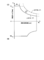
- FIG. 7 shows the swing rotational speed in the case of such a hybrid hydraulic shovel
- Fig. 6 shows a torque diagram showing the pivoting torques that can be taken for.
- a curved line LP1 is a maximum torque line that can be output by the turning electric motor, and is a maximum torque line when the P mode is set.
- Curve LE1 is the maximum torque line when the E mode is set. In such torque limitation, when the E mode is set, the maximum torque equal to or less than a predetermined number of revolutions is limited so as to be smaller than the maximum torque when the P mode is set.
- the output restriction of the swing electric motor at a swing speed other than the swing speed where there is a difference between the maximum torques in the P mode and the E mode is the same as in the P mode and the E mode.
- the mode is set, a difference occurs between the acceleration of the electric drive system and the acceleration of the hydraulic drive system, and there is a problem that the operator still feels an operational discomfort.
- the present invention has been made in view of the above, and it is an object of the present invention to provide a control device of an electric motor and a control method thereof which can reduce an operational discomfort including acceleration in a working machine. Do.
- a control device for an electric motor comprises an operation state setting unit for setting an operation state, and an electric motor preset according to the operation state set.
- Maximum output acquiring means for acquiring the maximum output
- rotational speed detecting means for detecting the rotational speed of the electric motor
- torque limit value calculating means for calculating the torque limit value based on the rotational speed and the maximum output
- a torque limiting unit configured to limit a torque of the electric motor according to the torque limit value at the time of acceleration of the electric motor.
- the torque limiting means is configured to set the torque limiting value for decelerating regardless of the operating state set at the time of decelerating the electric motor. It is characterized in that the torque of the electric motor is limited.
- the torque limiting means can output the maximum torque at a predetermined rotational speed or lower regardless of the set operating condition. I assume.
- the operation state setting means is a work mode selection unit and / or a throttle dial.
- an operation state setting step of setting an operation state a maximum output acquisition step of acquiring a maximum output of the electric motor preset by the operation state set, A torque limit value calculation step for calculating a torque limit value based on the rotation speed and the maximum output, and a torque limit value at the time of acceleration of the electric motor.
- a torque limiting step of limiting the torque of the electric motor a torque limiting step of limiting the torque of the electric motor.
- the torque limiting step may be performed by the torque limiting value for deceleration regardless of the operating state set at the time of deceleration of the electric motor. It is characterized in that the torque of the electric motor is limited.
- the torque limiting step can output the maximum torque at a predetermined rotational speed or lower regardless of the limitation of the torque limit value. I assume.
- the operation state setting step can output the maximum torque at a predetermined rotation speed or less regardless of the operation state set. It features.
- the maximum output of the electric motor preset according to the set operating condition is acquired, and the torque limit value is calculated based on the rotational speed of the electric motor and the acquired maximum output.
- FIG. 1 is a perspective view showing an entire configuration of a hybrid hydraulic shovel according to Embodiment 1 of the present invention.
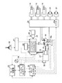
- FIG. 2 is a schematic view showing a configuration of a control system of the hybrid hydraulic shovel shown in FIG.
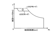
- FIG. 3 is a torque diagram showing an outline of torque limitation on the swing motor by the controller.
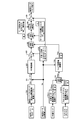
- FIG. 4 is a diagram showing a torque limit control flow for the swing motor by the controller.
- FIG. 5 is a diagram showing a torque restriction control flow for the electric motor by the controller according to the second embodiment of the present invention.
- FIG. 6 is a diagram showing a torque restriction control flow for the electric motor by the controller according to the third embodiment of the present invention.
- FIG. 7 is a torque diagram showing an example of torque limitation with respect to a conventional electric motor.
- FIG. 8 is a torque diagram showing another example of torque limitation with respect to a conventional electric motor.
- FIGS. 1 and 2 show the overall configuration of a hybrid hydraulic shovel 1 which is an example of a working machine.
- the hybrid hydraulic shovel 1 includes a vehicle body 2 and a working machine 3.
- the vehicle body 2 has a lower traveling body 4 and an upper revolving structure 5.
- the lower traveling body 4 has a pair of traveling devices 4a.
- Each traveling device 4a has a crawler belt 4b.
- Each traveling device 4a causes the hybrid hydraulic excavator 1 to travel by driving the crawler belt 4b by the right traveling motor and the left traveling motor (traveling motor 21).
- the upper swing body 5 is swingably provided on the lower traveling body 4 and swings when the swing motor 24 (electric motor) is driven. Further, in the upper swing body 5, a driver's cab 6 is provided.
- the upper revolving superstructure 5 has a fuel tank 7, a hydraulic oil tank 8, an engine chamber 9 and a counterweight 10.
- the fuel tank 7 stores fuel for driving the engine 17.
- the hydraulic oil tank 8 stores hydraulic oil discharged from the hydraulic pump 18 to hydraulic cylinders such as the boom cylinder 14 and hydraulic devices such as the traveling motor 21.
- the engine room 9 accommodates devices such as the engine 17 and the hydraulic pump 18.
- the counterweight 10 is disposed at the rear of the engine compartment 9.
- the work implement 3 is mounted at the front center position of the upper swing body 5 and has a boom 11, an arm 12, a bucket 13, a boom cylinder 14, an arm cylinder 15, and a bucket cylinder 16.
- the proximal end of the boom 11 is rotatably connected to the upper swing body 5.
- the distal end of the boom 11 is rotatably connected to the proximal end of the arm 12.
- the tip of the arm 12 is rotatably connected to the bucket 13.
- the boom cylinder 14, the arm cylinder 15, and the bucket cylinder 16 are hydraulic cylinders that perform expansion and contraction operations with hydraulic fluid discharged from a hydraulic pump.
- the boom cylinder 14 swings the boom 11.
- the arm cylinder 15 swings the arm 12.
- the bucket cylinder 16 swings the bucket 13.
- the hybrid hydraulic shovel 1 has an engine 17 as a drive source, a hydraulic pump 18, and a generator 19.
- a diesel engine is used as the engine 17, and a variable displacement hydraulic pump (for example, a swash plate hydraulic pump) is used as the hydraulic pump 18.
- a hydraulic pump 18 and a generator 19 are mechanically coupled to an output shaft of the engine 17, and driving the engine 17 drives the hydraulic pump 18 and the generator 19.
- the hydraulic drive system includes a control valve 20, a boom cylinder 14, an arm cylinder 15, a bucket cylinder 16, a traveling motor 21 and the like, and the hydraulic pump 18 serves as a hydraulic pressure source to drive them.
- the electric drive system includes a capacitor 22, an inverter 23, and a swing motor 24.
- the generator 19 and the capacitor 22 serve as a power source of the swing motor 24 to swing the upper swing body 5. That is, the swing motor 24 swings and accelerates the upper swing body 5 by performing a powering action with the electric energy supplied from the generator 19 or the capacitor 22, and the swing motor 24 regenerates when the upper swing body 5 swings and decelerates Supply (charge) the electrical energy to the capacitor 22.
- the generator 19 for example, an SR (switched reluctance) motor is used.
- the generator 19 is mechanically coupled to the output shaft of the engine 17, and the driving of the engine 17 causes the rotor shaft of the generator 19 to rotate.
- an electric double layer capacitor is used as the capacitor 22.
- the rotation motor 25 is provided with a rotation sensor 25.
- the rotation sensor 25 detects the rotation speed of the rotation motor 24, converts it into an electric signal, and outputs the electric signal to a hybrid controller 23a provided in the inverter 23.
- a hybrid controller 23a provided in the inverter 23.
- an embedded magnet synchronous motor is used as the swing motor 24.
- a resolver or a rotary encoder is used as the rotation sensor 25.
- the hybrid controller 23a is configured by a CPU (an arithmetic device such as a numerical operation processor), a memory (storage device), and the like.
- the hybrid controller 23a receives a signal of a detected value by a temperature sensor such as a thermistor or a thermocouple provided in the generator 19, the swing motor 24, the capacitor 22, and the inverter 23, and the temperature rise of each device such as the capacitor 22 And performs charge / discharge control of the capacitor 22, power generation / engine assist control by the generator 19, and power running / regeneration control of the swing motor 24.
- a temperature sensor such as a thermistor or a thermocouple provided in the generator 19
- the temperature rise of each device such as the capacitor 22
- the hydraulic drive system and the electric drive system are driven according to the operation of an operation lever 26 such as a work machine lever, a travel lever, or a turning lever provided in a driver's cab 6 provided in the vehicle main body 2.
- the operation amount of the operation lever 26 is converted into an electric signal by the lever operation amount detection unit 27.
- the lever operation amount detection unit 27 is configured by a pressure sensor. The pressure sensor detects a pilot hydraulic pressure generated according to the operation of the operation lever, and a lever operation amount is obtained by converting a voltage or the like output from the pressure sensor into a lever operation amount.
- the lever operation amount detection unit 27 is configured by an electrical detection unit such as a potentiometer, and converts a voltage or the like generated according to the lever operation amount into a lever operation amount. And calculate the lever operation amount.
- a fuel adjustment dial (throttle dial) 28 and a mode switching unit 29 are provided in the driver's cab 6, a fuel adjustment dial (throttle dial) 28 and a mode switching unit 29 are provided.
- the fuel adjustment dial (throttle dial) 28 is a switch for setting the amount of fuel supplied to the engine 17.
- the set value of the fuel adjustment dial (throttle dial) 28 is converted into an electric signal and output to the engine controller 30 Be done.
- the engine controller 30 is configured by an arithmetic device such as a CPU (numerical arithmetic processor) or a memory (storage device).
- the engine controller 30 generates a control command signal based on the set value of the fuel adjustment dial (throttle dial) 28, the common rail control unit 32 receives the control signal, and adjusts the fuel injection amount to the engine 17. That is, the engine 17 is an engine that can be electronically controlled by a common rail type, can appropriately output the target output by appropriately controlling the fuel injection amount, and can output the engine rotational speed at a certain moment It is possible to set the torque freely.
- the mode switching unit 29 is a part that sets the working mode of the hybrid hydraulic shovel 1 to the power mode (P mode) or the economy mode (E mode), and is, for example, an operation button or switch provided in the cab 6 or a touch panel.
- the operation mode can be switched by the operator of the hybrid hydraulic shovel 1 operating the operation buttons and the like.
- the power mode is a working mode in which engine control and pump control with reduced fuel consumption are performed while maintaining a large amount of work, and in the economy mode, the operating speed of the working machine 3 is secured by light load work while further reducing fuel consumption. It is an operation mode which performs engine control and pump control to do.
- the mode switching unit 29 When the setting (switching of the work mode) is performed by the mode switching unit 29, an electric signal according to the setting is output to the engine controller 30, the pump controller 33, and the hybrid controller 23a.
- the output torque of the engine 17 and the absorption torque of the hydraulic pump 18 are matched in a region where the engine output (rotation speed and output torque) of the engine 17 is relatively high. Also, in the economy mode, matching is performed with a lower engine output than in the power mode.
- the pump controller 33 receives the signals output from the engine controller 30, the mode switching unit 29, and the lever operation amount detection unit 27, controls the swash plate angle of the hydraulic pump 18, and discharges the hydraulic oil from the hydraulic pump 18 And generates a control command signal for adjusting the discharge amount of the ink.
- a signal from a swash plate angle sensor 18 a that detects a swash plate angle of the hydraulic pump 18 is input to the pump controller 33.
- the pump displacement of the hydraulic pump 18 can be calculated by the swash plate angle sensor 18a detecting the swash plate angle.
- a pump pressure detector 20a for detecting the pump discharge pressure of the hydraulic pump 18 is provided.
- the detected pump discharge pressure is converted into an electrical signal and input to the pump controller 33.
- the engine controller 30, the pump controller 33, and the hybrid controller 23a are connected by an in-vehicle LAN such as a CAN (Controller Area Network) so as to exchange information with each other.
- FIG. 3 shows an outline of torque limitation according to the first embodiment of the swing motor 24 by the engine controller 30, and is a torque diagram showing limit characteristics of the swing torque with respect to the number of revolutions.
- the turning torque at the time of power running is shown as positive, and the turning torque at the time of regeneration (deceleration) is shown as negative.
- torque limitation is performed with a torque limitation curve LP indicating the maximum torque that the swing motor 24 can output.
- the torque limitation curve LE which performs output limitation of the swing maximum output preset for the E mode. That is, when the work mode is set, torque limitation is performed with an equal horsepower curve corresponding to the maximum swing output for this work mode. Therefore, the fact that the swing maximum output for the working mode is reduced means that the equal horsepower curve of the swing motor 24 is a torque limit curve which is generally shifted to the lower left, as shown in FIG. As a result, it is possible to perform turning operation with acceleration corresponding to the hydraulic drive system, and there is no sense of discomfort in operation.
- torque limitation is performed with a torque limitation curve (LP or LE) corresponding to an equal horsepower curve, but in a region R1 where the number of revolutions of the turning motor 24 is low, the maximum torque TPmax is output to achieve turning operation.
- LP or LE torque limitation curve
- the torque that can be provided is small in the area where the number of revolutions is high, but in the area where the number of revolutions is high, even if the torque is low, the number of revolutions is high. Can get enough.
- FIG. 3 at the time of regeneration (deceleration), whichever operation mode is set, there is one torque limit curve, and there is no difference in torque limit. As a result, the stopping performance of the swing motor 24 can be sufficiently exhibited.
- the turning lever stroke is input to the turning lever stroke / turning target rotation speed conversion table TB1.
- the turning lever stroke / turning target rotation number conversion table TB1 calculates the turning target rotation number Sm corresponding to the inputted turning lever stroke based on the relationship between the turning lever stroke and the turning target rotation number set in advance. Output to the unit 101.
- the computing unit 101 subtracts the present swing motor rotation speed Sn detected by the rotation sensor 25 from the swing target rotation speed Sm, and inputs the subtracted rotation speed deviation ⁇ S to the PID control unit 102.
- the PID control unit 102 calculates the torque Ta from the rotational speed deviation ⁇ S.
- the torque Ta is multiplied by the gain K by the computing unit 103 and output to the minimum value selection unit (MIN selection) 106.
- the gain K is set to 1 by the positive / negative determination unit 104 if the number of revolutions of the rotation motor Sn is positive, and is set to -1 if the number is negative.
- a signal indicating the work mode set by the mode switching unit 29 is input to the work mode / maximum turning output conversion table TB11.
- the work mode / swing maximum output conversion table TB11 outputs, to the torque limit value calculation unit 105, the swing maximum output Plim set in advance for each work mode.
- the torque limit value calculator 105 calculates the torque limit value Tlim according to the following equation based on the input maximum swing output Plim and the absolute value of the swing motor rotation speed Sn.
- Tlim (Plim ⁇ 1000) / ((2 ⁇ / 60) ⁇ Sn)
- the calculated torque limit value Tlim is input to the minimum value selection unit 106.
- the minimum value selection unit 106 selects the smaller one of the torque (turning target torque) input from the computing unit 103 and the torque limit value Tlim input from the torque limit value calculation unit 105 and selects the minimum value selection unit (MIN selection ) Output.
- the minimum value selection unit 107 outputs, to the maximum value selection unit (MAX selection) 108, the smaller one of the torque input from the minimum value selection unit 106 and the motor powering maximum torque TPmax which is a preset fixed value. .
- the minimum value selection unit 107 acts to output a torque that does not have a larger value on the positive side than the motor powering maximum torque TPmax in the case of the powering, particularly in the region R1 where the number of revolutions is low.
- Maximum value selection unit 108 selects and outputs the larger one of the torque input from minimum value selection unit 107 and motor regeneration maximum torque TMmax (negative value), which is a preset fixed value. Since maximum torque TMmax during motor regeneration is a negative value, maximum value selecting section 108 selects the torque input from minimum value selecting section 107 as the maximum value during power running, but it is determined by computing element 103 during regeneration. Since a negative value torque is output, the maximum value selection unit 108 outputs a torque that does not become smaller than the motor regeneration maximum torque TMmax in comparison with the motor regeneration maximum torque TMmax. It will be. That is, according to the swing lever stroke, the swing motor torque command Tc is output in the limited range of the motor regeneration maximum torque TMmax (lower limit of the swing torque).
- the torque limit value Tlim obtained by the torque limit value calculation unit 105 is a positive value
- the gain K from the positive / negative determination unit 104 Since the torque Ta given as 1 and output from the PID control unit 102 has a negative value, as a result, the minimum value selecting unit 106 selects the torque Ta having the negative value. Therefore, at the time of regeneration (deceleration), the swing motor command value Tc is determined and output regardless of the operation mode.
- the computing unit 109 multiplies the torque output from the maximum value selecting unit 108 by a gain K which is a value corresponding to the positive or negative of the swing motor rotation speed Sn, and turns the torque Tc which is the multiplied value It outputs to the hybrid controller 23a as a motor torque command.
- torque limitation like a torque diagram shown in FIG. 3 can be performed.
- the hybrid controller 23a may perform the processing for obtaining the swing motor torque command described above instead of the engine controller 30, or the controller combining the engine controller 30 and the hybrid controller 23a may perform the swing motor torque command You may make it process which calculates
- the turning maximum output Plim is determined by the work mode, and the torque limit value Tlim is calculated using the turning maximum output Plim.
- the working mode is changed to The turning maximum output Plim is obtained from the setting value of the throttle dial (fuel adjustment dial 28), and the torque limit value Tlim is calculated using this turning maximum output Plim.
- engine output control can also be performed by the throttle dial to set the operating state.
- FIG. 5 shows a torque limit control flow according to the second embodiment.
- the signal according to the setting value of the throttle dial (fuel adjustment dial 28) is used instead of the signal according to the operation mode of FIG. , Throttle dial, maximum turning output conversion table TB12 is used.
- the other configuration is the same as in FIG.
- FIG. 6 shows a torque limit control flow according to the third embodiment of the present invention.
- torque limit control combining the first embodiment and the second embodiment is performed. That is, a signal corresponding to the operation mode and a signal corresponding to the setting value of the throttle dial (fuel adjustment dial 28) are input, and the respective signals are the operation mode / maximum turning output conversion table TB11, the throttle dial, The maximum turning output conversion table TB12 is input, and the turning maximum outputs Plima and Plimb are converted and output. Then, the minimum value selection unit (MIN selection) 201 inputs the swing maximum output Plim, which is the minimum value among them, into the torque limit value calculation unit 105.
- MIN selection minimum value selection unit
- Embodiment 4 instead of the signal according to the work mode of the first embodiment, a signal according to a work pattern is input.
- a signal corresponding to the work pattern is input as a signal indicating one of the plurality of work patterns determined by performing the work pattern determination process. Then, when a signal indicating the work pattern is input, the work pattern / swing maximum output conversion table converts the work into the swing maximum output Plim set in advance for each work pattern and outputs it.
- the arm lever for moving the arm 12 of the work machine lever 26 is operated in the digging direction and the pump discharge pressure of the hydraulic pump 18 is also higher than a certain set value
- the determination process of the work pattern is to estimate the work that the operator is to perform at that time based on the specific input value.
- the hoist turning operation is an operation of turning the upper swing body 5 while raising the boom 11 up and removing earth and sand excavated by the bucket 13 and removing earth and sand of the bucket 13 at a desired turning stop position.
- the hydraulic fluid temperature is used as an input, and the value of the swing maximum output Plim output from each table is converted and corrected according to the hydraulic fluid temperature by the hydraulic fluid temperature and maximum swing output conversion table. It is also good.
- the hydraulic oil temperature is low and the viscosity of the hydraulic oil is increased.
- An increase in the viscosity of the hydraulic fluid causes a decrease in the operating speed of the working machine, but since the swing motor 24 operates independently of the temperature of the hydraulic fluid because of electric drive, it operates in the operation of the upper swing body 5 by the swing motor 24 If the oil temperature is not taken into consideration, the operator feels uncomfortable.
- the swing operation can be performed in harmony with the operation speed of work implement 3.
- the swing maximum output decreases with the decrease of the hydraulic fluid temperature because the hydraulic motor makes a swing. Therefore, the operator does not feel a sense of incongruity when performing control in which the information of the hydraulic oil temperature is taken, as in the present embodiment.
- the hybrid hydraulic shovel 1 has a sensor for detecting the temperature of the hydraulic fluid of the hydraulic pump 18, and the engine controller 30, the pump controller 33 or the hybrid controller 23a monitors the temperature of the hydraulic fluid.
- the output balance between the work of the electric drive system by the swing motor 24 and the work of the hydraulic drive system can be further balanced and torque balanced, and the work operation The above discomfort can be reduced.
Landscapes
- Engineering & Computer Science (AREA)
- Mining & Mineral Resources (AREA)
- Civil Engineering (AREA)
- General Engineering & Computer Science (AREA)
- Structural Engineering (AREA)
- Power Engineering (AREA)
- Operation Control Of Excavators (AREA)
- Control Of Electric Motors In General (AREA)
Abstract
Description
[全体構成]
まず、図1および図2は、作業機械としての一例であるハイブリッド油圧ショベル1の全体構成を示している。このハイブリッド油圧ショベル1は、車両本体2と作業機3とを備えている。車両本体2は、下部走行体4と上部旋回体5とを有する。下部走行体4は、一対の走行装置4aを有する。各走行装置4aは、履帯4bを有する。各走行装置4aは、右走行モータと左走行モータ(走行モータ21)とによって履帯4bを駆動させることによってハイブリッド油圧ショベル1を走行させる。
つぎに、旋回モータ24に対するトルク制限の概要について説明する。図3は、エンジンコントローラ30による旋回モータ24に対する本実施の形態1によるトルク制限の概要を示すものであり、旋回回転数に対する旋回トルクの制限特性を示すトルク線図である。図3において、力行(加速)時の旋回トルクは正で示し、回生(減速)時の旋回トルクは負で示している。モード切替部29によってPモードが設定されると、旋回モータ24が出力可能な最大のトルクを示すトルク制限曲線LPでトルク制限される。一方、モード切替部29によってEモードが設定されると、このEモードに対して予め設定された旋回最大出力の出力制限を行うトルク制限曲線LEで力行(加速)時のトルク制限を行う。すなわち、作業モードの設定がなされると、この作業モードに対する旋回最大出力に対応する等馬力曲線でトルク制限を行う。したがって、作業モードに対する旋回最大出力が小さくなるということは、旋回モータ24の等馬力曲線は、図3に示すように、全体的に左下に移行したトルク制限曲線となる。この結果、油圧駆動系に対応した加速性をもった旋回作業が可能となり、作業操作上の違和感がなくなる。
つぎに、図4を参照して、旋回モータ24に対する具体的なトルク制限制御について説明する。図4において、まず、エンジンコントローラ30には、操作レバー26による旋回レバーストローク(操作レバー26の操作量)と、回転センサ25によって検出される旋回モータ24の旋回モータ回転数と、モード切替部29によって設定された作業モードを示す電気信号とが、直接あるいはハイブリッドコントローラ23aを介して入力される。
Tlim=(Plim×1000)/((2π/60)×Sn)
この演算されたトルク制限値Tlimは、最小値選択部106に入力される。
上述した実施の形態1では、作業モードによって旋回最大出力Plimを求め、この旋回最大出力Plimを用いてトルク制限値Tlimを演算するようにしていたが、この実施の形態2では、作業モードに替えて、スロットルダイヤル(燃料調整ダイヤル28)の設定値によって旋回最大出力Plimを求め、この旋回最大出力Plimを用いてトルク制限値Tlimを演算するようにしている。ハイブリッド油圧ショベル1では、スロットルダイヤルによってもエンジン出力制御を行い、稼動状態を設定することができるからである。
図6は、この発明の実施の形態3によるトルク制限制御フローを示している。この実施の形態3では、実施の形態1と実施の形態2とを組み合わせたトルク制限制御を行うようにしている。すなわち、作業モードに応じた信号とスロットルダイヤル(燃料調整ダイヤル28)の設定値に応じた信号とを入力される信号とし、それぞれの信号は、作業モード・旋回最大出力変換テーブルTB11、スロットルダイヤル・旋回最大出力変換テーブルTB12に入力され、それぞれ旋回最大出力Plima,Plimbを変換出力する。そして、最小値選択部(MIN選択)201は、これらのうちの最小値である旋回最大出力Plimをトルク制限値演算部105に入力する。その他の構成は、図4,5と同じである。
この実施の形態4では、実施の形態1の作業モードに応じた信号に替えて作業パターンに応じた信号を入力するようにしている。この作業パターンに応じた信号は、作業パターンの判定処理を行うことによって判定された、複数の作業パターンのうちの1つの作業パターンが作業パターンを示す信号として入力される。そして、この作業パターンを示す信号が入力されると、作業パターン・旋回最大出力変換テーブルによって、作業パターン毎に予め設定された旋回最大出力Plimに変換して出力する。
この実施の形態5では、作動油温度を入力とし、作動油温度・旋回最大出力変換テーブルによって各テーブルから出力された旋回最大出力Plimの値を、作動油温度に応じて補正変換するようにしてもよい。外気温度が低い環境やハイブリッド油圧ショベル1の始動時などでは、作動油温度が低く、作動油の粘性が上がる。作動油の粘性の上昇は、作業機の動作速度の低下を招くが、旋回モータ24は電気駆動のため作動油の温度に関係なく動作するため、旋回モータ24による上部旋回体5の動作に作動油の温度を考慮しなければオペレータは違和感を感じる。したがって、この実施の形態5のように旋回最大出力Plimの値を、作動油温度に応じて補正変換すれば、作業機3の動作速度に調和した旋回動作を行うことができる。なお、ハイブリッド油圧ショベルではない通常の油圧ショベルでは、油圧モータで旋回するため、旋回最大出力は、作動油温度の低下に伴って減少する。したがって、本実施の形態のような作動油温度の情報を取り入れた制御を行うと、オペレータは違和感を感じない。なお、ハイブリッド油圧ショベル1は、油圧ポンプ18の作動油温度を検出するセンサを有し、エンジンコントローラ30、ポンプコントローラ33あるいはハイブリッドコントローラ23aは、作動油温度をモニタする。
2 車両本体
3 作業機
4 下部走行体
5 上部旋回体
11 ブーム
12 アーム
13 バケット
14 ブームシリンダ
15 アームシリンダ
16 バケットシリンダ
17 エンジン
18 油圧ポンプ
18a 斜板角センサ
19 発電機
20 コントロールバルブ
20a ポンプ圧検出部
21 走行モータ
22 キャパシタ
23 インバータ
23a ハイブリッドコントローラ
24 旋回モータ
25 回転センサ
26 操作レバー
27 レバー操作量検出部
28 燃料調整ダイヤル
29 モード切替部
30 エンジンコントローラ
32 コモンレール制御部
33 ポンプコントローラ
105 トルク制限値演算部
Claims (8)
- 稼働状態を設定する稼働状態設定手段と、
設定される前記稼働状態によって予め設定される電動モータの最大出力を取得する最大出力取得手段と、
電動モータの回転速度を検出する回転速度検出手段と、
前記回転速度と前記最大出力とをもとにトルク制限値を演算するトルク制限値演算手段と、
前記電動モータの加速時に、前記トルク制限値によって前記電動モータのトルクを制限するトルク制限手段と、
を備えたことを特徴とする電動モータの制御装置。 - 前記トルク制限手段は、前記電動モータの減速時に、設定される前記稼動状態にかかわらず、減速のためのトルク制限値で前記電動モータのトルクを制限することを特徴とする請求項1に記載の電動モータの制御装置。
- 前記トルク制限手段は、所定回転速度以下では、設定される前記稼働状態にかかわらず、最大トルクを出力可能にすることを特徴とする請求項1または2に記載の電動モータの制御装置。
- 前記稼働状態設定手段は、作業モード選択部および/またはスロットルダイヤルであることを特徴とする請求項1~3のいずれか一つに記載の電動モータの制御装置。
- 稼働状態を設定する稼働状態設定ステップと、
設定される前記稼働状態によって予め設定される電動モータの最大出力を取得する最大出力取得ステップと、
電動モータの回転速度を検出する回転速度検出ステップと、
前記回転速度と前記最大出力とをもとにトルク制限値を演算するトルク制限値演算ステップと、
前記電動モータの加速時に、前記トルク制限値によって前記電動モータのトルクを制限するトルク制限ステップと、
を含むことを特徴とする電動モータの制御方法。 - 前記トルク制限ステップは、前記電動モータの減速時に、設定される前記稼動状態にかかわらず、減速のためのトルク制限値で前記電動モータのトルクを制限することを特徴とする請求項5に記載の電動モータの制御方法。
- 前記トルク制限ステップは、所定回転速度以下では、設定される前記稼動状態にかかわらず、最大トルクを出力可能にすることを特徴とする請求項5または6に記載の電動モータの制御方法。
- 前記稼働状態設定ステップは、作業モード選択設定および/またはスロットルダイヤル値の設定であることを特徴とする請求項5~7のいずれか一つに記載の電動モータの制御方法。
Priority Applications (4)
| Application Number | Priority Date | Filing Date | Title |
|---|---|---|---|
| KR1020137004600A KR101521361B1 (ko) | 2011-05-18 | 2012-04-16 | 전동 모터의 제어 장치 및 그 제어 방법 |
| US13/814,790 US9654038B2 (en) | 2011-05-18 | 2012-04-16 | Control device and method for controlling electric motor |
| DE112012000073T DE112012000073T5 (de) | 2011-05-18 | 2012-04-16 | Steuerungsvorrichtung und Verfahren zur Steuerung eines Elektromotors |
| CN201280002510.1A CN103081350B (zh) | 2011-05-18 | 2012-04-16 | 电动机的控制装置及其控制方法 |
Applications Claiming Priority (2)
| Application Number | Priority Date | Filing Date | Title |
|---|---|---|---|
| JP2011111390A JP5193333B2 (ja) | 2011-05-18 | 2011-05-18 | 電動モータの制御装置およびその制御方法 |
| JP2011-111390 | 2011-05-18 |
Publications (1)
| Publication Number | Publication Date |
|---|---|
| WO2012157382A1 true WO2012157382A1 (ja) | 2012-11-22 |
Family
ID=47176722
Family Applications (1)
| Application Number | Title | Priority Date | Filing Date |
|---|---|---|---|
| PCT/JP2012/060260 Ceased WO2012157382A1 (ja) | 2011-05-18 | 2012-04-16 | 電動モータの制御装置およびその制御方法 |
Country Status (6)
| Country | Link |
|---|---|
| US (1) | US9654038B2 (ja) |
| JP (1) | JP5193333B2 (ja) |
| KR (1) | KR101521361B1 (ja) |
| CN (1) | CN103081350B (ja) |
| DE (1) | DE112012000073T5 (ja) |
| WO (1) | WO2012157382A1 (ja) |
Families Citing this family (11)
| Publication number | Priority date | Publication date | Assignee | Title |
|---|---|---|---|---|
| US9206587B2 (en) * | 2012-03-16 | 2015-12-08 | Harnischfeger Technologies, Inc. | Automated control of dipper swing for a shovel |
| US9567730B2 (en) | 2013-08-30 | 2017-02-14 | Hitachi Construction Machinery Co., Ltd. | Work machine |
| JP6162613B2 (ja) * | 2014-01-17 | 2017-07-12 | 住友建機株式会社 | 道路舗装機械 |
| CN104727364A (zh) * | 2015-03-25 | 2015-06-24 | 国机重工(洛阳)有限公司 | 一种永磁同步交流电动机驱动的推土机的速度自微调装置 |
| KR102471489B1 (ko) * | 2015-07-15 | 2022-11-28 | 현대두산인프라코어(주) | 건설기계 및 건설기계의 제어 방법 |
| JP6510728B2 (ja) * | 2016-09-15 | 2019-05-08 | 日立建機株式会社 | ダンプトラックのピッチング制御システム |
| JP2019193445A (ja) * | 2018-04-25 | 2019-10-31 | 日本電産株式会社 | モータ駆動装置 |
| JP2020043665A (ja) * | 2018-09-10 | 2020-03-19 | Ntn株式会社 | 電動式アクチュエータおよび電動ブレーキ装置 |
| EP4033124A4 (en) * | 2019-09-18 | 2023-08-23 | Kubota Corporation | CONSTRUCTION MACHINE |
| US12024860B2 (en) * | 2021-02-18 | 2024-07-02 | Deere & Company | Preheating intelligence for electric-hydraulic work vehicles |
| JP7491858B2 (ja) * | 2021-02-22 | 2024-05-28 | 株式会社小松製作所 | 作業機モーメントを推定する方法 |
Citations (6)
| Publication number | Priority date | Publication date | Assignee | Title |
|---|---|---|---|---|
| JP2001011897A (ja) * | 1999-06-30 | 2001-01-16 | Kobe Steel Ltd | 建設機械の旋回駆動装置 |
| JP2003155760A (ja) * | 2001-11-21 | 2003-05-30 | Kobelco Contstruction Machinery Ltd | 作業機械のアクチュエータ駆動装置 |
| JP2008088659A (ja) * | 2006-09-29 | 2008-04-17 | Kobelco Contstruction Machinery Ltd | 作業機械の旋回制御装置 |
| JP2008115640A (ja) * | 2006-11-07 | 2008-05-22 | Shin Caterpillar Mitsubishi Ltd | 作業機械における旋回制御装置 |
| JP2009127295A (ja) * | 2007-11-22 | 2009-06-11 | Sumitomo (Shi) Construction Machinery Manufacturing Co Ltd | 旋回駆動制御装置及びこれを含む建設機械 |
| JP2010106511A (ja) * | 2008-10-29 | 2010-05-13 | Kobelco Contstruction Machinery Ltd | 作業機械の旋回制御装置 |
Family Cites Families (9)
| Publication number | Priority date | Publication date | Assignee | Title |
|---|---|---|---|---|
| JPS61230917A (ja) * | 1985-04-08 | 1986-10-15 | Fanuc Ltd | 射出成形機の射出圧制御方式 |
| KR910009257B1 (ko) * | 1985-09-07 | 1991-11-07 | 히다찌 겡끼 가부시기가이샤 | 유압건설기계의 제어시스템 |
| JP3694573B2 (ja) * | 1997-03-10 | 2005-09-14 | ファナック株式会社 | プレス機械におけるモータトルク制御方法及びプレス機械 |
| FI113309B (fi) * | 2001-06-29 | 2004-03-31 | Abb Oy | Verkkokatkoshidastus |
| DE112004001742B4 (de) | 2004-06-11 | 2014-05-28 | Mitsubishi Denki K.K. | Motorsteuerverfahren und vorrichtung zur durchführung des verfahrens |
| EP1813728A4 (en) * | 2004-11-17 | 2014-09-17 | Komatsu Mfg Co Ltd | SWIVEL CONTROL DEVICE AND CONSTRUCTION MACHINE |
| JP4188902B2 (ja) * | 2004-11-22 | 2008-12-03 | 日立建機株式会社 | 油圧建設機械の制御装置 |
| US8374755B2 (en) * | 2007-07-31 | 2013-02-12 | Caterpillar Inc. | Machine with task-dependent control |
| JP2009068197A (ja) | 2007-09-11 | 2009-04-02 | Kobelco Contstruction Machinery Ltd | 電動旋回式作業機械の旋回制御装置 |
-
2011
- 2011-05-18 JP JP2011111390A patent/JP5193333B2/ja not_active Expired - Fee Related
-
2012
- 2012-04-16 WO PCT/JP2012/060260 patent/WO2012157382A1/ja not_active Ceased
- 2012-04-16 DE DE112012000073T patent/DE112012000073T5/de not_active Withdrawn
- 2012-04-16 CN CN201280002510.1A patent/CN103081350B/zh not_active Expired - Fee Related
- 2012-04-16 US US13/814,790 patent/US9654038B2/en not_active Expired - Fee Related
- 2012-04-16 KR KR1020137004600A patent/KR101521361B1/ko not_active Expired - Fee Related
Patent Citations (6)
| Publication number | Priority date | Publication date | Assignee | Title |
|---|---|---|---|---|
| JP2001011897A (ja) * | 1999-06-30 | 2001-01-16 | Kobe Steel Ltd | 建設機械の旋回駆動装置 |
| JP2003155760A (ja) * | 2001-11-21 | 2003-05-30 | Kobelco Contstruction Machinery Ltd | 作業機械のアクチュエータ駆動装置 |
| JP2008088659A (ja) * | 2006-09-29 | 2008-04-17 | Kobelco Contstruction Machinery Ltd | 作業機械の旋回制御装置 |
| JP2008115640A (ja) * | 2006-11-07 | 2008-05-22 | Shin Caterpillar Mitsubishi Ltd | 作業機械における旋回制御装置 |
| JP2009127295A (ja) * | 2007-11-22 | 2009-06-11 | Sumitomo (Shi) Construction Machinery Manufacturing Co Ltd | 旋回駆動制御装置及びこれを含む建設機械 |
| JP2010106511A (ja) * | 2008-10-29 | 2010-05-13 | Kobelco Contstruction Machinery Ltd | 作業機械の旋回制御装置 |
Also Published As
| Publication number | Publication date |
|---|---|
| US9654038B2 (en) | 2017-05-16 |
| US20140084831A1 (en) | 2014-03-27 |
| JP2012244730A (ja) | 2012-12-10 |
| KR101521361B1 (ko) | 2015-05-18 |
| KR20130057464A (ko) | 2013-05-31 |
| CN103081350A (zh) | 2013-05-01 |
| CN103081350B (zh) | 2015-08-05 |
| JP5193333B2 (ja) | 2013-05-08 |
| DE112012000073T5 (de) | 2013-05-29 |
Similar Documents
| Publication | Publication Date | Title |
|---|---|---|
| JP5193333B2 (ja) | 電動モータの制御装置およびその制御方法 | |
| US9347389B2 (en) | Engine control device of work machine and engine control method therefor | |
| JP5244214B2 (ja) | 作業機械のエンジン制御装置およびそのエンジン制御方法 | |
| JP5667830B2 (ja) | 旋回体を有する建設機械 | |
| KR101652661B1 (ko) | 건설 기계 | |
| JP5356427B2 (ja) | ハイブリッド式建設機械 | |
| KR101671876B1 (ko) | 선회제어장치 및 방법 | |
| JP5665874B2 (ja) | ハイブリッド型作業機械及びその制御方法 | |
| KR101714948B1 (ko) | 건설 기계 | |
| JP5969437B2 (ja) | 建設機械 | |
| KR101897830B1 (ko) | 하이브리드식 건설 기계 | |
| WO2013058325A1 (ja) | ハイブリッド駆動式の油圧作業機械 | |
| KR101549117B1 (ko) | 하이브리드식 작업기계 및 그 제어방법 | |
| JP6072303B2 (ja) | 建設機械 | |
| JP5364080B2 (ja) | 電動機の制御装置、電動機の制御方法、及び電動機の制御装置を備えた建設機械 | |
| JP2008115640A (ja) | 作業機械における旋回制御装置 | |
| JP5946594B2 (ja) | 作業車両及びその制御方法 | |
| JP5723947B2 (ja) | 旋回体を有する建設機械 | |
| WO2020039862A1 (ja) | ハイブリッド建設機械 | |
| WO2020044921A1 (ja) | ハイブリッド建設機械 |
Legal Events
| Date | Code | Title | Description |
|---|---|---|---|
| WWE | Wipo information: entry into national phase |
Ref document number: 201280002510.1 Country of ref document: CN |
|
| 121 | Ep: the epo has been informed by wipo that ep was designated in this application |
Ref document number: 12785851 Country of ref document: EP Kind code of ref document: A1 |
|
| WWE | Wipo information: entry into national phase |
Ref document number: 13814790 Country of ref document: US |
|
| WWE | Wipo information: entry into national phase |
Ref document number: 112012000073 Country of ref document: DE Ref document number: 1120120000730 Country of ref document: DE |
|
| ENP | Entry into the national phase |
Ref document number: 20137004600 Country of ref document: KR Kind code of ref document: A |
|
| 122 | Ep: pct application non-entry in european phase |
Ref document number: 12785851 Country of ref document: EP Kind code of ref document: A1 |