WO2012157300A1 - 複合積層セラミック電子部品 - Google Patents
複合積層セラミック電子部品 Download PDFInfo
- Publication number
- WO2012157300A1 WO2012157300A1 PCT/JP2012/053260 JP2012053260W WO2012157300A1 WO 2012157300 A1 WO2012157300 A1 WO 2012157300A1 JP 2012053260 W JP2012053260 W JP 2012053260W WO 2012157300 A1 WO2012157300 A1 WO 2012157300A1
- Authority
- WO
- WIPO (PCT)
- Prior art keywords
- dielectric constant
- ceramic
- weight
- glass
- ceramic layer
- Prior art date
- Legal status (The legal status is an assumption and is not a legal conclusion. Google has not performed a legal analysis and makes no representation as to the accuracy of the status listed.)
- Ceased
Links
Images


Classifications
-
- B—PERFORMING OPERATIONS; TRANSPORTING
- B32—LAYERED PRODUCTS
- B32B—LAYERED PRODUCTS, i.e. PRODUCTS BUILT-UP OF STRATA OF FLAT OR NON-FLAT, e.g. CELLULAR OR HONEYCOMB, FORM
- B32B7/00—Layered products characterised by the relation between layers; Layered products characterised by the relative orientation of features between layers, or by the relative values of a measurable parameter between layers, i.e. products comprising layers having different physical, chemical or physicochemical properties; Layered products characterised by the interconnection of layers
- B32B7/02—Physical, chemical or physicochemical properties
- B32B7/025—Electric or magnetic properties
-
- B—PERFORMING OPERATIONS; TRANSPORTING
- B32—LAYERED PRODUCTS
- B32B—LAYERED PRODUCTS, i.e. PRODUCTS BUILT-UP OF STRATA OF FLAT OR NON-FLAT, e.g. CELLULAR OR HONEYCOMB, FORM
- B32B18/00—Layered products essentially comprising ceramics, e.g. refractory products
-
- C—CHEMISTRY; METALLURGY
- C03—GLASS; MINERAL OR SLAG WOOL
- C03C—CHEMICAL COMPOSITION OF GLASSES, GLAZES OR VITREOUS ENAMELS; SURFACE TREATMENT OF GLASS; SURFACE TREATMENT OF FIBRES OR FILAMENTS MADE FROM GLASS, MINERALS OR SLAGS; JOINING GLASS TO GLASS OR OTHER MATERIALS
- C03C3/00—Glass compositions
- C03C3/04—Glass compositions containing silica
- C03C3/062—Glass compositions containing silica with less than 40% silica by weight
- C03C3/064—Glass compositions containing silica with less than 40% silica by weight containing boron
-
- C—CHEMISTRY; METALLURGY
- C03—GLASS; MINERAL OR SLAG WOOL
- C03C—CHEMICAL COMPOSITION OF GLASSES, GLAZES OR VITREOUS ENAMELS; SURFACE TREATMENT OF GLASS; SURFACE TREATMENT OF FIBRES OR FILAMENTS MADE FROM GLASS, MINERALS OR SLAGS; JOINING GLASS TO GLASS OR OTHER MATERIALS
- C03C8/00—Enamels; Glazes; Fusion seal compositions being frit compositions having non-frit additions
- C03C8/02—Frit compositions, i.e. in a powdered or comminuted form
-
- C—CHEMISTRY; METALLURGY
- C03—GLASS; MINERAL OR SLAG WOOL
- C03C—CHEMICAL COMPOSITION OF GLASSES, GLAZES OR VITREOUS ENAMELS; SURFACE TREATMENT OF GLASS; SURFACE TREATMENT OF FIBRES OR FILAMENTS MADE FROM GLASS, MINERALS OR SLAGS; JOINING GLASS TO GLASS OR OTHER MATERIALS
- C03C8/00—Enamels; Glazes; Fusion seal compositions being frit compositions having non-frit additions
- C03C8/14—Glass frit mixtures having non-frit additions, e.g. opacifiers, colorants, mill-additions
-
- C—CHEMISTRY; METALLURGY
- C03—GLASS; MINERAL OR SLAG WOOL
- C03C—CHEMICAL COMPOSITION OF GLASSES, GLAZES OR VITREOUS ENAMELS; SURFACE TREATMENT OF GLASS; SURFACE TREATMENT OF FIBRES OR FILAMENTS MADE FROM GLASS, MINERALS OR SLAGS; JOINING GLASS TO GLASS OR OTHER MATERIALS
- C03C8/00—Enamels; Glazes; Fusion seal compositions being frit compositions having non-frit additions
- C03C8/14—Glass frit mixtures having non-frit additions, e.g. opacifiers, colorants, mill-additions
- C03C8/20—Glass frit mixtures having non-frit additions, e.g. opacifiers, colorants, mill-additions containing titanium compounds; containing zirconium compounds
-
- C—CHEMISTRY; METALLURGY
- C04—CEMENTS; CONCRETE; ARTIFICIAL STONE; CERAMICS; REFRACTORIES
- C04B—LIME, MAGNESIA; SLAG; CEMENTS; COMPOSITIONS THEREOF, e.g. MORTARS, CONCRETE OR LIKE BUILDING MATERIALS; ARTIFICIAL STONE; CERAMICS; REFRACTORIES; TREATMENT OF NATURAL STONE
- C04B35/00—Shaped ceramic products characterised by their composition; Ceramics compositions; Processing powders of inorganic compounds preparatory to the manufacturing of ceramic products
- C04B35/01—Shaped ceramic products characterised by their composition; Ceramics compositions; Processing powders of inorganic compounds preparatory to the manufacturing of ceramic products based on oxide ceramics
- C04B35/16—Shaped ceramic products characterised by their composition; Ceramics compositions; Processing powders of inorganic compounds preparatory to the manufacturing of ceramic products based on oxide ceramics based on silicates other than clay
- C04B35/20—Shaped ceramic products characterised by their composition; Ceramics compositions; Processing powders of inorganic compounds preparatory to the manufacturing of ceramic products based on oxide ceramics based on silicates other than clay rich in magnesium oxide, e.g. forsterite
-
- C—CHEMISTRY; METALLURGY
- C04—CEMENTS; CONCRETE; ARTIFICIAL STONE; CERAMICS; REFRACTORIES
- C04B—LIME, MAGNESIA; SLAG; CEMENTS; COMPOSITIONS THEREOF, e.g. MORTARS, CONCRETE OR LIKE BUILDING MATERIALS; ARTIFICIAL STONE; CERAMICS; REFRACTORIES; TREATMENT OF NATURAL STONE
- C04B35/00—Shaped ceramic products characterised by their composition; Ceramics compositions; Processing powders of inorganic compounds preparatory to the manufacturing of ceramic products
- C04B35/01—Shaped ceramic products characterised by their composition; Ceramics compositions; Processing powders of inorganic compounds preparatory to the manufacturing of ceramic products based on oxide ceramics
- C04B35/44—Shaped ceramic products characterised by their composition; Ceramics compositions; Processing powders of inorganic compounds preparatory to the manufacturing of ceramic products based on oxide ceramics based on aluminates
- C04B35/443—Magnesium aluminate spinel
-
- H—ELECTRICITY
- H01—ELECTRIC ELEMENTS
- H01G—CAPACITORS; CAPACITORS, RECTIFIERS, DETECTORS, SWITCHING DEVICES, LIGHT-SENSITIVE OR TEMPERATURE-SENSITIVE DEVICES OF THE ELECTROLYTIC TYPE
- H01G4/00—Fixed capacitors; Processes of their manufacture
- H01G4/002—Details
- H01G4/018—Dielectrics
- H01G4/06—Solid dielectrics
- H01G4/08—Inorganic dielectrics
- H01G4/12—Ceramic dielectrics
- H01G4/129—Ceramic dielectrics containing a glassy phase, e.g. glass ceramic
-
- H—ELECTRICITY
- H01—ELECTRIC ELEMENTS
- H01G—CAPACITORS; CAPACITORS, RECTIFIERS, DETECTORS, SWITCHING DEVICES, LIGHT-SENSITIVE OR TEMPERATURE-SENSITIVE DEVICES OF THE ELECTROLYTIC TYPE
- H01G4/00—Fixed capacitors; Processes of their manufacture
- H01G4/30—Stacked capacitors
-
- C—CHEMISTRY; METALLURGY
- C04—CEMENTS; CONCRETE; ARTIFICIAL STONE; CERAMICS; REFRACTORIES
- C04B—LIME, MAGNESIA; SLAG; CEMENTS; COMPOSITIONS THEREOF, e.g. MORTARS, CONCRETE OR LIKE BUILDING MATERIALS; ARTIFICIAL STONE; CERAMICS; REFRACTORIES; TREATMENT OF NATURAL STONE
- C04B2235/00—Aspects relating to ceramic starting mixtures or sintered ceramic products
- C04B2235/02—Composition of constituents of the starting material or of secondary phases of the final product
- C04B2235/30—Constituents and secondary phases not being of a fibrous nature
- C04B2235/32—Metal oxides, mixed metal oxides, or oxide-forming salts thereof, e.g. carbonates, nitrates, (oxy)hydroxides, chlorides
- C04B2235/3205—Alkaline earth oxides or oxide forming salts thereof, e.g. beryllium oxide
- C04B2235/3206—Magnesium oxides or oxide-forming salts thereof
-
- C—CHEMISTRY; METALLURGY
- C04—CEMENTS; CONCRETE; ARTIFICIAL STONE; CERAMICS; REFRACTORIES
- C04B—LIME, MAGNESIA; SLAG; CEMENTS; COMPOSITIONS THEREOF, e.g. MORTARS, CONCRETE OR LIKE BUILDING MATERIALS; ARTIFICIAL STONE; CERAMICS; REFRACTORIES; TREATMENT OF NATURAL STONE
- C04B2235/00—Aspects relating to ceramic starting mixtures or sintered ceramic products
- C04B2235/02—Composition of constituents of the starting material or of secondary phases of the final product
- C04B2235/30—Constituents and secondary phases not being of a fibrous nature
- C04B2235/32—Metal oxides, mixed metal oxides, or oxide-forming salts thereof, e.g. carbonates, nitrates, (oxy)hydroxides, chlorides
- C04B2235/3205—Alkaline earth oxides or oxide forming salts thereof, e.g. beryllium oxide
- C04B2235/3215—Barium oxides or oxide-forming salts thereof
-
- C—CHEMISTRY; METALLURGY
- C04—CEMENTS; CONCRETE; ARTIFICIAL STONE; CERAMICS; REFRACTORIES
- C04B—LIME, MAGNESIA; SLAG; CEMENTS; COMPOSITIONS THEREOF, e.g. MORTARS, CONCRETE OR LIKE BUILDING MATERIALS; ARTIFICIAL STONE; CERAMICS; REFRACTORIES; TREATMENT OF NATURAL STONE
- C04B2235/00—Aspects relating to ceramic starting mixtures or sintered ceramic products
- C04B2235/02—Composition of constituents of the starting material or of secondary phases of the final product
- C04B2235/30—Constituents and secondary phases not being of a fibrous nature
- C04B2235/32—Metal oxides, mixed metal oxides, or oxide-forming salts thereof, e.g. carbonates, nitrates, (oxy)hydroxides, chlorides
- C04B2235/3217—Aluminum oxide or oxide forming salts thereof, e.g. bauxite, alpha-alumina
-
- C—CHEMISTRY; METALLURGY
- C04—CEMENTS; CONCRETE; ARTIFICIAL STONE; CERAMICS; REFRACTORIES
- C04B—LIME, MAGNESIA; SLAG; CEMENTS; COMPOSITIONS THEREOF, e.g. MORTARS, CONCRETE OR LIKE BUILDING MATERIALS; ARTIFICIAL STONE; CERAMICS; REFRACTORIES; TREATMENT OF NATURAL STONE
- C04B2235/00—Aspects relating to ceramic starting mixtures or sintered ceramic products
- C04B2235/02—Composition of constituents of the starting material or of secondary phases of the final product
- C04B2235/30—Constituents and secondary phases not being of a fibrous nature
- C04B2235/32—Metal oxides, mixed metal oxides, or oxide-forming salts thereof, e.g. carbonates, nitrates, (oxy)hydroxides, chlorides
- C04B2235/3217—Aluminum oxide or oxide forming salts thereof, e.g. bauxite, alpha-alumina
- C04B2235/3222—Aluminates other than alumino-silicates, e.g. spinel (MgAl2O4)
-
- C—CHEMISTRY; METALLURGY
- C04—CEMENTS; CONCRETE; ARTIFICIAL STONE; CERAMICS; REFRACTORIES
- C04B—LIME, MAGNESIA; SLAG; CEMENTS; COMPOSITIONS THEREOF, e.g. MORTARS, CONCRETE OR LIKE BUILDING MATERIALS; ARTIFICIAL STONE; CERAMICS; REFRACTORIES; TREATMENT OF NATURAL STONE
- C04B2235/00—Aspects relating to ceramic starting mixtures or sintered ceramic products
- C04B2235/02—Composition of constituents of the starting material or of secondary phases of the final product
- C04B2235/30—Constituents and secondary phases not being of a fibrous nature
- C04B2235/32—Metal oxides, mixed metal oxides, or oxide-forming salts thereof, e.g. carbonates, nitrates, (oxy)hydroxides, chlorides
- C04B2235/3224—Rare earth oxide or oxide forming salts thereof, e.g. scandium oxide
-
- C—CHEMISTRY; METALLURGY
- C04—CEMENTS; CONCRETE; ARTIFICIAL STONE; CERAMICS; REFRACTORIES
- C04B—LIME, MAGNESIA; SLAG; CEMENTS; COMPOSITIONS THEREOF, e.g. MORTARS, CONCRETE OR LIKE BUILDING MATERIALS; ARTIFICIAL STONE; CERAMICS; REFRACTORIES; TREATMENT OF NATURAL STONE
- C04B2235/00—Aspects relating to ceramic starting mixtures or sintered ceramic products
- C04B2235/02—Composition of constituents of the starting material or of secondary phases of the final product
- C04B2235/30—Constituents and secondary phases not being of a fibrous nature
- C04B2235/32—Metal oxides, mixed metal oxides, or oxide-forming salts thereof, e.g. carbonates, nitrates, (oxy)hydroxides, chlorides
- C04B2235/3231—Refractory metal oxides, their mixed metal oxides, or oxide-forming salts thereof
- C04B2235/3232—Titanium oxides or titanates, e.g. rutile or anatase
-
- C—CHEMISTRY; METALLURGY
- C04—CEMENTS; CONCRETE; ARTIFICIAL STONE; CERAMICS; REFRACTORIES
- C04B—LIME, MAGNESIA; SLAG; CEMENTS; COMPOSITIONS THEREOF, e.g. MORTARS, CONCRETE OR LIKE BUILDING MATERIALS; ARTIFICIAL STONE; CERAMICS; REFRACTORIES; TREATMENT OF NATURAL STONE
- C04B2235/00—Aspects relating to ceramic starting mixtures or sintered ceramic products
- C04B2235/02—Composition of constituents of the starting material or of secondary phases of the final product
- C04B2235/30—Constituents and secondary phases not being of a fibrous nature
- C04B2235/32—Metal oxides, mixed metal oxides, or oxide-forming salts thereof, e.g. carbonates, nitrates, (oxy)hydroxides, chlorides
- C04B2235/3262—Manganese oxides, manganates, rhenium oxides or oxide-forming salts thereof, e.g. MnO
-
- C—CHEMISTRY; METALLURGY
- C04—CEMENTS; CONCRETE; ARTIFICIAL STONE; CERAMICS; REFRACTORIES
- C04B—LIME, MAGNESIA; SLAG; CEMENTS; COMPOSITIONS THEREOF, e.g. MORTARS, CONCRETE OR LIKE BUILDING MATERIALS; ARTIFICIAL STONE; CERAMICS; REFRACTORIES; TREATMENT OF NATURAL STONE
- C04B2235/00—Aspects relating to ceramic starting mixtures or sintered ceramic products
- C04B2235/02—Composition of constituents of the starting material or of secondary phases of the final product
- C04B2235/30—Constituents and secondary phases not being of a fibrous nature
- C04B2235/32—Metal oxides, mixed metal oxides, or oxide-forming salts thereof, e.g. carbonates, nitrates, (oxy)hydroxides, chlorides
- C04B2235/3281—Copper oxides, cuprates or oxide-forming salts thereof, e.g. CuO or Cu2O
-
- C—CHEMISTRY; METALLURGY
- C04—CEMENTS; CONCRETE; ARTIFICIAL STONE; CERAMICS; REFRACTORIES
- C04B—LIME, MAGNESIA; SLAG; CEMENTS; COMPOSITIONS THEREOF, e.g. MORTARS, CONCRETE OR LIKE BUILDING MATERIALS; ARTIFICIAL STONE; CERAMICS; REFRACTORIES; TREATMENT OF NATURAL STONE
- C04B2235/00—Aspects relating to ceramic starting mixtures or sintered ceramic products
- C04B2235/02—Composition of constituents of the starting material or of secondary phases of the final product
- C04B2235/30—Constituents and secondary phases not being of a fibrous nature
- C04B2235/34—Non-metal oxides, non-metal mixed oxides, or salts thereof that form the non-metal oxides upon heating, e.g. carbonates, nitrates, (oxy)hydroxides, chlorides
- C04B2235/3418—Silicon oxide, silicic acids or oxide forming salts thereof, e.g. silica sol, fused silica, silica fume, cristobalite, quartz or flint
-
- C—CHEMISTRY; METALLURGY
- C04—CEMENTS; CONCRETE; ARTIFICIAL STONE; CERAMICS; REFRACTORIES
- C04B—LIME, MAGNESIA; SLAG; CEMENTS; COMPOSITIONS THEREOF, e.g. MORTARS, CONCRETE OR LIKE BUILDING MATERIALS; ARTIFICIAL STONE; CERAMICS; REFRACTORIES; TREATMENT OF NATURAL STONE
- C04B2235/00—Aspects relating to ceramic starting mixtures or sintered ceramic products
- C04B2235/02—Composition of constituents of the starting material or of secondary phases of the final product
- C04B2235/30—Constituents and secondary phases not being of a fibrous nature
- C04B2235/34—Non-metal oxides, non-metal mixed oxides, or salts thereof that form the non-metal oxides upon heating, e.g. carbonates, nitrates, (oxy)hydroxides, chlorides
- C04B2235/3427—Silicates other than clay, e.g. water glass
- C04B2235/3436—Alkaline earth metal silicates, e.g. barium silicate
- C04B2235/3445—Magnesium silicates, e.g. forsterite
-
- C—CHEMISTRY; METALLURGY
- C04—CEMENTS; CONCRETE; ARTIFICIAL STONE; CERAMICS; REFRACTORIES
- C04B—LIME, MAGNESIA; SLAG; CEMENTS; COMPOSITIONS THEREOF, e.g. MORTARS, CONCRETE OR LIKE BUILDING MATERIALS; ARTIFICIAL STONE; CERAMICS; REFRACTORIES; TREATMENT OF NATURAL STONE
- C04B2235/00—Aspects relating to ceramic starting mixtures or sintered ceramic products
- C04B2235/02—Composition of constituents of the starting material or of secondary phases of the final product
- C04B2235/30—Constituents and secondary phases not being of a fibrous nature
- C04B2235/34—Non-metal oxides, non-metal mixed oxides, or salts thereof that form the non-metal oxides upon heating, e.g. carbonates, nitrates, (oxy)hydroxides, chlorides
- C04B2235/3427—Silicates other than clay, e.g. water glass
- C04B2235/3463—Alumino-silicates other than clay, e.g. mullite
- C04B2235/3481—Alkaline earth metal alumino-silicates other than clay, e.g. cordierite, beryl, micas such as margarite, plagioclase feldspars such as anorthite, zeolites such as chabazite
-
- C—CHEMISTRY; METALLURGY
- C04—CEMENTS; CONCRETE; ARTIFICIAL STONE; CERAMICS; REFRACTORIES
- C04B—LIME, MAGNESIA; SLAG; CEMENTS; COMPOSITIONS THEREOF, e.g. MORTARS, CONCRETE OR LIKE BUILDING MATERIALS; ARTIFICIAL STONE; CERAMICS; REFRACTORIES; TREATMENT OF NATURAL STONE
- C04B2235/00—Aspects relating to ceramic starting mixtures or sintered ceramic products
- C04B2235/02—Composition of constituents of the starting material or of secondary phases of the final product
- C04B2235/30—Constituents and secondary phases not being of a fibrous nature
- C04B2235/36—Glass starting materials for making ceramics, e.g. silica glass
-
- C—CHEMISTRY; METALLURGY
- C04—CEMENTS; CONCRETE; ARTIFICIAL STONE; CERAMICS; REFRACTORIES
- C04B—LIME, MAGNESIA; SLAG; CEMENTS; COMPOSITIONS THEREOF, e.g. MORTARS, CONCRETE OR LIKE BUILDING MATERIALS; ARTIFICIAL STONE; CERAMICS; REFRACTORIES; TREATMENT OF NATURAL STONE
- C04B2235/00—Aspects relating to ceramic starting mixtures or sintered ceramic products
- C04B2235/02—Composition of constituents of the starting material or of secondary phases of the final product
- C04B2235/30—Constituents and secondary phases not being of a fibrous nature
- C04B2235/36—Glass starting materials for making ceramics, e.g. silica glass
- C04B2235/365—Borosilicate glass
-
- C—CHEMISTRY; METALLURGY
- C04—CEMENTS; CONCRETE; ARTIFICIAL STONE; CERAMICS; REFRACTORIES
- C04B—LIME, MAGNESIA; SLAG; CEMENTS; COMPOSITIONS THEREOF, e.g. MORTARS, CONCRETE OR LIKE BUILDING MATERIALS; ARTIFICIAL STONE; CERAMICS; REFRACTORIES; TREATMENT OF NATURAL STONE
- C04B2235/00—Aspects relating to ceramic starting mixtures or sintered ceramic products
- C04B2235/60—Aspects relating to the preparation, properties or mechanical treatment of green bodies or pre-forms
- C04B2235/602—Making the green bodies or pre-forms by moulding
- C04B2235/6025—Tape casting, e.g. with a doctor blade
-
- C—CHEMISTRY; METALLURGY
- C04—CEMENTS; CONCRETE; ARTIFICIAL STONE; CERAMICS; REFRACTORIES
- C04B—LIME, MAGNESIA; SLAG; CEMENTS; COMPOSITIONS THEREOF, e.g. MORTARS, CONCRETE OR LIKE BUILDING MATERIALS; ARTIFICIAL STONE; CERAMICS; REFRACTORIES; TREATMENT OF NATURAL STONE
- C04B2235/00—Aspects relating to ceramic starting mixtures or sintered ceramic products
- C04B2235/70—Aspects relating to sintered or melt-casted ceramic products
- C04B2235/80—Phases present in the sintered or melt-cast ceramic products other than the main phase
-
- C—CHEMISTRY; METALLURGY
- C04—CEMENTS; CONCRETE; ARTIFICIAL STONE; CERAMICS; REFRACTORIES
- C04B—LIME, MAGNESIA; SLAG; CEMENTS; COMPOSITIONS THEREOF, e.g. MORTARS, CONCRETE OR LIKE BUILDING MATERIALS; ARTIFICIAL STONE; CERAMICS; REFRACTORIES; TREATMENT OF NATURAL STONE
- C04B2237/00—Aspects relating to ceramic laminates or to joining of ceramic articles with other articles by heating
- C04B2237/30—Composition of layers of ceramic laminates or of ceramic or metallic articles to be joined by heating, e.g. Si substrates
- C04B2237/32—Ceramic
- C04B2237/34—Oxidic
- C04B2237/341—Silica or silicates
-
- C—CHEMISTRY; METALLURGY
- C04—CEMENTS; CONCRETE; ARTIFICIAL STONE; CERAMICS; REFRACTORIES
- C04B—LIME, MAGNESIA; SLAG; CEMENTS; COMPOSITIONS THEREOF, e.g. MORTARS, CONCRETE OR LIKE BUILDING MATERIALS; ARTIFICIAL STONE; CERAMICS; REFRACTORIES; TREATMENT OF NATURAL STONE
- C04B2237/00—Aspects relating to ceramic laminates or to joining of ceramic articles with other articles by heating
- C04B2237/30—Composition of layers of ceramic laminates or of ceramic or metallic articles to be joined by heating, e.g. Si substrates
- C04B2237/32—Ceramic
- C04B2237/34—Oxidic
- C04B2237/343—Alumina or aluminates
-
- C—CHEMISTRY; METALLURGY
- C04—CEMENTS; CONCRETE; ARTIFICIAL STONE; CERAMICS; REFRACTORIES
- C04B—LIME, MAGNESIA; SLAG; CEMENTS; COMPOSITIONS THEREOF, e.g. MORTARS, CONCRETE OR LIKE BUILDING MATERIALS; ARTIFICIAL STONE; CERAMICS; REFRACTORIES; TREATMENT OF NATURAL STONE
- C04B2237/00—Aspects relating to ceramic laminates or to joining of ceramic articles with other articles by heating
- C04B2237/50—Processing aspects relating to ceramic laminates or to the joining of ceramic articles with other articles by heating
- C04B2237/62—Forming laminates or joined articles comprising holes, channels or other types of openings
-
- C—CHEMISTRY; METALLURGY
- C04—CEMENTS; CONCRETE; ARTIFICIAL STONE; CERAMICS; REFRACTORIES
- C04B—LIME, MAGNESIA; SLAG; CEMENTS; COMPOSITIONS THEREOF, e.g. MORTARS, CONCRETE OR LIKE BUILDING MATERIALS; ARTIFICIAL STONE; CERAMICS; REFRACTORIES; TREATMENT OF NATURAL STONE
- C04B2237/00—Aspects relating to ceramic laminates or to joining of ceramic articles with other articles by heating
- C04B2237/50—Processing aspects relating to ceramic laminates or to the joining of ceramic articles with other articles by heating
- C04B2237/66—Forming laminates or joined articles showing high dimensional accuracy, e.g. indicated by the warpage
-
- Y—GENERAL TAGGING OF NEW TECHNOLOGICAL DEVELOPMENTS; GENERAL TAGGING OF CROSS-SECTIONAL TECHNOLOGIES SPANNING OVER SEVERAL SECTIONS OF THE IPC; TECHNICAL SUBJECTS COVERED BY FORMER USPC CROSS-REFERENCE ART COLLECTIONS [XRACs] AND DIGESTS
- Y10—TECHNICAL SUBJECTS COVERED BY FORMER USPC
- Y10T—TECHNICAL SUBJECTS COVERED BY FORMER US CLASSIFICATION
- Y10T428/00—Stock material or miscellaneous articles
- Y10T428/24—Structurally defined web or sheet [e.g., overall dimension, etc.]
- Y10T428/24942—Structurally defined web or sheet [e.g., overall dimension, etc.] including components having same physical characteristic in differing degree
Definitions
- the present invention relates to a multilayer ceramic electronic component such as a multilayer ceramic substrate in which, for example, a microwave resonator, a filter or a capacitor is formed, and in particular, a low dielectric constant ceramic layer having a relatively low dielectric constant and
- the present invention relates to a composite multilayer ceramic electronic component having a composite structure in which a high dielectric constant ceramic layer having a relatively high dielectric constant is laminated.
- Patent Document 1 and Patent Document 2 also describe a glass ceramic composition suitable for forming a low dielectric constant ceramic layer or a glass ceramic composition suitable for forming a high dielectric constant ceramic layer. Yes.
- Patent Document 1 describes a glass ceramic composition containing MgAl 2 O 4 -based ceramic and glass in claim 1. More specifically, MgAl 2 O 4 ceramic powder, silicon oxide 13 to 50% by weight in terms of SiO 2 , boron oxide 8 to 60% by weight in terms of B 2 O 3 , and aluminum oxide in terms of Al 2 O 3 And a glass powder containing 10 to 55% by weight of magnesium oxide in terms of MgO.
- Patent Document 1 describes that in claim 2, it may further contain an alkaline earth metal oxide in a proportion of 20% by weight or less.
- the glass content is 20% of the total. It is described that the content is preferably ⁇ 80% by weight.
- a relatively low relative dielectric constant can be obtained in the sintered body such that the relative dielectric constant is, for example, 8 or less, and it is suitable for high frequency applications. Can do.
- Patent Document 2 BaO—TiO 2 —RE 2 O 3 (RE is a rare earth element) -based dielectric and glass as a high dielectric constant material constituting a high dielectric constant ceramic layer having a relatively high relative dielectric constant.
- the glass is 10 to 25 wt% SiO 2 , 10 to 40 wt% B 2 O 3 , 25 to 55 wt% MgO, and 0 to 20 wt%.
- the glass content is preferably 15 to 35% by weight.
- Patent Document 2 describes a material similar to Patent Document 1.
- the glass contained in the glass-ceramic composition described in each of Patent Documents 1 and 2 is for enabling firing at a temperature of 1000 ° C. or less, but has a composition that is easily crystallized.
- the glass component and the ceramic component react with each other during the firing process to precipitate crystals, so that the amount of crystals and the amount of glass components at the time of firing completion are stabilized. It is difficult to do. And it is estimated that the instability of the amount of crystals and the amount of the glass component at the time of completion of baking lowers the insulation reliability.
- the glass contained in the glass ceramic compositions described in Patent Documents 1 and 2 contains a relatively large amount of MgO.
- the glass component causes MgAl 2 O 4 and / or or believed crystal Mg 2 SiO 4 is deposited, this is estimated that led to decrease in insulation reliability.
- the high dielectric constant material described in Patent Document 2 requires the addition of glass in order to enable firing at a temperature of 1000 ° C. or lower.
- BaO—TiO it is necessary to include a 2- RE 2 O 3 based dielectric.
- Ti ions released from the BaO—TiO 2 —RE 2 O 3 dielectric material cause oxygen defects. Such oxygen vacancies can cause a decrease in insulation reliability, particularly under high temperature, high voltage, and long time use.
- each glass ceramic composition described in Patent Documents 1 and 2 has a desired dielectric constant in a wide range from low to high relative dielectric constant. It has come to recognize the problem that it is difficult to obtain things stably.
- the glass contained in the glass ceramic composition described in Patent Documents 1 and 2 is easily crystallized by reacting with the ceramic component in the firing process as described above. If crystals are deposited, the relative permittivity changes, and it is difficult to obtain a desired relative permittivity.
- the glass contained in the glass ceramic compositions described in Patent Documents 1 and 2 does not have good wettability with respect to MgAl 2 O 4 ceramics or BaO—TiO 2 —RE 2 O 3 dielectrics. Therefore, the glass ceramic composition cannot be sintered unless a relatively large amount of glass is added. However, when the amount of glass added is large, the relative dielectric constant is lowered. For this reason, it is particularly difficult to produce a high dielectric constant material.
- the characteristics obtained with a low dielectric constant ceramic layer alone and the characteristics obtained with a high dielectric constant ceramic layer alone are: It must also be taken into account whether it is almost maintained in the case of co-firing with layers.
- the glass contained in the glass ceramic composition described in each of Patent Documents 1 and 2 has a composition that easily crystallizes, it is possible to stabilize the amount of crystals and the amount of glass components at the completion of firing. From the point of difficulty, it is speculated that there is a possibility that the individual characteristics of each ceramic layer may be lost as a result of co-firing of the low dielectric constant ceramic layer and the high dielectric constant ceramic layer. .
- an object of the present invention is that the low dielectric constant ceramic layer and the high dielectric constant ceramic layer can be co-fired, and corresponding characteristics can be obtained in each of the low dielectric constant ceramic layer and the high dielectric constant ceramic layer. It is to provide a composite multilayer ceramic electronic component.
- the present invention is directed to a composite multilayer ceramic electronic component including a laminated low dielectric constant ceramic layer and a high dielectric constant ceramic layer, and has the following configuration in order to solve the technical problem described above. It is characterized by having.
- the low dielectric constant ceramic layer and the high dielectric constant ceramic layer are both (1) a first ceramic made of at least one of MgAl 2 O 4 and Mg 2 SiO 4 , and (2) BaO, RE 2 O 3 ( RE is a rare earth element) and a second ceramic composed of TiO 2 , and (3) RO (R is at least one alkaline earth metal selected from Ba, Ca and Sr) is 44.0 to 69.0% by weight.
- SiO 2 is 14.2 to 30.0 wt%
- B 2 O 3 is 10.0 to 20.0 wt%
- Al 2 O 3 is 0.5 to 4.0 wt%
- Li 2 O is 0.2 wt%. 3 to 7.5% by weight and glass containing 0.1 to 5.5% by weight of MgO and (4) MnO.
- the low dielectric constant ceramic layer includes 47.55 to 69.32% by weight of the first ceramic, 6 to 20% by weight of the glass, 7.5 to 18.5% by weight of MnO,
- the second ceramic contains 0.38 to 1.43% by weight of BaO, 1.33 to 9.5% by weight of RE 2 O 3 and 0.95 to 6.75% by weight of TiO 2 , respectively.
- the relative dielectric constant is 15 or less.
- the high dielectric constant ceramic layer includes 1 to 15% by weight of the first ceramic, 3 to 15% by weight of the glass, 2.3 to 10% by weight of MnO, and serves as the second ceramic.
- the glass content GL contained in the low dielectric constant ceramic layer and the glass content GH contained in the high dielectric constant ceramic layer satisfy the condition of 1.0 ⁇ G L / G H ⁇ 2.0. To be filled. As can be seen from the experimental examples described later, if this condition is satisfied, the insulation reliability of the low dielectric constant ceramic layer can be improved.
- the content M H of MnO contained in the content M L and the high dielectric constant ceramic layer of MnO contained in the low dielectric constant ceramic layer is of 1.5 ⁇ M L / M H ⁇ 3.6 To meet the requirements. As can be seen from the experimental examples described later, if this condition is satisfied, the insulation reliability of the high dielectric constant ceramic layer can be improved.
- both of the above two conditions are satisfied.
- the insulation reliability of both the low dielectric constant ceramic layer and the high dielectric constant ceramic layer can be further improved.
- the low dielectric constant ceramic layer preferably further contains 3.0 to 20.0% by weight of at least one of Mg 2 Al 4 Si 5 O 18 and BaAl 2 Si 2 O 8 .
- the low dielectric constant ceramic layer may further contain 0.23% by weight or less of CuO, and the high dielectric constant ceramic layer may further contain 1.2% by weight or less of CuO.
- the low dielectric constant ceramic layer and the high dielectric constant ceramic layer are made of a glass ceramic containing a common element, the low dielectric constant ceramic layer and the high dielectric constant ceramic layer can be co-sintered without any problem. it can.
- the glass contained therein is difficult to crystallize, and since MnO is contained, the insulation reliability can be increased.
- the specific dielectric constant is 15 or less, the insulation reliability is high, the Qf value is high, and the capacitance temperature coefficient (TCC) is 150 ppm / K or less in absolute value. Can be obtained.
- the specific dielectric constant is 30 or more, the insulation reliability is high, the Qf value is high, and the capacitance temperature coefficient (TCC) is 150 ppm / K or less in absolute value. Can be obtained.
- FIG. 4 is an equivalent circuit diagram given by the LC filter 21 shown in FIG. 3. It is a perspective view which decomposes
- a ceramic multilayer module 1 including a multilayer ceramic substrate 2 as an example of a composite multilayer ceramic electronic component according to the present invention will be described.
- the multilayer ceramic substrate 2 included in the ceramic multilayer module 1 includes a plurality of stacked low dielectric constant ceramic layers 3 and a plurality of stacked high dielectric constant ceramic layers 4, and the plurality of low dielectric constant ceramic layers 3 includes a plurality of low dielectric constant ceramic layers 3. They are positioned so as to sandwich the high dielectric constant ceramic layer 4, and these are co-fired.
- the low dielectric constant ceramic layer 3 and the high dielectric constant ceramic layer 4 are both (1) a first ceramic composed of at least one of MgAl 2 O 4 and Mg 2 SiO 4 ; (2) a second ceramic composed of BaO, RE 2 O 3 (RE is a rare earth element) and TiO 2 ; (3) RO (R is at least one alkaline earth metal selected from Ba, Ca and Sr) 44.0 to 69.0% by weight, SiO 2 14.2 to 30.0% by weight, B 2 10.0-30.0% by weight of O 3 , 0.5-4.0% by weight of Al 2 O 3 , 0.3-7.5% by weight of Li 2 O, and 0.1-5% of MgO Glass containing 5 wt% each; (4) It consists of a glass ceramic containing MnO.
- the low dielectric constant ceramic layer 3 and the high dielectric constant ceramic layer 4 are made of a glass ceramic containing a common element, the low dielectric constant ceramic layer 3 and the high dielectric constant ceramic layer 4 are co-sintered without any problem. be able to.
- the glass contained in this glass ceramic has a composition that is difficult to crystallize. Therefore, the amount of crystals and the amount of glass components at the time of completion of firing are stabilized, so that the insulation reliability can be improved. Since this glass has a lower MgO content than the glass contained in those described in Patent Documents 1 and 2, precipitation of crystals such as MgAl 2 O 4 and Mg 2 SiO 4 can be suppressed, and RO It is because it can be set as the composition which does not crystallize by increasing content.
- the glass ceramic composition contains MnO.
- the thing of patent document 1 and 2 does not contain MnO.
- Ti ions generated by the reduction of the Ti oxide cause oxygen defects and can cause a decrease in insulation reliability under high temperature, high voltage, and long-time use.
- the occurrence of oxygen defects due to substitution of Mn by Ti sites is suppressed. This is also presumed to contribute to the improvement of insulation reliability.
- the glasses described in Patent Documents 1 and 2 are easily crystallized by reacting with a ceramic component, and therefore the relative permittivity is likely to change.
- the glass contained in the glass ceramic used in the present invention is difficult to crystallize, it is easy to produce a product having a desired dielectric constant.
- the glass contained in the glass ceramic used in the present invention is a glass having high wettability and low reactivity with respect to the first ceramic and the second ceramic. Therefore, the glass ceramic can be sintered even if the glass component is reduced, and conversely, even if the glass component is increased, it is difficult to react and is stable. Therefore, in glass ceramics, it is possible to adjust the content of each of the ceramic component and the glass component widely. Therefore, by adjusting the content of each of the ceramic component and the glass component, the low dielectric constant product to the high dielectric constant can be adjusted. A wide range of products can be easily provided. That is, as described below, a glass ceramic suitable for constituting the low dielectric constant ceramic layer 3 and a glass ceramic suitable for constituting the high dielectric constant ceramic layer 4 can be provided.
- composition of the glass ceramic used in the present invention does not vary greatly before and after firing.
- B 2 O 3 and Li 2 O in the glass may volatilize during firing, but even in that case, the ratio of other components after firing is almost the same as that before firing.
- the glass ceramic constituting the low dielectric constant ceramic layer 3 contains 47.55 to 69.32% by weight of the first ceramic, 6 to 20% by weight of glass, and 7.5 to 18.5% by weight of MnO.
- the second ceramic contains 0.38 to 1.43% by weight of BaO, 1.33 to 9.5% by weight of RE 2 O 3 , and 0.95 to 6.75% by weight of TiO 2 , respectively. Yes.
- the low dielectric constant ceramic layer 3 has characteristics such that the relative dielectric constant is 15 or less, the insulation reliability is high, the Qf value is high, and the capacitance temperature coefficient (TCC) is 150 ppm / K or less in absolute value. Obtainable.
- the glass ceramic constituting the high dielectric constant ceramic layer 4 contains 1 to 15% by weight of the first ceramic, 3 to 15% by weight of glass, 2.3 to 10% by weight of MnO,
- BaO is contained in an amount of 2.5 to 15.7% by weight
- RE 2 O 3 in an amount of 24.6 to 65.3% by weight
- TiO 2 in an amount of 11.2 to 36.4% by weight.
- the high dielectric constant ceramic layer 4 has characteristics such that the relative dielectric constant is 30 or more, the insulation reliability is high, the Qf value is high, and the capacitance temperature coefficient (TCC) is 150 ppm / K or less in absolute value. Obtainable.
- the glass content GL contained in the low dielectric constant ceramic layer 3 and the glass content GH contained in the high dielectric constant ceramic layer 4 satisfy 1.0 ⁇ G L / G H ⁇ 2.0. To meet the requirements. As can be seen from the experimental examples described later, if this condition is satisfied, the insulation reliability of the low dielectric constant ceramic layer 3 can be improved. This is presumably because the mutual diffusion between the glass component of the low dielectric constant ceramic layer 3 and the glass component of the high dielectric constant ceramic layer 4 can be suppressed.
- Condition 6 is satisfied. As can be seen from the experimental examples described later, if this condition is satisfied, the insulation reliability of the high dielectric constant ceramic layer 4 can be improved. This is presumed to be because mutual diffusion between the MnO component of the low dielectric constant ceramic layer 3 and the MnO component of the high dielectric constant ceramic layer 4 can be suppressed.
- both of the above two conditions are satisfied.
- the insulation reliability of both the low dielectric constant ceramic layer 3 and the high dielectric constant ceramic layer 4 can be further improved.
- the low dielectric constant ceramic layer 3 preferably further contains 3.0 to 20.0 wt% of at least one of Mg 2 Al 4 Si 5 O 18 and BaAl 2 Si 2 O 8 .
- the multilayer ceramic substrate 2 can be made less likely to warp.
- the low dielectric constant ceramic layer 3 may further contain 0.23% by weight or less of CuO, and the high dielectric constant ceramic layer 4 may further contain 1.2% by weight or less of CuO.
- the multilayer ceramic substrate 2 includes various wiring conductors.
- As the wiring conductor typically, an internal conductor film 6 formed along a specific interface between the ceramic layers 3 and 4, a via-hole conductor 7 extending so as to penetrate a specific one of the ceramic layers 3 and 4, There is an external conductor film 8 formed on the outer surface of the multilayer ceramic substrate 2.
- a plurality of electronic components 9 to 17 are mounted on the upper surface of the multilayer ceramic substrate 2.
- the electronic component 9 is a diode
- the electronic component 11 is a multilayer ceramic capacitor
- the electronic component 16 is a semiconductor IC.
- These electronic components 9 to 17 are connected to a specific one of the outer conductor films 8 formed on the upper surface of the multilayer ceramic substrate 2 and, together with the wiring conductors formed inside the multilayer ceramic substrate 2, the ceramic multilayer A circuit necessary for the module 1 is configured.
- a conductive cap 18 for shielding the electronic components 9 to 17 is fixed on the upper surface of the multilayer ceramic substrate 2.
- the conductive cap 18 is electrically connected to a specific one of the via hole conductors 7 described above.
- the ceramic multilayer module 1 is mounted on a mother board (not shown) using a specific one of the external conductor films 8 formed on the lower surface of the multilayer ceramic substrate 2 as a connection terminal.
- the multilayer ceramic substrate 2 can be manufactured using a well-known ceramic laminated integrated firing technique.
- a ceramic green sheet for the low dielectric constant ceramic layer 3 is produced. More specifically, an organic vehicle composed of a binder resin and a solvent is added to the raw material composition that gives the glass ceramic described above to obtain a ceramic slurry. This ceramic slurry is formed into a sheet by, for example, a doctor blade method, dried, and then punched to a predetermined size to obtain a ceramic green sheet. And in order to form a wiring conductor in this ceramic green sheet, the conductive paste which has copper or silver as a main component, for example is provided with a desired pattern.
- the ceramic green sheet containing the raw material composition that gives the glass ceramic constituting the high dielectric constant ceramic layer 4 is produced in the same manner as the ceramic green sheet for the low dielectric constant ceramic layer 3.
- the conductive paste which has copper or silver as a main component, for example is provided with a desired pattern.
- the ceramic green sheet for the low dielectric constant ceramic layer 3 and the ceramic green sheet for the high dielectric constant ceramic layer 4 obtained as described above are laminated in a predetermined order, respectively. Next, pressure is applied in the thickness direction.
- the multilayer ceramic substrate 2 can be obtained by firing the raw laminated body obtained as described above at a temperature of 1000 ° C. or lower, for example, 800 to 1000 ° C.
- the firing is performed in a non-oxidizing atmosphere such as a nitrogen atmosphere when the wiring conductor is mainly composed of copper, and is performed in an oxidizing atmosphere such as the air when the wiring conductor is mainly composed of silver.
- the electronic components 9 to 17 are mounted, and the conductive cap 18 is attached, whereby the ceramic multilayer module 1 is completed.
- the relative dielectric constant in the low dielectric constant ceramic layer 3 provided in the multilayer ceramic substrate 2, the relative dielectric constant is 15 or less, the Qf value is high, and the capacitance temperature coefficient is 150 ppm in absolute value.
- the relative dielectric constant in the high dielectric constant ceramic layer 4, the relative dielectric constant is 30 or more, the Qf value is high, and the capacitance temperature coefficient (TCC) is 150 ppm / K or less in absolute value. It can be suitable for high frequency applications and excellent in reliability. Moreover, the insulation reliability of the ceramic multilayer module 1 can be made excellent.
- the LC filter 21 includes a component main body 23 as a laminated structure including a plurality of laminated glass ceramic layers. On the outer surface of the component main body 23, each end portion Are provided with terminal electrodes 24 and 25, and terminal electrodes 26 and 27 are provided at intermediate portions of the respective side surfaces.
- the LC filter 21 includes two inductances L1 and L2 connected in series between the terminal electrodes 24 and 25, and between the connection point of the inductances L1 and L2 and the terminal electrodes 26 and 27.
- a capacitance C is formed.
- the component main body 23 includes a plurality of laminated ceramic layers 28 to 40.
- the number of laminated ceramic layers is not limited to that shown in the figure.
- an organic vehicle composed of a binder resin and a solvent is added to a raw material composition that gives glass ceramic, and a ceramic slurry obtained by mixing these is formed into a sheet by a doctor blade method. Then, after drying, the ceramic green sheet obtained by punching out to a predetermined size is fired.
- a wiring conductor is provided in the following manner in relation to a specific one of the ceramic layers 28 to 40.
- the ceramic layer 30 is formed with a coil pattern 41 constituting a part of the inductance L1 and a lead pattern 42 extending from one end of the coil pattern 41.
- a via hole conductor is formed at the other end of the coil pattern 41. 43 is provided.
- the lead pattern 42 is connected to the terminal electrode 24.
- the ceramic layer 31 is provided with a coil pattern 44 constituting a part of the inductance L1, and a via-hole conductor 45 is provided at one end thereof. The other end of the coil pattern 44 is connected to the via hole conductor 43 described above.
- the ceramic layer 32 is provided with a via-hole conductor 46 connected to the above-described via-hole conductor 45.
- a capacitor pattern 47 constituting a part of the capacitance C is formed, and lead patterns 48 and 49 extending from the capacitor pattern 47 are formed.
- the lead patterns 48 and 49 are connected to the terminal electrodes 26 and 27.
- the ceramic layer 33 is provided with a via-hole conductor 50 connected to the aforementioned via-hole conductor 46.
- the ceramic layer 34 is provided with a capacitor pattern 51 constituting a part of the capacitance C and a via-hole conductor 52 connected to the capacitor pattern 51.
- the capacitor pattern 51 is connected to the aforementioned via hole conductor 50.
- a capacitor pattern 53 constituting a part of the capacitance C is formed, and lead patterns 54 and 55 extending from the capacitor pattern 53 are formed.
- the lead patterns 54 and 55 are connected to the terminal electrodes 26 and 27.
- the ceramic layer 35 is provided with a via hole conductor 56 connected to the via hole conductor 52 described above.
- the ceramic layer 36 is provided with a via-hole conductor 57 connected to the above-described via-hole conductor 56.
- the ceramic layer 37 is provided with a coil pattern 58 constituting a part of the inductance L2, and a via-hole conductor 59 is provided at one end thereof. The other end of the coil pattern 58 is connected to the via hole conductor 57 described above.
- a coil pattern 60 constituting a part of the inductance L2 is formed, and a lead pattern 61 extending from one end of the coil pattern 60 is formed.
- the lead pattern 61 is connected to the terminal electrode 25.
- the other end of the coil pattern 60 is connected to the via hole conductor 59 described above.
- a conductive paste mainly composed of copper or silver is used, and for example, screen printing is applied for applying the conductive paste.
- the ceramic green sheets to be the ceramic layers 28 to 40 described above are laminated in a predetermined order, pressed in the thickness direction, and thereafter 1000 ° C. or less, for example, 800 to 1000 ° C. It is fired at a temperature of
- the firing is performed in a non-oxidizing atmosphere such as a nitrogen atmosphere when the wiring conductor is mainly composed of copper, and when the silver is mainly composed of silver. Is carried out in an oxidizing atmosphere such as air.
- terminal electrodes 24 to 27 on the outer surface of the component body 23, for example, application and baking of a conductive paste mainly composed of copper or silver, or formation of a thin film such as vapor deposition, plating or sputtering. Laws apply.
- the ceramic layer 4 is made of the same high dielectric constant ceramic material, and the other ceramic layers 28 to 32 and 35 to 40 are the same as those constituting the low dielectric constant ceramic layer 3 included in the ceramic multilayer module 1. Made of a low dielectric constant ceramic material.
- the present invention can also be applied to composite multilayer ceramic electronic components other than the ceramic multilayer module 1 or the LC filter 21 as illustrated.
- MgCO 3 and Al 2 O 3 are prepared in a predetermined ratio, calcined, and wet pulverized to produce a spinel compound: MgAl 2 O 4 , and MgCO 3 and Forsterite compound: Mg 2 SiO 4 was prepared by preparing SiO 2 at a predetermined ratio, calcining, and wet pulverizing.
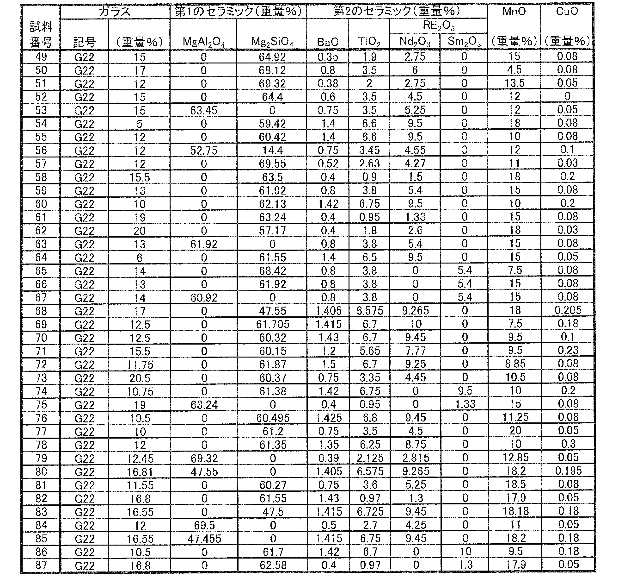
- MgAl 2 O 4 , Mg 2 SiO 4 , BaO, TiO 2 , RE 2 O 3 shown in Table 1 so as to have the compositions shown in Table 2 and Table 3.
- Each powder of 2 O 3 , MnO, and CuO was prepared and mixed, and then an organic solvent and a binder were added to prepare a slurry.
- the slurry was formed into a sheet by the doctor blade method and dried to obtain a ceramic green sheet.
- Samples were appropriately prepared using this ceramic green sheet, and as shown in Tables 4 and 5, the relative dielectric constant ( ⁇ r ), Qf, capacitance temperature coefficient ( ⁇ ), and insulation reliability were evaluated.
- a conductive paste containing Cu is printed on the ceramic green sheet in order to form internal electrodes, and thereafter, lamination, pressure bonding, and firing are performed.
- a multilayer ceramic capacitor serving as a sample was obtained through each step of external electrode formation.
- the distance between adjacent internal electrodes was 10 ⁇ m, and the overlapping electrode area was 4 mm ⁇ .
- the capacitance of the multilayer ceramic capacitor was measured in the range of ⁇ 40 ° C. to 85 ° C., and the capacitance temperature coefficient ⁇ based on 20 ° C. was obtained. About ⁇ , an absolute value exceeding 150 ppm / K was determined to be unacceptable.
- Table 1 to Table 5 show the following.
- samples 1 to 48 shown in Table 2 and Table 4 will be considered.
- any one of the glasses G1 to G36 shown in Table 1 was used.
- the content of “glass” was constant at “13.00 wt%” in all samples 1 to 48.
- Samples 1 and 2 were not sufficiently sintered. This is presumed to be because the glass G1 having a Li 2 O content of less than 0.3% by weight was used.
- Sample 18 was not sufficiently sintered. This is presumably because glass G13 having an alkaline earth metal content of more than 69.0% by weight was used.
- Sample 20 was not fully sintered. This is presumed to be because glass G15 having a B 2 O 3 content of less than 10.0% by weight was used.
- Sample 22 was not fully sintered. This is presumably because glass G17 having a SiO 2 content of more than 30.0% by weight was used.
- Samples 43 and 44 were not vitrified. This is presumed to be because glass G34 having a SiO 2 content of less than 14.2% by weight was used.
- Samples 3 to 5, 8 to 10, 13 to 17, 19 shown in Table 2 and Table 4 other than Samples 1, 2, 6, 7, 11, 12, 18, 20, 22, 24, and 39 to 48 , 21, 23, and 25-38 showed good results in Qf, ⁇ and insulation reliability.
- the alkaline earth metal content is 44.0 to 69.0% by weight
- the SiO 2 content is 14.2 to 30.0% by weight
- the B 2 O 3 content is 10.0 to 20.0% by weight.
- Al 2 O 3 content of 0.5-4.0 wt%
- MgO content of 0.1-5.5 wt% Glasses G2, G3, G4, G6, G7, G9, G10, G11, G12, G14, G16, G18, G20, G21, G22, G23, G24, G25, G26, G27, G28, G29, which satisfy certain conditions This is presumed to be because one of G30 and G31 was used.
- ⁇ r a value of 15 or less was obtained in all samples other than the samples shown in Tables 2 and 4 and the evaluation results of “unsintered” or “not vitrified” were obtained. Obtained.
- Samples 49 to 87 shown in Table 3 and Table 5 will be considered.
- Samples 49 to 87 contain glass G22 shown in Table 1 as “glass”, and contain “glass”, “first ceramic”, “second ceramic”, “MnO”, and “CuO”. Changed the amount.
- Sample 50 did not sinter sufficiently. This is presumed to be because the MnO content was less than 7.5% by weight.
- Sample 54 did not sinter sufficiently. This is presumed to be because the glass content was less than 6% by weight.
- Samples 51 to 53, 55, 56, 59 to 68, 70 shown in Table 3 and Table 5 other than Samples 49, 50, 54, 57, 58, 69, 72, 73, 76 to 78, and 82 to 87 71, 74, 75, and 79-81 showed good results in Qf, ⁇ and insulation reliability.
- the first ceramic content is 47.55 to 69.32 wt%
- the glass content is 6 to 20 wt%
- the MnO content is 7.5 to 18.5 wt%
- the BaO content is 0.00. 38 to 1.43 wt%
- RE 2 O 3 content 1.33 to 9.5 wt%
- TiO 2 content 0.95 to 6.75 wt%
- CuO content 0.23 wt% It is estimated that this is because the condition of% or less was satisfied.
- ⁇ r a value of 15 or less was obtained in all the samples shown in Tables 3 and 5 except for the sample for which the evaluation result of “unsintered” was obtained.
- Example 2 In Experimental Example 2, a glass ceramic for a low dielectric constant ceramic layer was produced as in Experimental Example 1, and in particular, Mg 2 Al 4 Si 5 O 18 and BaAl 2 Si 2 O for this low dielectric constant glass ceramic were produced. The effect of adding at least one of 8 was investigated.
- the above-described cordierite compound Mg 2 Al 4 Si 5 O 18 and celsian compound: BaAl 2 Si 2 O 8 are oxides that give elements, and the above-described oxides are sufficient. Not available were BaO, MgO, Al 2 O 3 and SiO 2 powders.
- Each powder of 2 O 3 , MnO, and CuO was prepared.
- in the samples shown in Table 6 was formulated powders of Mg 2 Al 4 Si 5 O 18 and BaAl 2 Si 2 O 8.
- each powder of MgO, Al 2 O 3 and SiO 2 was further prepared, and the amount of BaO powder was increased. And after mixing these powders, the organic solvent and the binder were added and the slurry was produced.
- the composite oxides such as Mg 2 Al 4 Si 5 O 18 and BaAl 2 Si 2 O 8 have the same effect even when a single oxide as the material is added. Obtained.
- the spinel compound: MgAl 2 O 4 and the forsterite compound: Mg 2 SiO 4 as the first ceramic, BaO, TiO 2 , and RE 2 O 3 as the second ceramic Nd 2 O 3 , MnO, and CuO powders were prepared.
- an organic solvent and a binder were added to prepare a slurry.
- any one of the glasses G1 to G36 shown in Table 1 was used. Note that the content of “glass” was fixed to “9 wt%” in all of the samples 201 to 236.
- Sample 201 was not fully sintered. This is presumed to be because the glass G1 having a Li 2 O content of less than 0.3% by weight was used.
- Sample 213 was not sufficiently sintered. This is presumably because glass G13 having an alkaline earth metal content of more than 69.0% by weight was used.
- Sample 215 was not fully sintered. This is presumed to be because glass G15 having a B 2 O 3 content of less than 10.0% by weight was used.
- Sample 217 was not fully sintered. This is presumably because glass G17 having a SiO 2 content of more than 30.0% by weight was used.
- Sample 234 was not vitrified. This is presumed to be because glass G34 having a SiO 2 content of less than 14.2% by weight was used.
- the alkaline earth metal content is 44.0 to 69.0% by weight
- the SiO 2 content is 14.2 to 30.0% by weight
- the B 2 O 3 content is 10.0 to 20.0% by weight.
- Al 2 O 3 content of 0.5-4.0 wt%
- MgO content of 0.1-5.5 wt% Glasses G2, G3, G4, G6, G7, G9, G10, G11, G12, G14, G16, G18, G20, G21, G22, G23, G24, G25, G26, G27, G28, G29, which satisfy certain conditions This is presumed to be because one of G30 and G31 was used.
- Samples 237 to 273 shown in Table 10 and Table 12 will be considered.
- Samples 237 to 273 each contain “glass”, “first ceramic”, “second ceramic”, “MnO”, and “CuO” while using glass G22 shown in Table 1 as “glass”. Changed the amount.
- ⁇ r is less than 30. This is presumed to be because the BaO content in the second ceramic was less than 2.5% by weight.
- ⁇ r is less than 30. This is presumed to be because the TiO 2 content in the second ceramic was more than 36.4% by weight.
- Sample 245 was not fully sintered. This, Nd 2 O 3 content of the RE 2 O 3 in the second ceramic is presumed to be due was more than 65.3% by weight.
- ⁇ r is less than 30. This, Nd 2 O 3 content of the RE 2 O 3 in the second ceramic is presumed to be due was less than 24.6 wt%.
- Specimen 250 did not sinter sufficiently. This is presumed to be because the glass content was less than 3% by weight.
- the first ceramic content is 1 to 15% by weight
- the glass content is 3 to 15% by weight
- the MnO content is 2.3 to 10% by weight
- the BaO content is 2.5 to 15.7% by weight.
- RE 2 O 3 content is 24.6 to 65.3% by weight
- TiO 2 content is 11.2 to 36.4% by weight
- CuO content is 1.2% by weight or less. This is presumed to be because
- Example 4 In Experimental Example 4, for each of the low dielectric constant ceramic layer and the high dielectric constant ceramic layer, the influence on characteristics when they are co-sintered, in particular, the relative dielectric constant ⁇ r and the capacitance temperature coefficient The effect on ⁇ was investigated.
- 6A and 6B are cross-sectional views showing two types of co-sintered bodies 71 and 72 produced in this experimental example, respectively.
- the co-sintered body 71 shown in FIG. 6A has a structure in which a low dielectric constant ceramic layer 73 having a thickness of 10 ⁇ m is sandwiched between two high dielectric constant ceramic layers 74 and 75 having a thickness of 0.5 mm. . Between the low dielectric constant ceramic layer 73 and the high dielectric constant ceramic layers 74 and 75, internal electrodes 76 and 77 are formed so as to partially face each other. External electrodes 78 and 79 were formed that were electrically connected to electrodes 76 and 77, respectively. The distance between the internal electrodes was 10 ⁇ m, and the electrode area was 4 mm ⁇ .
- the co-sintered body 72 shown in FIG. 6B is opposite to the co-sintered body 71 shown in FIG. 6A in the positional relationship between the low dielectric constant ceramic layer and the high dielectric constant ceramic layer.
- the high dielectric constant ceramic layer 80 having a thickness of 10 ⁇ m was sandwiched between two low dielectric constant ceramic layers 81 and 82 having a thickness of 0.5 mm.
- internal electrodes 83 and 84 are formed so as to face each other in part, and on the opposite end faces, External electrodes 85 and 86 electrically connected to the electrodes 83 and 84, respectively, were formed.
- the planar dimensions of the co-sintered bodies 71 and 72 were 10 mm ⁇ 10 mm.
- the internal electrodes 76, 77, 83 and 84 and the external electrodes 78, 79, 85 and 86 were formed by printing a conductive paste containing Cu as a conductive component.
- the co-sintered body 71 shown in FIG. 6B When evaluating the characteristics of the low dielectric constant glass ceramic produced in Experimental Examples 1 and 2 described above as a co-sintered body, the co-sintered body 71 shown in FIG. When evaluating the characteristics of the high dielectric constant glass ceramic produced in Experimental Example 3 as a co-sintered body, the co-sintered body 72 shown in FIG. 6B was used.
- the relative dielectric constant ⁇ r and the capacitance temperature coefficient ⁇ were determined. The same results were obtained as in the cases of a single glass ceramic and a high dielectric constant glass ceramic.
- the relative dielectric constant ⁇ r was obtained from the following equation by measuring the capacitance value at 1 MHz with an LCR meter and calculating the value and the area and distance of the counter electrode.
- ⁇ r (d ⁇ Cap) / ( ⁇ 0 ⁇ S)
- d is the distance between electrodes [m]
- S is the counter electrode area [m 2 ]
- Cap is the capacitance [F]
- ⁇ 0 is the dielectric constant of vacuum (8.854 ⁇ 10 ⁇ 12 [F /]. ).
- Table 3 attached with the sample numbers shown in the column of “Low dielectric constant layer sample number” in Table 13 A combination of the low dielectric constant glass ceramic shown and the high dielectric constant glass ceramic shown in Table 10 to which the sample number shown in the column of “High dielectric constant sample number” in Table 13 is attached is shown in FIG. And the co-sintered bodies 71 and 72 as shown to (B), respectively were produced.
- the co-sintered body 71 shown in FIG. 6A was used to evaluate the insulation reliability of the low dielectric constant glass ceramic, and the co-sintered body 72 shown in FIG. The insulation reliability of the high dielectric constant glass ceramic was evaluated.
- each voltage of DC 200 V, 100 V and 50 V is applied between the external electrodes 78 and 79 of the co-sintered body 71 or between the external electrodes 85 and 86 of the co-sintered body 72 at a temperature of 150 ° C. was applied for 100 hours. Insulation resistance was measured after the test, and when log (IR [ ⁇ ]) after this test was less than 11, it was determined to be unacceptable.
- Warpage is a composite substrate in which a low dielectric constant ceramic layer having a thickness of 0.5 mm and a high dielectric constant ceramic layer having a thickness of 0.5 mm are laminated to have a planar dimension of 50 mm ⁇ 50 mm and a thickness of 1 mm.
- the highest point height was measured, and the value obtained by subtracting the thickness of the composite substrate from this was determined as the amount of warpage.
- the amount of warpage is 0.1 mm or less, it is determined to be acceptable, “ ⁇ ” is displayed in the “warp” column of Table 16, and the amount of warpage exceeding 0.1 mm is determined to be unacceptable.
- “X” is displayed in the same column.
- the samples 506, 507, 511 and 512 that satisfy the condition of 1.5 ⁇ M L / M H ⁇ 3.6 are particularly “high dielectric constant side reliability”. With respect to, an evaluation of “ ⁇ ” or “ ⁇ ” was obtained.
Landscapes
- Engineering & Computer Science (AREA)
- Chemical & Material Sciences (AREA)
- Ceramic Engineering (AREA)
- Materials Engineering (AREA)
- Organic Chemistry (AREA)
- Power Engineering (AREA)
- Manufacturing & Machinery (AREA)
- Chemical Kinetics & Catalysis (AREA)
- Geochemistry & Mineralogy (AREA)
- General Chemical & Material Sciences (AREA)
- Life Sciences & Earth Sciences (AREA)
- Structural Engineering (AREA)
- Microelectronics & Electronic Packaging (AREA)
- Inorganic Chemistry (AREA)
- Ceramic Capacitors (AREA)
- Compositions Of Oxide Ceramics (AREA)
- Inorganic Insulating Materials (AREA)
- Glass Compositions (AREA)
- Fixed Capacitors And Capacitor Manufacturing Machines (AREA)
- Parts Printed On Printed Circuit Boards (AREA)
Abstract
共焼成された低誘電率セラミック層と高誘電率セラミック層とを備え、低誘電率セラミック層および高誘電率セラミック層の各々において相応の特性が得られる、複合積層セラミック電子部品を提供する。 低誘電率セラミック層(3)と高誘電率セラミック層(4)とを、MgAl2O4および/またはMg2SiO4からなる第1のセラミックと、BaO、RE2O3(REは希土類元素)およびTiO2からなる第2のセラミックと、RO(Rはアルカリ土類金属)を44.0~69.0重量%、SiO2を14.2~30.0重量%、B2O3を10.0~20.0重量%、Al2O3を0.5~4.0重量%、Li2Oを0.3~7.5重量%、MgOを0.1~5.5重量%それぞれ含むガラスと、MnOとを含む、ガラスセラミックから構成し、低誘電率セラミック層(3)と高誘電率セラミック層(4)とでガラス等の含有比率を異ならせる。
Description
この発明は、たとえばマイクロ波用共振器、フィルタまたはコンデンサなどを内部に構成する多層セラミック基板のような積層セラミック電子部品に関するもので、特に、比較的低い比誘電率を有する低誘電率セラミック層と比較的高い比誘電率を有する高誘電率セラミック層とが積層された複合構造を有する複合積層セラミック電子部品に関するものである。
近年、電子機器の小型化、軽量化および薄型化に伴って、電子機器に用いられる電子部品の小型化が求められている。しかしながら、従来、コンデンサや共振器などの電子部品は、それぞれ個別に構成されており、これらの部品を小型化しただけでは、電子機器の小型化には限界がある。そこで、コンデンサや共振器などの素子を内部に構成する多層セラミック基板が種々提案されている。
また、多層セラミック基板のより一層の小型化および近年の高周波化の流れに対応するため、低誘電率セラミック層と高誘電率セラミック層とが積層された複合構造を有する多層セラミック基板も種々提案されている。たとえば、特開2002-29827号公報(特許文献1)および特開2003-63861号公報(特許文献2)に記載されるように、配線が形成されたり、半導体素子などが実装されたりする低誘電率セラミック層に挟まれて、高誘電率で低誘電損失の材料からなる高誘電率セラミック層を配置し、ここに、コンデンサや共振器などの素子を構成している、多層セラミック基板が提案されている。
上記特許文献1および特許文献2には、また、低誘電率セラミック層を形成するのに適したガラスセラミック組成物または高誘電率セラミック層を形成するのに適したガラスセラミック組成物も記載されている。
より具体的には、特許文献1では、その請求項1において、MgAl2O4系セラミックとガラスとを含む、ガラスセラミック組成物が記載されている。より詳細には、MgAl2O4系セラミック粉末と、酸化ケイ素をSiO2換算で13~50重量%、酸化ホウ素をB2O3換算で8~60重量%、酸化アルミニウムをAl2O3換算で0~20重量%、酸化マグネシウムをMgO換算で10~55重量%含むガラス粉末とを含む、ガラスセラミック組成物が記載されている。
また、特許文献1では、その請求項2において、アルカリ土類金属酸化物を20重量%以下の割合でさらに含んでもよいことが記載され、その請求項6において、ガラスの含有量は全体の20~80重量%であることが好ましい旨記載されている。
特許文献1に記載のガラスセラミック組成物によれば、その焼結体において、比誘電率がたとえば8以下というように、比較的低い比誘電率が得られ、高周波用途に適したものとすることができる。
次に、特許文献2では、比較的高い比誘電率を有する高誘電率セラミック層を構成する高誘電率材料として、BaO-TiO2-RE2O3(REは希土類元素)系誘電体およびガラスを含むものが記載されている。ガラスは、特許文献2の請求項2によれば、10~25重量%のSiO2と、10~40重量%のB2O3と、25~55重量%のMgOと、0~20重量%のZnOと、0~15重量%のAl2O3と、0.5~10重量%のLi2Oと、0~10重量%のRO(RはBa、SrおよびCaの少なくとも1種)とを含む。また、特許文献2の請求項4に記載されるように、ガラスの含有量は、15~35重量%であることが好ましい。
他方、上記低誘電率セラミック層を構成する低誘電率材料として、特許文献2には、特許文献1と類似の材料が記載されている。
本件発明者は、上記のような特許文献1および2に記載の各ガラスセラミック組成物について実験を重ねた結果、まず、絶縁信頼性について、なお改善されるべき点を見出した。その原因は以下のように推測される。
特許文献1および2の各々に記載のガラスセラミック組成物に含まれるガラスは、1000℃以下の温度での焼成を可能にするためのものであるが、結晶化しやすい組成になっている。特許文献1および2に記載のガラスセラミック組成物では、焼成過程でガラス成分とセラミック成分とが反応して結晶が析出されるため、焼成完了時点での結晶の量とガラス成分の量を安定化させることが困難である。そして、このような焼成完了時点での結晶の量とガラス成分の量の不安定さが、絶縁信頼性を低下させていると推測される。
たとえば、特許文献1および2の各々に記載のガラスセラミック組成物に含まれるガラスはMgOを比較的多く含むが、このように、ガラス中のMgOが多いと、ガラス成分からMgAl2O4および/またはMg2SiO4の結晶が析出されると考えられ、このことが絶縁信頼性の低下を招いていると推測される。
また、特に特許文献2に記載の高誘電率材料は、1000℃以下の温度での焼成を可能とするため、ガラスの添加が必要であり、他方、比誘電率を高くするため、BaO-TiO2-RE2O3系誘電体を含む必要がある。しかし、このBaO-TiO2-RE2O3系誘電体から遊離したTiイオンは、酸素欠陥を引き起こす。そして、このような酸素欠陥は、特に、高温・高電圧・長時間等の使用下での絶縁信頼性を低下させる原因となり得る。
また、本件発明者は、実験を重ねた結果、特許文献1および2に記載の各ガラスセラミック組成物が有する組成では、比誘電率の低いものから高いものまで、幅広い範囲で所望の比誘電率のものを安定して得ることが困難であるといった問題を認識するに至った。
すなわち、特許文献1および2に記載のガラスセラミック組成物に含まれるガラスは、前述のとおり、焼成過程において、セラミック成分と反応して結晶化しやすい。結晶が析出されてしまうと、比誘電率が変化するため、所望の比誘電率を得ることが困難である。
また、特許文献1および2に記載のガラスセラミック組成物に含まれるガラスは、MgAl2O4系セラミックやBaO-TiO2-RE2O3系誘電体に対する濡れ性が良好ではない。そのため、ガラスを比較的多く添加しなければ、ガラスセラミック組成物を焼結させることができない。しかし、ガラスの添加量が多いと、比誘電率が低下してしまう。このことから、特に高誘電率材料を作製することが困難である。
さらに、複合積層セラミック電子部品独自の課題として、低誘電率セラミック層単独の場合に得られる特性や、高誘電率セラミック層単独の場合に得られる特性が、低誘電率セラミック層と高誘電率セラミック層との共焼成の場合にほぼ維持されるかどうかについても考慮されなければならない。特に、特許文献1および2の各々に記載のガラスセラミック組成物に含まれるガラスが結晶化しやすい組成になっているため、焼成完了時点での結晶の量とガラス成分の量を安定化させることが困難である点からすると、低誘電率セラミック層と高誘電率セラミック層との共焼成の結果、各セラミック層の単独での特性が失われている可能性も十分にあり得るものと推測される。
そこで、この発明の目的は、低誘電率セラミック層と高誘電率セラミック層とが共焼成されることができ、低誘電率セラミック層および高誘電率セラミック層の各々において相応の特性が得られる、複合積層セラミック電子部品を提供しようとすることである。
この発明は、積層された低誘電率セラミック層と高誘電率セラミック層とを備える、複合積層セラミック電子部品に向けられるものであって、上述した技術的課題を解決するため、次のような構成を備えることを特徴としている。
低誘電率セラミック層と高誘電率セラミック層とは、いずれも、(1)MgAl2O4およびMg2SiO4の少なくとも一方からなる第1のセラミックと、(2)BaO、RE2O3(REは希土類元素)およびTiO2からなる第2のセラミックと、(3)RO(RはBa、CaおよびSrから選ばれる少なくとも1種のアルカリ土類金属)を44.0~69.0重量%、SiO2を14.2~30.0重量%、B2O3を10.0~20.0重量%、Al2O3を0.5~4.0重量%、Li2Oを0.3~7.5重量%、およびMgOを0.1~5.5重量%それぞれ含むガラスと、(4)MnOとを含む、ガラスセラミックからなる。
そして、低誘電率セラミック層は、上記第1のセラミックを47.55~69.32重量%含み、上記ガラスを6~20重量%含み、上記MnOを7.5~18.5重量%含み、上記第2のセラミックとして、BaOを0.38~1.43重量%、RE2O3を1.33~9.5重量%、およびTiO2を0.95~6.75重量%それぞれ含み、比誘電率が15以下である。
他方、高誘電率セラミック層は、上記第1のセラミックを1~15重量%含み、上記ガラスを3~15重量%含み、上記MnOを2.3~10重量%含み、上記第2のセラミックとして、BaOを2.5~15.7重量%、RE2O3を24.6~65.3重量%、およびTiO2を11.2~36.4重量%それぞれ含み、比誘電率が30以上である。
好ましくは、低誘電率セラミック層に含まれるガラスの含有量GLおよび高誘電率セラミック層に含まれるガラスの含有量GHは、1.0≦GL/GH≦2.0の条件を満たすようにされる。後述する実験例からわかるように、この条件を満たせば、特に低誘電率セラミック層の絶縁信頼性を向上させることができる。
また、好ましくは、低誘電率セラミック層に含まれるMnOの含有量MLおよび高誘電率セラミック層に含まれるMnOの含有量MHは、1.5≦ML/MH≦3.6の条件を満たすようにされる。後述する実験例からわかるように、この条件を満たせば、特に高誘電率セラミック層の絶縁信頼性を向上させることができる。
より好ましくは、上記2つの条件を双方とも満たすようにされる。これによって、後述する実験例からわかるように、低誘電率セラミック層および高誘電率セラミック層の双方について、絶縁信頼性をより向上させることができる。
また、低誘電率セラミック層は、さらに、Mg2Al4Si5O18およびBaAl2Si2O8の少なくとも一方を3.0~20.0重量%含むことが好ましい。これによって、後述する実験例からわかるように、複合積層セラミック電子部品において、反りをより生じにくくすることができる。
低誘電率セラミック層は、さらに、CuOを0.23重量%以下含んでもよく、また、高誘電率セラミック層は、さらに、CuOを1.2重量%以下含んでもよい。
この発明によれば、低誘電率セラミック層および高誘電率セラミック層が共通する元素を含むガラスセラミックからなるので、低誘電率セラミック層と高誘電率セラミック層とを問題なく共焼結させることができる。
また、低誘電率セラミック層および高誘電率セラミック層の各々について、そこに含まれるガラスが結晶化しにくく、また、MnOを含んでいるため、絶縁信頼性を高くすることができる。
また、低誘電率セラミック層においては、比誘電率が15以下で、絶縁信頼性が高く、Qf値が高く、静電容量温度係数(TCC)が絶対値で150ppm/K以下である、といった特性を得ることができる。
他方、高誘電率セラミック層においては、比誘電率が30以上で、絶縁信頼性が高く、Qf値が高く、静電容量温度係数(TCC)が絶対値で150ppm/K以下である、といった特性を得ることができる。
図1および図2を参照して、この発明に係る複合積層セラミック電子部品の一例としての多層セラミック基板2を備えるセラミック多層モジュール1について説明する。
セラミック多層モジュール1に備える多層セラミック基板2は、積層された複数の低誘電率セラミック層3および積層された複数の高誘電率セラミック層4を備え、複数の低誘電率セラミック層3は、複数の高誘電率セラミック層4を挟むように位置し、これらは共焼成される。
低誘電率セラミック層3と高誘電率セラミック層4とは、いずれも、
(1)MgAl2O4およびMg2SiO4の少なくとも一方からなる第1のセラミックと、
(2)BaO、RE2O3(REは希土類元素)およびTiO2からなる第2のセラミックと、
(3)RO(RはBa、CaおよびSrから選ばれる少なくとも1種のアルカリ土類金属)を44.0~69.0重量%、SiO2を14.2~30.0重量%、B2O3を10.0~20.0重量%、Al2O3を0.5~4.0重量%、Li2Oを0.3~7.5重量%、およびMgOを0.1~5.5重量%それぞれ含むガラスと、
(4)MnOと
を含む、ガラスセラミックからなる。
(1)MgAl2O4およびMg2SiO4の少なくとも一方からなる第1のセラミックと、
(2)BaO、RE2O3(REは希土類元素)およびTiO2からなる第2のセラミックと、
(3)RO(RはBa、CaおよびSrから選ばれる少なくとも1種のアルカリ土類金属)を44.0~69.0重量%、SiO2を14.2~30.0重量%、B2O3を10.0~20.0重量%、Al2O3を0.5~4.0重量%、Li2Oを0.3~7.5重量%、およびMgOを0.1~5.5重量%それぞれ含むガラスと、
(4)MnOと
を含む、ガラスセラミックからなる。
このように、低誘電率セラミック層3および高誘電率セラミック層4が共通する元素を含むガラスセラミックからなるので、低誘電率セラミック層3と高誘電率セラミック層4とを問題なく共焼結させることができる。
また、この発明において用いられる上述のガラスセラミックによれば、後述する実験例から明らかになるように、次のような効果が奏される。
(A)絶縁信頼性が高い。
このガラスセラミックに含まれるガラスは、結晶化しにくい組成となっている。そのため、焼成完了時点での結晶量とガラス成分量が安定し、よって絶縁信頼性を向上させることができる。このガラスは、特許文献1および2に記載のものに含まれるガラスに比べて、MgO含有量が少ないため、MgAl2O4やMg2SiO4といった結晶の析出を抑えることができ、しかも、RO含有量を多くすることで、結晶化しない組成になるようにすることができるからである。
また、上記ガラスセラミック組成物は、MnOを含んでいる。特許文献1および2に記載のものは、MnOを含まない。Ti酸化物の還元により生じるTiイオンは、酸素欠陥を引き起こし、高温・高電圧・長時間等の使用下での絶縁信頼性を低下させる原因となり得る。この発明では、MnがTiサイトに置換することによって酸素欠陥が生じるのを抑制する。このことも、絶縁信頼性の向上に寄与しているものと推測される。
(B)比誘電率の低いものから高いものまで、幅広い範囲で所望の比誘電率の製品を容易に得ることができる。
前述したように、特許文献1および2に記載のガラスは、セラミック成分と反応して結晶化しやすく、そのため、比誘電率が変化しやすい。これに対し、この発明において用いられるガラスセラミックに含まれるガラスは、結晶化しにくいため、所望の比誘電率を有する製品を作製することが容易である。
また、この発明において用いられるガラスセラミックに含まれるガラスは、上記第1のセラミックおよび上記第2のセラミックに対する濡れ性が高く、かつ反応性が低いガラスである。したがって、当該ガラスセラミックは、ガラス成分を少なくしても焼結させることができ、逆に、ガラス成分を多くしても反応しにくく安定である。そのため、ガラスセラミックにおいて、セラミック成分およびガラス成分の各々の含有量を幅広く調整することが可能であり、よって、セラミック成分およびガラス成分の各含有量を調整するだけで、低誘電率品から高誘電率品まで幅広い製品を容易に提供することができる。すなわち、以下に説明するように、低誘電率セラミック層3を構成するのに適したガラスセラミックと高誘電率セラミック層4を構成するのに適したガラスセラミックとを提供することができる。
なお、この発明において用いられるガラスセラミックは、焼成前後で大きく組成が変動しない。ガラス中のB2O3やLi2Oは焼成時に揮発する場合があるが、その場合であっても、焼成後におけるその他の成分の比率は焼成前とほぼ変わらない。
低誘電率セラミック層3を構成するガラスセラミックは、第1のセラミックを47.55~69.32重量%含み、ガラスを6~20重量%含み、MnOを7.5~18.5重量%含み、第2のセラミックとして、BaOを0.38~1.43重量%、RE2O3を1.33~9.5重量%、およびTiO2を0.95~6.75重量%それぞれ含んでいる。
低誘電率セラミック層3においては、比誘電率が15以下で、絶縁信頼性が高く、Qf値が高く、静電容量温度係数(TCC)が絶対値で150ppm/K以下である、といった特性を得ることができる。
他方、高誘電率セラミック層4を構成するガラスセラミックは、第1のセラミックを1~15重量%含み、ガラスを3~15重量%含み、MnOを2.3~10重量%含み、第2のセラミックとして、BaOを2.5~15.7重量%、RE2O3を24.6~65.3重量%、およびTiO2を11.2~36.4重量%それぞれ含んでいる。
高誘電率セラミック層4においては、比誘電率が30以上で、絶縁信頼性が高く、Qf値が高く、静電容量温度係数(TCC)が絶対値で150ppm/K以下である、といった特性を得ることができる。
好ましくは、低誘電率セラミック層3に含まれるガラスの含有量GLおよび高誘電率セラミック層4に含まれるガラスの含有量GHは、1.0≦GL/GH≦2.0の条件を満たすようにされる。後述する実験例からわかるように、この条件を満たせば、特に低誘電率セラミック層3の絶縁信頼性を向上させることができる。これは、低誘電率セラミック層3のガラス成分と高誘電率セラミック層4のガラス成分との間での相互拡散を抑えることができるためであると推測される。
また、好ましくは、低誘電率セラミック層3に含まれるMnOの含有量MLおよび高誘電率セラミック層4に含まれるMnOの含有量MHは、1.5≦ML/MH≦3.6の条件を満たすようにされる。後述する実験例からわかるように、この条件を満たせば、特に高誘電率セラミック層4の絶縁信頼性を向上させることができる。これは、低誘電率セラミック層3のMnO成分と高誘電率セラミック層4のMnO成分との間での相互拡散を抑えることができるためであると推測される。
より好ましくは、上記2つの条件を双方とも満たすようにされる。これによって、後述する実験例からわかるように、低誘電率セラミック層3および高誘電率セラミック層4の双方について、絶縁信頼性をより向上させることができる。
また、低誘電率セラミック層3は、さらに、Mg2Al4Si5O18およびBaAl2Si2O8の少なくとも一方を3.0~20.0重量%含むことが好ましい。これによって、後述する実験例からわかるように、多層セラミック基板2において、反りをより生じにくくすることができる。
低誘電率セラミック層3は、さらに、CuOを0.23重量%以下含んでもよく、また、高誘電率セラミック層4は、さらに、CuOを1.2重量%以下含んでもよい。
多層セラミック基板2は、種々の配線導体を備えている。配線導体としては、典型的には、セラミック層3および4間の特定の界面に沿って形成される内部導体膜6、セラミック層3および4の特定のものを貫通するように延びるビアホール導体7、および多層セラミック基板2の外表面上に形成される外部導体膜8がある。
上述の内部導体膜6のうち、高誘電率セラミック層4に関連して設けられるもののいくつかは、静電容量を与えるように配置され、それによってコンデンサ素子を構成している。
多層セラミック基板2の上面には、複数の電子部品9~17が搭載されている。図示された電子部品9~17のうち、たとえば、電子部品9はダイオードであり、電子部品11は積層セラミックコンデンサであり、電子部品16は半導体ICである。これら電子部品9~17は、多層セラミック基板2の上面に形成された外部導体膜8の特定のものに電気的に接続されながら、多層セラミック基板2の内部に形成された配線導体とともに、セラミック多層モジュール1にとって必要な回路を構成している。
多層セラミック基板2の上面には、電子部品9~17をシールドするための導電性キャップ18が固定されている。導電性キャップ18は、前述したビアホール導体7の特定のものに電気的に接続されている。
また、セラミック多層モジュール1は、多層セラミック基板2の下面上に形成された外部導体膜8の特定のものを接続用端子として、図示しないマザーボード上に実装される。
多層セラミック基板2は、周知のセラミック積層一体焼成技術を用いて製造することができる。
すなわち、まず、低誘電率セラミック層3のためのセラミックグリーンシートが作製される。より具体的には、上述したガラスセラミックを与える原料組成物に、バインダ樹脂および溶剤からなる有機ビヒクルを添加し、セラミックスラリーを得る。このセラミックスラリーを、たとえばドクターブレード法によってシート状に成形し、乾燥した後、所定の寸法に打ち抜くことによって、セラミックグリーンシートを得る。そして、このセラミックグリーンシートに、配線導体を形成するため、たとえば銅または銀を主成分とする導電性ペーストを、所望のパターンをもって付与する。
他方、高誘電率セラミック層4を構成するガラスセラミックを与える原料組成物を含むセラミックグリーンシートが、低誘電率セラミック層3のためのセラミックグリーンシートの場合と同様の方法で作製される。そして、このセラミックグリーンシートに、配線導体を形成するため、たとえば銅または銀を主成分とする導電性ペーストを、所望のパターンをもって付与する。
次に、上述のようにして得られた低誘電率セラミック層3のためのセラミックグリーンシートおよび高誘電率セラミック層4のためのセラミックグリーンシートを、それぞれ、所定の順序で所定の枚数積層し、次いで、厚み方向に加圧する。
次に、上述のようにして得られた生の積層体を1000℃以下、たとえば800~1000℃の温度で焼成することにより、多層セラミック基板2を得ることができる。ここで、焼成は、配線導体が銅を主成分とする場合、窒素雰囲気等の非酸化性雰囲気中で実施され、銀を主成分とする場合には、大気等の酸化性雰囲気中で実施される。
次に、多層セラミック基板2の表面に、半田付け等を適用して、電子部品9~17を搭載し、導電性キャップ18を取り付けることによって、セラミック多層モジュール1が完成される。
以上のようなセラミック多層モジュール1によれば、多層セラミック基板2に備える低誘電率セラミック層3においては、比誘電率が15以下で、Qf値が高く、静電容量温度係数が絶対値で150ppm/K以下であり、他方、高誘電率セラミック層4においては、比誘電率が30以上で、Qf値が高く、静電容量温度係数(TCC)が絶対値で150ppm/K以下であるので、高周波用途に適し、かつ信頼性に優れたものとすることができる。また、セラミック多層モジュール1の絶縁信頼性を優れたものとすることができる。
次に、図3ないし図5を参照して、この発明に係る複合積層セラミック電子部品の他の例としてのLCフィルタ21について説明する。
LCフィルタ21は、図3に示すように、複数の積層されたガラスセラミック層をもって構成される積層構造物としての部品本体23を備え、この部品本体23の外表面上であって、各端部には、端子電極24および25が設けられ、各側面の中間部には、端子電極26および27が設けられている。
LCフィルタ21は、図4に示すように、端子電極24および25の間に直列接続された2つのインダクタンスL1およびL2を構成し、インダクタンスL1およびL2の接続点と端子電極26および27との間にキャパシタンスCを構成するものである。
図5に示すように、部品本体23は、複数の積層されたセラミック層28~40を備えている。なお、セラミック層の積層数は図示したものに限定されない。
セラミック層28~40の各々は、ガラスセラミックを与える原料組成物に、バインダ樹脂および溶剤からなる有機ビヒクルを添加し、これらを混合して得られたセラミックスラリーを、ドクターブレード法によってシート状に成形し、乾燥した後、所定の大きさに打ち抜くことによって得られたセラミックグリーンシートを焼成して得られたものである。
また、図4に示すようなインダクタンスL1およびL2ならびにキャパシタンスCを与えるため、セラミック層28~40の特定のものに関連して、以下のような態様で配線導体が設けられる。
セラミック層30には、インダクタンスL1の一部を構成するコイルパターン41が形成されるとともに、このコイルパターン41の一方端から延びる引出しパターン42が形成され、コイルパターン41の他方端には、ビアホール導体43が設けられる。引出しパターン42は端子電極24に接続される。
セラミック層31には、インダクタンスL1の一部を構成するコイルパターン44が形成されるとともに、その一方端には、ビアホール導体45が設けられる。コイルパターン44の他方端は、前述したビアホール導体43に接続される。
セラミック層32には、上述のビアホール導体45に接続されるビアホール導体46が設けられる。
セラミック層33には、キャパシタンスCの一部を構成するコンデンサパターン47が形成されるとともに、コンデンサパターン47から延びる引出しパターン48および49が形成される。引出しパターン48および49は端子電極26および27に接続される。また、セラミック層33には、前述したビアホール導体46に接続されるビアホール導体50が設けられる。
セラミック層34には、キャパシタンスCの一部を構成するコンデンサパターン51が形成されるとともに、コンデンサパターン51に接続されるビアホール導体52が設けられる。コンデンサパターン51は、前述したビアホール導体50に接続される。
セラミック層35には、キャパシタンスCの一部を構成するコンデンサパターン53が形成されるとともに、このコンデンサパターン53から延びる引出しパターン54および55が形成される。引出しパターン54および55は端子電極26および27に接続される。また、このセラミック層35には、前述したビアホール導体52に接続されるビアホール導体56が設けられる。
セラミック層36には、上述のビアホール導体56に接続されるビアホール導体57が設けられる。
セラミック層37には、インダクタンスL2の一部を構成するコイルパターン58が形成されるとともに、その一方端には、ビアホール導体59が設けられる。コイルパターン58の他方端は、前述したビアホール導体57に接続される。
セラミック層38には、インダクタンスL2の一部を構成するコイルパターン60が形成されるとともに、このコイルパターン60の一方端から延びる引出しパターン61が形成される。引出しパターン61は端子電極25に接続される。コイルパターン60の他方端は、前述したビアホール導体59に接続される。
以上のような配線導体としての、コイルパターン41、44、58および60、引出しパターン42、48、49、54、55および61、ビアホール導体43、45、46、50、52、56、57および59、ならびにコンデンサパターン47、51および53を形成するにあたっては、たとえば銅または銀を主成分とする導電性ペーストが用いられ、この導電性ペーストの付与のため、たとえばスクリーン印刷が適用される。
そして、部品本体23を得るため、上述したセラミック層28~40の各々となるべきセラミックグリーンシートが所定の順序で積層され、厚み方向に加圧され、その後、1000℃以下、たとえば800~1000℃の温度で焼成される。ここで、焼成は、前述したセラミック多層モジュール1の場合と同様、配線導体が銅を主成分とする場合には、窒素雰囲気等の非酸化性雰囲気で実施され、銀を主成分とする場合には、大気等の酸化性雰囲気中で実施される。
また、部品本体23の外表面上にある端子電極24~27の形成のため、たとえば、銅または銀を主成分とする導電性ペーストの塗布および焼付け、または、蒸着、めっきもしくはスパッタリングなどの薄膜形成法等が適用される。
以上のようなLCフィルタ21において、セラミック層28~40のうち、特にキャパシタンスCの構成に直接寄与するセラミック層33および34については、前述の図1に示したセラミック多層モジュール1に備える高誘電率セラミック層4を構成するものと同様の高誘電率セラミック材料から構成され、その他のセラミック層28~32および35~40は、セラミック多層モジュール1に備える低誘電率セラミック層3を構成するものと同様の低誘電率セラミック材料から構成される。
この発明は、図示したようなセラミック多層モジュール1またはLCフィルタ21以外の複合積層セラミック電子部品にも適用され得る。
次に、この発明において用いられるガラスセラミックによって得られる特性、および当該ガラスセラミックを用いて構成される複合積層セラミック電子部品が有する特性を評価するために実施した実験例について説明する。
[ガラスの準備]
まず、ガラスセラミックに含まれるガラスであって、以下の実験例において共通して用いられるガラスとして、表1に示すような組成をもって調合したものを1100~1400℃の温度で溶融し、急冷してガラス化した後、湿式粉砕することによって、種々の組成のガラス粉末を用意した。
まず、ガラスセラミックに含まれるガラスであって、以下の実験例において共通して用いられるガラスとして、表1に示すような組成をもって調合したものを1100~1400℃の温度で溶融し、急冷してガラス化した後、湿式粉砕することによって、種々の組成のガラス粉末を用意した。

[実験例1]
実験例1では、低誘電率セラミック層のためのガラスセラミック単体での評価を行なった。
実験例1では、低誘電率セラミック層のためのガラスセラミック単体での評価を行なった。
まず、第1のセラミックとして、MgCO3とAl2O3とを所定の比率で調合して、仮焼し、湿式粉砕することによって、スピネル化合物:MgAl2O4を作製するとともに、MgCO3とSiO2とを所定の比率で調合して、仮焼し、湿式粉砕することによって、フォルステライト化合物:Mg2SiO4を作製した。
次に、表2および表3に示す組成となるように、表1に示したガラス、MgAl2O4、Mg2SiO4、BaO、TiO2、RE2O3としてのNd2O3およびSm2O3、MnO、ならびにCuOの各粉末を調合し、混合した後、有機溶剤およびバインダを加えて、スラリーを作製した。

次に、上記スラリーをドクターブレード法によってシート状に成形し、乾燥することによって、セラミックグリーンシートを得た。このセラミックグリーンシートを用いて適宜試料を作製し、表4および表5に示すように、比誘電率(εr)、Qf、静電容量温度係数(β)および絶縁信頼性を評価した。
より具体的は、εrおよびQfの測定にあたっては、上記セラミックグリーンシートをカットし、積層し、圧着することによって、0.6mm×50mm×50mmの寸法を有する圧着体を作製した。これを990℃の温度で焼成することによって、試料となるセラミック基板を得た。このセラミック基板を用いて、空洞共振器法により、εrおよびQfを測定した。このとき、測定周波数を約25GHzとした。
この実験例では、εrが15以下の誘電体材料を得ることを目的とした。Qfについては、5000未満のものを不合格と判定した。
βの測定および絶縁信頼性の評価にあたっては、上記セラミックグリーンシートをカットした後、内部電極を形成するため、Cuを含む導電性ペーストをセラミックグリーンシート上に印刷し、その後、積層、圧着、焼成、外部電極形成の各工程を経て、試料となる積層セラミックコンデンサを得た。この積層セラミックコンデンサにおける隣り合う内部電極間距離は10μm、重なり合う電極面積は4mm□であった。
そして、上記積層セラミックコンデンサ静電容量を-40℃~85℃の範囲で測定し、20℃を基準とする静電容量温度係数βを求めた。βについては、絶対値で150ppm/Kを超えるものを不合格と判定した。
また、上記積層セラミックコンデンサについて、150℃の温度下で、DC200Vを100時間印加する試験後において絶縁抵抗を測定し、この試験後のlog (IR[Ω])が11未満となった場合は、不合格と判定し、表4および表5の「絶縁信頼性」の欄において「×」で表示し、他方、log (IR[Ω])が11以上となった場合は、合格と判定し、表4および表5の「絶縁信頼性」の欄において「○」で表示した。
なお、十分に焼結しなかった試料については、表4および表5の「備考」欄に「未焼結」と表示し、また、ガラスがガラス化しなかった試料については、「備考」欄に「ガラス化しない」と表示し、これらの試料では、εr、Qf、βおよび絶縁信頼性の各評価を行なわなかった。また、「備考」欄には、この実験例において不合格となった試料についての不合格理由が簡潔に記載されている。
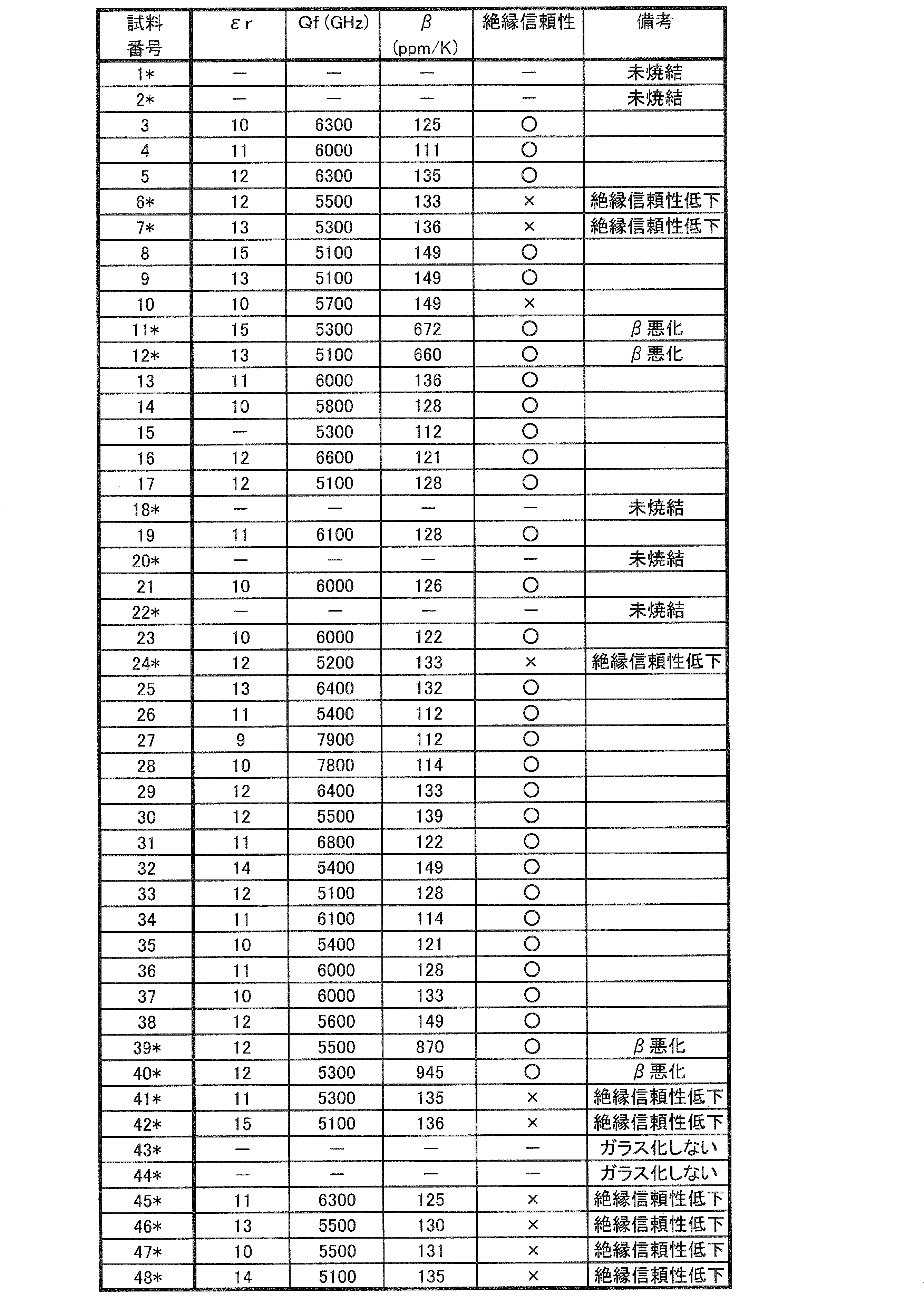
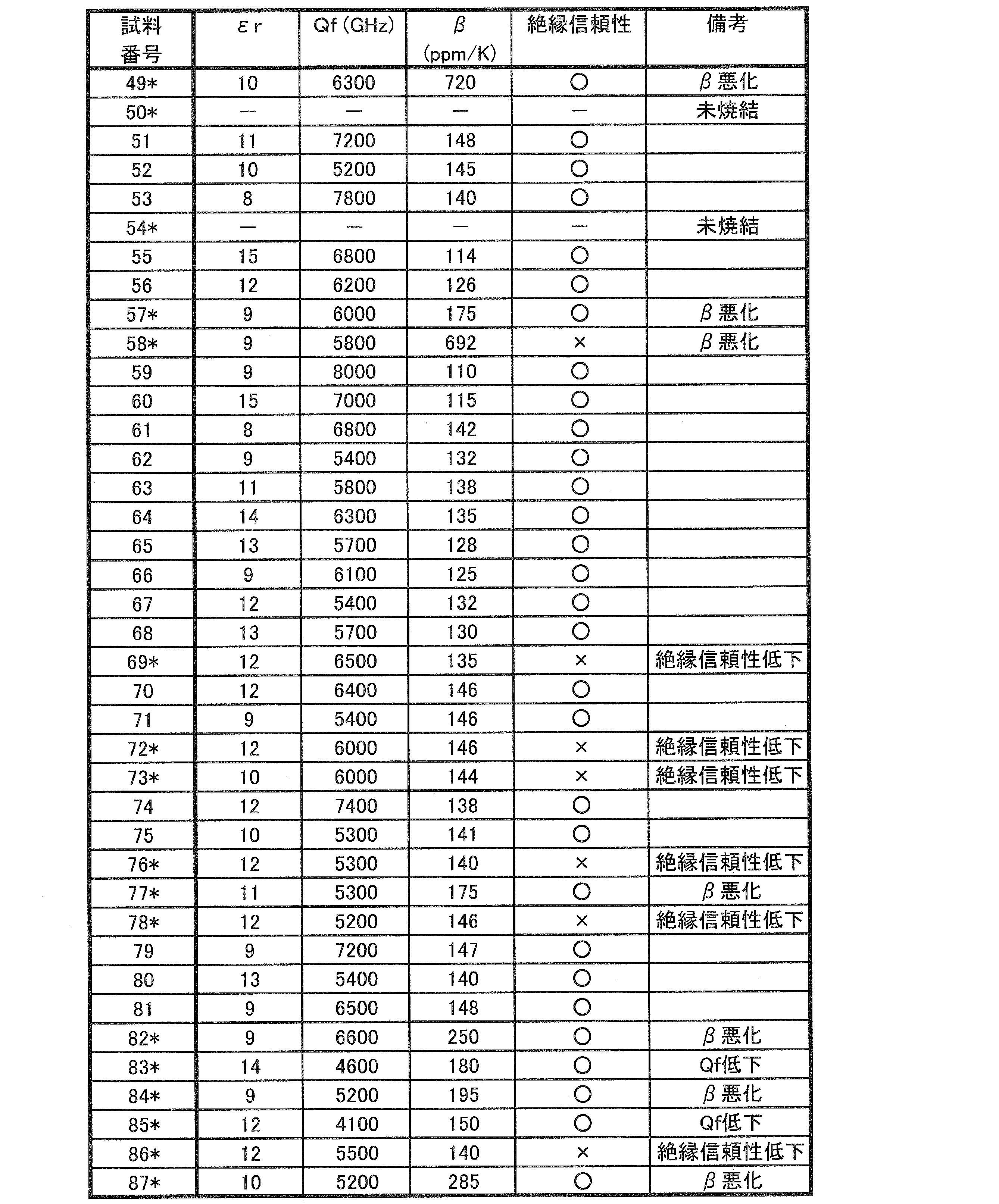
表4および表5において、この実験例で不合格と判定された試料については、その試料番号に*が付されている。
表1ないし表5から、以下のことがわかる。
まず、表2および表4に示した試料1~48について考察する。試料1~48では、表1に示したガラスG1~G36のすべてについて、そのいずれかが用いられた。なお、「ガラス」の含有量については、試料1~48のすべてにおいて、「13.00重量%」と一定とした。
試料1および試料2では、十分に焼結しなかった。これは、Li2O含有量が0.3重量%より少ないガラスG1を用いたためであると推測される。
試料6および試料7では、絶縁信頼性が低下した。これは、Li2O含有量が7.5重量%より多いガラスG5を用いたためであると推測される。
試料11および試料12では、静電容量温度係数βが悪化した。これは、アルカリ土類金属含有量が44.0重量%より少ないガラスG8を用いたためであると推測される。
試料18では、十分に焼結しなかった。これは、アルカリ土類金属含有量が69.0重量%より多いガラスG13を用いたためであると推測される。
試料20では、十分に焼結しなかった。これは、B2O3含有量が10.0重量%より少ないガラスG15を用いたためであると推測される。
試料22では、十分に焼結しなかった。これは、SiO2含有量が30.0重量%より多いガラスG17を用いたためであると推測される。
試料24では、絶縁信頼性が低下した。これは、B2O3含有量が20.0重量%より多いガラスG19を用いたためであると推測される。
試料39および試料40では、静電容量温度係数βが悪化した。これは、MgO含有量が0.1重量%より少ないガラスG32を用いたためであると推測される。
試料41および試料42では、絶縁信頼性が低下した。これは、MgO含有量が5.5重量%より多いガラスG33を用いたためであると推測される。
試料43および試料44では、ガラス化しなかった。これは、SiO2含有量が14.2重量%より少ないガラスG34を用いたためであると推測される。
試料45および試料46では、絶縁信頼性が低下した。これは、Al2O3含有量が0.5重量%より少ないガラスG35を用いたためであると推測される。
試料47および試料48では、絶縁信頼性が低下した。これは、Al2O3含有量が4.0重量%より多いガラスG36を用いたためであると推測される。
上記試料1、2、6、7、11、12、18、20、22、24、および39~48以外の表2および表4に示した試料3~5、8~10、13~17、19、21、23、および25~38では、Qf、βおよび絶縁信頼性において良好な結果を示した。
これは、アルカリ土類金属含有量が44.0~69.0重量%、SiO2含有量が14.2~30.0重量%、B2O3含有量が10.0~20.0重量%、Al2O3含有量が0.5~4.0重量%、Li2O含有量が0.3~7.5重量%、およびMgO含有量が0.1~5.5重量%であるという条件を満たすガラスG2、G3、G4、G6、G7、G9、G10、G11、G12、G14、G16、G18、G20、G21、G22、G23、G24、G25、G26、G27、G28、G29、G30、およびG31のいずれかを用いたためであると推測される。
εrについては、表2および表4に示した試料であって、「未焼結」または「ガラス化しない」との評価結果が得られた試料以外のすべての試料において、15以下の値が得られた。
次に、表3および表5に示した試料49~87について考察する。試料49~87では、「ガラス」として表1に示したガラスG22を用いながら、「ガラス」、「第1のセラミック」、「第2のセラミック」、「MnO」、および「CuO」の各含有量を変更した。
試料49では、静電容量温度係数βが悪化した。これは、第2のセラミックにおけるBaO含有量が0.38重量%より少なかったためであると推測される。
試料50では、十分に焼結しなかった。これは、MnO含有量が7.5重量%より少なかったためであると推測される。
試料54では、十分に焼結しなかった。これは、ガラス含有量が6重量%より少なかったためであると推測される。
試料57では、静電容量温度係数βが悪化した。これは、第1のセラミックとしてのMg2SiO4含有量が69.32重量%より多かったためであると推測される。
試料58では、静電容量温度係数βが悪化した。これは、第2のセラミックにおけるTiO2含有量が0.95重量%より少なかったためであると推測される。
試料69では、絶縁信頼性が低下した。これは、第2のセラミックにおけるRE2O3としてのNd2O3含有量が9.5重量%より多かったためであると推測される。
試料72では、絶縁信頼性が低下した。これは、第2のセラミックにおけるBaO含有量が1.43重量%より多かったためであると推測される。
試料73では、絶縁信頼性が低下した。これは、ガラス含有量が20重量%より多かったためであると推測される。
試料76では、絶縁信頼性が低下した。これは、第2のセラミックにおけるTiO2含有量が6.75重量%より多かったためであると推測される。
試料77では、静電容量温度係数βが悪化した。これは、MnO含有量が18.5重量%より多かったためであると推測される。
試料78では、絶縁信頼性が低下した。これは、CuO含有量が0.23重量%より多かったためであると推測される。
試料82では、静電容量温度係数βが悪化した。これは、第2のセラミックにおけるRE2O3としてのNd2O3含有量が1.33重量%より少なかったためであると推測される。
試料83では、Qfが低下した。これは、第1のセラミックとしてのMg2SiO4含有量が47.55重量%より少なかったためであると推測される。
試料84では、静電容量温度係数βが悪化した。これは、第1のセラミックとしてのMgAl2O4含有量が69.32重量%より多かったためであると推測される。
試料85では、Qfが低下した。これは、第1のセラミックとしてのMgAl2O4含有量が47.55重量%より少なかったためであると推測される。
試料86では、絶縁信頼性が低下した。これは、第2のセラミックにおけるRE2O3としてのSm2O3含有量が9.5重量%より多かったためであると推測される。
試料87では、静電容量温度係数βが悪化した。これは、第2のセラミックにおけるRE2O3としてのSm2O3含有量が1.33重量%より少なかったためであると推測される。
上記試料49、50、54、57、58、69、72、73、76~78、および82~87以外の表3および表5に示した試料51~53、55、56、59~68、70、71、74、75、および79~81では、Qf、βおよび絶縁信頼性において良好な結果を示した。
これは、第1のセラミック含有量が47.55~69.32重量%、ガラス含有量が6~20重量%、MnO含有量が7.5~18.5重量%、BaO含有量が0.38~1.43重量%、RE2O3含有量が1.33~9.5重量%、TiO2含有量が0.95~6.75重量%、および、CuO含有量が0.23重量%以下であるという条件を満たしたためであると推測される。
εrについては、表3および表5に示した試料であって、「未焼結」との評価結果が得られた試料以外のすべての試料において、15以下の値が得られた。
なお、実験例1では、第2のセラミックにおけるRE2O3として、Nd2O3およびSm2O3を用いたが、他の希土類元素を用いた場合も同様の傾向を示すことが確認されている。
[実験例2]
実験例2では、実験例1と同様、低誘電率セラミック層のためのガラスセラミックを作製したが、特に、この低誘電率ガラスセラミックに対する、Mg2Al4Si5O18およびBaAl2Si2O8の少なくとも一方の添加による影響を調査した。
実験例2では、実験例1と同様、低誘電率セラミック層のためのガラスセラミックを作製したが、特に、この低誘電率ガラスセラミックに対する、Mg2Al4Si5O18およびBaAl2Si2O8の少なくとも一方の添加による影響を調査した。
実験例1の場合と同様にして、スピネル化合物:MgAl2O4およびフォルステライト化合物:Mg2SiO4、BaO、TiO2、RE2O3としてのNd2O3およびSm2O3、MnO、ならびにCuOの各粉末を用意した。
また、この実験例2では、表6に示すように、MgCO3とAl2O3とSiO2とを所定の比率で調合して仮焼し、湿式粉砕することによって、コージェライト化合物:Mg2Al4Si5O18の粉末を作製した。また、同じく表6に示すように、BaCO3とAl2O3とSiO2とを所定の比率で調合して仮焼し、湿式粉砕することによって、セルシアン化合物:BaAl2Si2O8の粉末を作製した。
さらに、表7に示すように、上記コージェライト化合物:Mg2Al4Si5O18およびセルシアン化合物:BaAl2Si2O8を構成する元素を与える酸化物であって、上述した酸化物では足りない、BaO、MgO、Al2O3およびSiO2の各粉末を用意した。
次に、表6および表7に示す組成となるように、表1に示したガラス、MgAl2O4、Mg2SiO4、BaO、TiO2、RE2O3としてのNd2O3およびSm2O3、MnO、ならびにCuOの各粉末を調合した。さらに、表6に示した試料では、Mg2Al4Si5O18およびBaAl2Si2O8の各粉末を調合した。また、表7に示した試料112では、MgO、Al2O3およびSiO2の各粉末をさらに調合した。表7に示した試料113では、MgO、Al2O3およびSiO2の各粉末をさらに調合するとともに、BaO粉末を増量した。そして、これら粉末を混合した後、有機溶剤およびバインダを加えて、スラリーを作製した。
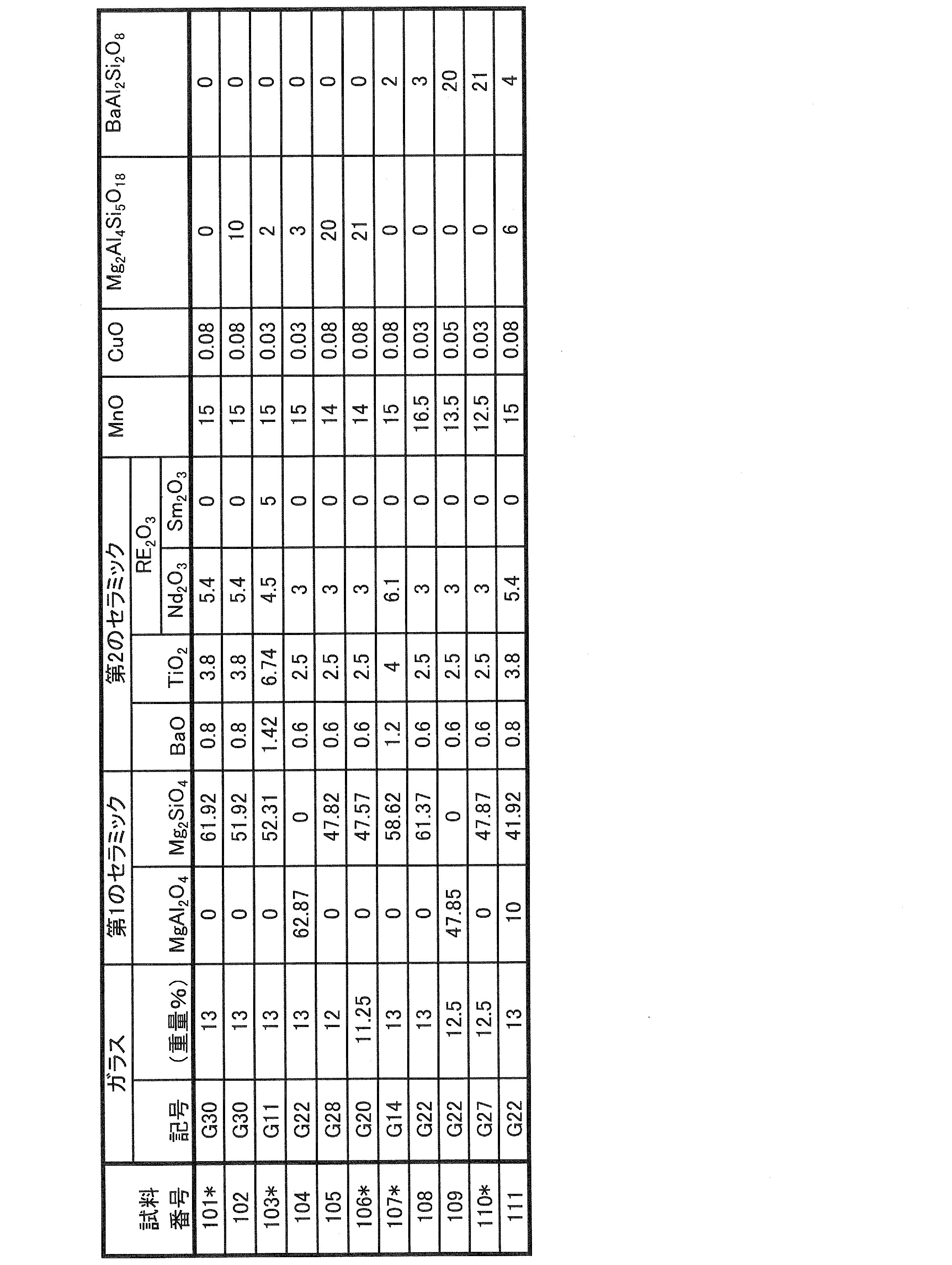
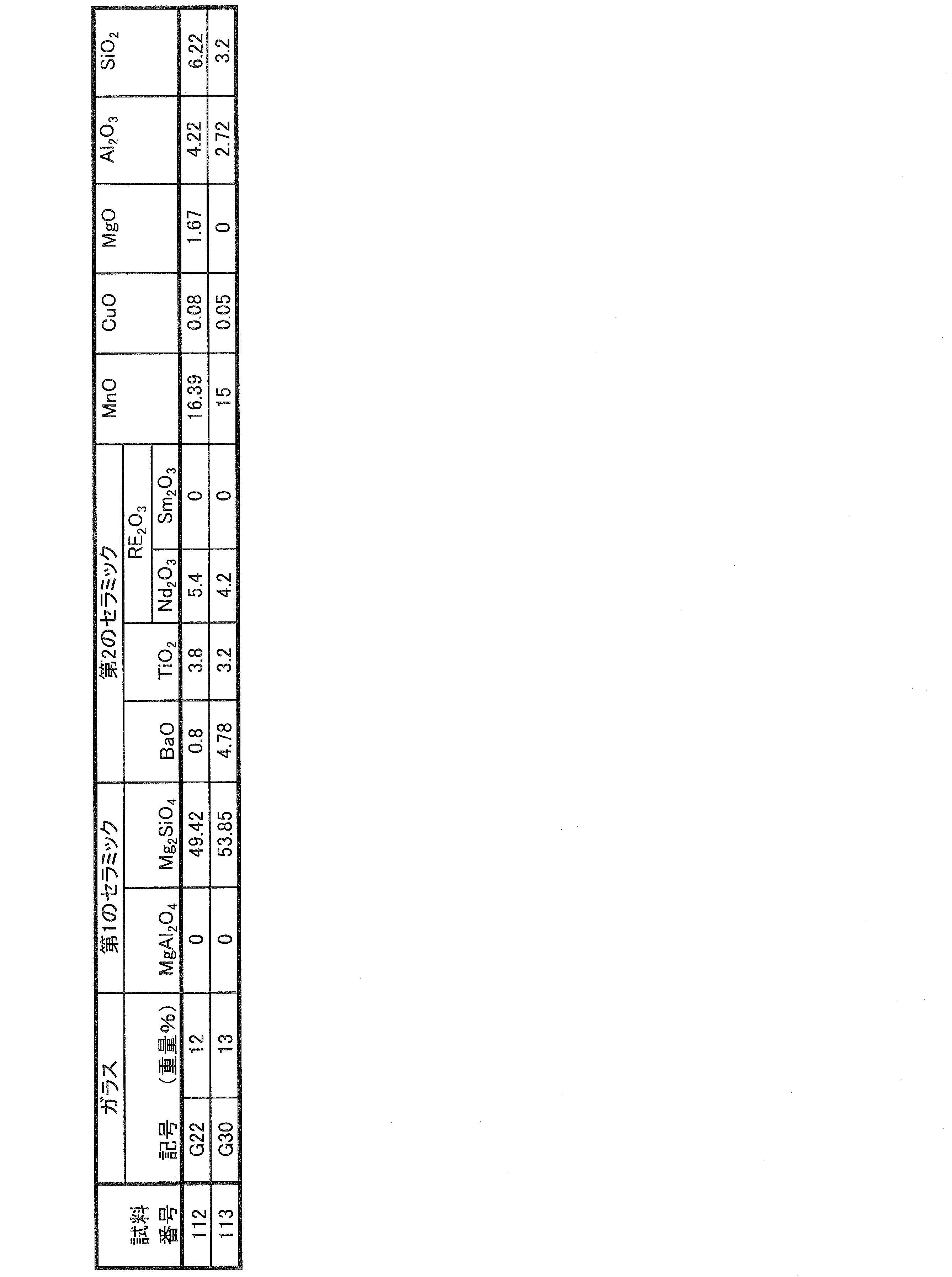
以後、実験例1の場合と同様の要領で、試料を作製し、表8に示すように、比誘電率(εr)、Qf、静電容量温度係数(β)および絶縁信頼性を評価した。この実験例では、εrが8以下というように、εrがより低い誘電体材料を得ることを目的とした。なお、βについては、より厳しく、絶対値で100ppm/K以上のものを不合格と判定した。
なお、表8の「備考」欄には、この実験例において不合格となった試料についての不合格理由が簡潔に記載されている。
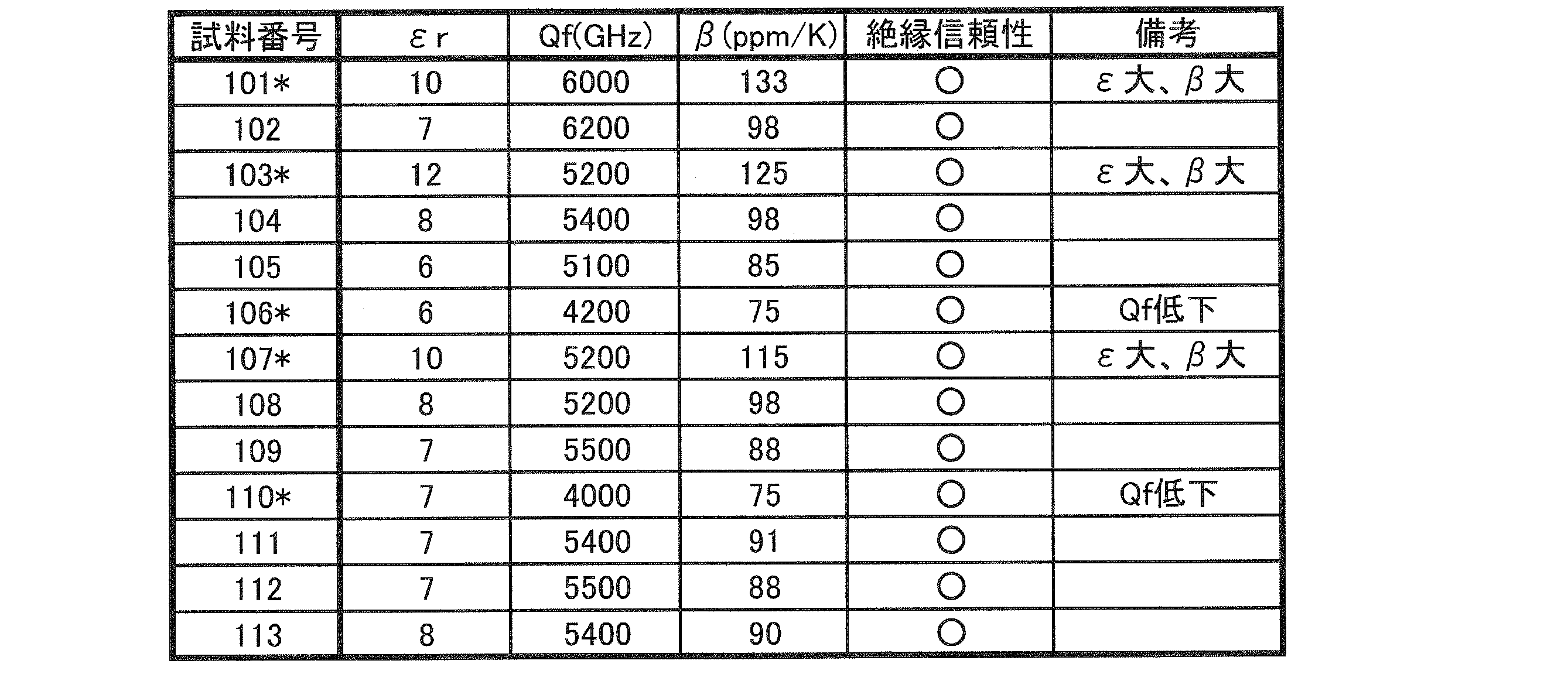
表8において、この実験例で不合格と判定された試料については、その試料番号に*が付されている。
表6ないし表8から、以下のことがわかる。
Mg2Al4Si5O18およびBaAl2Si2O8の少なくとも一方を3.0重量%以上含む試料102、104~106、および108~113と、そうではない試料101、103および107との比較から、前者によれば、8以下といった、より低いεrが得られ、また、静電容量温度係数βが絶対値で100ppm/K未満となった。
また、試料112および113からわかるように、Mg2Al4Si5O18およびBaAl2Si2O8のような複合酸化物は、その素材となる単体酸化物を添加しても同様の効果が得られた。
他方、Mg2Al4Si5O18およびBaAl2Si2O8の少なくとも一方を20.0重量%より多く含む試料106および110では、Qfの低下が見られた。
[実験例3]
実験例3では、高誘電率セラミック層のためのガラスセラミック単体での評価を行なった。
実験例3では、高誘電率セラミック層のためのガラスセラミック単体での評価を行なった。
実験例1の場合と同様にして、第1のセラミックとしてのスピネル化合物:MgAl2O4およびフォルステライト化合物:Mg2SiO4、第2のセラミックとなるBaO、TiO2、およびRE2O3としてのNd2O3、MnO、ならびにCuOの各粉末を用意した。
次に、表9および表10に示す組成となるように、表1に示したガラス、MgAl2O4、Mg2SiO4、BaO、TiO2、Nd2O3、MnO、およびCuOの各粉末を調合し、混合した後、有機溶剤およびバインダを加えて、スラリーを作製した。


以後、実験例1の場合と同様の要領で、試料を作製し、表11および表12に示すように、比誘電率(εr)、Qf、静電容量温度係数(β)および絶縁信頼性を評価した。この実験例では、εrが30以上の誘電体材料を得ることを目的とした。Qfについては、5000GHz未満のものを不合格と判定し、βについては、絶対値で150ppm/Kを超えるものを不合格と判定した。
なお、十分に焼結しなかった試料については、表11および表12の「備考」欄に「未焼結」と表示し、また、ガラスがガラス化しなかった試料については、「備考」欄に「ガラス化しない」と表示し、これらの試料では、εr、Qf、βおよび絶縁信頼性の各評価を行なわなかった。また、「備考」欄には、この実験例において不合格となった試料についての不合格理由が簡潔に記載されている。
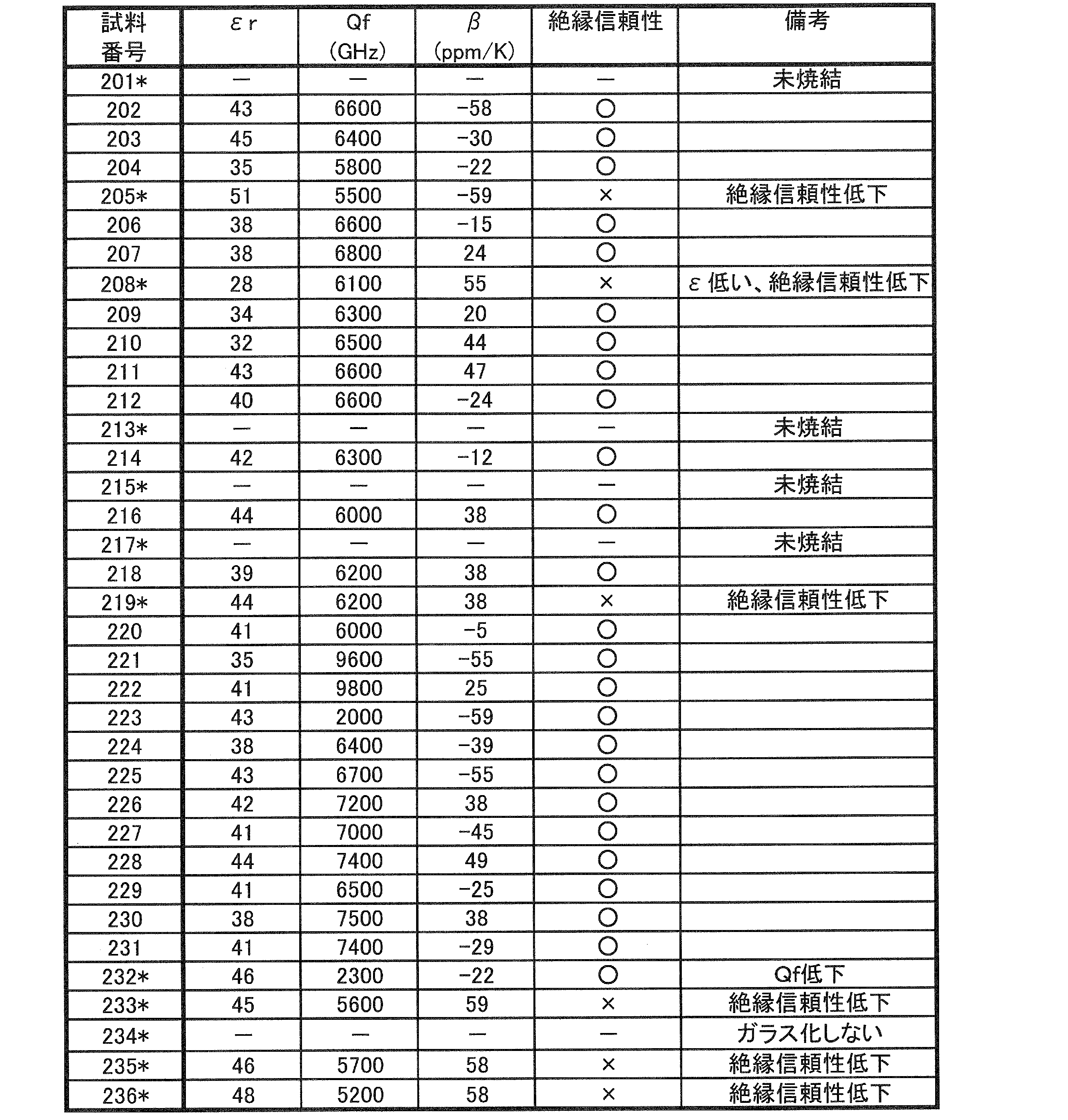

表11おい表12において、この実験例で不合格と判定された試料については、その試料番号に*が付されている。
表9ないし表12から、以下のことがわかる。
まず、表9および表11に示した試料201~236について考察する。試料201~236では、表1に示したガラスG1~G36のすべてについて、そのいずれかが用いられた。なお、「ガラス」の含有量については、試料201~236のすべてにおいて、「9重量%」と一定とした。
試料201では、十分に焼結しなかった。これは、Li2O含有量が0.3重量%より少ないガラスG1を用いたためであると推測される。
試料205では、絶縁信頼性が低下した。これは、Li2O含有量が7.5重量%より多いガラスG5を用いたためであると推測される。
試料208では、εrが低く、絶縁信頼性が低下した。これは、アルカリ土類金属含有量が44.0重量%より少ないガラスG8を用いたためであると推測される。
試料213では、十分に焼結しなかった。これは、アルカリ土類金属含有量が69.0重量%より多いガラスG13を用いたためであると推測される。
試料215では、十分に焼結しなかった。これは、B2O3含有量が10.0重量%より少ないガラスG15を用いたためであると推測される。
試料217では、十分に焼結しなかった。これは、SiO2含有量が30.0重量%より多いガラスG17を用いたためであると推測される。
試料219では、絶縁信頼性が低下した。これは、B2O3含有量が20.0重量%より多いガラスG19を用いたためであると推測される。
試料232では、Qfが低下した。これは、MgO含有量が0.1重量%より少ないガラスG32を用いたためであると推測される。
試料233では、絶縁信頼性が低下した。これは、MgO含有量が5.5重量%より多いガラスG33を用いたためであると推測される。
試料234では、ガラス化しなかった。これは、SiO2含有量が14.2重量%より少ないガラスG34を用いたためであると推測される。
試料235では、絶縁信頼性が低下した。これは、Al2O3含有量が0.5重量%より少ないガラスG35を用いたためであると推測される。
試料236では、絶縁信頼性が低下した。これは、Al2O3含有量が4.0重量%より多いガラスG36を用いたためであると推測される。
上記試料201、205、208、213、215、217、219、および232~236以外の表9および表11に示した試料202~204、206、207、209~212、214、216、218、および220~231では、εrが30以上であり、また、Qf、βおよび絶縁信頼性において良好な結果を示した。
これは、アルカリ土類金属含有量が44.0~69.0重量%、SiO2含有量が14.2~30.0重量%、B2O3含有量が10.0~20.0重量%、Al2O3含有量が0.5~4.0重量%、Li2O含有量が0.3~7.5重量%、およびMgO含有量が0.1~5.5重量%であるという条件を満たすガラスG2、G3、G4、G6、G7、G9、G10、G11、G12、G14、G16、G18、G20、G21、G22、G23、G24、G25、G26、G27、G28、G29、G30、およびG31のいずれかを用いたためであると推測される。
次に、表10および表12に示した試料237~273について考察する。試料237~273では、「ガラス」として表1に示したガラスG22を用いながら、「ガラス」、「第1のセラミック」、「第2のセラミック」、「MnO」、および「CuO」の各含有量を変更した。
試料237では、絶縁信頼性が低下した。これは、第2のセラミックにおけるBaO含有量が15.7重量%より多かったためであると推測される。
試料238では、εrが30未満となった。これは、第2のセラミックにおけるBaO含有量が2.5重量%より少なかったためであると推測される。
試料240では、絶縁信頼性が低下した。これは、第2のセラミックにおけるTiO2含有量が11.2重量%より少なかったためであると推測される。
試料243では、εrが30未満となった。これは、第2のセラミックにおけるTiO2含有量が36.4重量%より多かったためであると推測される。
試料245では、十分に焼結しなかった。これは、第2のセラミックにおけるRE2O3としてのNd2O3含有量が65.3重量%より多かったためであると推測される。
試料249では、εrが30未満となった。これは、第2のセラミックにおけるRE2O3としてのNd2O3含有量が24.6重量%より少なかったためであると推測される。
試料250では、十分に焼結しなかった。これは、ガラス含有量が3重量%より少なかったためであると推測される。
試料255では、絶縁信頼性が低下した。これは、ガラス含有量が15重量%より多かったためであると推測される。
試料256および試料260では、静電容量温度係数βが悪化した。これは、第1のセラミックとしてのMgAl2O4またはMg2SiO4の含有量が15重量%より多かったためであると推測される。
試料259および試料263では、静電容量温度係数βが悪化した。これは、第1のセラミックとしてのMgAl2O4またはMg2SiO4の含有量が1重量%より少なかったためであると推測される。
試料264では、絶縁信頼性が低下した。これは、MnO含有量が2.3重量%より少なかったためであると推測される。
試料266では、Qfが低下した。これは、MnO含有量が10重量%より多かったためであると推測される。
試料270では、絶縁信頼性が低下した。これは、CuO含有量が1.2重量%より多かったためであると推測される。
上記試料237、238、240、243、245、249、250、255、256、259、260、263、264、266および270以外の表10および表12に示した試料239、241、242、244、246~248、251~254、257、258、261、262、265、267~269、および271~273では、Qf、βおよび絶縁信頼性において良好な結果を示した。
これは、第1のセラミック含有量が1~15重量%、ガラス含有量が3~15重量%、MnO含有量が2.3~10重量%、BaO含有量が2.5~15.7重量%、RE2O3含有量が24.6~65.3重量%、TiO2含有量が11.2~36.4重量%、および、CuO含有量が1.2重量%以下であるという条件を満たしたためであると推測される。
なお、実験例3では、第2のセラミックにおけるRE2O3として、Nd2O3を用いたが、Sm2O3をはじめ、他の希土類元素を用いた場合も同様の傾向を示すことが確認されている。
[実験例4]
実験例4では、低誘電率セラミック層と高誘電率セラミック層との各々について、これらが共焼結体とされた場合の特性への影響、特に、比誘電率εrおよび静電容量温度係数βへの影響について調査した。図6(A)および同(B)には、それぞれ、この実験例において作製した2種類の共焼結体71および72が断面図で示されている。
実験例4では、低誘電率セラミック層と高誘電率セラミック層との各々について、これらが共焼結体とされた場合の特性への影響、特に、比誘電率εrおよび静電容量温度係数βへの影響について調査した。図6(A)および同(B)には、それぞれ、この実験例において作製した2種類の共焼結体71および72が断面図で示されている。
図6(A)に示した共焼結体71は、厚み10μmの低誘電率セラミック層73を、厚み0.5mmの2つの高誘電率セラミック層74および75で挟んだ構造を有するものとした。低誘電率セラミック層73と高誘電率セラミック層74および75との各間には、それぞれ、内部電極76および77が一部において互いに対向するように形成され、相対向する端面上には、内部電極76および77にそれぞれ電気的に接続される外部電極78および79が形成された。この内部電極間距離は10μm、電極面積は4mm□であった。
図6(B)に示した共焼結体72は、図6(A)に示した共焼結体71とは低誘電率セラミック層と高誘電率セラミック層との位置関係が逆であり、厚み10μmの高誘電率セラミック層80を、厚み0.5mmの2つの低誘電率セラミック層81および82で挟んだ構造を有するものとした。高誘電率セラミック層80と低誘電率セラミック層81および82との各間には、それぞれ、内部電極83および84が一部において互いに対向するように形成され、相対向する端面上には、内部電極83および84にそれぞれ電気的に接続される外部電極85および86が形成された。
上記共焼結体71および72において、平面寸法は10mm×10mmとした。また、内部電極76、77、83および84ならびに外部電極78、79、85および86はCuを導電成分とする導電性ペーストの印刷により形成した。
前述した実験例1および2において作製した低誘電率ガラスセラミックの、共焼結体とされたときの特性を評価する場合には、図6(A)に示した共焼結体71を用い、実験例3において作製した高誘電率ガラスセラミックの、共焼結体とされたときの特性を評価する場合には、図6(B)に示した共焼結体72を用いた。
共焼結体71中の低誘電率セラミック層73および共焼結体72中の高誘電率セラミック層80の各々について、比誘電率εrおよび静電容量温度係数βを求めたところ、低誘電率ガラスセラミック単体および高誘電率ガラスセラミック単体の各場合と同等の結果が得られた。
より具体的には、比誘電率εrは、LCRメータにより、1MHzでの静電容量値を測定し、その値と対向電極の面積と距離から、以下の式により求めた。
εr=(d×Cap)/(ε0×S)
ここで、dは電極間距離[m]、Sは対向電極面積[m2]、Capは静電容量[F]、ε0は真空の誘電率(8.854×10⁻¹²[F/])である。
εr=(d×Cap)/(ε0×S)
ここで、dは電極間距離[m]、Sは対向電極面積[m2]、Capは静電容量[F]、ε0は真空の誘電率(8.854×10⁻¹²[F/])である。
また、静電容量温度係数βは実験例1の場合と同様の方法により求めた。
なお、Qfについては特に評価しなかったが、上記のように、比誘電率εrおよび静電容量温度係数βが同等であることから、Qfについても単体の場合と同等であると推測される。
[実験例5]
実験例5では、低誘電率セラミック層と高誘電率セラミック層との共焼結体において、低誘電率セラミック層に含まれるガラスの含有量GLと高誘電率セラミック層に含まれるガラスの含有量GHとの比率GL/GH、ならびに、低誘電率セラミック層に含まれるMnOの含有量MLと高誘電率セラミック層に含まれるMnOの含有量MHとの比率ML/MHについての好ましい範囲が存在するのか、もし存在するとすれば、どの範囲が好ましいのか、を調査するための実験を実施した。
実験例5では、低誘電率セラミック層と高誘電率セラミック層との共焼結体において、低誘電率セラミック層に含まれるガラスの含有量GLと高誘電率セラミック層に含まれるガラスの含有量GHとの比率GL/GH、ならびに、低誘電率セラミック層に含まれるMnOの含有量MLと高誘電率セラミック層に含まれるMnOの含有量MHとの比率ML/MHについての好ましい範囲が存在するのか、もし存在するとすれば、どの範囲が好ましいのか、を調査するための実験を実施した。
上記比率GL/GHおよび比率ML/MHを種々に異ならせた試料を得るため、表13の「低誘電率層試料番号」の欄に示した試料番号が付された表3に示した低誘電率ガラスセラミックと、表13の「高誘電率試料番号」の欄に示した試料番号が付された表10に示した高誘電率ガラスセラミックとを組み合わせて、図6(A)および(B)にそれぞれ示すような共焼結体71および72を作製した。
表13の「GL/GH」および「ML/MH」の各欄には、組み合わされた低誘電率ガラスセラミックと高誘電率ガラスセラミックとについての上記比率GL/GHおよび上記比率ML/MHがそれぞれ示されている。
この実験例では、図6(A)に示した共焼結体71を用いて、低誘電率ガラスセラミックの絶縁信頼性を評価するとともに、図6(B)に示した共焼結体72を用いて、高誘電率ガラスセラミックの絶縁信頼性を評価した。
絶縁信頼性の評価のため、150℃の温度下で、共焼結体71の外部電極78および79間または共焼結体72の外部電極85および86間に、DC200V、100Vおよび50Vの各電圧を100時間印加する試験を実施した。試験後において絶縁抵抗を測定し、この試験後のlog (IR[Ω])が11未満となった場合は、不合格と判定した。
表13の「低誘電率側信頼性」の欄には、低誘電率セラミック層側の絶縁信頼性が示され、「高誘電率側信頼性」の欄には、高誘電率セラミック層側の絶縁信頼性が示されているが、印加電圧が200Vでも絶縁抵抗が劣化しなかった場合を「◎」で表示し、200Vでは劣化したが100Vでは劣化しなかった場合を「○」で表示し、200Vおよび100Vでは劣化したが50Vで劣化した場合を「△」で表示している。

表13において、まず、「GL/GH」に注目すると、1.0≦GL/GH≦2.0の条件を満たす試料302~304および311~316では、特に「低誘電率側信頼性」に関して、「○」または「◎」の評価が得られた。
次に、「ML/MH」に注目すると、1.5≦ML/MH≦3.6の条件を満たす試料301、303、304、307~309および311~316では、特に「高誘電率側信頼性」に関して、「○」または「◎」の評価が得られた。
さらに、1.0≦GL/GH≦2.0の条件および1.5≦ML/MH≦3.6の条件の双方を満たす試料311~316では、「低誘電率側信頼性」および「高誘電率側信頼性」の双方に関して、「◎」の評価が得られた。
[実験例6]
実験例6では、実験例5の場合と同様、共焼結体におけるガラスの含有量の比率GL/GHおよびMnOの含有量の比率ML/MHが、絶縁信頼性に及ぼす影響を調査するとともに、低誘電率セラミック層が、さらに、Mg2Al4Si5O18およびBaAl2Si2O8の少なくとも一方を含む場合の反り抑制効果を調査した。
実験例6では、実験例5の場合と同様、共焼結体におけるガラスの含有量の比率GL/GHおよびMnOの含有量の比率ML/MHが、絶縁信頼性に及ぼす影響を調査するとともに、低誘電率セラミック層が、さらに、Mg2Al4Si5O18およびBaAl2Si2O8の少なくとも一方を含む場合の反り抑制効果を調査した。
前述した実験例2でも、低誘電率ガラスセラミックに対する、Mg2Al4Si5O18およびBaAl2Si2O8の少なくとも一方の添加による影響を調査した。その結果、比誘電率(εr)をより低くすることができ、また、静電容量温度係数(β)も改善されることを見出した。
この実験例6では、実験例2における表6および表7に示した試料101~113とは異なる、以下の表14に示すような組成の試料401~413を、実験例2の場合と同様の方法により作製した。
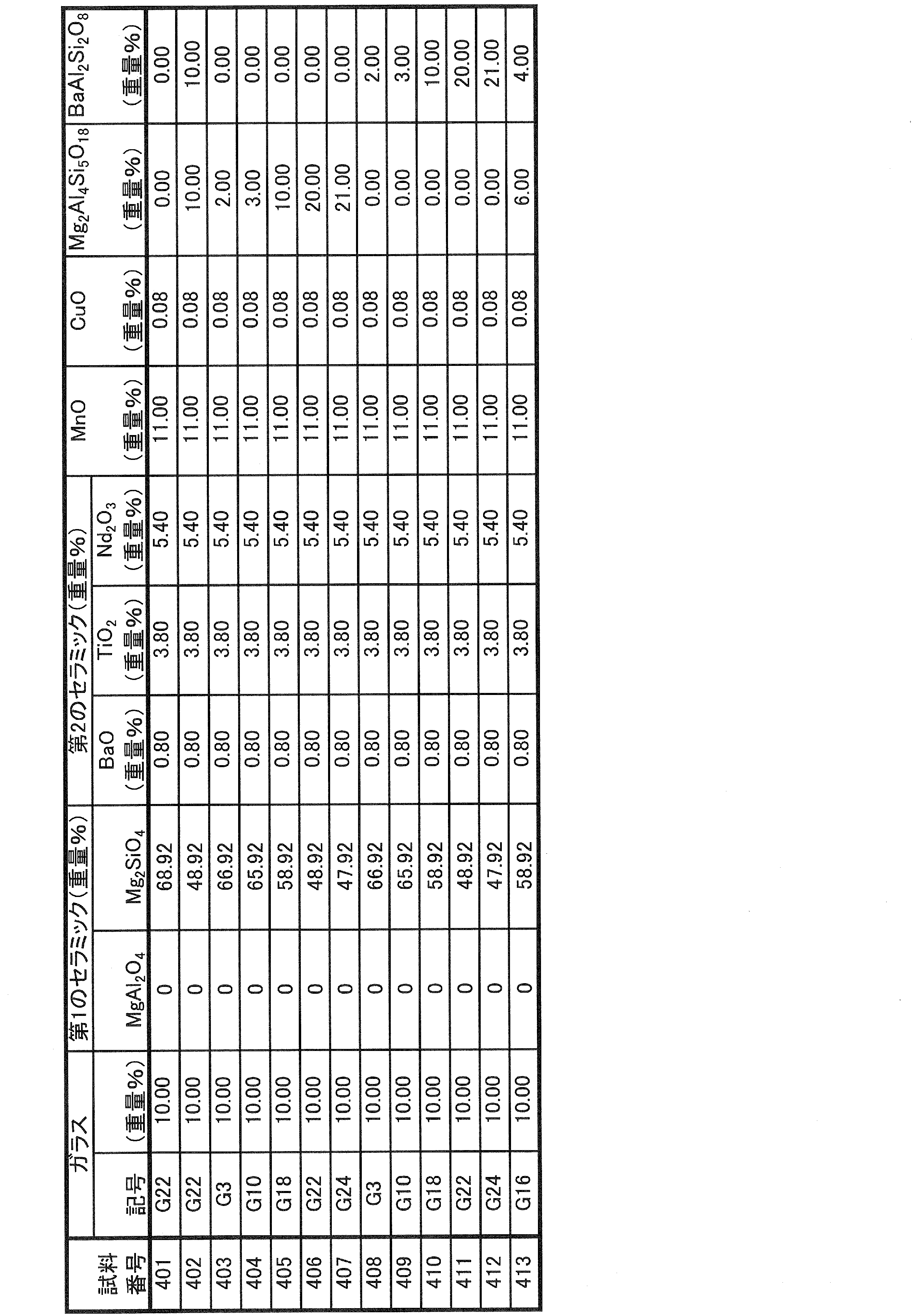
次いで、実験例2の場合と同様の要領により、試料101~113の各々に係る低誘電率ガラスセラミック単独での特性を評価した。その結果が表15に示されている。

表15において、前述した実験例2の場合と同様の傾向が現れている。
すなわち、Mg2Al4Si5O18およびBaAl2Si2O8の少なくとも一方を3.0重量%以上含む試料402、404~407および409~413と、そうではない試料401、403および408との比較から、前者によれば、8以下といった、より低いεrが得られ、また、静電容量温度係数βが絶対値で100ppm/K未満となった。
他方、Mg2Al4Si5O18およびBaAl2Si2O8の少なくとも一方を20.0重量%より多く含む試料407および412では、Qfの低下が見られた。
次に、表14に示した低誘電率ガラスセラミックと前掲の表10に示した高誘電率ガラスセラミックとを、表16に示すように、実験例5の場合と同様の要領で組み合わせて、ガラスの含有率の比率GL/GHおよびMnOの含有率の比率ML/MHを種々に異ならせた試料501~513に係る共焼結体を得た。
次に、実験例5の場合と同様の要領にて、表16に示すように、「低誘電率側信頼性」および「高誘電率側信頼性」を評価した。
この実験例6では、さらに、表16に示すように、「反り」を評価した。「反り」は、厚み0.5mmの低誘電率セラミック層と厚み0.5mmの高誘電率セラミック層とが積層された、平面寸法が50mm×50mmで厚みが1mmの複合基板を作製し、これを定盤に載せ、最高点高さを測定し、これから複合基板の厚みを差し引いた値を反り量として求めた。反り量が0.1mm以下となったものを合格と判定し、表16の「反り」の欄に「○」と表示し、反り量が0.1mmを超えたものを不合格と判定し、同欄に「×」と表示した。
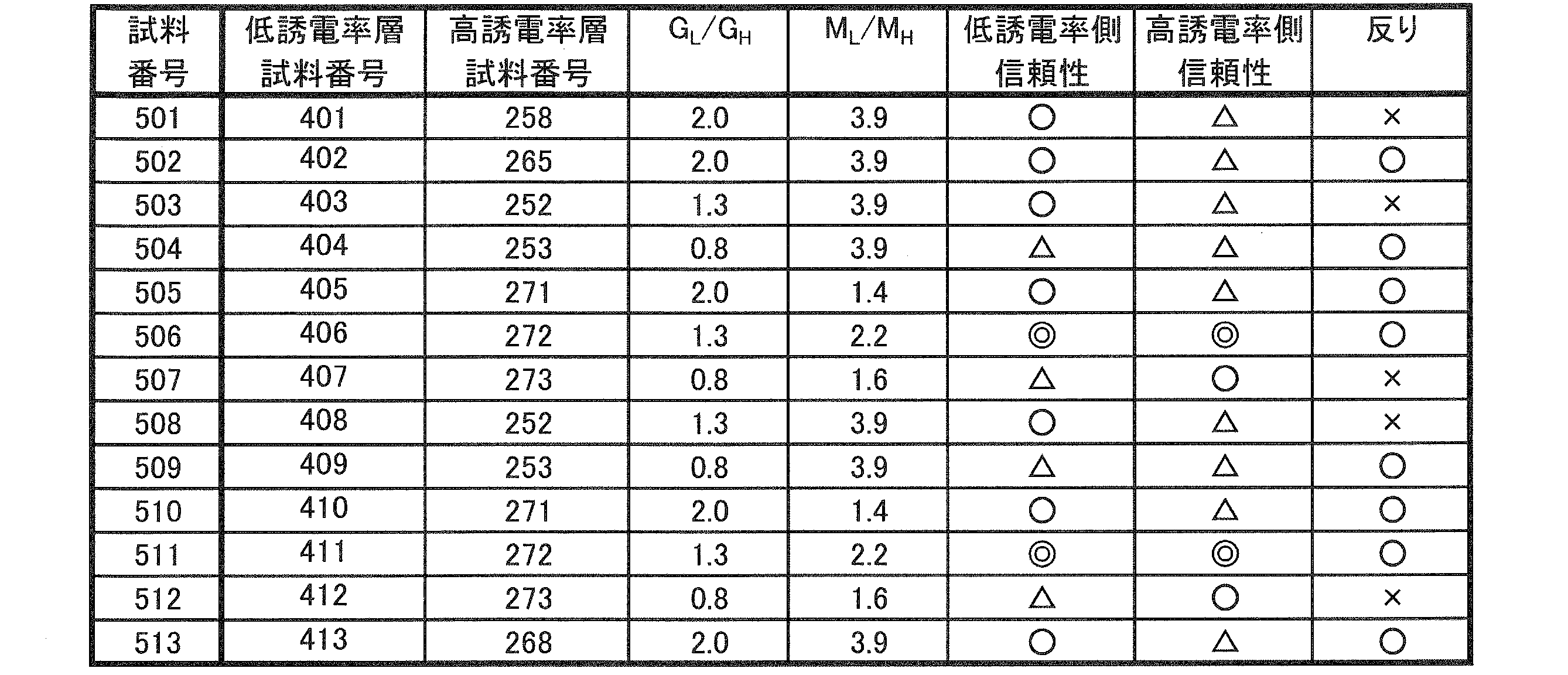
表16の「低誘電率側信頼性」および「高誘電率側信頼性」に関しては、実験例5の場合と同様の傾向が現れている。
すなわち、表16において、まず、「GL/GH」に注目すると、1.0≦GL/GH≦2.0の条件を満たす試料501~503、505、506、508、510、511および513では、特に「低誘電率側信頼性」に関して、「○」または「◎」の評価が得られた。
次に、「ML/MH」に注目すると、1.5≦ML/MH≦3.6の条件を満たす試料506、507、511および512では、特に「高誘電率側信頼性」に関して、「○」または「◎」の評価が得られた。
さらに、1.0≦GL/GH≦2.0の条件および1.5≦ML/MH≦3.6の条件の双方を満たす試料506および511では、「低誘電率側信頼性」および「高誘電率側信頼性」の双方に関して、「◎」の評価が得られた。
次に、「反り」について見ると、「低誘電率層」において、さらに、Mg2Al2Si5O15およびBaAl2Si2O8の少なくとも一方を3.0~20.0重量%含む表14の試料402、404~406、409~411および413に係る低誘電率ガラスセラミックを用いた試料502、504~506、509~511および513では、「○」の評価が得られた。
1 セラミック多層モジュール
2 多層セラミック基板
3,73,81,82 低誘電率セラミック層
4,74,75,80 高誘電率セラミック層
21 LCフィルタ
23 部品本体
28~32,35~40 低誘電率セラミック層
33,34 高誘電率セラミック層
71,72 共焼結体
2 多層セラミック基板
3,73,81,82 低誘電率セラミック層
4,74,75,80 高誘電率セラミック層
21 LCフィルタ
23 部品本体
28~32,35~40 低誘電率セラミック層
33,34 高誘電率セラミック層
71,72 共焼結体
Claims (7)
- 積層された低誘電率セラミック層と高誘電率セラミック層とを備える、複合積層セラミック電子部品であって、
前記低誘電率セラミック層と前記高誘電率セラミック層とは、いずれも、
(1)MgAl2O4およびMg2SiO4の少なくとも一方からなる第1のセラミックと、
(2)BaO、RE2O3(REは希土類元素)およびTiO2からなる第2のセラミックと、
(3)RO(RはBa、CaおよびSrから選ばれる少なくとも1種のアルカリ土類金属)を44.0~69.0重量%、SiO2を14.2~30.0重量%、B2O3を10.0~20.0重量%、Al2O3を0.5~4.0重量%、Li2Oを0.3~7.5重量%、およびMgOを0.1~5.5重量%それぞれ含むガラスと、
(4)MnOと
を含む、ガラスセラミックからなり、
前記低誘電率セラミック層は、
前記第1のセラミックを47.55~69.32重量%含み、
前記ガラスを6~20重量%含み、
前記MnOを7.5~18.5重量%含み、
前記第2のセラミックとして、BaOを0.38~1.43重量%、RE2O3を1.33~9.5重量%、およびTiO2を0.95~6.75重量%それぞれ含み、
比誘電率が15以下であり、
前記高誘電率セラミック層は、
前記第1のセラミックを1~15重量%含み、
前記ガラスを3~15重量%含み、
前記MnOを2.3~10重量%含み、
前記第2のセラミックとして、BaOを2.5~15.7重量%、RE2O3を24.6~65.3重量%、およびTiO2を11.2~36.4重量%それぞれ含み、
比誘電率が30以上である、
複合積層セラミック電子部品。 - 前記低誘電率セラミック層に含まれる前記ガラスの含有量GLおよび前記高誘電率セラミック層に含まれる前記ガラスの含有量GHは、1.0≦GL/GH≦2.0の条件を満たす、請求項1に記載の複合積層セラミック電子部品。
- 前記低誘電率セラミック層に含まれる前記MnOの含有量MLおよび前記高誘電率セラミック層に含まれる前記MnOの含有量MHは、1.5≦ML/MH≦3.6の条件を満たす、請求項1に記載の複合積層セラミック電子部品。
- 前記低誘電率セラミック層に含まれる前記ガラスの含有量GLおよび前記高誘電率セラミック層に含まれる前記ガラスの含有量GHは、1.0≦GL/GH≦2.0の条件を満たすとともに、
前記低誘電率セラミック層に含まれる前記MnOの含有量MLおよび前記高誘電率セラミック層に含まれる前記MnOの含有量MHは、1.5≦ML/MH≦3.6の条件を満たす、
請求項1に記載の複合積層セラミック電子部品。 - 前記低誘電率セラミック層は、さらに、Mg2Al4Si5O18およびBaAl2Si2O8の少なくとも一方を3.0~20.0重量%含む、請求項1ないし4のいずれかに記載の複合積層セラミック電子部品。
- 前記低誘電率セラミック層は、さらに、CuOを0.23重量%以下含む、請求項1ないし5のいずれかに記載の複合積層セラミック電子部品。
- 前記高誘電率セラミック層は、さらに、CuOを1.2重量%以下含む、請求項1ないし6のいずれかに記載の複合積層セラミック電子部品。
Priority Applications (3)
| Application Number | Priority Date | Filing Date | Title |
|---|---|---|---|
| CN201280024128.0A CN103548102B (zh) | 2011-05-19 | 2012-02-13 | 复合层叠陶瓷电子部件 |
| JP2013515015A JP5435176B2 (ja) | 2011-05-19 | 2012-02-13 | 複合積層セラミック電子部品 |
| US14/067,286 US9067380B2 (en) | 2011-05-19 | 2013-10-30 | Composite laminate ceramic electronic component |
Applications Claiming Priority (2)
| Application Number | Priority Date | Filing Date | Title |
|---|---|---|---|
| JP2011112127 | 2011-05-19 | ||
| JP2011-112127 | 2011-05-19 |
Related Child Applications (1)
| Application Number | Title | Priority Date | Filing Date |
|---|---|---|---|
| US14/067,286 Continuation US9067380B2 (en) | 2011-05-19 | 2013-10-30 | Composite laminate ceramic electronic component |
Publications (1)
| Publication Number | Publication Date |
|---|---|
| WO2012157300A1 true WO2012157300A1 (ja) | 2012-11-22 |
Family
ID=47176642
Family Applications (1)
| Application Number | Title | Priority Date | Filing Date |
|---|---|---|---|
| PCT/JP2012/053260 Ceased WO2012157300A1 (ja) | 2011-05-19 | 2012-02-13 | 複合積層セラミック電子部品 |
Country Status (4)
| Country | Link |
|---|---|
| US (1) | US9067380B2 (ja) |
| JP (1) | JP5435176B2 (ja) |
| CN (1) | CN103548102B (ja) |
| WO (1) | WO2012157300A1 (ja) |
Cited By (7)
| Publication number | Priority date | Publication date | Assignee | Title |
|---|---|---|---|---|
| JPWO2012157299A1 (ja) * | 2011-05-19 | 2014-07-31 | 株式会社村田製作所 | ガラスセラミック組成物 |
| US20150030830A1 (en) * | 2012-02-13 | 2015-01-29 | Murata Manufacturing Co., Ltd. | Composite Laminated Ceramic Electronic Component |
| WO2015033704A1 (ja) * | 2013-09-05 | 2015-03-12 | 株式会社村田製作所 | コンデンサ内蔵電子部品 |
| WO2017122382A1 (ja) * | 2016-01-13 | 2017-07-20 | 株式会社村田製作所 | ガラスセラミック焼結体、ガラスセラミック組成物、積層セラミックコンデンサ及び積層セラミックコンデンサの製造方法 |
| JP2019059660A (ja) * | 2017-09-26 | 2019-04-18 | Tdk株式会社 | 誘電体磁器組成物および電子部品 |
| WO2021187113A1 (ja) * | 2020-03-19 | 2021-09-23 | ローム株式会社 | 積層型コンデンサ |
| US12281024B1 (en) | 2024-11-20 | 2025-04-22 | Imam Mohammad Ibn Saud Islamic University | Copper oxide-magnesium (CuO.MgAl2O4) spinel nanocomposite and method of synthesis thereof |
Families Citing this family (7)
| Publication number | Priority date | Publication date | Assignee | Title |
|---|---|---|---|---|
| JP5888524B2 (ja) * | 2012-02-13 | 2016-03-22 | 株式会社村田製作所 | 複合積層セラミック電子部品 |
| US10236123B2 (en) * | 2015-07-19 | 2019-03-19 | Vq Research, Inc. | Methods and systems to minimize delamination of multilayer ceramic capacitors |
| US10669207B2 (en) * | 2017-09-26 | 2020-06-02 | Tdk Corporation | Dielectric ceramic composition and electronic component |
| JP7122118B2 (ja) * | 2018-01-24 | 2022-08-19 | 太陽誘電株式会社 | セラミックコンデンサおよびその製造方法 |
| JP7037945B2 (ja) * | 2018-01-26 | 2022-03-17 | 太陽誘電株式会社 | セラミックコンデンサおよびその製造方法 |
| JP7021552B2 (ja) * | 2018-02-09 | 2022-02-17 | Tdk株式会社 | 誘電体フィルタ |
| CN115784718B (zh) * | 2022-11-29 | 2024-03-26 | 西安创联电气科技(集团)有限责任公司 | 一种微波介质陶瓷瓷粉及其制备方法 |
Citations (4)
| Publication number | Priority date | Publication date | Assignee | Title |
|---|---|---|---|---|
| JP2002104870A (ja) * | 2000-09-28 | 2002-04-10 | Kyocera Corp | 誘電体磁器および積層体 |
| JP2003063861A (ja) * | 2000-12-19 | 2003-03-05 | Murata Mfg Co Ltd | 複合積層セラミック電子部品及びその製造方法 |
| JP2006124270A (ja) * | 2004-09-30 | 2006-05-18 | Tdk Corp | 誘電体磁器組成物及びその製造方法 |
| JP2010235327A (ja) * | 2009-03-30 | 2010-10-21 | Tdk Corp | 誘電体磁器組成物 |
Family Cites Families (22)
| Publication number | Priority date | Publication date | Assignee | Title |
|---|---|---|---|---|
| JP2000143341A (ja) * | 1998-09-11 | 2000-05-23 | Murata Mfg Co Ltd | 誘電体セラミック組成物及び積層セラミック部品 |
| JP3680715B2 (ja) | 2000-07-21 | 2005-08-10 | 株式会社村田製作所 | 絶縁体磁器組成物 |
| GB2365007B (en) * | 2000-07-21 | 2002-06-26 | Murata Manufacturing Co | Insulative ceramic compact |
| GB2371775B (en) * | 2000-12-19 | 2002-12-31 | Murata Manufacturing Co | Composite multilayer ceramic electronic parts and method of manfacturing the same |
| KR100444222B1 (ko) * | 2001-11-13 | 2004-08-16 | 삼성전기주식회사 | 유전체 세라믹 조성물 |
| JP4283694B2 (ja) * | 2004-01-30 | 2009-06-24 | シーケーディ株式会社 | 流量調整システム |
| US7351674B2 (en) * | 2004-03-01 | 2008-04-01 | Murata Manufacturing Co., Ltd. | Insulating ceramic composition, insulating ceramic sintered body, and mulitlayer ceramic electronic component |
| US7368408B2 (en) * | 2004-03-01 | 2008-05-06 | Murata Manufacturing Co., Ltd. | Glass-ceramic composition, glass-ceramic sintered body, and monolithic ceramic electronic component |
| JP2006173422A (ja) * | 2004-12-17 | 2006-06-29 | Murata Mfg Co Ltd | 積層型電子部品およびその製造方法 |
| JP2006261351A (ja) * | 2005-03-16 | 2006-09-28 | Ngk Spark Plug Co Ltd | 積層セラミック部品及びその製造方法 |
| US7517823B2 (en) * | 2005-09-29 | 2009-04-14 | Tdk Corporation | Dielectric porcelain composition and method for production thereof |
| CN101479213B (zh) * | 2006-06-30 | 2012-07-04 | 康宁股份有限公司 | 堇青石铝镁钛酸盐组合物及包含该组合物的陶瓷制品 |
| WO2008018407A1 (en) * | 2006-08-09 | 2008-02-14 | Murata Manufacturing Co., Ltd. | Glass-ceramic composition, sintered glass-ceramic, and laminated ceramic electronic components |
| EP2065346A1 (en) * | 2007-11-30 | 2009-06-03 | Corning Incorporated | High thermal conductivity cordierite glass-ceramic materials |
| US8778819B2 (en) * | 2009-03-26 | 2014-07-15 | Hitachi Metals, Ltd. | Dielectric ceramic composition, multilayer dielectric substrate, electronic component, and method for producing dielectric ceramic composition |
| JP2010235325A (ja) * | 2009-03-30 | 2010-10-21 | Tdk Corp | 誘電体磁器組成物 |
| JP5883217B2 (ja) * | 2009-11-06 | 2016-03-09 | Tdk株式会社 | 六方晶系チタン酸バリウム粉末、その製造方法、誘電体磁器組成物および電子部品 |
| JP5152308B2 (ja) * | 2010-03-09 | 2013-02-27 | Tdk株式会社 | セラミック電子部品 |
| JP5120406B2 (ja) * | 2010-03-31 | 2013-01-16 | Tdk株式会社 | セラミック電子部品及びセラミック電子部品の製造方法 |
| JP5527116B2 (ja) * | 2010-08-31 | 2014-06-18 | Tdk株式会社 | 誘電体磁器組成物および積層型セラミック電子部品 |
| JP2012051750A (ja) * | 2010-08-31 | 2012-03-15 | Tdk Corp | 誘電体磁器組成物の製造方法および積層型セラミック電子部品 |
| JP5761341B2 (ja) * | 2011-05-19 | 2015-08-12 | 株式会社村田製作所 | ガラスセラミック組成物 |
-
2012
- 2012-02-13 WO PCT/JP2012/053260 patent/WO2012157300A1/ja not_active Ceased
- 2012-02-13 CN CN201280024128.0A patent/CN103548102B/zh active Active
- 2012-02-13 JP JP2013515015A patent/JP5435176B2/ja active Active
-
2013
- 2013-10-30 US US14/067,286 patent/US9067380B2/en active Active
Patent Citations (4)
| Publication number | Priority date | Publication date | Assignee | Title |
|---|---|---|---|---|
| JP2002104870A (ja) * | 2000-09-28 | 2002-04-10 | Kyocera Corp | 誘電体磁器および積層体 |
| JP2003063861A (ja) * | 2000-12-19 | 2003-03-05 | Murata Mfg Co Ltd | 複合積層セラミック電子部品及びその製造方法 |
| JP2006124270A (ja) * | 2004-09-30 | 2006-05-18 | Tdk Corp | 誘電体磁器組成物及びその製造方法 |
| JP2010235327A (ja) * | 2009-03-30 | 2010-10-21 | Tdk Corp | 誘電体磁器組成物 |
Cited By (12)
| Publication number | Priority date | Publication date | Assignee | Title |
|---|---|---|---|---|
| JPWO2012157299A1 (ja) * | 2011-05-19 | 2014-07-31 | 株式会社村田製作所 | ガラスセラミック組成物 |
| US9162922B2 (en) | 2011-05-19 | 2015-10-20 | Murata Manufacturing Co., Ltd. | Glass ceramic composition |
| US20150030830A1 (en) * | 2012-02-13 | 2015-01-29 | Murata Manufacturing Co., Ltd. | Composite Laminated Ceramic Electronic Component |
| US9214259B2 (en) * | 2012-02-13 | 2015-12-15 | Murata Manufacturing Co., Ltd. | Composite laminated ceramic electronic component |
| WO2015033704A1 (ja) * | 2013-09-05 | 2015-03-12 | 株式会社村田製作所 | コンデンサ内蔵電子部品 |
| JP5725268B1 (ja) * | 2013-09-05 | 2015-05-27 | 株式会社村田製作所 | コンデンサ内蔵電子部品 |
| US9668353B2 (en) | 2013-09-05 | 2017-05-30 | Murata Manufacturing Co., Ltd. | Electronic component with built-in capacitor |
| WO2017122382A1 (ja) * | 2016-01-13 | 2017-07-20 | 株式会社村田製作所 | ガラスセラミック焼結体、ガラスセラミック組成物、積層セラミックコンデンサ及び積層セラミックコンデンサの製造方法 |
| JPWO2017122382A1 (ja) * | 2016-01-13 | 2018-09-27 | 株式会社村田製作所 | ガラスセラミック焼結体、ガラスセラミック組成物、積層セラミックコンデンサ及び積層セラミックコンデンサの製造方法 |
| JP2019059660A (ja) * | 2017-09-26 | 2019-04-18 | Tdk株式会社 | 誘電体磁器組成物および電子部品 |
| WO2021187113A1 (ja) * | 2020-03-19 | 2021-09-23 | ローム株式会社 | 積層型コンデンサ |
| US12281024B1 (en) | 2024-11-20 | 2025-04-22 | Imam Mohammad Ibn Saud Islamic University | Copper oxide-magnesium (CuO.MgAl2O4) spinel nanocomposite and method of synthesis thereof |
Also Published As
| Publication number | Publication date |
|---|---|
| CN103548102B (zh) | 2016-06-22 |
| JP5435176B2 (ja) | 2014-03-05 |
| US20140057087A1 (en) | 2014-02-27 |
| JPWO2012157300A1 (ja) | 2014-07-31 |
| US9067380B2 (en) | 2015-06-30 |
| CN103548102A (zh) | 2014-01-29 |
Similar Documents
| Publication | Publication Date | Title |
|---|---|---|
| JP5821975B2 (ja) | 複合積層セラミック電子部品 | |
| JP5435176B2 (ja) | 複合積層セラミック電子部品 | |
| JP5761341B2 (ja) | ガラスセラミック組成物 | |
| US8199455B2 (en) | Glass ceramic composition, glass ceramic sintered body, and multilayer ceramic electronic device | |
| US10906839B2 (en) | Low temperature cofired ceramic material, ceramic sintered body, and ceramic electronic component | |
| JP5888524B2 (ja) | 複合積層セラミック電子部品 | |
| US8778502B2 (en) | Glass ceramic composition, glass ceramic sintered body, and monolithic ceramic electronic component | |
| US8592041B2 (en) | Glass ceramic composition and glass ceramic substrate | |
| US8097350B2 (en) | Glass ceramic composition, glass ceramic sintered body, and multilayer ceramic electronic component | |
| JP2009152489A (ja) | セラミック多層部品 | |
| WO2017122381A1 (ja) | 積層体及び電子部品 | |
| JP2004345914A (ja) | 誘電体ガラスセラミック組成物および多層回路基板 |
Legal Events
| Date | Code | Title | Description |
|---|---|---|---|
| 121 | Ep: the epo has been informed by wipo that ep was designated in this application |
Ref document number: 12785286 Country of ref document: EP Kind code of ref document: A1 |
|
| ENP | Entry into the national phase |
Ref document number: 2013515015 Country of ref document: JP Kind code of ref document: A |
|
| NENP | Non-entry into the national phase |
Ref country code: DE |
|
| 122 | Ep: pct application non-entry in european phase |
Ref document number: 12785286 Country of ref document: EP Kind code of ref document: A1 |