WO2012153723A1 - マイクロチップ送液システム - Google Patents
マイクロチップ送液システム Download PDFInfo
- Publication number
- WO2012153723A1 WO2012153723A1 PCT/JP2012/061718 JP2012061718W WO2012153723A1 WO 2012153723 A1 WO2012153723 A1 WO 2012153723A1 JP 2012061718 W JP2012061718 W JP 2012061718W WO 2012153723 A1 WO2012153723 A1 WO 2012153723A1
- Authority
- WO
- WIPO (PCT)
- Prior art keywords
- liquid
- micropump
- liquid feeding
- flow path
- microchip
- Prior art date
- Legal status (The legal status is an assumption and is not a legal conclusion. Google has not performed a legal analysis and makes no representation as to the accuracy of the status listed.)
- Ceased
Links
Images






Classifications
-
- G—PHYSICS
- G01—MEASURING; TESTING
- G01N—INVESTIGATING OR ANALYSING MATERIALS BY DETERMINING THEIR CHEMICAL OR PHYSICAL PROPERTIES
- G01N33/00—Investigating or analysing materials by specific methods not covered by groups G01N1/00 - G01N31/00
- G01N33/48—Biological material, e.g. blood, urine; Haemocytometers
- G01N33/50—Chemical analysis of biological material, e.g. blood, urine; Testing involving biospecific ligand binding methods; Immunological testing
- G01N33/53—Immunoassay; Biospecific binding assay; Materials therefor
- G01N33/543—Immunoassay; Biospecific binding assay; Materials therefor with an insoluble carrier for immobilising immunochemicals
- G01N33/54366—Apparatus specially adapted for solid-phase testing
- G01N33/54373—Apparatus specially adapted for solid-phase testing involving physiochemical end-point determination, e.g. wave-guides, FETS, gratings
-
- B—PERFORMING OPERATIONS; TRANSPORTING
- B01—PHYSICAL OR CHEMICAL PROCESSES OR APPARATUS IN GENERAL
- B01L—CHEMICAL OR PHYSICAL LABORATORY APPARATUS FOR GENERAL USE
- B01L3/00—Containers or dishes for laboratory use, e.g. laboratory glassware; Droppers
- B01L3/50—Containers for the purpose of retaining a material to be analysed, e.g. test tubes
- B01L3/502—Containers for the purpose of retaining a material to be analysed, e.g. test tubes with fluid transport, e.g. in multi-compartment structures
- B01L3/5027—Containers for the purpose of retaining a material to be analysed, e.g. test tubes with fluid transport, e.g. in multi-compartment structures by integrated microfluidic structures, i.e. dimensions of channels and chambers are such that surface tension forces are important, e.g. lab-on-a-chip
- B01L3/502715—Containers for the purpose of retaining a material to be analysed, e.g. test tubes with fluid transport, e.g. in multi-compartment structures by integrated microfluidic structures, i.e. dimensions of channels and chambers are such that surface tension forces are important, e.g. lab-on-a-chip characterised by interfacing components, e.g. fluidic, electrical, optical or mechanical interfaces
-
- B—PERFORMING OPERATIONS; TRANSPORTING
- B01—PHYSICAL OR CHEMICAL PROCESSES OR APPARATUS IN GENERAL
- B01L—CHEMICAL OR PHYSICAL LABORATORY APPARATUS FOR GENERAL USE
- B01L2200/00—Solutions for specific problems relating to chemical or physical laboratory apparatus
- B01L2200/06—Fluid handling related problems
- B01L2200/0605—Metering of fluids
-
- B—PERFORMING OPERATIONS; TRANSPORTING
- B01—PHYSICAL OR CHEMICAL PROCESSES OR APPARATUS IN GENERAL
- B01L—CHEMICAL OR PHYSICAL LABORATORY APPARATUS FOR GENERAL USE
- B01L2300/00—Additional constructional details
- B01L2300/08—Geometry, shape and general structure
- B01L2300/0861—Configuration of multiple channels and/or chambers in a single devices
- B01L2300/0877—Flow chambers
-
- B—PERFORMING OPERATIONS; TRANSPORTING
- B01—PHYSICAL OR CHEMICAL PROCESSES OR APPARATUS IN GENERAL
- B01L—CHEMICAL OR PHYSICAL LABORATORY APPARATUS FOR GENERAL USE
- B01L2400/00—Moving or stopping fluids
- B01L2400/04—Moving fluids with specific forces or mechanical means
- B01L2400/0475—Moving fluids with specific forces or mechanical means specific mechanical means and fluid pressure
- B01L2400/0487—Moving fluids with specific forces or mechanical means specific mechanical means and fluid pressure fluid pressure, pneumatics
-
- G—PHYSICS
- G01—MEASURING; TESTING
- G01N—INVESTIGATING OR ANALYSING MATERIALS BY DETERMINING THEIR CHEMICAL OR PHYSICAL PROPERTIES
- G01N35/00—Automatic analysis not limited to methods or materials provided for in any single one of groups G01N1/00 - G01N33/00; Handling materials therefor
- G01N35/10—Devices for transferring samples or any liquids to, in, or from, the analysis apparatus, e.g. suction devices, injection devices
- G01N2035/1027—General features of the devices
- G01N2035/1048—General features of the devices using the transfer device for another function
- G01N2035/1058—General features of the devices using the transfer device for another function for mixing
- G01N2035/106—General features of the devices using the transfer device for another function for mixing by sucking and blowing
Definitions
- the present invention relates to a microchip liquid feeding system, and more particularly, to a microchip liquid feeding system suitably used for inspection and analysis of biological materials using antigen-antibody reaction.
- a phenomenon that a high light output is obtained by resonating electrons and light in a minute region such as a nanometer level (Surface-Plasmon-Resonance (SPR) phenomenon).
- SPR Surface-Plasmon-Resonance
- a surface plasmon resonance device (hereinafter referred to as an SPR device) that detects minute analytes in a living body can be used.
- SPFS surface plasmon excitation enhanced fluorescence spectroscopy
- SPR surface plasmon resonance
- SPFS device is also one of such specimen detection devices.
- a specimen liquid containing an analyte (antigen) to be detected is prepared in advance, and this is sent to the fine flow path, so that the inside of the fine flow path is obtained.
- the analyte (antigen) is captured by an antibody fixed in a reaction field provided in the above.
- a specimen detection apparatus is usually provided with a microchip liquid feeding system for feeding the specimen liquid into the fine channel.
- FIG. 11 is a schematic view showing a conventional reciprocating microchip liquid feeding system.
- the conventional microchip liquid feeding system 100 includes a micro flow path 110, a one-side flow path 132 and another side flow path 134 connected to the micro-flow path 110, and a micro pump. 140.
- a detection region 120 in which a reaction field 122 is formed is formed inside the fine channel 110.
- a first outflow / inflow hole 112 is formed at one end of the microchannel 110, and the microchannel 110 and the above-described one-side flow path are formed through the first outflow / inflow hole 112. 132 is connected so that liquid can pass therethrough.
- a second outflow / inflow hole 114 is formed at the other end of the microchannel 110, and the microchannel 110 and the above-described other side are formed via the second outflow / inflow hole 114.
- the flow path 134 is connected so that liquid can pass therethrough.
- micropump 140 is connected to the upper end portion of the one-side flow passage 132. Then, by operating the micropump 140, as shown in FIG. 12, the sample liquid 136 accommodated in the one side flow passage 132 is fed toward the fine channel 110 and the other side flow passage 134. Can be done.
- the micropump 140 can suck the air in the one-side flow passage 132 so that the sample liquid 136 can be fed in the direction opposite to the liquid feeding direction described above. That is, as shown in FIG. 13, the sample liquid 136 fed from the one side flow passage 132 to the other side flow passage 134 and accommodated in the other side flow passage 134 is passed through the fine channel 110 and the one side flow. The liquid can be fed toward the path 132.
- the liquid sample 136 is repeatedly passed through the detection region 120 by reversing the liquid feeding direction of the micropump 140 repeatedly. It has become. Therefore, even when the amount of the sample liquid 136 is small, a desired amount of analyte can be captured in the reaction field 122 relatively efficiently.
- the liquid feeding direction of the micropump 140 is switched in a predetermined time unit.
- the detection region is set. It is also conceivable that air does not enter 120.
- the switching of the liquid feeding direction is controlled by setting the liquid feeding time in this way, the air inside the fine flow path 110, the one side flow path 132, and the other side flow path 134 becomes a damper.
- the liquid level of the sample liquid 136 is set in each of the one side flow path 132 and the other side flow path 134.
- a microchip liquid feeding system configured to switch the liquid feeding direction of the micropump 140 when the liquid level confirmation sensors 142 and 144 are installed to check the liquid level and the specimen liquid 136 reaches a predetermined liquid level.
- the liquid level confirmation sensors 142 and 144 detect the liquid level of the sample liquid 136 and switch the liquid feeding direction.
- the detection area 120 is exposed to air before being exposed.
- the present invention is an invention made in view of such a problem of the prior art, and even when the amount of the sample liquid is small, it is possible to reciprocate the sample liquid without entering the detection region.
- An object of the present invention is to provide a microchip liquid feeding system that can detect a sample with small variations and high accuracy.
- the microchip liquid feeding system of the present invention is A flow path assembly comprising at least a fine flow path having a detection region in which a reaction field in which an antibody that reacts with a specific antigen is fixed is formed; A micropump that is connected to the flow path assembly and that reciprocates a sample liquid containing the specific antigen; and A microchip liquid feeding system configured such that when the micropump reciprocates the sample liquid, the sent sample liquid repeatedly passes through the detection region,
- the microchip liquid feeding system includes a liquid feeding amount measuring unit that measures a liquid feeding amount from a micropump, and a liquid feeding direction control unit that reverses the liquid feeding direction of the micropump.
- the liquid feeding direction is controlled by the liquid feeding direction control means. By reversing, it is configured such that the sent sample liquid repeatedly passes through the detection area while the detection area is filled with the sample liquid.
- the detection area is constantly filled with the sample liquid without installing a liquid level confirmation sensor in the fine channel.
- it can be configured such that the sent sample liquid repeatedly passes through the detection region. Therefore, even if the amount of the sample liquid is small, the sample liquid can be reciprocated without causing air to enter the detection region, so that the sample detection can be performed with high accuracy with little variation.
- the flow path assembly comprises: A fine channel having a first inflow / outflow hole formed at one end and a second outflow / inflow hole formed at the other end; A one-side flow passage connected to the fine flow path through the first outflow / inflow hole; And at least the other side flow passage connected to the fine flow path through the second outflow / inflow hole,
- the micropump is connected to the one side flow passage.
- the other side passage is It is desirable that the mixing unit is configured to temporarily store the sample liquid that has passed through the detection region of the fine channel and to stir the stored sample liquid.
- the sample liquid can be repeatedly sent and received without lowering the reaction efficiency.
- the microchip liquid feeding system of the present invention is It is desirable to be used for a surface plasmon resonance device (SPR device) or a surface plasmon enhanced fluorescence measurement device (SPFS device).
- SPR device surface plasmon resonance device
- SPFS device surface plasmon enhanced fluorescence measurement device
- the above-described microchip liquid feeding system of the present invention is particularly preferably used as a microchip liquid feeding system used for a surface plasmon resonance apparatus (SPR apparatus) or a surface plasmon enhanced fluorescence measuring apparatus (SPFS apparatus).
- SPR apparatus surface plasmon resonance apparatus
- SPFS apparatus surface plasmon enhanced fluorescence measuring apparatus
- the microchip liquid feeding system of the present invention in a microchip liquid feeding system called a so-called reciprocating type, even when the amount of the specimen liquid is small, the specimen liquid is reciprocated without entering the detection region. Therefore, it is possible to provide a microchip liquid feeding system that can detect a sample with small accuracy and high accuracy.
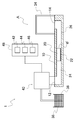
- FIG. 1 is a schematic view showing a microchip liquid feeding system according to a first embodiment of the present invention.
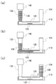
- FIG. 2 is a schematic diagram for explaining the flow of the specimen liquid in the microchip liquid feeding system according to the first embodiment of the present invention.
- FIG. 3 is a schematic diagram for explaining the flow of the specimen liquid in the microchip liquid feeding system according to the first embodiment of the present invention.
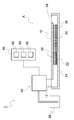
- FIG. 4 is a schematic view showing a microchip liquid feeding system according to a second embodiment of the present invention.
- FIG. 5 is a schematic diagram for explaining the flow of the specimen liquid in the microchip liquid feeding system according to the second embodiment of the present invention.
- FIG. 6 is a schematic diagram for explaining the flow of the specimen liquid in the microchip liquid feeding system according to the second embodiment of the present invention.
- FIG. 1 is a schematic view showing a microchip liquid feeding system according to a first embodiment of the present invention.
- FIG. 2 is a schematic diagram for explaining the flow of the specimen liquid in the microchip liquid feeding system according to the first
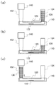
- FIG. 7 is a schematic view showing a microchip liquid feeding system according to an embodiment of the third embodiment of the present invention.
- FIG. 8 is a schematic diagram for explaining the flow of the specimen liquid in the microchip liquid feeding system according to the third embodiment of the present invention.
- FIG. 9 is a schematic diagram for explaining the flow of the specimen liquid in the microchip liquid feeding system according to the third embodiment of the present invention.
- FIG. 10 is a schematic view showing a modification of the microchip liquid feeding system of the present invention.
- FIG. 11 is a schematic view showing a conventional reciprocating microchip liquid feeding system.
- FIG. 12 is a schematic diagram for explaining the flow of the specimen liquid in the conventional reciprocating microchip liquid feeding system.
- FIG. 13 is a schematic diagram for explaining the flow of the sample liquid in the conventional reciprocating microchip liquid feeding system.
- FIG. 14 is a schematic view showing another conventional microchip liquid feeding system.
- FIG. 1 is a schematic view showing a microchip liquid feeding system 1 according to a first embodiment of the present invention.
- the microchip liquid feeding system 1 of the present invention includes a fine flow path 10 having a detection region 20, one side flow path 32 connected to both ends of the fine flow path 10, and the other side. And a flow path assembly A including the flow passage 34.
- a micro pump 40 is connected to the one-side flow passage 32 of the flow path assembly A.
- the sample liquid 36 is filled into the flow path assembly A, and the filled sample liquid 36 is reciprocated inside the flow path assembly A by the micropump 40, thereby feeding the sample liquid. 36 is configured to repeatedly pass through the detection region 20.
- the fine flow path 10 is continuous with the detection area 20, the one-side flow path portion 24 formed continuously on one side of the detection area 20, and the other side of the detection area 20.
- the other side flow path portion 26 formed in this manner is divided into the inside.
- the cross-sectional shape and dimensions of the fine channel 10 are not particularly limited.
- the fine channel 10 is formed in a rectangular cross section having a channel width of 0.5 mm to 3 mm and a channel height of 50 ⁇ m to 500 ⁇ m. Is done.
- the flow path length of the fine flow path 10 is not particularly limited, but is formed, for example, in a range of 2 mm to 30 mm, preferably in a range of 2 mm to 20 mm.
- a reaction field 22 formed by fixing an antibody that specifically reacts with a specific antigen to the bottom surface of the flow path.
- the formation range of the reaction field 22 is appropriately set in consideration of the shape of the microchannel 10 and the amount of supplied analyte so that a desired amount of analyte is efficiently captured by the antibody. Although not particularly limited, for example, it is formed over the entire width of the channel bottom surface of the fine channel 10, and the length in the channel direction is in the range of 1 mm to 3 mm.
- a first inflow / outflow hole 12 is formed at one end of the one-side channel portion 24 of the microchannel 10.
- a second inflow / outflow hole 14 is formed at the other end of the other channel portion 26 of the fine channel 10.
- the cross-sectional shapes and dimensions of the first outflow / inflow holes 12 and the second outflow / inflow holes 14 are not particularly limited.
- the flow path width ⁇ 0.5 mm to ⁇ 3 mm of the fine flow path 10 described above. are formed in a circular shape having substantially the same diameter.
- a one-side flow passage 32 is connected to one end portion of the one-side flow path portion 24.
- the one side flow passage 32 and the fine flow passage 10 are connected to each other through the first outflow / inflow hole 12 described above so as to allow liquid to pass therethrough.
- the one-side flow passage 32 only needs to be configured so that the sample liquid 36 to be reciprocated can flow, and the shape and the like are not particularly limited. Further, it may be formed integrally with the fine flow path 10 or may be connected separately from the fine flow path 10.
- the one-side flow passage 32 of the present embodiment is a pipette 32 formed separately from the fine channel 10 and is configured to be detachable from the fine channel 10.
- the other-side flow passage 34 is connected to the other-side end portion of the other-side flow passage portion 26.
- the other side flow passage 34 and the fine flow passage 10 are connected to each other through the second outflow / inflow hole 14 described above.
- the shape or the like of the other side flow passage 34 is not particularly limited, but is preferably configured as a mixing portion 34 having a larger cross-sectional shape than the second outflow / inflow hole 14 described above. If configured in this way, the sample liquid 36 that has flowed into the other side flow passage (mixing unit 34) is agitated, so that the sample liquid 36 is repeatedly reciprocated without lowering the reaction efficiency in the detection region 20. can do.
- a micropump 40 is connected to the end portion of the one-side flow passage 32 on the side opposite to the fine flow path 10.
- the micropump 40 is, for example, a syringe pump configured to discharge and suck gas (or liquid) into the one-side flow passage 32, and gas (or liquid) is supplied from the micropump 40 to the pipette 32.
- gas (or liquid) is supplied from the micropump 40 to the pipette 32.
- the micropump 40 sucks the gas (or liquid) from the pipette 32 to send the sample liquid 36 from the other side to the one side inside the flow path assembly A.
- a control unit 48 is connected to the micropump 40.
- the control unit 48 includes at least a liquid feeding amount measuring unit 42 that measures the liquid feeding amount of the micropump 40 and a liquid feeding direction control unit 44 that reverses the liquid feeding direction of the micropump 40.
- a storage means 46 is provided for storing a liquid supply amount Qp set in advance as the liquid supply amount. Then, the liquid feed amount measuring means 42 measures the liquid feed amount of the micropump 40, and when the measured liquid feed amount reaches the liquid feed amount Qp stored in the storage means 46, the operating state of the micropump 40. In order to switch from discharge to suction (or from suction to discharge), the liquid feed direction control means 44 issues a command to the micropump 40.
- the embodiment of the micropump 40 is not limited to the above-described one.
- the embodiment of the micropump 40 is not limited to the above-described one. For example, by preparing two micropumps that can only discharge and micropumps that can only suck, and connecting these two micropumps to both ends of the channel assembly A, the inside of the channel assembly A The sample liquid 36 can be sent back and forth.
- FIGS. 2 and 3 are schematic diagrams for explaining the flow of the sample liquid 36 in the microchip liquid feeding system 1 according to the first embodiment of the present invention.
- the arrow in the figure indicates the liquid feeding direction of the sample liquid 36.
- the sample liquid 36 accommodated in the pipette 32 is filled into the fine channel 10, and the gas-liquid interface gl on the other side of the filled sample liquid 36 is connected to the detection region 20. It adjusts so that it may be located in the boundary with the other side channel part 26.
- FIG. 2A This filling operation is performed, for example, by manually controlling the micropump 40.
- the detection region 20 is in an initial state filled with the sample liquid 36.
- the storage unit 46 of the control unit 48 described above stores a liquid supply amount Qp ( ⁇ l) preset as a liquid supply amount of the micropump 40.
- Qp liquid supply amount
- the preset liquid feeding amount Qp in the present embodiment is as shown in the following formula (1).
- the micropump 40 is operated from the initial state shown in FIG. 2A, and air is discharged from the micropump 40 to the pipette 32, as shown in FIGS. 2B and 2C. As described above, the sample liquid 36 is fed from one side of the flow path assembly A to the other side. At this time, the volume Vd ( ⁇ l) of air discharged from the micropump 40 to the pipette 32 is measured by the above-described liquid feeding amount measuring means 42.
- part of the sample liquid 36 that has passed through the detection region 20 flows into the mixing unit 34, and is temporarily stored and stirred.
- FIG 3A shows a state immediately after the operating state of the micropump 40 is switched from discharge to suction.
- the gas-liquid interface gl ′ on one side of the sample liquid 36 is located at the boundary between the detection region 20 and the one-side flow path 24, and the detection region 20 is filled with the sample liquid 36. It has become.
- the liquid feed direction described above is assumed to be that the preset liquid feed amount Qp is fed.
- a command is issued from the control means 44 to the micropump 40, and the micropump 40 operates to discharge air to the pipette 32.
- FIG. 3 shows a state immediately before the operating state of the micropump 40 is switched from suction to discharge.
- the gas-liquid interface gl on the other side of the sample liquid 36 is located at the boundary between the detection region 20 and the other-side flow path portion 26. ing.
- the micro system liquid feeding system 1 of the present invention includes the liquid feeding amount measuring unit 42 that measures the liquid feeding amount of the micro pump 40, and the liquid feeding direction control unit 44 that reverses the liquid feeding direction of the micro pump 40.
- the volume Vd of the gas discharged from the micropump 40 (or the volume Vs of the gas sucked by the micropump 40) reaches a liquid supply amount Qp set in advance as a liquid supply amount of the micropump 40. Then, the liquid feeding direction is automatically reversed. Therefore, the state shown in FIG. 2A is set as an initial state, and a preset liquid supply amount Qp is obtained by subtracting the liquid amount corresponding to the spatial volume of the detection region 20 from the total liquid amount of the sample liquid 36.
- ⁇ Q1 the reciprocated sample liquid 36 repeatedly passes through the detection area 20 while the detection area 20 is constantly filled with the sample liquid 36.
- the sample liquid 36 can be reciprocated without air entering the detection region 20, so that the reaction field The activity of the antibody fixed to 22 does not decrease, and bubbles do not adhere to the antibody, so that the reaction efficiency does not decrease.
- the specimen liquid 36 is reciprocated so that the gas-liquid interface gl (gl ′) of the specimen liquid 36 is located at the boundary of the detection region 20. Therefore, a small amount of the sample liquid 36 can be used for the reaction to the maximum extent.
- a microsystem liquid feeding system 1 of the present invention is applied to a surface plasmon resonance device (SPR device) or a surface plasmon enhanced fluorescence measuring device (SPFS device), the reaction efficiency is high and the variation between individuals is high.
- SPR device surface plasmon resonance device
- SPFS device surface plasmon enhanced fluorescence measuring device
- FIG. 4 is a schematic view showing a microchip liquid feeding system 1 according to a second embodiment of the present invention.
- the volume Vd of air discharged from the micropump 40 (the volume Vs of air sucked by the micropump 40) is equal to the preset amount Qp of the sample liquid 36. As explained. That is, in the first embodiment described above, the air compression rate is not considered.
- a temperature / pressure measuring means 50 for measuring the temperature and pressure inside the flow path assembly A is installed.
- the temperature / pressure measuring means 50 and the control unit 48 are connected, and the temperature measured by the control unit 48 is measured.
- the air compression rate (expansion rate) under the pressure condition is automatically calculated.
- the air volume Vd (Vs) measured by the liquid feeding amount measuring means 42 is corrected by the compression rate (expansion rate), and the corrected air volume V′d (V ′s) is preset.
- the liquid supply direction control means 44 reverses the liquid supply direction.
- microchip liquid feeding system 1 of the present embodiment configured as described above, it is possible to easily perform a more accurate liquid feeding amount control in consideration of the air compression rate (expansion rate).
- the gas-liquid interface gl on the other side of the sample liquid 36 comes to the boundary position between the detection region 20 and the other-side flow path portion 26.
- the microchip liquid feeding system 1 of the present invention is not limited to this.
- the gas-liquid interface gl on the other side of the sample liquid 36 is only a distance L from the detection region 20 in the initial state before starting the reciprocating liquid feeding by the micropump 40.
- the sample liquid 36 may be filled in the flow path assembly A so as to be in a remote position.
- the total liquid volume of the sample liquid 36 is Q ( ⁇ l)
- the liquid volume of the sample liquid 36 corresponding to the spatial volume of the detection region 20 is Q1 ( ⁇ l)
- the microchannel region 28 corresponding to the distance L described above.
- FIG. 7 is a schematic view showing a microchip liquid feeding system 1 according to a third embodiment of the present invention.
- the one-side flow passage 32 is not connected to one end portion of the micro-channel 10, and the micro-channel 10 and the micropump 40 are directly connected. And the point that the sample liquid container 38 for containing the sample liquid 36 is connected to the micropump 40 is different from the above-described embodiment.
- the flow path assembly A includes the fine flow path 10 and the mixing unit 34.
- the sample liquid 36 is reciprocated as shown in FIGS.
- the micropump 40 sucks the sample liquid 36 stored in the sample liquid container 38, and the microfluidic channel 40 is sucked into the microchannel.
- the sample liquid 36 is sent from one side of the flow path assembly A to the other side.
- the liquid amount Qd of the sample liquid 36 discharged from the micropump 40 to the fine flow path 10 is measured by the liquid feeding amount measuring means 42 described above.
- the micropump 40 is moved to the fine flow path 10 as shown in FIG.
- the sample liquid 36 is sent from one side of the flow path assembly A to the other side.
- the volume Vd of air discharged from the micropump 40 to the fine flow path 10 is measured by the above-described liquid feeding amount measuring means 42.
- the gas-liquid interface gl on one side of the sample liquid 36 is located at the boundary between the detection region 20 and the one-side flow path portion 24.
- the detection area 20 is filled with the sample liquid 36.
- the micropump 40 sucks the air in the one-side flow path portion 24 of the fine flow path 10 so that the sample liquid 36 is supplied from the other side of the flow path assembly A as shown in FIG. Liquid is fed to one side.
- the micropump 40 directly removes the sample liquid 36 in the microchannel 10 as shown in FIG. Suction.
- the volume Vs of air sucked by the micropump 40 and the liquid amount Qs of the sample liquid 36 are measured by the liquid feeding amount measuring means 42 described above.
- the gas-liquid interface on one side of the specimen liquid 36 gl is located at the boundary between the detection region 20 and the other-side flow passage portion 26, and returns to the initial state shown in FIG.
- the one-side flow passage 32 is not connected to one end portion of the micro-channel 10, and the micro-channel 10 and the micropump 40 are directly connected. It may be done.
- the microchip liquid feeding system 1 of the present invention may send the sample liquid 36 via a fluid such as air when the sample liquid 36 is reciprocated by the micropump 40.
- the sample liquid 36 may be reciprocated by direct ejection or suction.
- any gas other than the air described above may be used as long as the fluid does not change the properties of the sample liquid 36. It may be a liquid.
- the mixing unit 34 is connected to the other end of the microchannel 10 as the second flow path.
- the mixing portion 34 and the fine channel 10 are connected via the second outflow / inflow hole 14 so as to allow liquid to pass therethrough.
- the microchip liquid feeding system 1 of the present invention is not limited to this.
- the capacity of the microchannel 10 is sufficient for the other channel portion 26 of the microchannel 10 to contain the sample solution 36. If it has, the mixing part 34 does not need to be connected to the other side of the fine flow path 10. In this case, the flow path assembly A is composed of only the fine flow path 10.
Landscapes
- Health & Medical Sciences (AREA)
- Chemical & Material Sciences (AREA)
- Immunology (AREA)
- Life Sciences & Earth Sciences (AREA)
- Hematology (AREA)
- Engineering & Computer Science (AREA)
- Analytical Chemistry (AREA)
- General Health & Medical Sciences (AREA)
- Molecular Biology (AREA)
- Biomedical Technology (AREA)
- Urology & Nephrology (AREA)
- Chemical Kinetics & Catalysis (AREA)
- Clinical Laboratory Science (AREA)
- Dispersion Chemistry (AREA)
- Biotechnology (AREA)
- Microbiology (AREA)
- Cell Biology (AREA)
- Food Science & Technology (AREA)
- Medicinal Chemistry (AREA)
- Physics & Mathematics (AREA)
- Biochemistry (AREA)
- General Physics & Mathematics (AREA)
- Pathology (AREA)
- Automatic Analysis And Handling Materials Therefor (AREA)
- Investigating, Analyzing Materials By Fluorescence Or Luminescence (AREA)
- Investigating Or Analysing Materials By Optical Means (AREA)
Abstract
Description
本発明のマイクロチップ送液システムは、
特定の抗原と反応する抗体が固定された反応場が形成されている検出領域を有する微細流路を少なくとも備えてなる流路アッセンブリと、
前記流路アッセンブリと接続されるとともに、前記特定の抗原を含む検体液を往復送液するマイクロポンプと、を少なくとも備え、
前記マイクロポンプが検体液を往復送液することにより、送液された検体液が前記検出領域を繰り返し通過するように構成されたマイクロチップ送液システムであって、
前記マイクロチップ送液システムは、マイクロポンプからの送液量を計測する送液量計測手段と、マイクロポンプの送液方向を反転させる送液方向制御手段と、を備えており、
前記流路アッセンブリ内に検体液が充填され、前記検出領域を含む流路アッセンブリの一部区間が検体液によって満たされている状態において、前記マイクロポンプによって検体液を往復送液する際に、
前記送液量計測手段によってマイクロポンプからの送液量を計測し、計測された送液量が予め設定された送液量に達した場合には、前記送液方向制御手段によって送液方向を反転させることで、前記検出領域が検体液に満たされた状態のまま、送液された検体液が検出領域を繰り返し通過するように構成されていることを特徴とする。
前記流路アッセンブリが、
一方側の端部に形成された第1の流出入孔と、他方側の端部に形成された第2の流出入孔と、を有する微細流路と、
前記第1の流出入孔を介して、前記微細流路と通液可能に接続された一方側流通路と、
前記第2の流出入孔を介して、前記微細流路と通液可能に接続された他方側流通路と、を少なくとも備えてなるとともに、
前記一方側流通路には、前記マイクロポンプが接続されている。
前記他方側流通路が、
前記微細流路の検出領域を通過した検体液を一時的に貯留するとともに、その貯留した検体液が攪拌されるように構成された混合部であることが望ましい。
表面プラズモン共鳴装置(SPR装置)または表面プラズモン増強蛍光測定装置(SPFS装置)に用いられるものであることが望ましい。
図1は、本発明の第1の実施形態のマイクロチップ送液システム1を示した概略図である。
そして、図2の(a)に示した初期状態からマイクロポンプ40を作動させ、マイクロポンプ40からピペット32に空気を吐出させて、図2の(b)および図2の(c)に示したように、検体液36を流路アッセンブリAの一方側から他方側へと送液する。またこの際、マイクロポンプ40からピペット32に吐出される空気の体積Vd(μl)が、上述した送液量計測手段42によって計測される。
次に、本発明の第2の実施形態のマイクロチップ送液システム1について、図4~図6を基に説明する。
このように、初期状態において、検体液36の一方側の気液界面glが、検出領域20および他方側流路部26との境界位置から距離Lだけ離れた位置となるようにすれば、図5および図6に示したように、検体液36が往復送液される際に、気液界面gl(gl´)と検出領域20とが距離Lだけ離れることとなり、検出領域20に空気が浸入することを確実に防止することができる。
次に、本発明の第3の実施形態のマイクロチップ送液システム1について、図7~図9を基に説明する。
10 微細流路
12 第1の流出入孔
14 第2の流出入孔
20 検出領域
22 反応場
24 一方側流路部
26 他方側流路部
28 領域
32 一方側流通路(ピペット)
34 他方側流通路(混合部)
36 検体液
38 検体液収容器
40 マイクロポンプ
42 送液量計測手段
44 送液方向制御手段
46 記憶手段
48 制御部
50 温度・圧力測定手段
100 マイクロチップ送液システム
110 微細流路
112 第1の流出入孔
114 第2の流出入孔
120 検出領域
122 反応場
132 一方側流通路
134 他方側流通路
136 検体液
140 マイクロポンプ
142 液位確認センサー
144 液位確認センサー
A 流路アッセンブリ
gl,gl´ 気液界面
Claims (4)
- 特定の抗原と反応する抗体が固定された反応場が形成されている検出領域を有する微細流路を少なくとも備えてなる流路アッセンブリと、
前記流路アッセンブリと接続されるとともに、前記特定の抗原を含む検体液を往復送液するマイクロポンプと、を少なくとも備え、
前記マイクロポンプが検体液を往復送液することにより、送液された検体液が前記検出領域を繰り返し通過するように構成されたマイクロチップ送液システムであって、
前記マイクロチップ送液システムは、マイクロポンプからの送液量を計測する送液量計測手段と、マイクロポンプの送液方向を反転させる送液方向制御手段と、を備えており、
前記流路アッセンブリ内に検体液が充填され、前記検出領域を含む流路アッセンブリの一部区間が検体液によって満たされている状態において、前記マイクロポンプによって検体液を往復送液する際に、
前記送液量計測手段によってマイクロポンプからの送液量を計測し、計測された送液量が予め設定された送液量に達した場合には、前記送液方向制御手段によって送液方向を反転させることで、前記検出領域が検体液に満たされた状態のまま、送液された検体液が検出領域を繰り返し通過するように構成されていることを特徴とするマイクロチップ送液システム。 - 前記流路アッセンブリが、
一方側の端部に形成された第1の流出入孔と、他方側の端部に形成された第2の流出入孔と、を有する微細流路と、
前記第1の流出入孔を介して、前記微細流路と通液可能に接続された一方側流通路と、
前記第2の流出入孔を介して、前記微細流路と通液可能に接続された他方側流通路と、を少なくとも備えてなるとともに、
前記一方側流通路には、前記マイクロポンプが接続されていることを特徴とする請求項1に記載のマイクロチップ送液システム。 - 前記他方側流通路が、
前記微細流路の検出領域を通過した検体液を一時的に貯留するとともに、その貯留した検体液が攪拌されるように構成された混合部であることを特徴とする請求項2に記載のマイクロチップ送液システム。 - 前記マイクロチップ送液システムが、
表面プラズモン共鳴装置(SPR装置)または表面プラズモン増強蛍光測定装置(SPFS装置)に用いられるものであることを特徴とする請求項1から3のいずれかに記載のマイクロチップ送液システム。
Priority Applications (3)
| Application Number | Priority Date | Filing Date | Title |
|---|---|---|---|
| EP12782044.7A EP2708901B1 (en) | 2011-05-09 | 2012-05-08 | Microchip liquid feeding system |
| US14/116,219 US9952210B2 (en) | 2011-05-09 | 2012-05-08 | Microchip solution sending system |
| JP2013514011A JP5825344B2 (ja) | 2011-05-09 | 2012-05-08 | マイクロチップ送液システム |
Applications Claiming Priority (2)
| Application Number | Priority Date | Filing Date | Title |
|---|---|---|---|
| JP2011104153 | 2011-05-09 | ||
| JP2011-104153 | 2011-05-09 |
Publications (1)
| Publication Number | Publication Date |
|---|---|
| WO2012153723A1 true WO2012153723A1 (ja) | 2012-11-15 |
Family
ID=47139202
Family Applications (1)
| Application Number | Title | Priority Date | Filing Date |
|---|---|---|---|
| PCT/JP2012/061718 Ceased WO2012153723A1 (ja) | 2011-05-09 | 2012-05-08 | マイクロチップ送液システム |
Country Status (4)
| Country | Link |
|---|---|
| US (1) | US9952210B2 (ja) |
| EP (1) | EP2708901B1 (ja) |
| JP (1) | JP5825344B2 (ja) |
| WO (1) | WO2012153723A1 (ja) |
Cited By (2)
| Publication number | Priority date | Publication date | Assignee | Title |
|---|---|---|---|---|
| WO2015064441A1 (ja) * | 2013-10-31 | 2015-05-07 | コニカミノルタ株式会社 | サンドイッチ-イムノアッセイ法を用いた抗原検出方法 |
| JP2017134017A (ja) * | 2016-01-29 | 2017-08-03 | シスメックス株式会社 | 生体試料撮像装置及び生体試料撮像方法 |
Families Citing this family (3)
| Publication number | Priority date | Publication date | Assignee | Title |
|---|---|---|---|---|
| JP6642592B2 (ja) * | 2016-01-28 | 2020-02-05 | コニカミノルタ株式会社 | 送液方法、ならびにこれを行う検出システムおよび検出装置 |
| CN106092836A (zh) * | 2016-06-07 | 2016-11-09 | 四川大学 | 一种在线检测微波辐照后溶液性质的方法 |
| CN113721015B (zh) * | 2021-09-08 | 2023-03-21 | 中国农业大学 | 微生物自动化检测装置、系统及方法 |
Citations (10)
| Publication number | Priority date | Publication date | Assignee | Title |
|---|---|---|---|---|
| JPH0915115A (ja) * | 1995-06-27 | 1997-01-17 | Sanuki Kogyo Kk | 理化学機器用逆止弁及び該逆止弁を用いた複液混合装置 |
| JP2005134372A (ja) | 2003-10-06 | 2005-05-26 | Matsushita Electric Ind Co Ltd | 被検物質測定装置 |
| JP2006090985A (ja) | 2004-09-27 | 2006-04-06 | Fuji Photo Film Co Ltd | 全反射減衰を利用した測定装置及び方法 |
| WO2006123459A1 (ja) * | 2005-05-20 | 2006-11-23 | Hitachi Chemical Company, Ltd. | 生化学物質の分析方法 |
| JP2008228735A (ja) * | 2003-11-28 | 2008-10-02 | Toshiba Corp | 核酸検出カセット、核酸検出装置及び核酸検出システム |
| JP2009270923A (ja) * | 2008-05-07 | 2009-11-19 | Seiko Epson Corp | 生体物質検出方法 |
| WO2010013334A1 (ja) * | 2008-07-31 | 2010-02-04 | 株式会社フォスメガ | 反応装置及び方法 |
| JP2010243419A (ja) * | 2009-04-09 | 2010-10-28 | Konica Minolta Holdings Inc | 試験デバイス、反応装置及び反応試験方法 |
| WO2011027851A1 (ja) | 2009-09-07 | 2011-03-10 | コニカミノルタホールディングス株式会社 | マイクロチップ送液システム、検体検出装置、及びマイクロチップ送液システムの送液方法 |
| JP2011080935A (ja) * | 2009-10-09 | 2011-04-21 | Konica Minolta Holdings Inc | 測定方法及び表面プラズモン増強蛍光測定装置 |
Family Cites Families (3)
| Publication number | Priority date | Publication date | Assignee | Title |
|---|---|---|---|---|
| US20040028559A1 (en) * | 2001-11-06 | 2004-02-12 | Peter Schuck | Sample delivery system with laminar mixing for microvolume biosensing |
| JP4721414B2 (ja) * | 2005-08-15 | 2011-07-13 | キヤノン株式会社 | 反応カートリッジ、反応装置および反応カートリッジの溶液の移動方法 |
| JP2011080035A (ja) | 2009-06-17 | 2011-04-21 | Mitsui Chemicals Tohcello Inc | ポリ乳酸系成形体の製造方法 |
-
2012
- 2012-05-08 US US14/116,219 patent/US9952210B2/en active Active
- 2012-05-08 WO PCT/JP2012/061718 patent/WO2012153723A1/ja not_active Ceased
- 2012-05-08 EP EP12782044.7A patent/EP2708901B1/en active Active
- 2012-05-08 JP JP2013514011A patent/JP5825344B2/ja active Active
Patent Citations (10)
| Publication number | Priority date | Publication date | Assignee | Title |
|---|---|---|---|---|
| JPH0915115A (ja) * | 1995-06-27 | 1997-01-17 | Sanuki Kogyo Kk | 理化学機器用逆止弁及び該逆止弁を用いた複液混合装置 |
| JP2005134372A (ja) | 2003-10-06 | 2005-05-26 | Matsushita Electric Ind Co Ltd | 被検物質測定装置 |
| JP2008228735A (ja) * | 2003-11-28 | 2008-10-02 | Toshiba Corp | 核酸検出カセット、核酸検出装置及び核酸検出システム |
| JP2006090985A (ja) | 2004-09-27 | 2006-04-06 | Fuji Photo Film Co Ltd | 全反射減衰を利用した測定装置及び方法 |
| WO2006123459A1 (ja) * | 2005-05-20 | 2006-11-23 | Hitachi Chemical Company, Ltd. | 生化学物質の分析方法 |
| JP2009270923A (ja) * | 2008-05-07 | 2009-11-19 | Seiko Epson Corp | 生体物質検出方法 |
| WO2010013334A1 (ja) * | 2008-07-31 | 2010-02-04 | 株式会社フォスメガ | 反応装置及び方法 |
| JP2010243419A (ja) * | 2009-04-09 | 2010-10-28 | Konica Minolta Holdings Inc | 試験デバイス、反応装置及び反応試験方法 |
| WO2011027851A1 (ja) | 2009-09-07 | 2011-03-10 | コニカミノルタホールディングス株式会社 | マイクロチップ送液システム、検体検出装置、及びマイクロチップ送液システムの送液方法 |
| JP2011080935A (ja) * | 2009-10-09 | 2011-04-21 | Konica Minolta Holdings Inc | 測定方法及び表面プラズモン増強蛍光測定装置 |
Non-Patent Citations (1)
| Title |
|---|
| See also references of EP2708901A4 |
Cited By (5)
| Publication number | Priority date | Publication date | Assignee | Title |
|---|---|---|---|---|
| WO2015064441A1 (ja) * | 2013-10-31 | 2015-05-07 | コニカミノルタ株式会社 | サンドイッチ-イムノアッセイ法を用いた抗原検出方法 |
| JPWO2015064441A1 (ja) * | 2013-10-31 | 2017-03-09 | コニカミノルタ株式会社 | サンドイッチ−イムノアッセイ法を用いた抗原検出方法 |
| US10591473B2 (en) | 2013-10-31 | 2020-03-17 | Konica Minolta, Inc. | Antigen detection method using sandwich immunoassay method |
| JP2017134017A (ja) * | 2016-01-29 | 2017-08-03 | シスメックス株式会社 | 生体試料撮像装置及び生体試料撮像方法 |
| WO2017130862A1 (ja) * | 2016-01-29 | 2017-08-03 | シスメックス株式会社 | 生体試料撮像装置及び生体試料撮像方法 |
Also Published As
| Publication number | Publication date |
|---|---|
| JPWO2012153723A1 (ja) | 2014-07-31 |
| EP2708901A1 (en) | 2014-03-19 |
| US20140099236A1 (en) | 2014-04-10 |
| EP2708901A4 (en) | 2014-11-05 |
| JP5825344B2 (ja) | 2015-12-02 |
| EP2708901B1 (en) | 2019-08-07 |
| US9952210B2 (en) | 2018-04-24 |
Similar Documents
| Publication | Publication Date | Title |
|---|---|---|
| CN101971004B (zh) | 用于测量粘度的移液管系统和方法 | |
| US8263025B2 (en) | Flow cell | |
| JP5825344B2 (ja) | マイクロチップ送液システム | |
| CN104412075B (zh) | 用于分配流体的盒 | |
| JP5640980B2 (ja) | マイクロチップ送液システム、検体検出装置、及びマイクロチップ送液システムの送液方法 | |
| US8435464B2 (en) | System and method for pipetting of fluids, method for calibrating the system | |
| JP2006266923A (ja) | マイクロ総合分析システム | |
| JP2015166707A (ja) | マイクロ流路デバイス | |
| US9931630B2 (en) | Autonomous and programmable sequential flow of solutions in capillary microfluidics | |
| JP2002018800A (ja) | ガスクッション式分配マイクロシステム | |
| WO2017061619A1 (ja) | 検体処理チップ、検体処理装置および検体処理方法 | |
| WO2003022438A1 (en) | Dispensing method and apparatus for dispensing very small quantities of fluid | |
| EP0865824A1 (en) | Micromechanical pipetting device | |
| CN104220148A (zh) | 用于流体样品的微流过滤系统和流过滤方法 | |
| JPWO2012172992A1 (ja) | 検体検出装置に用いられるセンサーチップおよびセンサーチップを用いた検体検出装置 | |
| JPH10318150A (ja) | マイクロメカニカルピペット装置 | |
| JP3787578B2 (ja) | マイクロチップの微細流路における液体送液方法 | |
| JP5736975B2 (ja) | マイクロチップ送液システム | |
| EP2226622B1 (en) | Flow cell | |
| JP5476514B2 (ja) | 混合流路で複数の流体を均一に混合する方法 | |
| JP2007292714A (ja) | マイクロ流体システムおよび試料分析装置 | |
| JP4533685B2 (ja) | マイクロ流体装置 | |
| JP2007139500A (ja) | マイクロチップおよびマイクロ総合分析システム | |
| WO2007145040A1 (ja) | 液漏れ防止機構を備えたマイクロ総合分析システム | |
| JP5483616B2 (ja) | フローセルおよびフローセルの送液方法 |
Legal Events
| Date | Code | Title | Description |
|---|---|---|---|
| 121 | Ep: the epo has been informed by wipo that ep was designated in this application |
Ref document number: 12782044 Country of ref document: EP Kind code of ref document: A1 |
|
| ENP | Entry into the national phase |
Ref document number: 2013514011 Country of ref document: JP Kind code of ref document: A |
|
| WWE | Wipo information: entry into national phase |
Ref document number: 2012782044 Country of ref document: EP |
|
| WWE | Wipo information: entry into national phase |
Ref document number: 14116219 Country of ref document: US |
|
| NENP | Non-entry into the national phase |
Ref country code: DE |