WO2012153469A1 - リチウムイオン二次電池用電極、その製造方法及びその電極を用いたリチウムイオン二次電池 - Google Patents
リチウムイオン二次電池用電極、その製造方法及びその電極を用いたリチウムイオン二次電池 Download PDFInfo
- Publication number
- WO2012153469A1 WO2012153469A1 PCT/JP2012/002726 JP2012002726W WO2012153469A1 WO 2012153469 A1 WO2012153469 A1 WO 2012153469A1 JP 2012002726 W JP2012002726 W JP 2012002726W WO 2012153469 A1 WO2012153469 A1 WO 2012153469A1
- Authority
- WO
- WIPO (PCT)
- Prior art keywords
- electrode
- lithium ion
- ion secondary
- active material
- secondary battery
- Prior art date
- Legal status (The legal status is an assumption and is not a legal conclusion. Google has not performed a legal analysis and makes no representation as to the accuracy of the status listed.)
- Ceased
Links
Images

Classifications
-
- H—ELECTRICITY
- H01—ELECTRIC ELEMENTS
- H01M—PROCESSES OR MEANS, e.g. BATTERIES, FOR THE DIRECT CONVERSION OF CHEMICAL ENERGY INTO ELECTRICAL ENERGY
- H01M4/00—Electrodes
- H01M4/02—Electrodes composed of, or comprising, active material
- H01M4/62—Selection of inactive substances as ingredients for active masses, e.g. binders, fillers
- H01M4/628—Inhibitors, e.g. gassing inhibitors, corrosion inhibitors
-
- H—ELECTRICITY
- H01—ELECTRIC ELEMENTS
- H01M—PROCESSES OR MEANS, e.g. BATTERIES, FOR THE DIRECT CONVERSION OF CHEMICAL ENERGY INTO ELECTRICAL ENERGY
- H01M4/00—Electrodes
- H01M4/02—Electrodes composed of, or comprising, active material
- H01M4/04—Processes of manufacture in general
- H01M4/0402—Methods of deposition of the material
- H01M4/0404—Methods of deposition of the material by coating on electrode collectors
-
- H—ELECTRICITY
- H01—ELECTRIC ELEMENTS
- H01M—PROCESSES OR MEANS, e.g. BATTERIES, FOR THE DIRECT CONVERSION OF CHEMICAL ENERGY INTO ELECTRICAL ENERGY
- H01M4/00—Electrodes
- H01M4/02—Electrodes composed of, or comprising, active material
- H01M4/04—Processes of manufacture in general
- H01M4/0471—Processes of manufacture in general involving thermal treatment, e.g. firing, sintering, backing particulate active material, thermal decomposition, pyrolysis
-
- H—ELECTRICITY
- H01—ELECTRIC ELEMENTS
- H01M—PROCESSES OR MEANS, e.g. BATTERIES, FOR THE DIRECT CONVERSION OF CHEMICAL ENERGY INTO ELECTRICAL ENERGY
- H01M4/00—Electrodes
- H01M4/02—Electrodes composed of, or comprising, active material
- H01M4/13—Electrodes for accumulators with non-aqueous electrolyte, e.g. for lithium-accumulators; Processes of manufacture thereof
- H01M4/139—Processes of manufacture
-
- H—ELECTRICITY
- H01—ELECTRIC ELEMENTS
- H01M—PROCESSES OR MEANS, e.g. BATTERIES, FOR THE DIRECT CONVERSION OF CHEMICAL ENERGY INTO ELECTRICAL ENERGY
- H01M4/00—Electrodes
- H01M4/02—Electrodes composed of, or comprising, active material
- H01M4/36—Selection of substances as active materials, active masses, active liquids
- H01M4/362—Composites
- H01M4/366—Composites as layered products
-
- H—ELECTRICITY
- H01—ELECTRIC ELEMENTS
- H01M—PROCESSES OR MEANS, e.g. BATTERIES, FOR THE DIRECT CONVERSION OF CHEMICAL ENERGY INTO ELECTRICAL ENERGY
- H01M4/00—Electrodes
- H01M4/02—Electrodes composed of, or comprising, active material
- H01M4/62—Selection of inactive substances as ingredients for active masses, e.g. binders, fillers
-
- Y—GENERAL TAGGING OF NEW TECHNOLOGICAL DEVELOPMENTS; GENERAL TAGGING OF CROSS-SECTIONAL TECHNOLOGIES SPANNING OVER SEVERAL SECTIONS OF THE IPC; TECHNICAL SUBJECTS COVERED BY FORMER USPC CROSS-REFERENCE ART COLLECTIONS [XRACs] AND DIGESTS
- Y02—TECHNOLOGIES OR APPLICATIONS FOR MITIGATION OR ADAPTATION AGAINST CLIMATE CHANGE
- Y02E—REDUCTION OF GREENHOUSE GAS [GHG] EMISSIONS, RELATED TO ENERGY GENERATION, TRANSMISSION OR DISTRIBUTION
- Y02E60/00—Enabling technologies; Technologies with a potential or indirect contribution to GHG emissions mitigation
- Y02E60/10—Energy storage using batteries
-
- Y—GENERAL TAGGING OF NEW TECHNOLOGICAL DEVELOPMENTS; GENERAL TAGGING OF CROSS-SECTIONAL TECHNOLOGIES SPANNING OVER SEVERAL SECTIONS OF THE IPC; TECHNICAL SUBJECTS COVERED BY FORMER USPC CROSS-REFERENCE ART COLLECTIONS [XRACs] AND DIGESTS
- Y02—TECHNOLOGIES OR APPLICATIONS FOR MITIGATION OR ADAPTATION AGAINST CLIMATE CHANGE
- Y02P—CLIMATE CHANGE MITIGATION TECHNOLOGIES IN THE PRODUCTION OR PROCESSING OF GOODS
- Y02P70/00—Climate change mitigation technologies in the production process for final industrial or consumer products
- Y02P70/50—Manufacturing or production processes characterised by the final manufactured product
Definitions
- the present invention relates to an electrode for a lithium ion secondary battery, a manufacturing method thereof, and a lithium ion secondary battery using the electrode.
- a lithium ion secondary battery is a secondary battery having a high charge / discharge capacity and capable of high output. Currently, it is mainly used as a power source for portable electronic devices, and further expected as a power source for electric vehicles that are expected to become popular in the future.
- a lithium ion secondary battery has an active material capable of inserting and extracting lithium (Li) in a positive electrode and a negative electrode, respectively. The lithium ion secondary battery operates by moving lithium ions in the electrolytic solution provided between both electrodes.
- Lithium ion secondary batteries are required to maintain discharge capacity even after repeated charge and discharge.
- the charge / discharge cycle life of the lithium ion secondary battery is shortened by the gradual reaction between the electrode active material and the electrolytic solution to decompose the electrolytic solution.
- Patent Document 1 it is disclosed that a compound containing polysiloxane, perfluoropolyether, perfluoroalkane and a derivative thereof is mixed in an electrolytic solution to form a film of the above compound on a positive electrode or a negative electrode. Yes. Since these compounds have a smaller surface tension than the electrolytic solution and are insoluble in the electrolytic solution, it is disclosed that when a battery is assembled, a film is formed on the electrode in the battery.
- Patent Document 2 discloses that a lithium ion conductive polymer compound having a polyethylene glycol unit is coated on an active material made of tin oxide or composite tin oxide.
- the present invention has been made in view of the current state of the prior art described above, and its main purpose is to form a coating that can be retained over a long period of time on the surface of the active material layer. It is intended to provide an electrode for a lithium ion secondary battery that can be suppressed and improve the cycle characteristics of the battery, a manufacturing method thereof, and a lithium ion secondary battery using the electrode.
- the inventor has conducted intensive research to achieve the above-described purpose. As a result, it has been found that the cycle characteristics of a lithium ion secondary battery can be improved by forming a film containing modified polydimethylsiloxane on at least a part of the surface of the active material layer.
- the electrode for a lithium ion secondary battery according to the present invention includes a current collector, an active material layer containing a binder formed on the surface of the current collector, and a modified polymer formed on at least a part of the surface of the active material layer. And a film containing dimethylsiloxane, wherein the film is chemically bonded to the binder.
- the above film is preferably formed on the surface of the active material layer by thermally decomposing the polyether chain of the polyether-modified polydimethylsiloxane and chemically bonding with the binder.
- the lithium ion secondary battery of the present invention is characterized in that at least one of the positive electrode and the negative electrode is the electrode for a lithium ion secondary battery.
- the method for producing an electrode for a lithium ion secondary battery according to the present invention includes a slurry preparation step of preparing a slurry by mixing an active material, a binder resin, and a polyether-modified polydimethylsiloxane, and the slurry on the surface of the current collector
- the slurry coating process is applied to the surface of the current collector, and the slurry applied to the surface of the current collector is heated to cure the binder resin and to thermally decompose the polyether chain of the polyether-modified polydimethylsiloxane to chemically react with the binder resin.
- a heat treatment step for bonding is preferably 160 ° C. or higher.
- a coating containing modified polydimethylsiloxane chemically bonded to a binder is formed on at least a part of the surface of the active material layer.
- the lithium ion secondary battery including the lithium ion secondary battery electrode can be a lithium ion secondary battery having excellent cycle characteristics.
- FIG. 1 is a schematic diagram illustrating an electrode for a lithium ion secondary battery according to the present embodiment.
- FIG. 1 shows a current collector 1 and an active material layer 5 formed on the current collector 1.
- the active material 2 and the conductive auxiliary agent 4 are held on the current collector 1 via the binder 3.
- a film 6 chemically bonded to the binder 3 at the location 6a is formed.
- FIG. 1 is a schematic diagram, and the size and shape are not accurate. For example, although the film 6 is shown in a plate shape in FIG. 1, the actual film 6 is indefinite and is formed in a thin film shape along the surface of the active material layer 5.
- the film 6 is chemically bonded to the binder 3 on the surface of the active material layer 5 and is in the form of a film.
- the coating 6 covers at least a part of the surface of the active material layer 5. Therefore, the film 6 also covers the active material 2 on the surface of the active material layer 5.
- the surface of the active material layer 5 may be partially not covered with the coating 6. It is desirable that the entire surface of the active material layer 5 is covered with the coating 6.
- a film 6 is formed on at least a part of the surface of the active material layer 5, and the film 6 is bonded to the binder 3.
- the coating 6 By covering the active material 2 with the coating 6, it is possible to prevent the active material 2 from coming into direct contact with the electrolytic solution. For this reason, it is possible to suppress the electrolytic solution from being decomposed by the active material 2 included in the active material layer 5 during charging / discharging of the battery. Even when the battery is repeatedly charged and discharged, the coating 6 is difficult to be removed from the active material layer 5, so that the decomposition of the electrolytic solution can be suppressed for a long time.
- An electrode for a lithium ion secondary battery of the present invention comprises a current collector, an active material layer, and a modified polydimethylsiloxane chemically bonded to a binder contained in the active material layer on at least a part of the surface of the active material layer. Including a coating.
- the current collector is a chemically inert electronic high conductor that keeps current flowing through the electrode during discharging or charging.
- the current collector can adopt a shape such as a foil or a plate, but is not particularly limited as long as it has a shape according to the purpose.
- a metal foil such as a copper foil, a nickel foil, an aluminum foil, or a stainless steel foil can be suitably used.
- the active material layer includes an active material and a binder. You may include a conductive support agent as needed.
- the active material is a substance that directly contributes to the electrode reaction such as charging reaction and discharging reaction.
- a lithium-containing compound is suitable as the positive electrode active material.
- lithium-containing metal composite oxides such as lithium cobalt composite oxide, lithium nickel composite oxide, and lithium manganese composite oxide can be used.
- metal compounds or polymer materials can be used as the positive electrode active material.
- examples of other metal compounds include oxides such as titanium oxide, vanadium oxide, and manganese dioxide, or disulfides such as titanium sulfide and molybdenum sulfide.
- examples of the polymer material include conductive polymers such as polyaniline and polythiophene.
- a carbon-based material capable of inserting and extracting lithium a metal capable of alloying lithium, an alloy of these metals, a compound of these metals, or a polymer material can be used.
- the carbon-based material examples include non-graphitizable carbon, artificial graphite, coke, graphite, glassy carbon, organic polymer compound fired body, carbon fiber, activated carbon, or carbon black.
- the organic polymer compound fired body refers to a material obtained by firing and carbonizing a polymer material such as phenols and furans at an appropriate temperature.
- metal capable of alloying lithium examples include Al, Si, Zn, Ge, Cd, Sn, and Pb.
- Metal alloys or compounds capable of alloying lithium include ZnLiAl, AlSb, SiB 4 , SiB 6 , Mg 2 Si, Mg 2 Sn, Ni 2 Si, TiSi 2 , MoSi 2 , CoSi 2 , NiSi 2 , and CaSi 2.
- polymer material examples include polyacetylene and polypyrrole.
- the binder is used as a binder for fixing the active material and the conductive additive to the current collector.
- the binder is required to bind the active material and the like in as small an amount as possible.
- the amount is 100% by mass of the total of the active material, the conductive auxiliary, and the binder, and the amount of the binder is 0.5% by mass to It is desirable to be 50% by mass.
- binder examples include a cured product of polyvinylidene fluoride (PVDF), a cured product of a fluorine-based polymer such as polytetrafluoroethylene (PTFE), a cured product of rubber such as styrene butadiene rubber (SBR), polyimide, and polyamideimide.
- PVDF polyvinylidene fluoride
- PTFE polytetrafluoroethylene
- SBR styrene butadiene rubber
- polyimide polyamideimide
- a cured product of an imide polymer or a cured product of an alkoxysilyl group-containing resin can be used.
- the conductive aid is added to increase the conductivity of the electrode layer.
- Carbon black, graphite, acetylene black (AB), ketjen black (KB), vapor grown carbon fiber (Vapor Grown Carbon Fiber: VGCF), etc. are used alone or in combination of two or more as conductive aids.
- the amount of the conductive auxiliary agent to be used is not particularly limited. For example, it can be about 20 to 100 parts by mass with respect to 100 parts by mass of the active material.
- the film containing the modified polydimethylsiloxane is formed on at least a part of the surface of the active material layer.
- the active material layer includes a material that can decompose the electrolytic solution, for example, an active material and a conductive additive. It is said that the electrolytic solution is decomposed by active groups such as OH groups on the surface of the active material under a low voltage and reducing atmosphere.
- active groups such as OH groups on the surface of the active material under a low voltage and reducing atmosphere.
- the film may be formed on at least a part of the surface of the active material layer, but preferably it covers the entire surface of the active material layer.
- the coating By covering the entire surface of the active material layer with the coating, it is possible to suppress the entire active group such as an active material considered to decompose the electrolytic solution from coming into contact with the electrolytic solution, and reliably suppress the decomposition of the electrolytic solution. I can do it.
- the modified polydimethylsiloxane in the present invention refers to a modified product of polydimethylsiloxane having a structure in which a part of the side chain of the polydimethylsiloxane to which the side chain is added is chemically bonded to the binder.
- the main chain is polydimethylsiloxane, which is a main chain
- the side chain added to the polydimethylsiloxane is an organic substance added to the methyl group portion.
- a part of the side chain is chemically bonded to the binder.
- a chemical bond refers to a chemically bonded state, and generally includes ionic bonds, covalent bonds, metal bonds, hydrogen bonds, and the like. Since the chemical bond between the coating and the binder is a chemical bond between a part of the side chain (organic substance) added to polydimethylsiloxane and the binder (organic substance), this chemical bond is mainly a covalent bond.
- the modified polydimethylsiloxane having the above structure is insoluble in an organic solvent and has a high surface activity because the main chain is polydimethylsiloxane, which is a basic skeleton. Due to its properties, the modified polydimethylsiloxane is oriented at the gas-liquid interface during film formation to form a film. Therefore, the modified polydimethylsiloxane forms a thin film on the surface of the active material layer even in a slight amount. Since the coating containing the modified polydimethylsiloxane is insoluble in an organic solvent, it does not dissolve in the electrolytic solution. The coating containing the modified polydimethylsiloxane is chemically bonded to the binder.
- the coating is chemically bonded to the binder, the coating is difficult to peel off from the active material layer even when the active material expands or contracts due to charging / discharging of the electrode. Therefore, the effect of suppressing the decomposition of the electrolytic solution continues for a long time.
- the chemical bond between the coating containing the modified polydimethylsiloxane and the binder specifically means that the reactive group of the binder and the reactive group of the side chain are chemically bonded.
- the side-chain polyether chains are decomposed when heated to about 150 ° C. or higher.
- the reactive group formed by the decomposition of the polyether chain reacts with the reactive group of the binder resin to be chemically bonded.
- the binder resin used at this time is one that is not decomposed at the heating temperature when the reactive group of the side chain and the reactive group of the binder resin are chemically bonded.
- the polyether-modified polydimethylsiloxane those not compatible with the solvent used and the binder resin used can be used.
- the compatibility of the polyether-modified polydimethylsiloxane with respect to the solvent to be used and the binder resin to be used can be adjusted depending on the kind and number of addition of the polyether added to the side chain.
- the compatibility of the polyether-modified polydimethylsiloxane with the solvent used and the binder resin used can also be adjusted by the ratio of the dimethyl group and the polyether-modified group of the polyether-modified polydimethylsiloxane. Such adjustment may be incompatible with the solvent using the polyether-modified polydimethylsiloxane and the binder resin used.
- the manufacturing method of the electrode for lithium ion secondary batteries of this invention has a slurry preparation process, a slurry application
- a slurry creation step an active material, a binder resin, and polyether-modified polydimethylsiloxane are mixed to create a slurry. You may add a solvent and a conductive support agent to a slurry as needed.
- the slurry application step the slurry is applied to the surface of the current collector.
- the binder resin is cured by heating the slurry applied to the surface of the current collector, and the polyether chain of the polyether-modified polydimethylsiloxane is thermally decomposed and chemically bonded to the binder resin.
- the active material, binder resin, polyether-modified polydimethylsiloxane, and conductive additive are the same as those described above.
- the solvent is not particularly limited.
- NMP N-methylpyrrolidone
- methanol methyl isobutyl ketone (MIBK) and the like can be used.
- a general mixing device such as a planetary mixer, a defoaming kneader, a ball mill, a paint shaker, a vibration mill, a reiki machine, or an agitator mill can be used.
- the mixing ratio of the polyether-modified polydimethylsiloxane to the slurry is preferably 0.1% by mass to 0.5% by mass of the polyether-modified polydimethylsiloxane when the entire slurry is 100% by mass.
- the polyether-modified polydimethylsiloxane Since the polyether-modified polydimethylsiloxane has a high surface activity, the surface tension of the entire slurry can be reduced by including the polyether-modified polydimethylsiloxane in the slurry. Therefore, the slurry containing the polyether-modified polydimethylsiloxane is easily applied uniformly to the current collector surface.
- a coating method generally used when producing an electrode for a secondary battery such as a roll coating method, a dip coating method, a doctor blade method, a spray coating method, or a curtain coating method, can be used.
- the coating thickness of the slurry applied to the surface of the current collector is preferably 10 ⁇ m to 20 ⁇ m.
- This slurry contains polyether-modified polydimethylsiloxane.
- the polyether-modified polydimethylsiloxane is insoluble in the solvent and the binder resin and has a high surface activity, and therefore is oriented at the gas-liquid interface. Therefore, the polyether-modified polydimethylsiloxane is oriented on the surface of the slurry applied to the current collector and spreads in a film shape.
- heating is performed at a temperature at which the polyether chain of the polyether-modified polydimethylsiloxane is thermally decomposed and chemically bonded to the binder resin in accordance with the curing temperature of the binder resin to be used. Since the thermal decomposition temperature of the polyether chain of the polyether-modified polydimethylsiloxane is about 150 ° C. or higher, the heating temperature in the heat treatment step is preferably 160 ° C. or higher. When the heating temperature is 160 ° C. or higher, the polyether chain of the polyether-modified polydimethylsiloxane is decomposed and can be easily chemically bonded to the binder resin. The heating temperature is preferably less than the thermal decomposition temperature of the binder resin used.
- an active material layer is formed on the current collector, and a film containing modified polydimethylsiloxane is formed on the surface of the active material layer. Furthermore, the coating containing the modified polydimethylsiloxane is chemically bonded to the binder.
- the lithium ion secondary battery of the present invention at least one of the positive electrode and the negative electrode is the electrode for a lithium ion secondary battery. If at least one of the positive electrode and the negative electrode is an electrode for the lithium ion secondary battery, it is possible to suppress the decomposition of the electrolytic solution by the active material of the positive electrode or the negative electrode, and the lithium ion secondary battery has excellent cycle characteristics. Can have.
- the use of the lithium ion secondary battery of the present invention is not particularly limited, but improvement of cycle characteristics is particularly effective for vehicles that require a long life.
- a lithium ion secondary battery using the above-described electrode for a lithium ion secondary battery can use known battery components other than using the above electrode for a lithium ion secondary battery, and can be manufactured by a known method. I can do it.
- the lithium ion secondary battery of the present invention has a positive electrode, a negative electrode, a separator, and an electrolytic solution.
- the lithium ion secondary battery of the present invention at least one of the positive electrode and the negative electrode is the electrode for a lithium ion secondary battery.
- the separator separates the positive electrode and the negative electrode and allows lithium ions to pass through while preventing a short circuit of current due to contact between the two electrodes.
- a porous film made of synthetic resin such as polytetrafluoroethylene, polypropylene, or polyethylene, or a porous film made of ceramics can be used.
- the electrolytic solution an electrolytic solution that can be used for a lithium ion secondary battery can be used.
- the electrolytic solution includes a solvent and an electrolyte dissolved in the solvent.
- cyclic esters for example, cyclic esters, chain esters and ethers can be used.
- cyclic esters that can be used include ethylene carbonate, propylene carbonate, butylene carbonate, gamma butyrolactone, vinylene carbonate, 2-methyl-gamma butyrolactone, acetyl-gamma butyrolactone, and gamma valerolactone.
- chain esters that can be used include dimethyl carbonate, diethyl carbonate, dibutyl carbonate, dipropyl carbonate, methyl ethyl carbonate, propionic acid alkyl ester, malonic acid dialkyl ester, and acetic acid alkyl ester.
- ethers examples include tetrahydrofuran, 2-methyltetrahydrofuran, 1,4-dioxane, 1,2-dimethoxyethane, 1,2-diethoxyethane, 1,2-dibutoxyethane, and the like.
- a lithium salt such as LiClO 4 , LiAsF 6 , LiPF 6 , LiBF 4 , LiCF 3 SO 3 , LiN (CF 3 SO 2 ) 2 can be used.
- a lithium salt such as LiClO 4 , LiPF 6 , LiBF 4 , LiCF 3 SO 3 in a solvent such as ethylene carbonate, dimethyl carbonate, propylene carbonate, dimethyl carbonate, or the like is from 0.5 mol / l to 1.7 mol / l.
- a solution dissolved at a certain concentration can be used.
- the negative electrode for a lithium ion secondary battery of the present invention was prepared as follows, and a charge / discharge efficiency test and a cycle test were performed using a model battery for evaluation.
- the test used a laminate-type lithium ion secondary battery with the negative electrode as the evaluation electrode.
- Example 1 SiO (manufactured by Aldrich) was prepared as an active material.
- Alkoxy group-containing silane-modified polyamideimide resin as a binder resin (Arakawa Chemical Industries, Ltd., trade name Composeran, product number H901-2, solvent composition: N-methylpyrrolidone (NMP) / xylene (Xyl), curing residue 30%, A viscosity of 8000 mPa ⁇ s, silica in the cured residue, 2 wt%, and the cured residue means a solid content obtained by curing the resin and excluding volatile components).
- MAG artificial graphite (manufactured by Hitachi Chemical Co., Ltd.) was prepared as a buffer material.
- a carbon-based conductive additive specifically, a mixture of two or three types of KB (Ketjen Black) manufactured by Ketjen Black International and graphite was prepared as the conductive auxiliary.
- BYK Chemie Japan Co., Ltd. product name BYK-300 was prepared as a polyether-modified polydimethylsiloxane.
- An appropriate amount of NMP was added as a solvent to this mixture for adjustment, and then polyether-modified polydimethylsiloxane was added to form a slurry. At this time, the amount of the polyether-modified polydimethylsiloxane added was 0.15% by mass based on 100% by mass of the entire slurry.
- the slurry was placed on an electrolytic copper foil having a thickness of 20 ⁇ m, and the slurry was applied to the electrolytic copper foil in a film form using a doctor blade.
- the obtained sheet was dried at 80 ° C. for 20 minutes to volatilize and remove NMP, and then the current collector and the coated material on the current collector were firmly bonded to each other by a roll press. This was punched into a predetermined shape, and the extracted one was heated at 200 ° C. for 2 hours to obtain an electrode having a thickness of about 35 ⁇ m. This electrode was used as the electrode of Example 1.
- the coating thickness is estimated to be about 200 nm from the blending amount of the modified polydimethylsiloxane.
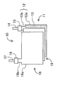
- FIG. 2 is an explanatory diagram showing the configuration of the electrode plate group of the laminated battery. The configuration of the laminate type battery will be described with reference to FIG.
- the laminated battery includes an electrode plate group 10 in which an electrode 11, a counter electrode 16 and a separator 19 are laminated, a laminate film (not shown) that encloses and seals the electrode plate group 10, and a laminate.
- An electrolyte solution (not shown) injected into the film.
- the electrode 11 includes a current collector foil 12 and an active material layer 13 formed on the surface of the current collector foil 12.
- the current collector foil 12 includes a rectangular (26 mm ⁇ 31 mm) coating portion 12a and a tab weld portion 12b extending from a corner of the coating portion 12a.
- An active material layer 13 is formed on one surface of the application portion 12a.
- a nickel-made tab 14 is resistance-welded to the tab weld 12 b of the current collector foil 12. Furthermore, the resin film 15 is adhered to the tab weld portion 12b.
- the counter electrode 16 includes a bowl-shaped (25 mm ⁇ 30 mm) coating portion 16a and a tab weld portion 16b extending from the corner of the coating portion 16a.
- An active material layer (not shown) is formed on one surface of the application portion 16a.
- An aluminum tab 17 is resistance-welded to the tab weld 16b. Further, a resin film 18 is attached to the tab weld 16b.
- a rectangular sheet (27 mm ⁇ 32 mm, thickness 25 ⁇ m) is used for the separator 19.
- the electrode plate group 10 is formed by laminating the coating portion 12 a of the electrode 11, the separator 19, and the coating portion 16 a of the counter electrode 16 so that the negative electrode active material layer and the positive electrode active material layer face each other with the heel separator 19 interposed therebetween. Composed.
- the electrode plate group 10 is covered with a set of two laminated films, the three sides are sealed, and then a predetermined electrolyte is poured into the bag-like laminated film. Thereafter, by sealing the remaining one side, a laminate type battery in which the four sides are hermetically sealed and the electrode plate group 10 and the electrolytic solution are sealed is obtained. Note that some of the tabs 14 and 17 of both poles extend outward for electrical connection with the outside.
- a laminate type battery was produced following the configuration of the laminate type battery described with reference to FIG.
- the electrode of Example 1 was used as the negative electrode.
- the following electrodes were produced as positive electrodes. 20 ⁇ m aluminum foil is used as a current collector, LiNi 1/3 Co 1/3 Mn 1/3 O 2 is used as a positive electrode active material, acetylene black is used as a conductive auxiliary agent, and polyvinylidene fluoride (PVDF) as a binder resin was used.
- An appropriate amount of NMP was added as a solvent to the mixture to prepare a slurry.
- the slurry was placed on an aluminum foil having a thickness of 20 ⁇ m, and the slurry was applied to the aluminum foil in a film form using a doctor blade.
- the obtained sheet was dried at 80 ° C. for 30 minutes to volatilize and remove NMP, and then the current collector and the coating on the current collector were coated with a thickness of 50 ⁇ m by a roll press. That is, it was pressed so that the total thickness of the electrodes was 70 ⁇ m. This was punched into a predetermined shape similar to that of the negative electrode, and the extracted material was heated in vacuum at 120 ° C. for 6 hours to obtain a positive electrode.
- the electrode density of the positive electrode was 2.37 g / cm 3 .
- EC ethylene carbonate
- DEC diethyl carbonate
- a separator made of polypropylene resin was used as the separator.
- Comparative Example 1 The electrode of Comparative Example 1 was prepared in the same manner as in Example 1 except that the polyether-modified polydimethylsiloxane was not added to the slurry, and the laminate type battery using the electrode of Comparative Example 1 was prepared in the same manner as in Example 1. did.
- the load test was performed twice, from the first cycle to 6 cycles and from the 107th cycle to 6 cycles.
- charging is performed by CCCV charging (constant current constant voltage charging) of 0.2C
- discharging is performed by CC discharge (constant current discharging) of 0.2C, 1C, 2C, 3C, 4C, 5C in order from one cycle. went.
- the current that discharges the electric capacity in 1 hour is 1 C
- the current that discharges in 5 hours is 0.2 C. Therefore, the current value of 1C is five times the current value of 0.2C.
- the cycle test was performed from 7 cycles after the first load test to 106 cycles at a constant current of 1 C, and after the second load test was performed, the cycle was continued up to 200 cycles at a constant current of 1 C.
- Each discharge capacity retention rate was calculated based on the discharge capacity of charge / discharge performed at an initial constant current of 1C. This cycle test was carried out at 45 ° C. to be an accelerated test.
- the discharge capacity retention rate (%) was determined by the following formula.
- Discharge capacity maintenance rate (%) (discharge capacity of each cycle / discharge capacity of the seventh cycle performed at a discharge rate of 1 C) ⁇ 100
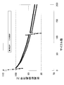
- FIG. 3 shows a graph showing the relationship between the number of cycles and the discharge capacity retention rate (%) for the laminated batteries having the electrodes of Example 1 and Comparative Example 1.
- the battery using the electrode of Example 1 as the evaluation electrode first had a lower reduction rate of the discharge capacity in each cycle than the battery using the electrode of Comparative Example 1 as the evaluation electrode.
- the discharge capacity maintenance rate after 200 cycles is about 83%, whereas in the battery using the electrode of Example 1 as the evaluation electrode, the discharge capacity maintenance after 200 cycles is maintained. The rate was found to be about 85%.
Landscapes
- Chemical & Material Sciences (AREA)
- Chemical Kinetics & Catalysis (AREA)
- Electrochemistry (AREA)
- General Chemical & Material Sciences (AREA)
- Engineering & Computer Science (AREA)
- Manufacturing & Machinery (AREA)
- Composite Materials (AREA)
- Materials Engineering (AREA)
- Battery Electrode And Active Subsutance (AREA)
- Secondary Cells (AREA)
Abstract
Description
ここで図1を用いて本発明のリチウムイオン二次電池用電極を説明する。図1は本実施形態のリチウムイオン二次電池用電極を説明する模式図である。
あるいはLiSnOなどが挙げられる。
本発明のリチウムイオン二次電池用電極の製造方法は、スラリー作成工程と、スラリー塗布工程と、熱処理工程と、を有する。スラリー作成工程では、活物質と、バインダー樹脂と、ポリエーテル変性ポリジメチルシロキサンと、を混合してスラリーを作成する。必要に応じて溶媒、導電助剤をスラリーに添加しても良い。
本発明のリチウムイオン二次電池は、正極及び負極の少なくとも一方が上記リチウムイオン二次電池用電極である。正極及び負極の少なくとも一方が上記リチウムイオン二次電池用電極であれば、正極もしくは負極の活物質などによる電解液の分解を抑制することが出来、リチウムイオン二次電池は、優れたサイクル特性を有することが出来る。本発明のリチウムイオン二次電池は、用途に特に限定はないが、長寿命が求められる車両に対してサイクル特性の向上は特に有効である。
(実施例1)
活物質として、SiO(アルドリッチ社製)を準備した。バインダー樹脂としてアルコキシ基含有シラン変性ポリアミドイミド樹脂(荒川化学工業株式会社製、商品名コンポセラン、品番H901-2、溶剤組成:N-メチルピロリドン(NMP)/キシレン(Xyl)、硬化残分30%、粘度8000mPa・s、硬化残分中のシリカ、2wt%、硬化残分とは樹脂硬化させ揮発性成分を除いた固形分を意味する)を準備した。緩衝材としてMAG人造黒鉛(日立化成工業株式会社製)を準備した。導電助剤としてカーボン系導電助剤、具体的にはケッチェンブラックインターナショナル社製のKB(ケッチェンブラック)と黒鉛等の2~3種類を混ぜたものを準備した。ポリエーテル変性ポリジメチルシロキサンとしてビックケミージャパン株式会社製、品名BYK-300を準備した。
図2は、ラミネート型電池の極板群の構成を示す説明図である。図2を用いてラミネート型電池の構成を説明する。
ポリエーテル変性ポリジメチルシロキサンをスラリーに添加しないこと以外は実施例1と同様にして比較例1の電極を作製し、実施例1と同様にして比較例1の電極を用いたラミネート型電池を作製した。
このラミネート型電池における評価極の評価を次の方法で行った。
上記実施例1の電極を評価極とした電池及び比較例1の電極を評価極とした電池の充放電試験を行った。充放電試験では、負荷試験(6サイクル)とサイクル試験(100サイクル)とを組み合わせた。
Claims (5)
- 集電体と、
該集電体の表面に形成されたバインダーを含む活物質層と、
該活物質層の少なくとも一部の表面に形成された変性ポリジメチルシロキサンを含む被膜と、を有し、
該被膜は該バインダーと化学結合していることを特徴とするリチウムイオン二次電池用電極。 - 前記被膜は、ポリエーテル変性ポリジメチルシロキサンのポリエーテル鎖が熱分解して該バインダーと化学結合することによって、前記活物質層の表面に形成されている請求項1に記載のリチウムイオン二次電池用電極。
- 正極及び負極の少なくとも一方が請求項1~2のいずれか1項に記載のリチウムイオン二次電池用電極であるリチウムイオン二次電池。
- 活物質と、バインダー樹脂と、ポリエーテル変性ポリジメチルシロキサンと、を混合してスラリーを作成するスラリー作成工程と、
該スラリーを集電体の表面に塗布するスラリー塗布工程と、
該集電体の表面に塗布された該スラリーを加熱することにより、該バインダー樹脂を硬化させ、かつ該ポリエーテル変性ポリジメチルシロキサンのポリエーテル鎖を熱分解して該バインダー樹脂と化学結合させる熱処理工程と、
を有するリチウムイオン二次電池用電極の製造方法。 - 前記熱処理工程における加熱温度は160℃以上である請求項4に記載のリチウムイオン二次電池用電極の製造方法。
Priority Applications (2)
| Application Number | Priority Date | Filing Date | Title |
|---|---|---|---|
| US14/116,605 US9214677B2 (en) | 2011-05-12 | 2012-04-19 | Lithium ion secondary battery electrode, manufacturing process for the same, and lithium ion secondary battery using the electrode |
| JP2013513911A JP5664942B2 (ja) | 2011-05-12 | 2012-04-19 | リチウムイオン二次電池用電極、その製造方法及びその電極を用いたリチウムイオン二次電池 |
Applications Claiming Priority (2)
| Application Number | Priority Date | Filing Date | Title |
|---|---|---|---|
| JP2011-107060 | 2011-05-12 | ||
| JP2011107060 | 2011-05-12 |
Publications (1)
| Publication Number | Publication Date |
|---|---|
| WO2012153469A1 true WO2012153469A1 (ja) | 2012-11-15 |
Family
ID=47138962
Family Applications (1)
| Application Number | Title | Priority Date | Filing Date |
|---|---|---|---|
| PCT/JP2012/002726 Ceased WO2012153469A1 (ja) | 2011-05-12 | 2012-04-19 | リチウムイオン二次電池用電極、その製造方法及びその電極を用いたリチウムイオン二次電池 |
Country Status (3)
| Country | Link |
|---|---|
| US (1) | US9214677B2 (ja) |
| JP (1) | JP5664942B2 (ja) |
| WO (1) | WO2012153469A1 (ja) |
Cited By (7)
| Publication number | Priority date | Publication date | Assignee | Title |
|---|---|---|---|---|
| JP2013239378A (ja) * | 2012-05-16 | 2013-11-28 | Dainippon Printing Co Ltd | 非水電解液二次電池用電極板、非水電解液二次電池、電池パック、及び非水電解液二次電池用電極板の製造方法 |
| WO2015182452A1 (ja) * | 2014-05-30 | 2015-12-03 | 住友金属鉱山株式会社 | 被覆リチウム-ニッケル複合酸化物粒子及び被覆リチウム-ニッケル複合酸化物粒子の製造方法 |
| JP2016039087A (ja) * | 2014-08-08 | 2016-03-22 | 日本ゼオン株式会社 | 二次電池用バインダー組成物、二次電池電極用スラリー組成物、二次電池用電極および二次電池 |
| WO2017131147A1 (ja) * | 2016-01-28 | 2017-08-03 | 住友金属鉱山株式会社 | 被覆ニッケル系リチウム-ニッケル複合酸化物粒子の製造方法 |
| JP2019012703A (ja) * | 2018-10-25 | 2019-01-24 | 日本ゼオン株式会社 | 二次電池用バインダー組成物、二次電池電極用スラリー組成物、二次電池用電極および二次電池 |
| JP2022550179A (ja) * | 2019-12-25 | 2022-11-30 | 寧徳新能源科技有限公司 | 負極及びその製造方法 |
| KR102754109B1 (ko) * | 2023-11-08 | 2025-01-14 | 주식회사 비츠로셀 | 고온 수명특성이 향상된 전기이중층 커패시터용 전극 및 그 제조 방법과 이를 포함하는 전기이중층 커패시터 |
Families Citing this family (4)
| Publication number | Priority date | Publication date | Assignee | Title |
|---|---|---|---|---|
| CN105118970B (zh) * | 2015-10-14 | 2018-06-29 | 中航锂电(洛阳)有限公司 | 一种锂离子电池复合极片及其制备方法以及一种锂离子电池 |
| KR102040257B1 (ko) * | 2016-09-13 | 2019-11-04 | 주식회사 엘지화학 | 전극의 제조방법 |
| JP7079140B2 (ja) * | 2018-05-10 | 2022-06-01 | ダイキン工業株式会社 | 電極および電気化学デバイス |
| CN117660883B (zh) * | 2023-12-05 | 2026-04-03 | 南京工业大学 | 一种对水系锌离子电池锌金属负极进行pdms保护层的方法 |
Citations (8)
| Publication number | Priority date | Publication date | Assignee | Title |
|---|---|---|---|---|
| JPH11354104A (ja) * | 1998-04-09 | 1999-12-24 | Denso Corp | 非水電解液二次電池及び電極の製造方法 |
| JP2002008657A (ja) * | 2000-06-23 | 2002-01-11 | Asahi Glass Co Ltd | 二次電源用負極材、二次電源及び負極材の製造法 |
| JP2004265609A (ja) * | 2003-01-23 | 2004-09-24 | Sony Corp | 電極および電池 |
| JP2006049266A (ja) * | 2004-07-09 | 2006-02-16 | Samsung Sdi Co Ltd | リチウム二次電池 |
| JP2007173026A (ja) * | 2005-12-22 | 2007-07-05 | Samsung Sdi Co Ltd | リチウム二次電池及びリチウム二次電池の製造方法 |
| JP2008537293A (ja) * | 2005-04-19 | 2008-09-11 | エルジー・ケム・リミテッド | 架橋高分子の導入によって安全性が向上した電極、及びそれを含む電気化学素子 |
| JP2011070892A (ja) * | 2009-09-25 | 2011-04-07 | Toyota Industries Corp | リチウムイオン二次電池用負極及びその製造方法 |
| JP2011166044A (ja) * | 2010-02-15 | 2011-08-25 | Panasonic Corp | 蓄電デバイス |
Family Cites Families (6)
| Publication number | Priority date | Publication date | Assignee | Title |
|---|---|---|---|---|
| JPH10312803A (ja) | 1997-05-12 | 1998-11-24 | Tokuyama Corp | 非水電解液二次電池用負極活物質および非水電解液二次電池 |
| US20060008706A1 (en) | 2004-07-09 | 2006-01-12 | Takitaro Yamaguchi | Rechargeable lithium battery |
| US7910245B2 (en) | 2005-12-22 | 2011-03-22 | Samsung Sdi Co., Ltd. | Positive active material with a polyether modified silicone oil and rechargeable lithium battery including the same |
| JP5128873B2 (ja) | 2007-08-10 | 2013-01-23 | 株式会社豊田自動織機 | 二次電池用電極及びその製造方法 |
| JP2013502700A (ja) * | 2009-08-24 | 2013-01-24 | シオン・パワー・コーポレーション | 電気化学電池用剥離システム |
| US8652687B2 (en) * | 2009-12-24 | 2014-02-18 | Nanotek Instruments, Inc. | Conductive graphene polymer binder for electrochemical cell electrodes |
-
2012
- 2012-04-19 US US14/116,605 patent/US9214677B2/en not_active Expired - Fee Related
- 2012-04-19 WO PCT/JP2012/002726 patent/WO2012153469A1/ja not_active Ceased
- 2012-04-19 JP JP2013513911A patent/JP5664942B2/ja not_active Expired - Fee Related
Patent Citations (8)
| Publication number | Priority date | Publication date | Assignee | Title |
|---|---|---|---|---|
| JPH11354104A (ja) * | 1998-04-09 | 1999-12-24 | Denso Corp | 非水電解液二次電池及び電極の製造方法 |
| JP2002008657A (ja) * | 2000-06-23 | 2002-01-11 | Asahi Glass Co Ltd | 二次電源用負極材、二次電源及び負極材の製造法 |
| JP2004265609A (ja) * | 2003-01-23 | 2004-09-24 | Sony Corp | 電極および電池 |
| JP2006049266A (ja) * | 2004-07-09 | 2006-02-16 | Samsung Sdi Co Ltd | リチウム二次電池 |
| JP2008537293A (ja) * | 2005-04-19 | 2008-09-11 | エルジー・ケム・リミテッド | 架橋高分子の導入によって安全性が向上した電極、及びそれを含む電気化学素子 |
| JP2007173026A (ja) * | 2005-12-22 | 2007-07-05 | Samsung Sdi Co Ltd | リチウム二次電池及びリチウム二次電池の製造方法 |
| JP2011070892A (ja) * | 2009-09-25 | 2011-04-07 | Toyota Industries Corp | リチウムイオン二次電池用負極及びその製造方法 |
| JP2011166044A (ja) * | 2010-02-15 | 2011-08-25 | Panasonic Corp | 蓄電デバイス |
Cited By (13)
| Publication number | Priority date | Publication date | Assignee | Title |
|---|---|---|---|---|
| JP2013239378A (ja) * | 2012-05-16 | 2013-11-28 | Dainippon Printing Co Ltd | 非水電解液二次電池用電極板、非水電解液二次電池、電池パック、及び非水電解液二次電池用電極板の製造方法 |
| WO2015182452A1 (ja) * | 2014-05-30 | 2015-12-03 | 住友金属鉱山株式会社 | 被覆リチウム-ニッケル複合酸化物粒子及び被覆リチウム-ニッケル複合酸化物粒子の製造方法 |
| JPWO2015182452A1 (ja) * | 2014-05-30 | 2017-04-27 | 住友金属鉱山株式会社 | 被覆リチウム−ニッケル複合酸化物粒子及び被覆リチウム−ニッケル複合酸化物粒子の製造方法 |
| US10374226B2 (en) | 2014-05-30 | 2019-08-06 | Sumitomo Metal Mining Co., Ltd. | Coated lithium-nickel composite oxide particles, and method for producing coated lithium-nickel composite oxide particles |
| JP2016039087A (ja) * | 2014-08-08 | 2016-03-22 | 日本ゼオン株式会社 | 二次電池用バインダー組成物、二次電池電極用スラリー組成物、二次電池用電極および二次電池 |
| US11031585B2 (en) | 2016-01-28 | 2021-06-08 | Sumitomo Metal Mining Co., Ltd. | Method for producing coated nickel-based lithium-nickel composite oxide particles |
| WO2017131147A1 (ja) * | 2016-01-28 | 2017-08-03 | 住友金属鉱山株式会社 | 被覆ニッケル系リチウム-ニッケル複合酸化物粒子の製造方法 |
| JP2017132660A (ja) * | 2016-01-28 | 2017-08-03 | 住友金属鉱山株式会社 | 被覆ニッケル系リチウム−ニッケル複合酸化物粒子の製造方法 |
| JP2019012703A (ja) * | 2018-10-25 | 2019-01-24 | 日本ゼオン株式会社 | 二次電池用バインダー組成物、二次電池電極用スラリー組成物、二次電池用電極および二次電池 |
| JP2022550179A (ja) * | 2019-12-25 | 2022-11-30 | 寧徳新能源科技有限公司 | 負極及びその製造方法 |
| US11978902B2 (en) | 2019-12-25 | 2024-05-07 | Ningde Amperex Technology Limited | Anode and method for preparing the same |
| JP7575451B2 (ja) | 2019-12-25 | 2024-10-29 | 寧徳新能源科技有限公司 | 負極及びその製造方法 |
| KR102754109B1 (ko) * | 2023-11-08 | 2025-01-14 | 주식회사 비츠로셀 | 고온 수명특성이 향상된 전기이중층 커패시터용 전극 및 그 제조 방법과 이를 포함하는 전기이중층 커패시터 |
Also Published As
| Publication number | Publication date |
|---|---|
| JPWO2012153469A1 (ja) | 2014-07-31 |
| JP5664942B2 (ja) | 2015-02-04 |
| US20140087252A1 (en) | 2014-03-27 |
| US9214677B2 (en) | 2015-12-15 |
Similar Documents
| Publication | Publication Date | Title |
|---|---|---|
| JP5664942B2 (ja) | リチウムイオン二次電池用電極、その製造方法及びその電極を用いたリチウムイオン二次電池 | |
| JP5664943B2 (ja) | リチウムイオン二次電池用電極及びその製造方法、並びにその電極を用いたリチウムイオン二次電池 | |
| JP5035313B2 (ja) | リチウムイオン二次電池用負極及びその製造方法 | |
| JP5263416B1 (ja) | 二次電池およびそれを搭載した車両 | |
| JP2014165007A (ja) | 非水系二次電池用負極とその製造方法及び非水系二次電池 | |
| JP5668845B2 (ja) | リチウムイオン二次電池用電極及びその製造方法、並びにその電極を用いたリチウムイオン二次電池 | |
| JP2015011922A (ja) | リチウムイオン二次電池用負極及びリチウムイオン二次電池 | |
| JP5482858B2 (ja) | リチウムイオン二次電池 | |
| JP2013175315A (ja) | リチウムイオン二次電池および車両 | |
| JP6061143B2 (ja) | リチウムイオン二次電池用正極及びリチウムイオン二次電池 | |
| JP6048312B2 (ja) | リチウムイオン二次電池用負極及びリチウムイオン二次電池 | |
| JP5534377B2 (ja) | リチウムイオン二次電池用正極活物質およびそれを有するリチウムイオン二次電池 | |
| JP2014082084A (ja) | リチウムイオン二次電池 | |
| JP5557067B1 (ja) | リチウムイオン二次電池用正極及びリチウムイオン二次電池 | |
| JP2014149989A (ja) | リチウムイオン二次電池用活物質、それを有するリチウムイオン二次電池用電極及びリチウムイオン二次電池 | |
| JP5862490B2 (ja) | リチウムイオン二次電池 | |
| JP6011634B2 (ja) | 非水電解質二次電池 | |
| EP3121883A1 (en) | Electrode for non-aqueous electrolyte secondary battery | |
| JP2014186837A (ja) | リチウムイオン二次電池用正極及びリチウムイオン二次電池 | |
| JP2014238943A (ja) | リチウムイオン二次電池用集電体、リチウムイオン二次電池用電極及びリチウムイオン二次電池 | |
| JP2013175314A (ja) | リチウムイオン二次電池および車両 | |
| JP5999430B2 (ja) | リチウムイオン二次電池用正極活物質およびそれを有するリチウムイオン二次電池 | |
| JP5857943B2 (ja) | 非水電解質二次電池 | |
| JP2013175313A (ja) | リチウムイオン二次電池および車両 |
Legal Events
| Date | Code | Title | Description |
|---|---|---|---|
| 121 | Ep: the epo has been informed by wipo that ep was designated in this application |
Ref document number: 12782063 Country of ref document: EP Kind code of ref document: A1 |
|
| ENP | Entry into the national phase |
Ref document number: 2013513911 Country of ref document: JP Kind code of ref document: A |
|
| WWE | Wipo information: entry into national phase |
Ref document number: 14116605 Country of ref document: US |
|
| NENP | Non-entry into the national phase |
Ref country code: DE |
|
| 122 | Ep: pct application non-entry in european phase |
Ref document number: 12782063 Country of ref document: EP Kind code of ref document: A1 |