WO2012153439A1 - 角加速度検出素子 - Google Patents
角加速度検出素子 Download PDFInfo
- Publication number
- WO2012153439A1 WO2012153439A1 PCT/JP2011/079139 JP2011079139W WO2012153439A1 WO 2012153439 A1 WO2012153439 A1 WO 2012153439A1 JP 2011079139 W JP2011079139 W JP 2011079139W WO 2012153439 A1 WO2012153439 A1 WO 2012153439A1
- Authority
- WO
- WIPO (PCT)
- Prior art keywords
- angular acceleration
- support beam
- axis
- detection
- weight
- Prior art date
Links
Images


Classifications
-
- G—PHYSICS
- G01—MEASURING; TESTING
- G01C—MEASURING DISTANCES, LEVELS OR BEARINGS; SURVEYING; NAVIGATION; GYROSCOPIC INSTRUMENTS; PHOTOGRAMMETRY OR VIDEOGRAMMETRY
- G01C19/00—Gyroscopes; Turn-sensitive devices using vibrating masses; Turn-sensitive devices without moving masses; Measuring angular rate using gyroscopic effects
- G01C19/56—Turn-sensitive devices using vibrating masses, e.g. vibratory angular rate sensors based on Coriolis forces
-
- G—PHYSICS
- G01—MEASURING; TESTING
- G01P—MEASURING LINEAR OR ANGULAR SPEED, ACCELERATION, DECELERATION, OR SHOCK; INDICATING PRESENCE, ABSENCE, OR DIRECTION, OF MOVEMENT
- G01P15/00—Measuring acceleration; Measuring deceleration; Measuring shock, i.e. sudden change of acceleration
- G01P15/02—Measuring acceleration; Measuring deceleration; Measuring shock, i.e. sudden change of acceleration by making use of inertia forces using solid seismic masses
- G01P15/08—Measuring acceleration; Measuring deceleration; Measuring shock, i.e. sudden change of acceleration by making use of inertia forces using solid seismic masses with conversion into electric or magnetic values
- G01P15/0888—Measuring acceleration; Measuring deceleration; Measuring shock, i.e. sudden change of acceleration by making use of inertia forces using solid seismic masses with conversion into electric or magnetic values for indicating angular acceleration
Definitions
- the present invention relates to an angular acceleration detection element that detects angular acceleration acting around a detection axis.
- a certain type of angular acceleration detection element includes a rotating weight, a support beam, and a detection unit (see, for example, Patent Documents 1 and 2).
- the support beam extends in a direction perpendicular to the detection axis, and both ends thereof are connected to the rotary weight and the fixed portion.
- the rotary weight rotates (swings) with respect to the fixed portion by the action of the rotational inertia force associated therewith.
- the support beam is deformed as the rotating weight rotates, and the detection unit detects the stress generated in the support beam.
- the angular acceleration around the detection axis can be measured from the detection signal of the detection unit.
- the rotary weight is also rotated by the translational inertia force. Then, the translational inertia force becomes a noise factor of the detection signal, and the detection accuracy of the angular acceleration around the detection axis is lowered.
- the angular acceleration detecting element is formed in a symmetrical shape with the center of gravity of the rotating weight as the center.
- an annular rotary weight is supported from the inside by a plurality of support beams arranged symmetrically about the center of gravity.
- the rotating weight is supported from the outside by a plurality of support beams arranged symmetrically about the center of gravity.
- the angular acceleration detection element since the plurality of support beams receive the inertial force received by the rotating weight in a distributed manner, when the angular acceleration detection element is configured at a predetermined natural frequency, the stress generated on the beam per angular acceleration is small. Therefore, there is a problem that the sensitivity of detecting angular acceleration is lowered.
- An object of the present invention is to provide an angular acceleration detecting element capable of realizing a high detection sensitivity by reducing the number of substantial support beams while ensuring the rotational balance of the rotary weight.
- the present invention relates to an angular acceleration detection element including a rotary weight, a fixed portion, a support beam, and a detection portion.
- the rotary weight rotates around the detection axis by the action of the rotational inertia force around the predetermined detection axis.
- the fixing portion is provided at a position away from the rotating weight.
- the support beam is provided between the fixed part and the rotary weight on a plane orthogonal to the detection axis, and elastically supports the rotary weight with respect to the fixed part.
- the detection unit outputs a detection signal based on the stress generated in the support beam.
- the rotating weight is such that the position of the center of gravity in the orthogonal plane overlaps the support beam. In this configuration, it is possible to balance the rotation of the rotary weight only with a single support beam that overlaps the position of the center of gravity of the rotary weight.
- the angular acceleration detection element includes a plurality of support beams in which neutral surfaces of stress acting as the rotation weight rotates around a detection axis, and the rotation weight has a center of gravity in the orthogonal plane. The position overlaps the neutral plane.
- the neutral surfaces of the stresses acting on each of the multiple support beams are the same, so the total stress distribution of the multiple support beams is substantially equivalent to the stress distribution of a single support beam. Become. For this reason, the rotational balance of the rotary weight can be achieved substantially by only a single support beam.
- the rotating weight of the above-described angular acceleration detection element is configured in a thin plate shape having a direction along the detection axis as a thickness direction.
- the rotary inertia force per angular acceleration can be increased.
- the width of the support beam required to maintain the natural frequency increases and the length of the support beam decreases. This contributes to increasing the detection sensitivity of angular acceleration.
- the rotating weight of the above-described angular acceleration detection element is configured to have a shape having a major axis direction and a minor axis direction along the orthogonal plane.
- the moment of inertia of the rotating weight around the detection axis is further increased, so that the rotational inertia force per angular acceleration can be further increased.
- the element occupation area required in order to obtain the same angular acceleration detection sensitivity can be reduced, and cost reduction and size reduction can be advanced.
- the support beam of the above-described angular acceleration detection element is configured with the major axis direction of the rotating weight as the length direction.
- the rotary weight having this configuration has a large moment of inertia around the short axis, and the rotary inertia force around the short axis due to disturbance vibrations becomes large. Therefore, if the minor axis direction of the rotating weight is the length direction of the support beam, the support beam is twisted due to the rotational inertial force around the minor axis, and excessive stress concentration occurs at the edge portion of the support beam, resulting in reduced impact resistance performance. Resulting in.
- the length direction of the support beam to the long axis direction of the rotating weight as described above, it is possible to prevent the support beam from being twisted by the rotational inertia force around the short axis and to concentrate stress on the edge portion of the support beam. Can be avoided.
- the rotating weight since the rotational balance of the rotating weight is balanced only by a substantially single support beam that supports the rotating weight, the rotating weight does not rotate even if a translational inertial force is applied. Since the number of typical support beams is reduced, the stress generated in the support beams is increased. From these things, the detection accuracy of angular acceleration can be improved.
- the thickness direction of the angular acceleration detection element is the Z-axis of the orthogonal coordinate system
- the length direction of the support beam is the Y-axis direction
- the width direction of the support beam is the X-axis direction.
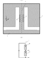
- FIG. 1A is a perspective view showing the configuration of the angular acceleration detection element 1 according to the first embodiment of the present invention
- FIG. 1B is a plan view of the angular acceleration detection element 1.
- the angular acceleration detection element 1 is composed of an integral rectangular plate in which a groove penetrating between the upper and lower surfaces perpendicular to the Z-axis is formed. Prepare. The rectangular plate is cut out by surface processing of a semiconductor wafer. Semiconductor wafer surface processing has matured processing technology and processing apparatus performance, and can efficiently manufacture a plurality of rectangular plates with high accuracy.
- the fixing portion 4 is provided in a rectangular shape at a position deviated from the center of the XY plane of the rectangular plate, and is fixed to at least one of the upper surface and the lower surface of a housing (not shown).
- the rotary weight 2 is configured by providing a rectangular opening in a rectangular plate so as to surround the fixed portion 4 on the XY plane.
- the support beam 3 is provided between the fixed portion 4 and the rotary weight 2 on the XY plane so as to extend in a rectangular shape in the positive direction of the Y axis, and the upper and lower surfaces of the rotary weight 2 float from a housing (not shown). In this state, the rotating weight 2 is supported by the fixed portion 4.
- the detection unit 5 (not shown) outputs a detection signal corresponding to the stress acting on the support beam 3.
- the center position of each of the support beam 3 and the fixed portion 4 in the X-axis coordinate is made to coincide with the center position of the rotary weight 2.
- the center position of the fixed portion 4 in the Y-axis coordinates is shifted from the center position of the rotary weight 2 in the Y-axis negative direction.
- the center position of the support beam 3 in the Y-axis coordinates is shifted from the center position of the rotary weight 2 in the positive Y-axis direction and coincides with the center of gravity of the rotary weight 2 in the Y-axis coordinates.
- the rotating weight 2 rotates (oscillates) around the Z axis with respect to the fixed portion 4 in the XY plane by the rotation inertial force around the Z axis.
- Angular acceleration is detected using the Z axis as a detection axis.
- FIG. 2 is a diagram for explaining a distribution of stress generated in the support beam 3 when a rotational inertial force around the Z axis is applied.
- the angular acceleration detection element 1 is shown rotating in a clockwise direction when viewed from the positive direction of the Z axis.
- the rotary weight 2 rotates counterclockwise as viewed from the positive direction of the Z axis with respect to the fixed portion 4, and a counterclockwise rotational inertia force acts on the support beam 3 as viewed from the positive direction of the Z axis. .
- the support beam 3 is subjected to compressive stress in a region near the side surface in the negative direction of the X axis and is subjected to tensile stress in a region near the side surface in the positive direction of the X axis, and bends in the negative direction of the X axis.
- the center plane in the width direction of the support beam 3 is a neutral plane where the stress acts as a boundary between the tensile stress and the compressive stress, and it rotates on this center plane as viewed in the XY plane.
- the gravity center position (illustrated by x) of the weight 2 overlaps.
- FIG. 3 is a diagram illustrating the configuration of the detection unit 5.
- FIG. 3A is a plan view of the vicinity of the support beam 3
- FIG. 3B is a circuit diagram of the detection unit 5.
- the detection unit 5 includes piezoresistors 5 ⁇ / b> A and 5 ⁇ / b> B whose longitudinal direction is the Y-axis direction on the upper surface of the support beam 3.
- Piezoresistors 5A and 5B can be formed on a semiconductor wafer by using a semiconductor process, so that a fine position and shape can be made highly accurate.
- These piezoresistors 5A and 5B are arranged in parallel on both sides of the neutral surface of the support beam 3, and are connected in series with each other and connected to a constant voltage source.
- the piezoresistors 5A and 5B are reversely expanded and contracted.
- the piezoresistors 5A and 5B increase in resistance value when extended, and decrease in resistance value when shortened. Therefore, since the voltage dividing ratio by the piezoresistors 5A and 5B varies, it is possible to detect the stress acting on the support beam 3 from the voltage across the piezoresistors 5A and 5B.
- FIG. 4 is a diagram for explaining the deformation of the support beam and the change in piezoresistance due to the action of various accelerations.
- FIG. 4 (A) shows a state in which a rotational inertia force counterclockwise as viewed from the positive direction of the Z-axis is applied to the angular acceleration detection element 1.
- the support beam 3 is curved in the XY plane, the piezoresistor 5A is extended, and the piezoresistor 5B is shortened.
- the extended piezoresistor 5A has an increased resistance value, and the shortened piezoresistor 5B has a decreased resistance value.
- the detection part 5 the both-ends voltage of the piezoresistor 5A increases, and the both-ends voltage of the piezoresistor 5B decreases.
- FIG. 4B shows a state in which a rotational inertia force counterclockwise as viewed from the positive direction of the X-axis acts on the angular acceleration detection element 1.
- the support beam 3 is curved in the YZ plane, and both the piezoresistors 5A and 5B are shortened to lower the resistance value.
- the detection part 5 the change of the resistance value of the piezoresistor 5A and the change of the resistance value of the piezoresistor 5B are canceled, and the divided voltage is maintained.
- FIG. 4C shows a state in which a rotational inertia force counterclockwise as viewed from the positive direction of the Y-axis acts on the angular acceleration detection element 1.
- the support beam 3 is twisted in the XZ plane.
- the same twist occurs in the piezoresistors 5A and 5B, and the changes in the resistance values coincide. Therefore, in the detection unit 5, the change in the resistance value in the piezoresistor 5A and the change in the resistance value in the piezoresistor 5B are both canceled out, and the divided voltage is maintained.
- FIG. 4 (D) shows a state in which the translational inertia force in the positive direction of the X-axis acts on the angular acceleration detection element 1.
- the support beam 3 is curved in the XY plane.
- the same bending occurs in the piezoresistors 5A and 5B, and the changes in resistance values coincide. Therefore, in the detection unit 5, the change in the resistance value in the piezoresistor 5A and the change in the resistance value in the piezoresistor 5B are both canceled out, and the divided voltage is maintained.
- FIG. 4 (E) shows a state in which a translational inertia force in the positive direction of the Y-axis is applied to the angular acceleration detection element 1.
- the support beam 3 extends in the Y-axis direction.
- the piezoresistors 5A and 5B expand in the same manner and the changes in resistance value coincide.
- the detection part 5 the change of the resistance value of the piezoresistor 5A and the change of the piezoresistor 5B resistance value are canceled, and the divided voltage is maintained.
- FIG. 4F shows a state in which the translational inertia force in the positive direction of the Z-axis is applied to the angular acceleration detection element 1.
- the support beam 3 is curved in the YZ plane.
- the piezoresistors 5A and 5B are similarly expanded and contracted so that the changes in the resistance values coincide. Therefore, in the detection unit 5, the change in the resistance value in the piezoresistor 5A and the change in the resistance value in the piezoresistor 5B are both canceled out, and the divided voltage is maintained.
- the output voltage changes only in the state where the rotational inertia force around the Z axis is applied.
- the rotation angle ⁇ around the Z axis of the rotary weight 2 with respect to the fixed portion 4 is proportional to the angular acceleration ⁇ around the Z axis as shown by the following equation, and is a structure comprising the rotary weight 2, the support beam 3, and the fixed portion 4. Is inversely proportional to the square of the natural frequency f 0 around the Z axis.
- the natural frequency f 0 be an appropriate set value. Therefore, when the natural frequency f 0 is determined, the rotation angle ⁇ / ⁇ per unit angular acceleration is uniquely determined as in the following equation.
- the natural frequency f 0 depends on a plurality of shape parameters of the structure composed of the rotary weight 2, the support beam 3, and the fixed portion 4, and the dimensions of each part can be adjusted even when the number of support beams is different. Can be matched. Therefore, if the natural frequency f 0 is the same, the rotation angle ⁇ when the same angular acceleration is applied is the same.
- FIG. 5A is a plan view showing a configuration of an angular acceleration detection element 10A according to a comparative configuration.
- the angular acceleration detection element 10A includes two support beams, and is configured in a symmetric shape with the center of gravity of the rotating weight as the center.
- FIG. 5B is a plan view showing the configuration of the angular acceleration detection element 10B according to the comparative configuration.
- the angular acceleration detection element 10B includes four support beams, and is configured in a symmetric shape with respect to the position of the center of gravity of the rotary weight.
- the external dimensions 2 mm ⁇ 2 mm ⁇ 200 ⁇ m are set together with the angular acceleration detection element 1 according to the embodiment, the rotary weight 2 and the fixed portion 4 have the same shape, and the natural frequency f 0 is adjusted by adjusting the dimensions of the support beam. Were matched at 2.0 kHz.
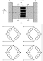
- FIG. 5C is a diagram showing the dimensions and performance of each part in each analysis example.
- the number n of support beams is 1, the length (Y-axis direction dimension) Ly of the support beam is 110 ⁇ m, and the width (X-axis direction dimension) Lx of the support beam is 20 ⁇ m.
- the natural frequency f 0 is set to 2.0 kHz.
- the number n of support beams is 2, the length (Y-axis direction dimension) Ly of the support beam is 441 ⁇ m, and the width (X-axis direction dimension) Lx of the support beam is 10 ⁇ m.
- the natural frequency f 0 is set to 2.0 kHz.
- the number n of support beams is 4, the length (Y-axis direction dimension) Ly of the support beam is 640 ⁇ m, and the width (X-axis direction dimension) Lx of the support beam is 10 ⁇ m.
- the natural frequency f 0 is set to 2.0 kHz.
- the deflection angle ⁇ ′ of the support beam is expressed by the product of the length Ly of the support beam and the deflection curvature 1 / ⁇ of the support beam as shown in the following equation.
- the stress ⁇ generated in the vicinity of the piezoresistors 5A and 5B in the support beam 3 is the distance x from the neutral surface of the support beam to the piezoresistors 5A and 5B and the deflection curvature 1 / ⁇ of the support beam as shown in the following equation.
- the product of the longitudinal elastic modulus E of the material of the support beam is the product of the longitudinal elastic modulus E of the material of the support beam.
- the stress ⁇ generated in the support beam 3 per deflection angle ⁇ ′ of the support beam is increased by shortening the support beam length Ly and increasing the distance x from the neutral plane to the piezoresistors 5A and 5B. can do.
- the stress ⁇ / ⁇ per unit angular acceleration generated in the vicinity of the piezoresistors 5A and 5B in the support beam 3 is also shorter than the support beam length Ly, and the distance x from the neutral plane to the piezoresistors 5A and 5B is x. It can be increased by increasing. This can be confirmed also by the finite element analysis shown in FIG.
- the support beam length Ly is the shortest, and the maximum value per unit angular acceleration of the stress acting on the support beam 3 is 73 Pa / (rad / s 2 ).
- the angular acceleration detecting element 10A according to the comparative example has a longer support beam length Ly, and the maximum value of the stress acting on the support beam 3 per unit angular acceleration is 49 Pa / (rad / s 2 ).
- the angular acceleration detecting element 10B according to the comparative example has a longer support beam length Ly, and the maximum value per unit angular acceleration of the stress acting on the support beam 3 is 29 Pa / (rad / s 2 ).
- the number of support beams is one and the stress acting on the support beam 3 is large, so that the rotational inertia force received by the support beam from the rotating weight is more concentrated.
- the stress generated in the support beam increases, and the amount of deformation of the piezoresistors 5A and 5B increases, resulting in high detection sensitivity.
- an example in which the outer shape of the rotary weight 2 viewed from the Z-axis direction is a rectangle is shown, but other shapes such as a circle and a star may be used.
- the example which makes the internal shape of the rotary weight 2 substantially rectangular was shown, this may also be another shape.
- fixed part 4 a rectangle was shown, this may be another shape.
- the example which makes the shape of a support beam a rectangle was shown, this may also be another shape.
- each part is configured by surface processing of a semiconductor wafer
- the detection unit 5 is configured by piezoresistors 5A and 5B.
- stress can be finally converted into an electrical signal. Any other configuration may be used as long as it is a means regardless of the detection principle, the manufacturing method, or the constituent material.
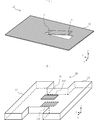
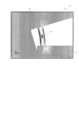
- FIG. 6A is a perspective view of the angular acceleration detecting element 11 according to the second exemplary embodiment of the present invention in a deformed state.
- FIG. 6B is a schematic diagram showing the peripheral structure of the support beam 13 of the angular acceleration detection element 11.
- the angular acceleration detection element 11 includes a rotary weight 12, a support beam 13, a fixed portion 14, and a detection portion 15 (not shown).
- the rotary weight 12, the support beam 13, and the fixed portion 14 can employ substantially the same configuration as in the first embodiment.
- the main difference from the first embodiment is that piezoresistors 15A and 15B provided in the detection unit 15 (not shown) are arranged on the upper and lower surfaces of the support beam 13, and angular acceleration is detected using the X axis as a detection axis. It is.
- FIG. 7 is a diagram for explaining a stress distribution generated in the support beam 13 when a rotational inertial force around the X axis is applied.
- the figure shows a state in which the angular acceleration detection element 11 rotates counterclockwise when viewed from the positive direction of the X axis.
- the rotary weight 12 rotates clockwise as viewed from the X-axis positive direction with the fixed portion 14 as a reference, and a clockwise rotational inertial force as viewed from the X-axis positive direction acts on the support beam 13.
- the support beam 13 is subjected to a compressive stress in a region near the upper surface in the positive direction of the Z axis, and a tensile stress is applied to a region in the vicinity of the lower surface in the negative direction of the Z axis. It will be.
- the center surface in the thickness direction of the support beam 13 becomes a boundary between the tensile stress and the compressive stress and becomes a neutral surface (illustrated by a one-dot chain line) where no stress acts.
- the center of gravity (illustrated by x) of the rotary weight 12 in the YZ plane is positioned on this neutral plane, so that the rotation balance of the rotary weight 12 around the X axis is secured and the detection unit 15 ( The angular acceleration around the X axis can be detected with high detection sensitivity. In this manner, the angular acceleration detection element can be configured.
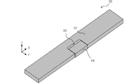
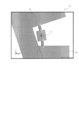
- FIG. 8 is a perspective view showing the configuration of the angular acceleration detection element 91 according to the third embodiment.
- the angular acceleration detection element 91 is made of a rectangular plate having a groove penetrating between the upper and lower surfaces perpendicular to the Z axis, and includes a rotary weight 92, a support beam 93, a fixing portion 94, and a detection portion 95 (not shown).
- the rotary weight 92 is U-shaped with the Y-axis negative direction open, and the X-axis direction is the long axis and the Y-axis direction is the short axis.
- the center of the support beam 93 coincides with the center of gravity of the rotary weight 92, and the Y-axis direction is the length direction and the X-axis direction is the width direction.
- the fixing portion 94 is provided in the opening of the rotating weight 92 and is fixed to a housing (not shown) at least one of the upper surface and the lower surface, and supports the rotating weight 92 via the support beam 93.
- the rotary weight 92 rotates (swings) around the Z axis with respect to the fixed portion 94 in the XY plane by the action of the rotational inertia force around the Z axis.
- Angular acceleration can be detected using the Z axis as a detection axis.
- the rotary weight 92 has a shape having the major axis in the X-axis direction, the moment of inertia around the Z-axis is large, and the square area of the same element-occupied area is larger than when the rotary weight has a square shape.
- the rotational inertia force per acceleration can be increased. Therefore, the support beam 93 can be made thick and short while maintaining the natural frequency of the angular acceleration detection element 91, and the angular acceleration detection sensitivity can be increased.
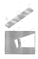
- FIG. 9A is a perspective view of the angular acceleration detection element 21 according to the fourth embodiment.
- the angular acceleration detection element 21 is formed of a rectangular plate in which a groove penetrating between the upper and lower surfaces perpendicular to the Z axis is formed, and includes a rotary weight 22, a support beam 23, a fixing unit 24, and a detection unit 25 (not shown).
- the rotary weight 22 has a U-shape in which the positive direction of the X axis is open, and the Y axis direction is the long axis and the X axis direction is the short axis.
- the center of the support beam 23 coincides with the center of gravity of the rotary weight 22, and the Y-axis direction is the length direction and the X-axis direction is the width direction.
- the fixing unit 24 is provided in the opening of the rotary weight 22 and is fixed to at least one of the upper surface and the lower surface of a housing (not shown), and supports the rotary weight 22 via the support beam 23.
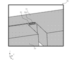
- FIG. 9B is a diagram for explaining a stress distribution generated in the support beam 23 when a rotational inertial force around the Z axis is applied.
- the figure shows a state in which the angular acceleration detection element 21 rotates clockwise as viewed from the positive Z-axis direction.
- the rotary weight 22 rotates counterclockwise as viewed from the positive direction of the Z axis with reference to the fixed portion 24, and a counterclockwise rotational inertia force acts on the support beam 23 as viewed from the positive direction of the Z axis. .
- the support beam 23 is subjected to compressive stress in the region near the side surface in the negative X-axis direction, and is subjected to tensile stress in the region near the side surface in the positive X-axis direction, and is bent in the negative X-axis direction.
- the center plane in the width direction of the support beam 23 becomes a neutral plane (illustrated by a one-dot chain line). Then, by arranging the center of gravity (illustrated by x) of the rotary weight 22 in the XY plane on this central plane, the detection unit 25 (while maintaining the rotational balance of the rotary weight 22 around the Z axis) The angular acceleration around the Z axis can be detected with high detection sensitivity.
- the rotary weight 22 has a shape with the Y axis direction as the long axis, and therefore, the moment of inertia around the Z axis is large, and the outer shape of the rotary weight is a square shape. Rotational inertia force per angular acceleration can be increased with the same element occupation area. Therefore, it becomes possible to make the support beam thicker and shorter while maintaining the natural frequency of the angular acceleration detection element 21, and the angular acceleration detection sensitivity can be increased.
- the rotary weight 22 has a large moment of inertia around the X axis, and the rotary inertia force around the short axis of the rotary weight 22 due to disturbance vibration becomes large.
- the rotational inertial force around the minor axis of the rotary weight causes the support beam 23 to be twisted.
- the rotational inertial force around the short axis of the rotary weight causes the support beam 23 to bend rather than twist.
- the length direction of the support beam matches the long axis direction of the rotating weight as in this embodiment.
- FIG. 10 is a diagram for explaining a stress distribution when a rotational inertia force acts in the angular acceleration detection element 31 according to the fifth embodiment.
- the angular acceleration detection element 31 includes a rotary weight 32, a support beam 33, a fixed part 34, and a detection part 35 (not shown).
- the rotary weight 32, the fixed part 34, and the detection part 35 (not shown) have substantially the same configuration as that of the fourth embodiment.
- the main difference from the fourth embodiment is that two support beams 33 provided in parallel with a center of gravity (illustrated by x) of the rotary weight 32 are provided.
- the stresses acting on the two support beams 33 are of opposite polarities, that is, tensile stress or compressive stress.
- the neutral plane illustrated by a one-dot chain line
- the detection unit 35 can detect the angular acceleration around the Z axis with high detection sensitivity while ensuring the rotational balance of the rotary weight 32 around the Z axis. In this manner, the angular acceleration detection element can be configured.
- FIG. 11 is a diagram for explaining a stress distribution when a rotational inertia force acts in the angular acceleration detection element 41 according to the sixth embodiment.
- the angular acceleration detection element 41 includes a rotary weight 42, a support beam 43, a fixed portion 44, and a detection portion 45 (not shown).
- the rotary weight 42, the fixing unit 44, and the detection unit 45 (not shown) have substantially the same configuration as that of the fourth embodiment.
- the main difference from the fourth embodiment is that the support beam 43 is centered at the center of gravity of the rotary weight 42, and is configured in an H shape in which the Y-axis direction is the length direction and the X-axis direction is the width direction. It is a point to be done.
- the center of gravity (illustrated by x) of the rotating weight 42 in the XY plane is positioned on the neutral plane (illustrated by the alternate long and short dash line) of the support beam 43, so that the rotating weight 42 around the Z axis. It is possible to detect the angular acceleration around the Z axis with high detection sensitivity while ensuring the rotation balance. From the finite element analysis, it can be confirmed that the closer to the center of the support beam 43 in the Y-axis direction, the greater the stress in the area near the both side surfaces. By doing so, it is considered that the angular acceleration detection sensitivity can be further increased.
- FIG. 12 is a diagram for explaining a stress distribution when a rotational inertia force acts in the angular acceleration detection element 51 according to the seventh embodiment.
- the angular acceleration detection element 51 includes a rotary weight 52, a support beam 53, a fixed portion 54, and a detection portion 55 (not shown).
- the rotary weight 52, the fixed part 54, and the detection part 55 (not shown) have substantially the same configuration as that of the fourth embodiment.
- the main difference from the fourth embodiment is that the center of the support beam 53 coincides with the center of gravity of the rotary weight 52, the Y-axis direction is the length direction, the X-axis direction is the width direction, and the center width is narrow. The point is that the both ends are formed in a tapered shape.
- the center of gravity (illustrated by x) of the rotating weight 52 in the XY plane is positioned on the neutral plane (illustrated by the alternate long and short dash line) of the support beam 53, so that the rotating weight 52 around the Z axis is located. It is possible to detect the angular acceleration around the Z axis with high detection sensitivity while ensuring the rotation balance. From the finite element analysis, it can be confirmed that the stress is concentrated in the vicinity of the center of the support beam 53 in the Y-axis direction. From this, it is possible to detect angular acceleration by setting those regions as the stress detection position of the detection unit 55. It is considered that the sensitivity can be further increased.
- FIG. 13 is a diagram for explaining a stress distribution when a rotational inertia force acts in the angular acceleration detection element 61 according to the eighth embodiment.
- the angular acceleration detection element 61 includes a rotary weight 62, a support beam 63, a fixed portion 64, and a detection portion 65 (not shown).
- the rotary weight 62 and the fixed portion 64 have substantially the same configuration as that of the fourth embodiment.
- the main difference from the fourth embodiment is that the center of the support beam 63 coincides with the center of gravity of the rotary weight 62, the Y-axis direction is the length direction, the X-axis direction is the width direction, and the center is wide. However, it is the point which comprised in the multistage shape which comprised the both ends narrowly.
- the center of gravity (illustrated by x) of the rotating weight 62 in the XY plane is positioned on the neutral plane (illustrated by the alternate long and short dash line) of the support beam 63, so that the rotating weight 62 around the Z axis can be obtained. It becomes possible to ensure the rotation balance of the.
- the stress detection of the detection unit 65 (not shown) is detected. It is considered that the angular acceleration around the Z axis can be detected with high detection sensitivity by setting the position to be a narrow region near both ends of the support beam 63.
- FIG. 14 is a partially enlarged perspective view of an angular acceleration detection element 71 according to the ninth embodiment.
- the angular acceleration detection element 71 includes a rotary weight 72, a support beam 73, a fixed portion 74, and a detection portion 75 (not shown).
- the rotary weight 72, the fixing unit 74, and the detection unit 75 (not shown) have substantially the same configuration as that of the fourth embodiment.
- the main difference from the fourth embodiment is that a protrusion 73A is provided on the upper surface of the support beam 73 in the positive Z-axis direction.
- the protrusions may be on only the upper surface, only the lower surface, or both upper and lower surfaces.
- Providing the protrusion 73A increases the thickness of the support beam 73 in the Z-axis direction and increases the rigidity. Even if an excessive bending stress acts around the X-axis, the support beam 73 can be prevented from being damaged.
- FIG. 15A is a perspective view of an angular acceleration detection element 81 according to the tenth embodiment.
- the angular acceleration detection element 81 has a configuration in which two configurations of the fourth embodiment are abutted and a rotating weight is integrated, and the rotating weight 82, the support beam 83, the fixing portion 84, and the detecting portion 85 (not shown). ).
- the rotary weight 82 has a square shape with an opening, and the major axis is the Y-axis direction and the minor axis is the X-axis direction.
- Two support beams 83 and two fixed portions 84 are disposed in the opening of the rotary weight 82.
- the two support beams 83 are provided in parallel across the center of gravity of the rotary weight 82.
- the two fixing portions 84 are fixed to a housing (not shown) at least one of the upper surface and the lower surface, and support the rotary weight 82 via the support beams 83, respectively.
- FIG. 15B is a diagram for explaining a stress distribution generated in the support beam 83 when a rotational inertial force around the Z axis acts.
- the figure shows a state in which the angular acceleration detection element 81 rotates clockwise as viewed from the positive Z-axis direction.
- the rotary weight 82 rotates counterclockwise as viewed from the positive direction of the Z-axis with respect to the fixed portion 84, and a counterclockwise rotational inertia force acts on the support beam 83 as viewed from the positive direction of the Z-axis. .
- the neutral plane of stress acting on each of the support beams 83 (illustrated by a one-dot chain line) coincides between the two support beams 83, and the rotary weight 82 in the XY plane is placed on the neutral plane.
- the angular acceleration around the Z axis can be detected with high detection sensitivity while ensuring the rotational balance of the rotary weight 82 around the Z axis.
- FIG. 16 is a perspective view showing the configuration of the angular acceleration detection element 101 according to the eleventh embodiment.
- the angular acceleration detection element 101 includes a rotating weight 102, a support beam 103, a fixing unit 104, and a detection unit 105 (not shown).
- the support beam 103, the fixing unit 104, and the detection unit 105 (not shown) have the same configuration as that of the third embodiment.
- the main difference from the third embodiment is that the rotary weight 102 includes partial protrusions 102A and 102B on the upper surface in the Z-axis positive direction. Such partial protrusions may be provided only on the upper surface, only the lower surface, or both the upper and lower surfaces of the rotary weight 102.
- the rotating weight 102 rotates (oscillates) around the Z axis with respect to the fixed portion 104 in the XY plane by the action of the rotational inertia force around the Z axis.
- Angular acceleration can be detected using the Z axis as a detection axis.
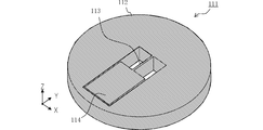
- FIG. 17 is a perspective view showing the configuration of the angular acceleration detection element 111 according to the twelfth embodiment.
- the angular acceleration detection element 111 includes a rotary weight 112, a support beam 113, a fixed portion 114, and a detection portion 115 (not shown).
- the rotary weight 112 has a circular outer shape. Even in the angular acceleration detecting element 111 having such a configuration, the rotating weight 112 rotates (swings) about the Z axis with respect to the fixed portion 114 in the XY plane by the action of the rotational inertia force about the Z axis. Angular acceleration can be detected using the Z axis as a detection axis.
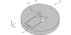
- FIG. 18 is a perspective view showing the configuration of the angular acceleration detection element 121 according to the thirteenth embodiment.
- the angular acceleration detection element 121 includes a rotary weight 122, a support beam 123, a fixing unit 124, and a detection unit 125 (not shown).
- the outer shape of the rotary weight 122 has a circular shape
- the support beam 123 has a shape that is narrow at the center and wide at both ends and has a semicircular side when viewed from the XY plane.
- the rotating weight 122 rotates (oscillates) around the Z axis with respect to the fixed portion 124 in the XY plane by the action of the rotational inertia force around the Z axis.
- Angular acceleration can be detected using the Z axis as a detection axis.
- FIG. 19 is a perspective view showing the configuration of the angular acceleration detection element 131 according to the fourteenth embodiment.
- the angular acceleration detection element 131 includes a rotary weight 132, a support beam 133, a fixed part 134, and a detection part 135 (not shown).
- the rotary weight 132 has an elliptical outer shape, the Y-axis direction is the long axis, and the X-axis direction is the short axis. Even in the angular acceleration detecting element 131 having such a configuration, the rotating weight 132 rotates (oscillates) around the Z axis with respect to the fixed portion 134 in the XY plane due to the rotational inertial force around the Z axis. Angular acceleration can be detected using the Z axis as a detection axis.
- FIG. 20 is a perspective view showing the configuration of the angular acceleration detection element 141 according to the fifteenth embodiment.
- the angular acceleration detection element 141 includes a rotary weight 142, a support beam 143, a fixed portion 144, and a detection portion 145 (not shown).
- the rotary weight 142 has a rectangular outer shape and includes a rectangular opening 142A. By providing the opening 142A, it becomes easy to adjust the position of the center of gravity of the rotary weight 142. Even in the angular acceleration detecting element 141 having such a configuration, the rotating weight 142 rotates (oscillates) around the Z axis with respect to the fixed portion 144 in the XY plane by the action of the rotational inertia force around the Z axis. Angular acceleration can be detected using the Z axis as a detection axis.
- FIG. 21 is a perspective view showing the configuration of the angular acceleration detection element 151 according to the sixteenth embodiment.
- the angular acceleration detection element 151 includes a rotating weight 152, a support beam 153, a fixed portion 154, an extraction electrode 155, and a detection portion 156 (not shown).
- the angular acceleration detection element 151 has a configuration in which the fixed portion 154 is disposed on the outer peripheral side and the rotary weight 152 is disposed on the inner side of the fixed portion 154.
- the fixed portion 154 has an outer shape viewed from the XY plane having a rectangular shape with a major axis in the Y-axis direction and a minor axis in the X-axis direction.
- the rotary weight 152 has a U-shape that is disposed in the opening of the fixed portion 154 in the XY plane and has an open X-axis positive direction.
- the support beam 153 is disposed at the position of the center of gravity of the rotary weight 152, and the Y-axis direction is the length direction and the X-axis direction is the width direction.
- the extraction electrode 155 is extracted from the support beam 153 to the upper surface of the fixed portion 154.
- the rotating weight 152 rotates (swings) around the Z axis with respect to the fixed portion 154 in the XY plane by the rotation inertia force around the Z axis, and the Z axis is detected.
- Angular acceleration can be detected as an axis.
- the outer periphery of the fixed portion 154 becomes a separation surface. Therefore, at the time of separation, the rotating weight 152 can be prevented from coming into contact with other members, and the support beam 153 can be prevented from being damaged due to excessive weight. Also, when the angular acceleration detection element is incorporated into another member, the rotating weight 152 can be prevented from coming into contact with the other member, and assembly can be facilitated.
- FIG. 22 is a diagram illustrating another configuration of the detection unit.
- the detection unit is composed of four piezoresistors 166A to 166D.
- the piezoresistors 166A and 166B are arranged in the negative direction of the X axis with respect to the neutral surface of the upper surface of the support beam 163.
- the piezoresistors 166C and 166D are arranged in the positive direction of the X axis with respect to the neutral surface of the upper surface of the support beam 163.
- the piezoresistors 166A and 166C are arranged on the Y axis negative direction side of the upper surface of the support beam 163, and the piezoresistors 166B and 166D are arranged on the Y axis positive direction side of the upper surface of the support beam 163.
- piezo resistors 166A to 166D constitute a bridge circuit.
- Piezoresistors 166A and 166B are provided on opposite sides of the four sides of the bridge circuit, and piezoresistors 166C and 166D are also provided on opposite sides of the four sides of the bridge circuit.
- Piezoresistors provided on the opposite side with the neutral plane of the support beam 163 as a boundary are connected in series, and two series circuits are connected in parallel to a constant voltage source or a constant current source. Wiring is performed so that the potentials of the bridge output terminals change with opposite polarities, and the potential difference can be measured as a voltage fluctuation.
- the bridge circuit By adopting the bridge circuit, a larger potential difference can be obtained with the same stress as compared with the case where angular acceleration is detected using the voltage division ratio as shown in the first embodiment.
- a bridge circuit it is possible to increase the common mode rejection ratio with respect to drive power supply noise, and to extract a minute electric signal with a good S / N ratio. For these reasons, detection sensitivity and detection accuracy of angular acceleration can be further increased.
- FIG. 23 is a perspective view showing a configuration of an angular acceleration detection element 171 according to the seventeenth embodiment.
- the angular acceleration detection element 171 includes a rotary weight 172, a support beam 173, a fixed part 174, an extraction electrode 175, and a detection part 176 (not shown). Similar to the sixteenth embodiment, the angular acceleration detection element 171 has a configuration in which the fixed portion 174 is disposed on the outer peripheral side and the rotary weight 172 is disposed on the inner side of the fixed portion 174. The main difference from the sixteenth embodiment is the arrangement position of the extraction electrode 175.
- the angular acceleration detection element 171 When the angular acceleration detection element 171 is housed in the housing, it is necessary to read an electrical signal from the extraction electrode 175 connected to the piezoresistor. However, the distance between the extraction electrodes 175 is a certain length or more due to the restrictions on the housing processing. There is a need.
- two of the four extraction electrodes 175 are drawn out to the opposite side across the rotating weight 172 of the fixed portion 174, thereby suppressing the area required for forming the extraction electrode, A large moment of inertia of the rotary weight 172 can be ensured, and as a result, a decrease in angular acceleration detection sensitivity can be suppressed.
- FIG. 24 is a diagram illustrating another configuration of the detection unit.
- This detection unit constitutes a bridge circuit by four piezoresistors 186A to 186D.
- the piezoresistors 186A and 186B are arranged in the X-axis negative direction and parallel to the Y-axis with respect to the neutral surface of the upper surface of the support beam 183.
- the piezoresistors 186C and 186D are arranged in parallel to the Y axis in the positive direction of the X axis from the neutral surface of the upper surface of the support beam 183.
- the piezoresistors 186A to 186D are arranged, the piezoresistors provided on the opposite side with the neutral surface of the support beam 183 as a boundary are connected in series, and two series circuits are connected to a constant voltage source or a constant current. By connecting in parallel to the source, wiring can be performed so that the potentials of the bridge output terminals change with opposite polarities due to the stress of the support beam 183, and the potential difference can be measured as a voltage fluctuation.
- FIG. 25 is a diagram illustrating the configuration of the angular acceleration detection element 191 according to the eighteenth embodiment.
- the angular acceleration detection element 191 of this embodiment is configured to detect angular acceleration around the X axis, as in the second embodiment.
- a bridge circuit is configured by the four piezoresistors 196A to 196D.
- the piezoresistors 196A and 196B are disposed on the lower surface of the support beam 193.
- the piezoresistors 196C and 196D are disposed on the upper surface of the support beam 193.
- piezoresistors 196A to 196D are arranged in this way, two piezoresistors provided on the opposite side with the neutral surface (parallel to the XY plane) of the support beam 193 as a boundary are connected in series. Is connected in parallel to a constant voltage source or a constant current source so that the potentials of the bridge output terminals change with opposite polarities due to the stress of the support beam 193, and the potential difference is measured as a voltage fluctuation. Can do.
- the present invention can be implemented in various forms. At least the center of gravity of the rotary weight overlaps with the support beam, or the configuration overlaps with the neutral surface of the support beam.
- the invention can be suitably implemented.
Landscapes
- Physics & Mathematics (AREA)
- General Physics & Mathematics (AREA)
- Engineering & Computer Science (AREA)
- Radar, Positioning & Navigation (AREA)
- Remote Sensing (AREA)
- Pressure Sensors (AREA)
- Investigating Strength Of Materials By Application Of Mechanical Stress (AREA)
Abstract
Description
このような角加速度検出素子において、回転錘の検出軸回りでの回転バランスが崩れていれば、並進慣性力によっても回転錘が回転してしまう。すると、並進慣性力が検出信号のノイズ要因となり、検出軸回りでの角加速度の検出精度が低下する。
この構成では、回転錘の重心位置に重なる単一の支持梁のみで回転錘の回転バランスを取ることができる。
この構成では、複数の支持梁それぞれに作用する応力の中立面が一致するため、複数の支持梁の総体としての応力分布が、単一の支持梁による応力分布と実質的に等価なものになる。このため、実質的に単一の支持梁のみで回転錘の回転バランスを取ることができる。
この構成では、検出軸回りでの回転錘の慣性モーメントが大きくなるため、角加速度あたりの回転慣性力を大きくすることができる。すると、固有振動数を保つために必要な支持梁の幅が太くなるとともに支持梁の長さが短くなる。このことが角加速度の検出感度を高めることに寄与する。
この構成では、検出軸回りでの回転錘の慣性モーメントがさらに大きくなるため、角加速度あたりの回転慣性力をより大きくすることができる。このため、同じ角加速度検出感度を得るために必要な素子占有面積を低減でき、低コスト化や小型化を進展させることができる。
この構成の回転錘は短軸回りの慣性モーメントが大きく、外乱振動による短軸回りの回転慣性力が大きくなってしまう。そのため、回転錘の短軸方向が支持梁の長さ方向であれば、短軸回りの回転慣性力により支持梁が捻れ、支持梁のエッジ部分に過大な応力集中が生じて耐衝撃性能が低下してしまう。そこで、上述のように支持梁の長さ方向を回転錘の長軸方向とすることで、短軸回りの回転慣性力によって支持梁が捻れることを防ぎ、支持梁のエッジ部分への応力集中を回避できる。
図1(A)は本発明の第1の実施形態に係る角加速度検出素子1の構成を示す斜視図であり、図1(B)は角加速度検出素子1の平面図である。
この場合、回転錘2は、固定部4を基準としてZ軸正方向から視て反時計回りに回転し、支持梁3にはZ軸正方向から視て反時計回りの回転慣性力が作用する。これにより、支持梁3は、X軸負方向の側面近傍の領域に圧縮応力が作用し、X軸正方向の側面近傍の領域に引っ張り応力が作用し、X軸負方向に撓むことになる。支持梁3の幅方向の中心面(一点鎖線で図示する。)が引っ張り応力と圧縮応力との境となり応力が作用しない中立面であり、X-Y面で視てこの中心面上に回転錘2の重心位置(×で図示する。)が重なることになる。
検出部5は、支持梁3の上面にY軸方向を長手とするピエゾ抵抗5A,5Bを備える。ピエゾ抵抗5A,5Bは、半導体ウェハに半導体プロセスを用いて形成されることにより、微細な位置・形状を高精度にすることが可能である。これらのピエゾ抵抗5A,5Bは、支持梁3の中立面の両側に平行に配置され、互いに直列接続され定電圧源に接続される。支持梁3の中立面を境に一方の領域は圧縮応力が作用し、他方の領域は引っ張り応力が作用するため、ピエゾ抵抗5A,5Bは伸縮が逆になる。ピエゾ抵抗5A,5Bは伸長する際には抵抗値が増大し、短縮する際には抵抗値が低減する。そのため、ピエゾ抵抗5A,5Bによる分圧比が変動するため、ピエゾ抵抗5Aやピエゾ抵抗5Bの両端電圧から、支持梁3に作用する応力を検出することが可能になる。
図5(A)は比較構成に係る角加速度検出素子10Aの構成を示す平面図である。角加速度検出素子10Aは、2つの支持梁を備え、回転錘の重心位置を中心に対称な形状で構成している。
図5(B)は比較構成に係る角加速度検出素子10Bの構成を示す平面図である。角加速度検出素子10Bは、4つの支持梁を備え、回転錘の重心位置を中心に対称な形状で構成している。
これら構成の解析例では、実施形態に係る角加速度検出素子1とともに同じ外形寸法2mm×2mm×200μmとし、回転錘2および固定部4を同形状とし、支持梁の寸法調整により固有振動数f0を2.0kHzで一致させた。
実施形態に係る角加速度検出素子1は、支持梁の数nが1、支持梁の長さ(Y軸方向寸法)Lyが110μm、支持梁の幅(X軸方向寸法)Lxが20μmであり、これにより固有振動数f0を2.0kHzとしている。
比較構成に係る角加速度検出素子10Aは、支持梁の数nが2、支持梁の長さ(Y軸方向寸法)Lyが441μm、支持梁の幅(X軸方向寸法)Lxが10μmであり、これにより固有振動数f0を2.0kHzとしている。
比較構成に係る角加速度検出素子10Bは、支持梁の数nが4、支持梁の長さ(Y軸方向寸法)Lyが640μm、支持梁の幅(X軸方向寸法)Lxが10μmであり、これにより固有振動数f0を2.0kHzとしている。
図6(A)は、本発明の第2の実施形態に係る角加速度検出素子11の変形状態での斜視図である。図6(B)は、角加速度検出素子11の支持梁13の周辺構造を示す模式図である。
この場合、回転錘12は、固定部14を基準としてX軸正方向から視て時計回りに回転し、支持梁13にはX軸正方向から視て時計回りの回転慣性力が作用する。これにより、支持梁13は、Z軸正方向の上面近傍の領域に圧縮応力が作用し、Z軸負方向の下面近傍の領域に引っ張り応力が作用し、支持梁13はZ軸正方向に撓むことになる。
図8は、第3の実施形態に係る角加速度検出素子91の構成を示す斜視図である。
また、回転錘92がX軸方向を長軸とする形状であるため、Z軸回りでの慣性モーメントが大きく、回転錘の外形が正方形状である場合などよりも、同じ素子専有面積で、角加速度あたりの回転慣性力を大きくすることができる。
そのため、角加速度検出素子91の固有振動数を維持したまま支持梁93を太く短くすることが可能であり、角加速度検出感度を高めることができる。
図9(A)は、第4の実施形態に係る角加速度検出素子21の斜視図である。
角加速度検出素子21は、Z軸に垂直な上下面間を貫通する溝を形成した長方形板からなり、回転錘22、支持梁23、固定部24、および検出部25(不図示)を備える。回転錘22はX軸正方向が開いたコの字状であり、Y軸方向を長軸としX軸方向を短軸とする。支持梁23は、回転錘22の重心位置に中心が一致し、Y軸方向を長さ方向、X軸方向を幅方向とする。固定部24は、回転錘22の開口内に設けられて図示しない筐体に上面と下面との少なくとも一方で固定され、支持梁23を介して回転錘22を支持する。
この場合、回転錘22は、固定部24を基準としてZ軸正方向から視て反時計回りに回転し、支持梁23にはZ軸正方向から視て反時計回りの回転慣性力が作用する。これにより、支持梁23は、X軸負方向の側面近傍の領域に圧縮応力が作用し、X軸正方向の側面近傍の領域に引っ張り応力が作用し、X軸負方向に撓むことになる。
そのため、角加速度検出素子21の固有振動数を維持したまま支持梁を太く短くすることが可能になり、角加速度検出感度を高めることができる。
図10は、第5の実施形態に係る角加速度検出素子31における、回転慣性力が作用する場合の応力分布を説明する図である。
図11は、第6の実施形態に係る角加速度検出素子41における、回転慣性力が作用する場合の応力分布を説明する図である。
図12は、第7の実施形態に係る角加速度検出素子51における、回転慣性力が作用する場合の応力分布を説明する図である。
図13は、第8の実施形態に係る角加速度検出素子61における、回転慣性力が作用する場合の応力分布を説明する図である。
図14は、第9の実施形態に係る角加速度検出素子71の部分拡大斜視図である。
図15(A)は、第10の実施形態に係る角加速度検出素子81の斜視図である。
角加速度検出素子81は、第4の実施形態の構成を2つ突き合わせて回転錘を一体化したような構成であり、回転錘82、支持梁83、固定部84、および検出部85(不図示)を備える。回転錘82は開口を備えるロの字状であり、Y軸方向を長軸としX軸方向を短軸とする。回転錘82の開口内には2つの支持梁83と2つの固定部84とが配置される。2つの支持梁83は、回転錘82の重心を隔てて平行に設けられる。2つの固定部84は、図示しない筐体に上面と下面との少なくとも一方で固定され、それぞれ支持梁83を介して回転錘82を支持する。
この場合、回転錘82は、固定部84を基準としてZ軸正方向から視て反時計回りに回転し、支持梁83にはZ軸正方向から視て反時計回りの回転慣性力が作用する。これにより、X軸負方向側の支持梁83は圧縮応力が作用し、X軸正方向の支持梁83は引っ張り応力が作用し、2つの支持梁83はX軸負方向に撓むことになる。
図16は、第11の実施形態に係る角加速度検出素子101の構成を示す斜視図である。
図17は、第12の実施形態に係る角加速度検出素子111の構成を示す斜視図である。
図18は、第13の実施形態に係る角加速度検出素子121の構成を示す斜視図である。
図19は、第14の実施形態に係る角加速度検出素子131の構成を示す斜視図である。
図20は、第15の実施形態に係る角加速度検出素子141の構成を示す斜視図である。
図21は、第16の実施形態に係る角加速度検出素子151の構成を示す斜視図である。
図23は、第17の実施形態に係る角加速度検出素子171の構成を示す斜視図である。
図25は、第18の実施形態に係る角加速度検出素子191の構成を説明する図である。本実施形態の角加速度検出素子191は、第2の実施形態と同様に、X軸回りの角加速度を検出する構成である。
2…回転錘
3…支持梁
4…固定部
5…検出部
73A,102A,102B…突起部
Claims (11)
- 所定の検出軸回り角加速度による慣性力の作用で前記検出軸回りに回転する回転錘と、
前記回転錘から離間する位置に設けられた固定部と、
前記検出軸に対する直交面における前記固定部と前記回転錘との間に設けられ、前記固定部に対して前記回転錘を弾性支持する支持梁と、
前記支持梁に発生した応力に応じた検出信号を出力する検出部と、を備え、
前記検出軸方向から視た前記回転錘の重心位置が前記支持梁に重なるものである、角加速度検出素子。 - 所定の検出軸回りの角加速度による慣性力の作用で前記検出軸回りに回転する回転錘と、
前記回転錘から離間する位置に設けられた固定部と、
前記検出軸に対する直交面における前記固定部と前記回転錘との間に設けられ、前記固定部に対して前記回転錘を弾性支持する複数の支持梁と、
前記複数の支持梁に発生した応力に応じた検出信号を出力する検出部と、を備え、
前記検出軸方向から視た前記回転錘の重心位置が、前記検出軸回りでの前記回転錘の回転に伴って前記複数の支持梁に作用する応力の中立面に重なるものである、角加速度検出素子。 - 前記回転錘は、前記直交面に沿う長軸方向と短軸方向とを持つ形状で構成される、請求項1または2に記載の角加速度検出素子。
- 前記支持梁または前記複数の支持梁は、前記回転錘の長軸方向を長さ方向として構成される、請求項3に記載の角加速度検出素子。
- 前記固定部は、前記支持梁または前記複数の支持梁および前記回転錘を内装する開口を備える、請求項1~4のいずれかに記載の角加速度検出素子。
- 前記検出部は、前記支持梁または前記複数の支持梁に作用する応力に応じた検出信号を出力する素子を四辺に設けたブリッジ回路を備え、前記ブリッジ回路の隣接する辺の素子が前記支持梁または前記複数の支持梁の中立面に対して異なる側に設けられる、請求項1~5のいずれかに記載の角加速度検出素子。
- 前記検出部は、前記支持梁または前記複数の支持梁に作用する応力に応じて抵抗値が変化する抵抗素子で構成される、請求項1~6のいずれかに記載の角加速度検出素子。
- 前記支持梁または前記複数の支持梁と前記固定部と前記回転錘とは、同一の薄板状部材から加工形成される、請求項1~7のいずれかに記載の角加速度検出素子。
- 前記薄板状部材が半導体ウェハで構成される、請求項8に記載の角加速度検出素子。
- 前記回転錘の前記検出軸は、前記薄板状部材の厚み方向に構成される、請求項8または9に記載の角加速度検出素子。
- 前記支持梁または前記複数の支持梁は、前記薄板状部材の厚み方向に前記回転錘よりも突出する突起部を備える、請求項10に記載の角加速度検出素子。
Priority Applications (4)
| Application Number | Priority Date | Filing Date | Title |
|---|---|---|---|
| CN201180070708.9A CN103534597B (zh) | 2011-05-12 | 2011-12-16 | 角加速度检测元件 |
| EP11865192.6A EP2708903A4 (en) | 2011-05-12 | 2011-12-16 | ANGULAR ACCELERATION DETECTOR ELEMENT |
| JP2013513899A JP5618002B2 (ja) | 2011-05-12 | 2011-12-16 | 角加速度検出素子 |
| US14/064,371 US9983003B2 (en) | 2011-05-12 | 2013-10-28 | Angular acceleration detection device |
Applications Claiming Priority (2)
| Application Number | Priority Date | Filing Date | Title |
|---|---|---|---|
| JP2011107338 | 2011-05-12 | ||
| JP2011-107338 | 2011-05-12 |
Related Child Applications (1)
| Application Number | Title | Priority Date | Filing Date |
|---|---|---|---|
| US14/064,371 Continuation US9983003B2 (en) | 2011-05-12 | 2013-10-28 | Angular acceleration detection device |
Publications (1)
| Publication Number | Publication Date |
|---|---|
| WO2012153439A1 true WO2012153439A1 (ja) | 2012-11-15 |
Family
ID=47138933
Family Applications (1)
| Application Number | Title | Priority Date | Filing Date |
|---|---|---|---|
| PCT/JP2011/079139 WO2012153439A1 (ja) | 2011-05-12 | 2011-12-16 | 角加速度検出素子 |
Country Status (5)
| Country | Link |
|---|---|
| US (1) | US9983003B2 (ja) |
| EP (1) | EP2708903A4 (ja) |
| JP (1) | JP5618002B2 (ja) |
| CN (1) | CN103534597B (ja) |
| WO (1) | WO2012153439A1 (ja) |
Cited By (5)
| Publication number | Priority date | Publication date | Assignee | Title |
|---|---|---|---|---|
| WO2014092040A1 (ja) * | 2012-12-13 | 2014-06-19 | 株式会社村田製作所 | 角加速度センサおよび加速度センサ |
| WO2014092039A1 (ja) * | 2012-12-13 | 2014-06-19 | 株式会社村田製作所 | 角加速度センサおよび加速度センサ |
| JP6010678B1 (ja) * | 2015-11-24 | 2016-10-19 | 株式会社トライフォース・マネジメント | 加速度センサ |
| JP6020590B2 (ja) * | 2012-11-19 | 2016-11-02 | 株式会社村田製作所 | 角加速度センサ |
| JP6058858B1 (ja) * | 2016-09-16 | 2017-01-11 | 株式会社トライフォース・マネジメント | 加速度センサ |
Families Citing this family (1)
| Publication number | Priority date | Publication date | Assignee | Title |
|---|---|---|---|---|
| US11796318B2 (en) | 2021-08-18 | 2023-10-24 | Honeywell International Inc. | Rotation measurement system using Coriolis and Euler forces |
Citations (5)
| Publication number | Priority date | Publication date | Assignee | Title |
|---|---|---|---|---|
| JPH0421970U (ja) * | 1990-06-18 | 1992-02-24 | ||
| JP2602300B2 (ja) | 1988-09-30 | 1997-04-23 | 日本電気株式会社 | 半導体センサ |
| JP2010139263A (ja) | 2008-12-09 | 2010-06-24 | Murata Mfg Co Ltd | 角加速度センサ |
| JP2011033617A (ja) * | 2009-07-10 | 2011-02-17 | Yamaha Corp | 1軸加速度センサ |
| JP2011117944A (ja) * | 2009-10-29 | 2011-06-16 | Seiko Epson Corp | 加速度センサー |
Family Cites Families (9)
| Publication number | Priority date | Publication date | Assignee | Title |
|---|---|---|---|---|
| US5101669A (en) * | 1988-07-14 | 1992-04-07 | University Of Hawaii | Multidimensional force sensor |
| US6718605B2 (en) * | 1997-09-08 | 2004-04-13 | The Regents Of The University Of Michigan | Single-side microelectromechanical capacitive accelerometer and method of making same |
| DE69938658D1 (de) * | 1999-09-10 | 2008-06-19 | St Microelectronics Srl | Gegen mechanische Spannungen unempfindliche mikroelektromechanische Struktur |
| US6938484B2 (en) * | 2003-01-16 | 2005-09-06 | The Regents Of The University Of Michigan | Micromachined capacitive lateral accelerometer device and monolithic, three-axis accelerometer having same |
| JP2005227591A (ja) * | 2004-02-13 | 2005-08-25 | Murata Mfg Co Ltd | 静電型アクチュエータ |
| JP2007285879A (ja) | 2006-04-17 | 2007-11-01 | Seiko Epson Corp | 角速度センサおよびその製造方法 |
| JP2007322200A (ja) * | 2006-05-31 | 2007-12-13 | Kyocera Kinseki Corp | 慣性センサ素子 |
| DE102009002066A1 (de) * | 2009-03-31 | 2010-10-07 | Sensordynamics Ag | Verfahren zum Erfassen von Beschleunigungen und Drehraten sowie MEMS-Sensor |
| FR2944102B1 (fr) * | 2009-04-03 | 2011-06-10 | Onera (Off Nat Aerospatiale) | Element vibrant sur deux modes decouples et application a un gyrometre vibrant. |
-
2011
- 2011-12-16 WO PCT/JP2011/079139 patent/WO2012153439A1/ja active Application Filing
- 2011-12-16 CN CN201180070708.9A patent/CN103534597B/zh active Active
- 2011-12-16 JP JP2013513899A patent/JP5618002B2/ja not_active Expired - Fee Related
- 2011-12-16 EP EP11865192.6A patent/EP2708903A4/en not_active Withdrawn
-
2013
- 2013-10-28 US US14/064,371 patent/US9983003B2/en active Active
Patent Citations (5)
| Publication number | Priority date | Publication date | Assignee | Title |
|---|---|---|---|---|
| JP2602300B2 (ja) | 1988-09-30 | 1997-04-23 | 日本電気株式会社 | 半導体センサ |
| JPH0421970U (ja) * | 1990-06-18 | 1992-02-24 | ||
| JP2010139263A (ja) | 2008-12-09 | 2010-06-24 | Murata Mfg Co Ltd | 角加速度センサ |
| JP2011033617A (ja) * | 2009-07-10 | 2011-02-17 | Yamaha Corp | 1軸加速度センサ |
| JP2011117944A (ja) * | 2009-10-29 | 2011-06-16 | Seiko Epson Corp | 加速度センサー |
Non-Patent Citations (1)
| Title |
|---|
| See also references of EP2708903A4 |
Cited By (11)
| Publication number | Priority date | Publication date | Assignee | Title |
|---|---|---|---|---|
| JP6020590B2 (ja) * | 2012-11-19 | 2016-11-02 | 株式会社村田製作所 | 角加速度センサ |
| WO2014092040A1 (ja) * | 2012-12-13 | 2014-06-19 | 株式会社村田製作所 | 角加速度センサおよび加速度センサ |
| WO2014092039A1 (ja) * | 2012-12-13 | 2014-06-19 | 株式会社村田製作所 | 角加速度センサおよび加速度センサ |
| CN104838275A (zh) * | 2012-12-13 | 2015-08-12 | 株式会社村田制作所 | 角加速度传感器以及加速度传感器 |
| CN104838274A (zh) * | 2012-12-13 | 2015-08-12 | 株式会社村田制作所 | 角加速度传感器以及加速度传感器 |
| JPWO2014092040A1 (ja) * | 2012-12-13 | 2017-01-12 | 株式会社村田製作所 | 角加速度センサおよび加速度センサ |
| JPWO2014092039A1 (ja) * | 2012-12-13 | 2017-01-12 | 株式会社村田製作所 | 角加速度センサおよび加速度センサ |
| US9682853B2 (en) | 2012-12-13 | 2017-06-20 | Murata Manufacturing Co., Ltd. | Angular acceleration sensor and acceleration sensor |
| US9726690B2 (en) | 2012-12-13 | 2017-08-08 | Murata Manufacturing Co., Ltd. | Angular acceleration sensor and acceleration sensor |
| JP6010678B1 (ja) * | 2015-11-24 | 2016-10-19 | 株式会社トライフォース・マネジメント | 加速度センサ |
| JP6058858B1 (ja) * | 2016-09-16 | 2017-01-11 | 株式会社トライフォース・マネジメント | 加速度センサ |
Also Published As
| Publication number | Publication date |
|---|---|
| US20140047919A1 (en) | 2014-02-20 |
| JP5618002B2 (ja) | 2014-11-05 |
| US9983003B2 (en) | 2018-05-29 |
| EP2708903A1 (en) | 2014-03-19 |
| EP2708903A4 (en) | 2014-10-22 |
| CN103534597B (zh) | 2015-11-25 |
| CN103534597A (zh) | 2014-01-22 |
| JPWO2012153439A1 (ja) | 2014-07-28 |
Similar Documents
| Publication | Publication Date | Title |
|---|---|---|
| JP5618002B2 (ja) | 角加速度検出素子 | |
| JP3956999B2 (ja) | 加速度センサ | |
| CN112703406B (zh) | 灵敏度提高的z-轴加速度计 | |
| WO2013179647A2 (ja) | 物理量センサ | |
| JPWO2005062060A1 (ja) | 半導体型3軸加速度センサ | |
| JP6258051B2 (ja) | 角速度センサ、センサ素子及びセンサ素子の製造方法 | |
| WO2018021167A1 (ja) | 角速度センサ、センサ素子および多軸角速度センサ | |
| JP5205619B2 (ja) | 圧電落下センサ及び圧電落下センサを用いた落下検出方法 | |
| JP2016133428A (ja) | センサ素子及び角速度センサ | |
| JP2013246033A (ja) | 加速度センサ | |
| WO2013027741A1 (ja) | 圧電振動センサ | |
| WO2019021860A1 (ja) | センサ素子および角速度センサ | |
| JP4637074B2 (ja) | ピエゾ抵抗型加速度センサー | |
| JP6065017B2 (ja) | 角加速度センサおよび加速度センサ | |
| JP2007101203A (ja) | 角速度センサ | |
| JP2008107300A (ja) | 加速度センサ | |
| JP6517507B2 (ja) | センサ素子及び角速度センサ | |
| JP5971349B2 (ja) | 角加速度センサ | |
| JP4466344B2 (ja) | 加速度センサ | |
| JP6020590B2 (ja) | 角加速度センサ | |
| JP2009264863A (ja) | ジャイロセンサ振動体 | |
| JP2007199081A (ja) | 加速度センサ | |
| JP2017058353A (ja) | センサ素子 | |
| WO2012086103A1 (ja) | 加速度センサ | |
| JP6294463B2 (ja) | センサ |
Legal Events
| Date | Code | Title | Description |
|---|---|---|---|
| 121 | Ep: the epo has been informed by wipo that ep was designated in this application |
Ref document number: 11865192 Country of ref document: EP Kind code of ref document: A1 |
|
| ENP | Entry into the national phase |
Ref document number: 2013513899 Country of ref document: JP Kind code of ref document: A |
|
| REEP | Request for entry into the european phase |
Ref document number: 2011865192 Country of ref document: EP |
|
| WWE | Wipo information: entry into national phase |
Ref document number: 2011865192 Country of ref document: EP |
|
| NENP | Non-entry into the national phase |
Ref country code: DE |