WO2012147547A1 - 車両のバンパー構造 - Google Patents
車両のバンパー構造 Download PDFInfo
- Publication number
- WO2012147547A1 WO2012147547A1 PCT/JP2012/060228 JP2012060228W WO2012147547A1 WO 2012147547 A1 WO2012147547 A1 WO 2012147547A1 JP 2012060228 W JP2012060228 W JP 2012060228W WO 2012147547 A1 WO2012147547 A1 WO 2012147547A1
- Authority
- WO
- WIPO (PCT)
- Prior art keywords
- sheet metal
- vehicle
- bumper
- spoiler
- resin
- Prior art date
- Legal status (The legal status is an assumption and is not a legal conclusion. Google has not performed a legal analysis and makes no representation as to the accuracy of the status listed.)
- Ceased
Links
Images



Classifications
-
- B—PERFORMING OPERATIONS; TRANSPORTING
- B60—VEHICLES IN GENERAL
- B60R—VEHICLES, VEHICLE FITTINGS, OR VEHICLE PARTS, NOT OTHERWISE PROVIDED FOR
- B60R19/00—Wheel guards; Radiator guards, e.g. grilles; Obstruction removers; Fittings damping bouncing force in collisions
- B60R19/52—Radiator or grille guards ; Radiator grilles
-
- B—PERFORMING OPERATIONS; TRANSPORTING
- B60—VEHICLES IN GENERAL
- B60R—VEHICLES, VEHICLE FITTINGS, OR VEHICLE PARTS, NOT OTHERWISE PROVIDED FOR
- B60R19/00—Wheel guards; Radiator guards, e.g. grilles; Obstruction removers; Fittings damping bouncing force in collisions
- B60R19/02—Bumpers, i.e. impact receiving or absorbing members for protecting vehicles or fending off blows from other vehicles or objects
- B60R19/24—Arrangements for mounting bumpers on vehicles
-
- B—PERFORMING OPERATIONS; TRANSPORTING
- B60—VEHICLES IN GENERAL
- B60R—VEHICLES, VEHICLE FITTINGS, OR VEHICLE PARTS, NOT OTHERWISE PROVIDED FOR
- B60R19/00—Wheel guards; Radiator guards, e.g. grilles; Obstruction removers; Fittings damping bouncing force in collisions
- B60R19/02—Bumpers, i.e. impact receiving or absorbing members for protecting vehicles or fending off blows from other vehicles or objects
- B60R19/04—Bumpers, i.e. impact receiving or absorbing members for protecting vehicles or fending off blows from other vehicles or objects formed from more than one section in a side-by-side arrangement
-
- B—PERFORMING OPERATIONS; TRANSPORTING
- B60—VEHICLES IN GENERAL
- B60R—VEHICLES, VEHICLE FITTINGS, OR VEHICLE PARTS, NOT OTHERWISE PROVIDED FOR
- B60R19/00—Wheel guards; Radiator guards, e.g. grilles; Obstruction removers; Fittings damping bouncing force in collisions
- B60R19/52—Radiator or grille guards ; Radiator grilles
- B60R2019/525—Radiator grilles
- B60R2019/527—Radiator grilles integral with bumpers
Definitions
- the present invention relates to a bumper structure of a vehicle.
- the front end portion of the vehicle is disposed such that the lower front bumper lower portion around the upper front hood (bonnet) is protruded toward the front side of the vehicle.
- the upper part of the pedestrian's leg tends to move backward and the leg tends to tilt. It was. If the pedestrian's leg is inclining and bites into the front bumper, the load from the front side of the vehicle tends to cause bending and shear stress on the pedestrian's leg, and the load on the leg ( Obstacle value) tended to increase.
- the leg can be kept straight.
- some conventional vehicle bumpers employ a structure that supports the lower end of the pedestrian's legs by providing a reinforcement or absorber on the back side of the bumper fascia (for example, see Patent Document 1).
- the leg part of a pedestrian is less likely to bend along the inclined part of the front part of the vehicle, and the leg part is held substantially linearly.
- produce bending stress and shear stress in a leg part a leg part is protected.
- a reinforcement is provided in addition to the body frame for the purpose of increasing the rigidity near the lower end of the bumper, so that the number of parts increases and the productivity decreases. was there.
- the absorber is provided.
- the absorber is provided.
- the moldability of the bumper is deteriorated, and a gap or a step with other peripheral parts due to insufficient accuracy is generated and the appearance quality is deteriorated. There is a possibility that it may cause a decrease in productivity and an increase in cost.
- the present invention has been made in view of such a situation, and the object thereof is not to have a complicated configuration, but has both a load absorbing portion and a high-rigidity portion, and the lower part of the bumper impairs the moldability.
- the deformation of the lower part of the bumper is minimized, and the load is smoothly transmitted to the vehicle body frame so that the pedestrian's leg hits the bumper.
- An object of the present invention is to provide a vehicle bumper structure capable of efficiently absorbing a load and more reliably reducing leg bending.
- a resin spoiler extending in the vehicle width direction is provided in front of a lower portion of a bumper, and a sheet metal member having a shape along the spoiler shape is integrally formed with the resin spoiler.
- the main part of the sheet metal member is covered by the resin spoiler, and the rear part of the resin spoiler and the sheet metal member extends toward the rear of the vehicle. Only the resin spoiler and the sheet metal member or the sheet metal member extending rearward are attached to the vehicle body frame.
- board thickness of the back side sheet-metal part extended toward a vehicle back among the said sheet-metal members is set thicker than the front side sheet-metal part, and the said resin spoiler is provided in the back surface side of the said resin spoiler.
- a boss for attaching to the bumper is provided, and the position of the boss is overlapped with the thicker rear side sheet metal part in the vehicle vertical direction.
- a part of the sheet metal member is configured as a tailored blank part by joining the thin sheet metal front side sheet metal part and the sheet metal thick rear side sheet metal part, at least, The front side sheet metal part and the tailored blank part are covered with the resin spoiler.
- a resin spoiler extending in the vehicle width direction is provided in front of the lower portion of the bumper, and a sheet metal member having a shape along the spoiler shape is integrally bonded and pasted to the back surface of the resin spoiler.
- the resin spoiler and the rear portion of the sheet metal member extend toward the rear of the vehicle, the sheet metal member extending toward the rear of the vehicle is attached to a vehicle body frame, and among the sheet metal members
- the sheet thickness of the rear side sheet metal part extending toward the rear of the vehicle is set to be thicker than that of the front side sheet metal part.
- a part of said sheet-metal member is comprised as a tailored blank part by joining the said sheet
- the front end of the buffer structure provided in the body frame is the same as the position of the boundary between the thin sheet metal front portion and the thick sheet metal rear portion in the vehicle side view. Placed in position.
- the resin spoiler extending in the vehicle width direction is provided in front of the lower portion of the bumper, and a sheet metal member having a shape along the spoiler shape is integrally joined to the resin spoiler.
- the main part of the sheet metal member is covered with the resin spoiler, and the rear part of the resin spoiler and the sheet metal member extends toward the rear of the vehicle and extends toward the rear of the vehicle. Since only the resin spoiler and the sheet metal member, or only the sheet metal member are attached to the vehicle body frame, the load spouting portion and the high rigidity portion are combined with a relatively simple configuration of the resin spoiler and the sheet metal member. Is possible.
- the rigidity of the lower part of the bumper is improved, and the sheet metal member is integrally joined to the vehicle body frame, so that deformation of the fixed part of the bumper due to vibration during traveling of the vehicle can be reduced.
- the load from the leg is quickly and reliably transmitted from the bumper to the body frame while minimizing deformation of the lower part of the bumper. can do.
- the resin spoiler and the sheet metal member are integrated and no clearance is provided between them, the load absorbing function can be started from the time when the leg of the pedestrian hits.
- the bumper structure of the present invention when the pedestrian's leg hits the bumper at the time of a collision, the load on the leg can be efficiently absorbed, the bending of the leg is reduced, The burden can be reduced more reliably.
- the lower part of the bumper is not shaped to protrude forward of the vehicle, and the resin spoiler protrudes forward of the vehicle, so that the moldability of the bumper is not impaired and gaps or steps with other peripheral parts due to insufficient accuracy are generated.
- the appearance quality can be improved, and the productivity can be improved and the cost can be reduced.
- the sheet thickness of the rear side sheet metal part extending toward the rear of the vehicle among the sheet metal members is set to be thicker than that of the front side sheet metal part. It is possible to cope with the situation where the rigidity to support and the rigidity necessary to absorb the initial load are different, and it is possible to achieve both of the two functions of load absorption from the front of the vehicle and support of the legs. The amount of movement toward the rear of the vehicle can be controlled so as to keep the legs of the vehicle straight.
- a boss for attaching the resin spoiler to the bumper is provided on the back surface side of the resin spoiler, and the position of the boss overlaps with the thick rear plate portion in the vehicle vertical direction.
- the bumper, the resin spoiler, and the vehicle body frame can be connected by the thick sheet metal portion on the rear side, and the bumper and the resin spoiler can be securely fixed to the vehicle body.
- a part of the sheet metal member is configured as a tailored blank part by joining the thin sheet metal front side sheet metal part and the sheet metal thick rear side sheet metal part.
- the dimensions of the spoiler shape can be easily secured by integrating the plates by press molding.
- since at least the front side metal plate portion and the tailored blank portion are covered with the resin spoiler since at least the front side metal plate portion and the tailored blank portion are covered with the resin spoiler, a step due to joining does not come out to the outside, and rainwater and mud accumulate in the step portion. Further, it is possible to avoid a situation where rust is generated at the stepped portion, and it is possible to improve the appearance quality.
- a resin spoiler extending in the vehicle width direction is provided in front of the lower portion of the bumper, and a sheet metal member having a shape along the spoiler shape is integrally joined to the back surface of the resin spoiler.
- the rear part of the resin spoiler and the sheet metal member extends toward the rear of the vehicle, and the sheet metal member that extends toward the rear of the vehicle is attached to a vehicle body frame, And since the plate
- a part of the sheet metal member is configured as a tailored blank portion by joining the thin sheet metal front side sheet metal part and the sheet metal thick rear side sheet metal part. It is possible to easily secure the dimensions of the spoiler shape by integrating by press molding of the joining plate.
- the front end of the buffer structure provided in the vehicle body frame has a boundary between the thin sheet metal front side sheet metal part and the thick sheet metal rear side sheet metal part and the vehicle side view.
- the deformation can be controlled by both members.
- the deformation of the thick sheet metal portion located on the vehicle rear side and the deformation of the buffer structure portion are completed, the lower end of the leg portion can be supported by the body frame having the highest rigidity. Therefore, in the structure of the present invention, by controlling the deformation of the sheet metal member and the buffer structure portion, it becomes possible to support the pedestrian's legs in a straight line and efficiently absorb the load by the legs. it can.
- FIG. 1 is a perspective view showing an appearance of a vehicle front portion to which a bumper structure according to an embodiment of the present invention is applied.
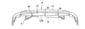
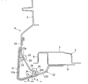
- FIG. 2 is a side sectional view showing a front bumper, spoiler, and peripheral components in the front part of the vehicle in FIG. 1. It is the bottom view which looked at the front bumper in Drawing 1 from the vehicles lower part.
- FIG. 3 is a side sectional view showing an X portion in FIG. 2 in an enlarged manner.
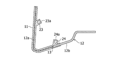
- FIG. 3 is an enlarged side sectional view showing a resin spoiler and a sheet metal member at the lower part of the front bumper in FIG. 2. It is the bottom view which looked at the front bumper of the vehicles to which the bumper structure concerning the modification of the embodiment of the present invention was applied from the vehicles lower part.
- FIG. 1 to 5 show a vehicle bumper structure according to an embodiment of the present invention.
- the vehicle front portion 1 to which the bumper structure according to the embodiment of the present invention is applied mainly extends along the vehicle front-rear direction and on both the left and right sides in the vehicle width direction.
- a pair of left and right apron side members 2 arranged at intervals, and a resin bumper net 3 and a front bumper 4 positioned in front of the apron side members 2 are provided.
- the bumper net 3 is a front bumper 4. It is arranged on the back side.
- a pedestrian leg L extending corresponding to the vehicle vertical direction is configured to be positioned on the front left side of the front bumper 4 in the vehicle.
- leg part of the human body model for a collision analysis made based on the average physique of an adult male is used as the leg part L of a pedestrian, it is limited to this. is not. Moreover, it is applicable also to other rod-shaped objects other than the pedestrian's leg part L as a collision object.
- the apron side member 2 is a rigid member that constitutes the main skeleton of the vehicle front portion 1, and a hood extending in the vehicle width direction is disposed on the upper body side in the vicinity of the front end portion of the apron side member 2 as shown in FIG.
- a lock member 14 is disposed.
- a radiator support member 5 of a vehicle body frame extending in the vehicle width direction is disposed on the lower side of the body near the front end portion of the apron side member 2, and is positioned on both the left and right sides by the radiator support member 5 and the like.
- the lower part of the front end part of the apron side member 2 is connected.
- the hood lock member 14 and the radiator support member 5 are connected to each other by lamp support braces 6 extending in the vehicle vertical direction and arranged on the left and right sides of the vehicle front portion 1.
- the radiator support member 5 of the present embodiment includes an upper panel 7 and a lower panel 8 that are arranged vertically, and the overlapping portions of the upper panel 7 and the lower panel 8 are joined to each other.
- the radiator support member 5 is configured to form a substantially rectangular closed section when viewed from the side of the vehicle.
- the upper panel 7 is bent and formed into a cross-sectional hat shape when viewed from the vehicle side
- the lower panel 8 is bent and formed into a cross-sectional crank shape when viewed from the vehicle side.
- a vehicle-side-viewed L-shaped portion is formed on the vehicle front side of the substantially square closed cross-section structure, and the L-shaped portion is
- the buffer structure 9 has a function as a load-absorbing portion that is easily deformable with respect to the closed cross-section structure having high rigidity.
- the front bumper 4 of the present embodiment is provided with a resin bumper 10 disposed on the front end side of the vehicle front portion 1 and a lower front of the resin bumper 10 as shown in FIGS.
- a resin spoiler 11 extending in the direction is provided.
- the resin spoiler 11 is provided with a sheet metal member 12 that is integrally joined by insert molding.
- the resin spoiler 11 is formed in a substantially “cross-shaped” cross section when viewed from the side of the vehicle, and the sheet metal member 12 is bent and formed in a shape along the spoiler shape in order to obtain a sense of unity with the resin spoiler 11. Has been.
- the main part of the sheet metal member 12 is covered with a resin spoiler 11.
- the rear portions of the resin spoiler 11 and the sheet metal member 12 are formed in a shape extending toward the rear of the vehicle. Moreover, of the resin spoiler 11 and the sheet metal member 12 that extend toward the rear of the vehicle, only the sheet metal member 12 that is exposed from the resin spoiler 11 and further protrudes toward the rear of the vehicle is provided with a radiator support as indicated by the symbol W in FIG.
- the lower panel 8 constituting the member 5 is attached to the lower surface of the lower panel 8 by welding or a fastener.
- the vehicle rear side end portion of the sheet metal member 12 is bent obliquely upward toward the lower surface of the lower panel 8 and further bent in the horizontal direction, and a portion that is overlapped and fixed on the lower surface of the lower panel 8 is It is formed in a planar shape.
- upper and lower bosses 23 and 24 for attaching the resin spoiler 11 to the lower front side of the resin bumper 10 are projected on the back side of the resin spoiler 11 of the present embodiment.
- These upper and lower bosses 23, 24 have screw holes 23a, 24a that are screwed into the screw 25, and are integrally formed with a bent portion positioned in front of the vehicle, and at least the left and right side portions in the vehicle width direction. Each is provided in the center.
- the resin bumper 10 is provided with screw holes 26 into which the screws 25 are inserted, corresponding to the upper and lower bosses 23 and 24. Further, as shown in FIGS.
- the sheet metal member 12 of the present embodiment is disposed on the front side of the vehicle in the front-rear direction of the vehicle, the deformable front side sheet metal portion 12 a disposed on the front side of the vehicle, and the rear side of the vehicle. It is comprised from two parts of the highly rigid back side sheet-metal part 12b.
- the sheet thickness of the rear side sheet metal part 12b extending toward the rear of the vehicle is set to be thicker than the sheet thickness of the front side sheet metal part 12a.
- the upper boss 23 is disposed so as to overlap the front-side sheet metal portion 12a having a small thickness in the vehicle front-rear direction, and the lower boss 24 is disposed so as to overlap with the rear-side sheet metal portion 12b having a large thickness in the vehicle vertical direction. Has been.
- the shape of the front side sheet metal portion 12a of the portion embedded in the resin spoiler 11 and the shape of the rear side sheet metal portion 12b of the portion to be attached to the vehicle body are formed by press working in advance. Is configured as a tailored blank portion 13 by joining a thin front-side sheet metal portion 12a and a thick rear-side sheet metal portion 12b. And the front side sheet metal part 12a and the tailored blank part 13 are set so as not to be exposed to the outside at the time of insert molding, are covered with the resin spoiler 11, and rainwater, mud, etc. It is configured to prevent the accumulation of rust and the occurrence of rust.
- the front end of the buffer structure 9 provided on the radiator support member 5 is positioned at the boundary K between the thin sheet metal front side sheet metal part 12a and the sheet metal thick rear side sheet metal part 12b. They are arranged at the same position when viewed from the side of the vehicle. As a result, a region on the vehicle front side from the boundary K is configured as a load (energy) absorption control area A, and a region on the vehicle rear side from the boundary K is configured as a high-rigidity area B.
- the vehicle front portion 1 having the bumper structure according to the embodiment of the present invention configured as described above hits a pedestrian's leg L at the time of a collision, and a load from the leg L is applied to the front bumper 4 from the front of the vehicle.
- the resin spoiler 11 in the load absorption control area A on the front side of the vehicle with respect to the boundary K and the front side sheet metal portion 12a having a thin plate thickness of the sheet metal member 12 are deformed to absorb the load from the leg L.
- the rear-side sheet metal portion 12b and the buffer structure portion 9 where the sheet metal member 12 is thicker in the high-rigidity area B on the vehicle rear side than the boundary K are deformed to absorb the load and support the lower end of the leg portion L.
- the closed cross-section structure of the radiator support member 5 having the highest rigidity supports the lower end of the leg portion L, and the leg portion L is maintained in an oblique straight line shape. .
- the resin spoiler 11 and the sheet metal member 12 Since the thin sheet metal portion 12a on the front side is deformed, and then the sheet metal member 12 is formed on the sheet metal member 12 so that the rear sheet metal portion 12b and the radiator support member 5 support the lower end of the leg L.
- a person's leg L can be kept in an oblique straight line, a local load on the leg L can be avoided to reduce the burden on the pedestrian, and a load from the leg L can be efficiently absorbed. .
- the bumper structure of this embodiment since it is comprised integrally with the resin spoiler 11 and the sheet metal member 12, there is no need to provide a clearance between them, and when the leg L hits the lower part of the front bumper 4 It is possible to start absorbing the load from the above, and the load absorbing time can be sufficiently secured, and the load absorbing performance is excellent.
- the sheet metal member 12 of the present embodiment is provided to extend to the positions where the apron side members 2 arranged on the left and right sides in the vehicle width direction are provided, in the conventional structure, the apron side member 2 is located in front of the vehicle. The impact load absorbing component that had to be provided is not necessary.
- the resin spoiler 11 and the sheet metal member 12 are disposed so as to protrude forward in the lower part of the resin bumper 10 and are not formed in a shape such that the lower part of the resin bumper 10 protrudes. Can be manufactured with high accuracy without impairing the formability of the film.
- the lower boss 24 overlaps with the thick rear-side sheet metal portion 12b in the vehicle vertical direction. Therefore, the resin bumper 10, the resin spoiler 11, and the radiator support member 5 of the vehicle body frame are coupled by the thick sheet metal portion 12b on the rear side, and the radiator of the resin bumper 10 and the resin spoiler 11 is connected.
- the support member 5 can be securely fixed.
- the rear-side sheet metal portion 12b with the thick plate thickness of the sheet metal member 12 is provided over substantially the entire vehicle width direction of the front bumper 4, but as shown in FIG.
- the rear side sheet metal portion 12b having a large thickness may be provided partially at intervals in the vehicle width direction of the resin spoiler 11 constituting the front bumper 4.
- only the sheet metal member 12 extending toward the rear of the vehicle is attached to the radiator support member 5 of the vehicle body frame, but the resin spoiler 11 extending toward the rear of the vehicle is provided with the sheet metal member 12. It may be attached to the radiator support member 5 together.
- the resin spoiler 11 and the sheet metal member 12 may be manufactured separately, and the sheet metal member 12 may be integrally bonded and attached to the back surface of the resin spoiler 11. According to this bumper structure, it can be manufactured more easily than an integrally molded one.
Landscapes
- Engineering & Computer Science (AREA)
- Mechanical Engineering (AREA)
- Body Structure For Vehicles (AREA)
Abstract
Description
さらに、従来の構造では、バンパーの下部が車両前方に突き出すような形状となるので、バンパーの成形性が悪化し、精度不足による他の周辺部品との隙間や段差が生じて外観品質を低下させるおそれがあり、生産性低下やコスト増大の原因となるおそれがあった。
さらに、本発明において、前記板金部材の一部は、前記板厚の薄い前方側板金部分と前記板厚の厚い後方側板金部分とを接合することによりテーラードブランク部として構成されており、少なくとも、前記前方側板金部分と前記テーラードブランク部は、前記樹脂スポイラによって覆われている。
さらに、本発明において、前記車体フレームに設けた緩衝構造部の前端は、前記板厚の薄い前方側板金部分と前記板厚の厚い後方側板金部分との境目の位置と車両側方視で同位置に配置されている。
したがって、本発明のバンパー構造によれば、衝突時に歩行者の脚部がバンパーに当たった場合において、脚部への荷重を効率的に吸収できるとともに、脚部の屈曲を減らし、脚部への負担をより確実に軽減させることができる。また、バンパーの下部が車両前方に突き出すような形状とならず、樹脂スポイラが車両前方に突き出しているので、バンパーの成形性を損なわず、精度不足による他の周辺部品との隙間や段差を生じることもなくなり、外観品質を高めることができるとともに、生産性向上及びコスト低減化を図ることができる。
さらに、本発明において、前記板金部材の一部は、前記板厚の薄い前方側板金部分と前記板厚の厚い後方側板金部分とを接合することによりテーラードブランク部として構成されているので、接合板のプレス成形により一体化して、スポイラ形状の寸法を容易に確保することができる。しかも、本発明において、少なくとも、前記前方側板金部分と前記テーラードブランク部は、前記樹脂スポイラによって覆われているので、接合による段差が外部に出ることはなく、段差部に雨水や泥が溜まったり、当該段差部に錆が生じるような事態も避けることが可能になり、外観品質の向上を図ることができる。
しかも、本発明のバンパー構造においては、樹脂スポイラの裏面に溶着された板金部材によってバンパーの下部及びスポイラの剛性を確保できる上に、上記発明とほぼ同様の効果を得ることができる。
そして、本発明の構造において、前記車体フレームに設けた緩衝構造部の前端は、前記板厚の薄い前方側板金部分と前記板厚の厚い後方側板金部分との境目の位置と車両側方視で同位置に配置されているので、歩行者の脚部が車両前方から当たった場合、スポイラの車両前方側に位置する板厚の薄い板金部分が変形して当該脚部からの荷重を吸収した後、比較的剛性の高い車両後方側に位置する板厚の厚い板金部分がゆっくり変形しながら脚部の下端を支えることが可能になる。このとき、車体フレームに設置した緩衝構造部によっても脚部の下端を支えることになるため、両方の部材によって変形をコントロールできる。しかも、車両後方側に位置する板厚の厚い板金部分の変形と緩衝構造部の変形が終了すると、最も剛性の高い車体フレームで脚部の下端を支えることが可能になる。したがって、本発明の構造においては、板金部材及び緩衝構造部の変形をコントロールすることにより、歩行者の脚部を直線状に支えることが可能となり、脚部による荷重を効率的に吸収することができる。
図1~図5は本発明の実施形態に係る車両のバンパー構造を示すものである。
本実施形態の車両前部1においては、車両上下方向に対応して延びる歩行者の脚部Lがフロントバンパー4の車両前方左側に位置するように構成されている。なお、本実施形態の構造では、歩行者の脚部Lとして、成人男性の平均的な体格を基づいて作られた衝突解析用人体モデルの脚部が用いられているが、これに限定するものではない。また、衝突物体として、歩行者の脚部L以外の他の棒状物体に対しても、適用可能である。
また、本実施形態の板金部材12は、図4及び図5に示すように、車両前後方向において、車両前方側に配置される変形可能な前方側板金部分12aと、車両後方側に配置される高剛性の後方側板金部分12bの2つの部分から構成されている。このような板金部材12のうち、車両後方へ向かって延びる後方側板金部分12bの板厚は、前方側板金部分12aの板厚よりも厚く設定されている。
そして、上部ボス23は、板厚の薄い前方側板金部分12aと車両前後方向で重複して配置され、下部ボス24は、板厚の厚い後方側板金部分12bと車両上下方向で重複して配置されている。
また、本実施形態のバンパー構造では、樹脂スポイラ11と板金部材12と一体的に構成されているので、両者の間にクリアランスを設ける必要はなくなり、脚部Lがフロントバンパー4の下部に当たった時点から荷重の吸収を始めることが可能となり、荷重の吸収時間を十分に確保でき、荷重吸収性能に優れている。しかも、本実施形態の板金部材12は、車両幅方向の左右両側に配置したエプロンサイドメンバ2の配設位置まで延長して設けられているため、従来の構造においてエプロンサイドメンバ2の車両前方に設けることが必要であった衝撃荷重吸収部品が不要となる。
また、本実施形態のバンパー構造においては、樹脂スポイラ11の裏面側に設けられた上下ボス23,24のうち、特に下部ボス24が板厚の厚い後方側板金部分12bと車両上下方向で重複した位置に配置されているため、板厚の厚い後方側板金部分12bにより樹脂バンパー10、樹脂スポイラ11及び車体フレームのラジエータサポートメンバ5が結合されることになり、樹脂バンパー10及び樹脂スポイラ11のラジエータサポートメンバ5への固定を確実に行うことができる。
また、既述の実施の形態では、車両後方へ向かって延びた板金部材12のみが車体フレームのラジエータサポートメンバ5に取付けられているが、車両後方へ向かって延びた樹脂スポイラ11が板金部材12と一緒になってラジエータサポートメンバ5に取付けられていても良い。さらに、本発明のバンパー構造は、樹脂スポイラ11と板金部材12とを別々に製造し、樹脂スポイラ11の裏面に板金部材12を一体的に接合して貼り付けても良い。このバンパー構造によれば、一体成形のものよりも簡易に製造できる。
2 エプロンサイドメンバ
4 フロントバンパー
5 ラジエータサポートメンバ(車体フレーム)
7 アッパパネル
8 ロアパネル
9 緩衝構造部
10 樹脂バンパー
11 樹脂スポイラ
12 板金部材
12a 前方側板金部分
12b 後方側板金部分
13 テーラードブランク部
23,24 ボス
25 スクリュ
26 スクリュ孔
L 歩行者の脚部
Claims (6)
- バンパーの下部前方に車両幅方向へ延びる樹脂スポイラが設けられ、前記樹脂スポイラに、スポイラ形状に沿った形状の板金部材が一体的に接合されて設けられている車両のバンパー構造において、
前記板金部材の主要部は、前記樹脂スポイラによって覆われ、前記樹脂スポイラ及び前記板金部材の後部は、車両後方へ向かって延びているとともに、車両後方へ向かって延びた前記樹脂スポイラ及び前記板金部材、もしくは前記板金部材のみが車体フレームに取付けられていることを特徴とする車両のバンパー構造。 - 前記板金部材のうち、車両後方へ向かって延びる後方側板金部分の板厚は、前方側板金部分よりも厚く設定され、前記樹脂スポイラの裏面側には、前記樹脂スポイラを前記バンパーに取付けるためのボスが設けられているとともに、前記ボスの位置は、前記板厚の厚い後方側板金部分と車両上下方向で重複して配置されていることを特徴とする請求項1に記載の車両のバンパー構造。
- 前記板金部材の一部は、前記板厚の薄い前方側板金部分と前記板厚の厚い後方側板金部分とを接合することによりテーラードブランク部として構成されており、少なくとも、前記前方側板金部分と前記テーラードブランク部は、前記樹脂スポイラによって覆われていることを特徴とする請求項2に記載の車両のバンパー構造。
- バンパーの下部前方に車両幅方向へ延びる樹脂スポイラが設けられ、前記樹脂スポイラの裏面に、スポイラ形状に沿った形状の板金部材が一体的に接合されて貼り付けられている車両のバンパー構造において、
前記樹脂スポイラ及び前記板金部材の後部は、車両後方へ向かって延びているとともに、車両後方へ向かって延びた前記板金部材が車体フレームに取付けられ、かつ前記板金部材のうち、車両後方へ向かって延びる後方側板金部分の板厚は、前方側板金部分よりも厚く設定されていることを特徴とする車両のバンパー構造。 - 前記板金部材の一部は、前記板厚の薄い前方側板金部分と前記板厚の厚い後方側板金部分とを接合することによりテーラードブランク部として構成されていることを特徴とする請求項4に記載の車両のバンパー構造。
- 前記車体フレームに設けた緩衝構造部の前端は、前記板厚の薄い前方側板金部分と前記板厚の厚い後方側板金部分との境目の位置と車両側方視で同位置に配置されていることを特徴とする請求項2~5のいずれかに記載の車両のバンパー構造。
Priority Applications (2)
| Application Number | Priority Date | Filing Date | Title |
|---|---|---|---|
| CN201280008036.3A CN103347743B (zh) | 2011-04-25 | 2012-04-16 | 车辆的保险杠结构 |
| JP2013512013A JP5751322B2 (ja) | 2011-04-25 | 2012-04-16 | 車両のバンパー構造 |
Applications Claiming Priority (2)
| Application Number | Priority Date | Filing Date | Title |
|---|---|---|---|
| JP2011-097077 | 2011-04-25 | ||
| JP2011097077 | 2011-04-25 |
Publications (1)
| Publication Number | Publication Date |
|---|---|
| WO2012147547A1 true WO2012147547A1 (ja) | 2012-11-01 |
Family
ID=47072069
Family Applications (1)
| Application Number | Title | Priority Date | Filing Date |
|---|---|---|---|
| PCT/JP2012/060228 Ceased WO2012147547A1 (ja) | 2011-04-25 | 2012-04-16 | 車両のバンパー構造 |
Country Status (3)
| Country | Link |
|---|---|
| JP (1) | JP5751322B2 (ja) |
| CN (1) | CN103347743B (ja) |
| WO (1) | WO2012147547A1 (ja) |
Citations (6)
| Publication number | Priority date | Publication date | Assignee | Title |
|---|---|---|---|---|
| JPS6231546A (ja) * | 1985-08-02 | 1987-02-10 | Nissan Motor Co Ltd | 自動車の外気導入装置 |
| JPS6365581U (ja) * | 1986-10-17 | 1988-04-30 | ||
| JPH0398190U (ja) * | 1990-01-29 | 1991-10-11 | ||
| JP2004142650A (ja) * | 2002-10-25 | 2004-05-20 | Fuji Heavy Ind Ltd | 車両のバンパ構造 |
| JP2005297726A (ja) * | 2004-04-09 | 2005-10-27 | Fuji Heavy Ind Ltd | 自動車用バンパ |
| JP2008307938A (ja) * | 2007-06-12 | 2008-12-25 | Kanto Auto Works Ltd | 自動車のスポイラー |
Family Cites Families (7)
| Publication number | Priority date | Publication date | Assignee | Title |
|---|---|---|---|---|
| JPS62210181A (ja) * | 1986-03-11 | 1987-09-16 | Kinugawa Rubber Ind Co Ltd | スポイラの取付構造 |
| JPS62210180A (ja) * | 1986-03-11 | 1987-09-16 | Kinugawa Rubber Ind Co Ltd | スポイラの取付構造 |
| JP3850813B2 (ja) * | 2003-06-23 | 2006-11-29 | 東海興業株式会社 | バンパスポイラ、及びその取付構造 |
| JP4052244B2 (ja) * | 2003-12-24 | 2008-02-27 | トヨタ自動車株式会社 | 車両用バンパ構造 |
| JP4287390B2 (ja) * | 2005-02-14 | 2009-07-01 | 本田技研工業株式会社 | 車両用スポイラの取付構造 |
| JP4862420B2 (ja) * | 2006-02-15 | 2012-01-25 | マツダ株式会社 | 自動車の前部構造 |
| JP2007237767A (ja) * | 2006-03-06 | 2007-09-20 | Sekisui Plastics Co Ltd | 車体用バンパ芯材及びこれを用いた車体用バンパ |
-
2012
- 2012-04-16 JP JP2013512013A patent/JP5751322B2/ja active Active
- 2012-04-16 CN CN201280008036.3A patent/CN103347743B/zh not_active Expired - Fee Related
- 2012-04-16 WO PCT/JP2012/060228 patent/WO2012147547A1/ja not_active Ceased
Patent Citations (6)
| Publication number | Priority date | Publication date | Assignee | Title |
|---|---|---|---|---|
| JPS6231546A (ja) * | 1985-08-02 | 1987-02-10 | Nissan Motor Co Ltd | 自動車の外気導入装置 |
| JPS6365581U (ja) * | 1986-10-17 | 1988-04-30 | ||
| JPH0398190U (ja) * | 1990-01-29 | 1991-10-11 | ||
| JP2004142650A (ja) * | 2002-10-25 | 2004-05-20 | Fuji Heavy Ind Ltd | 車両のバンパ構造 |
| JP2005297726A (ja) * | 2004-04-09 | 2005-10-27 | Fuji Heavy Ind Ltd | 自動車用バンパ |
| JP2008307938A (ja) * | 2007-06-12 | 2008-12-25 | Kanto Auto Works Ltd | 自動車のスポイラー |
Also Published As
| Publication number | Publication date |
|---|---|
| CN103347743B (zh) | 2015-07-15 |
| JP5751322B2 (ja) | 2015-07-22 |
| CN103347743A (zh) | 2013-10-09 |
| JPWO2012147547A1 (ja) | 2014-07-28 |
Similar Documents
| Publication | Publication Date | Title |
|---|---|---|
| JP5803255B2 (ja) | フロントウインドの支持構造 | |
| JP7360628B2 (ja) | 車両の前部車体構造 | |
| JP6187771B2 (ja) | 車両の前部車体構造 | |
| JP5969417B2 (ja) | 車体前部構造 | |
| JP6304505B2 (ja) | 車両の側部車体構造 | |
| JP5396945B2 (ja) | 車両の車体下部構造 | |
| JP2016060395A (ja) | 自動車のボンネット構造 | |
| JP7211027B2 (ja) | 車体前部構造 | |
| JP5151495B2 (ja) | 自動車のフードストッパ構造 | |
| JP5742934B2 (ja) | 車両のバンパー構造 | |
| JP2018149904A (ja) | フロントバンパカバー支持構造 | |
| JP5115414B2 (ja) | 自動車の車体構造 | |
| JP5751322B2 (ja) | 車両のバンパー構造 | |
| JP5839889B2 (ja) | 車両の前端部構造 | |
| JP5966895B2 (ja) | 自動車の脚払い構造 | |
| JP5577214B2 (ja) | 自動車の車体前部構造 | |
| JP2010120560A (ja) | 自動車のフェンダパネル取付け構造 | |
| JP5628255B2 (ja) | 車両用ステアリングハンガビーム支持構造 | |
| JP7275818B2 (ja) | 車両前部構造 | |
| JP6710611B2 (ja) | フェンダーパネルの取付構造 | |
| JP2008110679A (ja) | 自動車のバンパーリィンフォースメント | |
| JP4967828B2 (ja) | 自動車のエンジンフード | |
| JP7002442B2 (ja) | 車両用フード | |
| JP2007131150A (ja) | 車両のフロントバンパー構造 | |
| WO2024241410A1 (ja) | 車両外装取付構造 |
Legal Events
| Date | Code | Title | Description |
|---|---|---|---|
| 121 | Ep: the epo has been informed by wipo that ep was designated in this application |
Ref document number: 12777614 Country of ref document: EP Kind code of ref document: A1 |
|
| ENP | Entry into the national phase |
Ref document number: 2013512013 Country of ref document: JP Kind code of ref document: A |
|
| NENP | Non-entry into the national phase |
Ref country code: DE |
|
| WWE | Wipo information: entry into national phase |
Ref document number: 1301004297 Country of ref document: TH |
|
| 122 | Ep: pct application non-entry in european phase |
Ref document number: 12777614 Country of ref document: EP Kind code of ref document: A1 |