WO2012137808A1 - アクチュエータ - Google Patents
アクチュエータ Download PDFInfo
- Publication number
- WO2012137808A1 WO2012137808A1 PCT/JP2012/059164 JP2012059164W WO2012137808A1 WO 2012137808 A1 WO2012137808 A1 WO 2012137808A1 JP 2012059164 W JP2012059164 W JP 2012059164W WO 2012137808 A1 WO2012137808 A1 WO 2012137808A1
- Authority
- WO
- WIPO (PCT)
- Prior art keywords
- stopper
- output member
- case
- worm wheel
- coil spring
- Prior art date
- Legal status (The legal status is an assumption and is not a legal conclusion. Google has not performed a legal analysis and makes no representation as to the accuracy of the status listed.)
- Ceased
Links
Images
Classifications
-
- E—FIXED CONSTRUCTIONS
- E05—LOCKS; KEYS; WINDOW OR DOOR FITTINGS; SAFES
- E05B—LOCKS; ACCESSORIES THEREFOR; HANDCUFFS
- E05B81/00—Power-actuated vehicle locks
- E05B81/12—Power-actuated vehicle locks characterised by the function or purpose of the powered actuators
- E05B81/14—Power-actuated vehicle locks characterised by the function or purpose of the powered actuators operating on bolt detents, e.g. for unlatching the bolt
-
- E—FIXED CONSTRUCTIONS
- E05—LOCKS; KEYS; WINDOW OR DOOR FITTINGS; SAFES
- E05B—LOCKS; ACCESSORIES THEREFOR; HANDCUFFS
- E05B81/00—Power-actuated vehicle locks
- E05B81/02—Power-actuated vehicle locks characterised by the type of actuators used
- E05B81/04—Electrical
- E05B81/06—Electrical using rotary motors
-
- E—FIXED CONSTRUCTIONS
- E05—LOCKS; KEYS; WINDOW OR DOOR FITTINGS; SAFES
- E05B—LOCKS; ACCESSORIES THEREFOR; HANDCUFFS
- E05B81/00—Power-actuated vehicle locks
- E05B81/24—Power-actuated vehicle locks characterised by constructional features of the actuator or the power transmission
- E05B81/32—Details of the actuator transmission
- E05B81/42—Cams
-
- E—FIXED CONSTRUCTIONS
- E05—LOCKS; KEYS; WINDOW OR DOOR FITTINGS; SAFES
- E05B—LOCKS; ACCESSORIES THEREFOR; HANDCUFFS
- E05B81/00—Power-actuated vehicle locks
- E05B81/24—Power-actuated vehicle locks characterised by constructional features of the actuator or the power transmission
- E05B81/50—Powered actuators with automatic return to the neutral position by non-powered means, e.g. by springs
Definitions
- the present invention relates to an actuator.
- Patent Literature 1 discloses an actuator that is applied to a locking device related to locking and unlocking of a vehicle.
- an output member that is rotated by an electric motor is accommodated in a case that forms the casing.
- a semi-cylindrical spring mounting wall is provided on the bottom surface of the case so as to protrude.
- a semi-cylindrical engagement piece is provided on the bottom surface of the output member so as to protrude.
- the engaging piece is disposed on the radially inner side of the spring mounting wall.
- a return spring is accommodated in the case. Both leg portions, i.e., both ends of the return spring can be locked to the spring mounting wall and the engaging piece.
- the output member released from the driving force of the electric motor is urged in the circumferential direction so as to return to a predetermined neutral position by a return spring.
- both legs of the return spring are locked to the spring mounting wall and the engaging piece.
- the output member rotates in the forward and reverse directions against the biasing force of the return spring by the driving force of the electric motor, thereby selectively switching between the locked state and the unlocked state according to the rotation direction.
- Patent Document 2 discloses an actuator applied to a release device related to release of a latch mechanism that can hold a vehicle door in a closed state.
- An output member that is rotated by an electric motor is also housed in the case that forms the housing of the actuator.
- the case also houses a return spring in which both leg portions are locked to the case and the output member.
- the output member released from the driving force of the electric motor is urged in the circumferential direction so as to return to a predetermined initial position by a return spring.
- the output member releases the latch mechanism by rotating in a predetermined direction against the biasing force of the return spring by the driving force of the electric motor. Since the actuator of Patent Document 2 does not employ a configuration in which the operation is switched by forward and reverse rotation from a predetermined neutral position, unlike the actuator of Patent Document 1, the mechanical and electrical configuration of the actuator is naturally simplified. ing.
- the predetermined initial position of the output member fluctuates due to the influence of external force or vibration applied to the return spring, so that the accuracy of the initial position may vary. Therefore, it is also proposed to arrange a stopper and an engaging protrusion on the case and the output member, respectively, and to return the rotating position of the output member that contacts the stopper and the engaging protrusion to a predetermined initial position by a return spring. Has been.
- the output member When the output member is assembled to the case with the return spring interposed as described above, for example, the following procedure is performed. First, with the first leg, which is one leg of the return spring, locked at an appropriate position of the case, the second leg, which is the other leg, remains in the elastic return state (free state) of the return spring. Is locked at an appropriate position of the output member. At this time, it is necessary to rotate the output member until the stopper and the engaging protrusion come into contact with each other in the temporarily assembled state against the urging force of the return spring. In this case, the output member is rotated to the initial position in an unstable temporary assembled state, and for example, the leg portion (first or second leg portion) of the return spring can be detached from the case or the output member during the assembly work. There is sex.
- An object of the present invention is to provide an actuator capable of improving the assembling property without impairing accuracy.
- one embodiment of the present invention is provided with a case, an output member that is rotatably accommodated in the case and rotated by an electric motor, and extends in the protruding direction in the case.
- a torsion coil spring comprising: a stopper; an engaging protrusion that protrudes from the output member and contacts the stopper to restrict the output member to a predetermined initial position; and a torsion coil spring housed in the case The first leg portion provided at one end and locked to the case, and the second leg portion provided at the other end and locked to the engagement protrusion outside the stopper in the protruding direction of the stopper
- the torsion coil spring provides an actuator that urges the output member in a direction in which the engagement protrusion comes into contact with the stopper.
- both legs (first and second legs) of the torsion coil spring are locked to the case and the engaging protrusion, respectively.
- the output member released from the driving force of the electric motor is moved in the circumferential direction so that the engagement protrusion is brought into contact with the stopper by the torsion coil spring, that is, returned to the predetermined initial position. It is energized.
- the output member performs a required operation by rotating in a predetermined direction in which the engaging protrusion is separated from the stopper against the biasing force of the torsion coil spring by the driving force of the electric motor. .
- the engagement protrusion is a portion that is brought into contact with the stopper in order to restrict the output member to the predetermined initial position.
- the engaging protrusion is also a part for locking the second leg of the torsion coil spring. Therefore, the output member is assembled to the case with the torsion coil spring interposed.
- the torsion coil spring is temporarily assembled to the case in a state where the first leg portion of the torsion coil spring is locked to the case.
- the torsion coil spring is accommodated in the case in an elastic return state (free state), and the second leg portion is disposed outside the stopper in the protruding direction of the stopper.
- the second leg portion is locked to the engagement protrusion by the engagement margin of the protruding portion of the second leg portion outward from the stopper.
- the output member is rotated against the urging force of the torsion coil spring to a rotation position where the engagement protrusion gets over the stopper, that is, a rotation position corresponding to a predetermined initial position.
- the output member is moved along the axial direction toward the case, the engagement protrusion is rotated while increasing the engagement allowance of the second leg portion and the engagement protrusion. Abuts against the stopper in a direction.
- the output member is arranged at the predetermined initial position with the torsion coil spring interposed, and the assembly of the output member to the case is completed.
- the output member can be smoothly assembled to the case.
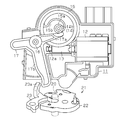
- the top view which shows the actuator which concerns on one Embodiment of this invention The top view which shows the actuator of the state which removed the worm wheel of FIG.
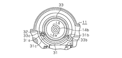
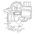
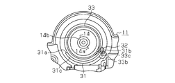
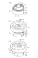
- the top view which shows the actuator of the state which removed the worm wheel of FIG. (A)-(c) is a perspective view which shows the assembly
- FIG. 1 An actuator according to an embodiment of the present invention will be described with reference to FIGS. 1 to 5 (c).
- the actuator is applied to a release device mounted on a vehicle door (not shown) such as an automobile.
- the actuator includes a box-shaped case 11 that forms the casing.
- the case 11 is made of a resin material.
- the case 11 houses an electric motor 12 on the right side of the figure.
- a rotating shaft 12 a of the electric motor 12 extends along the horizontal direction in the figure, and is rotatably supported by the case 11 at the center of the case 11.
- a worm 13 is fixed to the rotary shaft 12a.
- the case 11 is provided with a support portion 14 protruding from the bottom surface.
- the support portion 14 is disposed on the upper side of the worm 13 in the figure.
- the support portion 14 has a stepped cylindrical shape. That is, the support portion 14 has a large diameter portion located on the proximal end side and a small diameter distal end portion 14b located on the distal end side via the annular step 14a.
- the worm wheel 15 is rotatably supported by the support part 14 at the front-end
- the worm wheel 15 is rotatably supported by the support portion 14 by inserting the tip portion 14b of the support portion 14 into the shaft portion 15a of the worm wheel 15.
- the worm wheel 15 meshes with the worm 13 and rotates around the axis of the support portion 14 in conjunction with the rotation of the worm 13 (rotating shaft 12a).
- the worm wheel 15 constitutes a worm gear together with the worm 13.
- the worm wheel 15 is formed with a substantially spiral cam portion 15b that goes radially outward from the shaft portion 15a in the counterclockwise direction shown in the drawing.
- the case 11 is provided with a stopper 31 protruding from the bottom surface on the lower side in the drawing, which is the outer peripheral side of the support portion 14.
- the stopper 31 has a partial cylindrical shape concentric with the support portion 14, that is, has an arc-shaped peripheral wall.
- a first end surface 31 c is formed on the tip end side in the protruding direction of the stopper 31.
- the first end face 31 c has an arc shape centered on the center of the support portion 14, that is, the rotation axis of the worm wheel 15.
- a substantially flat cylindrical engagement protrusion 32 is provided on the bottom surface of the worm wheel 15 so as to protrude.
- the engagement protrusion 32 extends from the bottom surface of the worm wheel 15 toward the bottom surface of the case 11, that is, toward the back side orthogonal to the paper surface in FIG. 2.
- a second end face 32a (see FIG. 5B) is formed on the distal end side of the engaging protrusion 32 in the protruding direction.
- the second end surface 32a has a substantially flat circular shape.
- the stopper 31 is disposed at a position where the rotation locus of the engaging protrusion 32 is blocked when the worm wheel 15 rotates around the axis of the support portion 14.
- the rotation range of the worm wheel 15 around the axis of the support portion 14 is a predetermined rotation position (hereinafter referred to as “initial position Ps”) where the engagement protrusion 32 abuts the left end surface 31a of the stopper 31 in the drawing. Therefore, as shown in FIG. 4, a predetermined rotation position (hereinafter also referred to as “maximum rotation position Pm”) at which the engagement protrusion 32 abuts on the right end (opposite side) end surface 31b of the stopper 31 as shown in FIG. It is regulated within the range.
- a torsion coil spring 33 is accommodated in the case 11 around the axis of the support portion 14 which is the radially inner side of the stopper 31. As shown in FIGS. 5A to 5C, the torsion coil spring 33 is substantially concentric with the support portion 14 wound in the clockwise direction from the proximal end side to the distal end side of the support portion 14. Coil part 33a.
- the torsion coil spring 33 has a first leg portion 33b formed by folding back the base end of the support portion 14 connected to the coil portion 33a, and further, the tip end of the support portion 14 connected to the coil portion 33a is folded back. It has the 2nd leg part 33c.
- the tip of the coil portion 33 a is disposed more outwardly than the stopper 31 in the protruding direction of the stopper 31, that is, in the axial direction of the support portion 14. Accordingly, the second leg portion 33 c is also arranged outside the stopper 31 in the protruding direction of the stopper 31. That is, the second leg portion 33 c is disposed above the upper end 31 c of the stopper 31.
- the first leg 33b is locked to the end surface 31b of the stopper 31.
- the second leg portion 33c is disposed in the vicinity of the end face 31b in the elastic return state (free state) of the torsion coil spring 33.
- the second leg portion 33c is locked to the engaging protrusion 32 of the worm wheel 15 in a state where the second leg portion 33c is rotated in the clockwise direction in the figure against the urging force of the torsion coil spring 33 from the end surface 31b to the vicinity of the end surface 31a. Yes.
- the worm wheel 15 is biased toward the illustrated counterclockwise rotation direction, that is, the direction in which the engagement protrusion 32 is in contact with the end surface 31 a of the stopper 31, that is, the initial position Ps.
- the worm wheel 15 rotates in the clockwise direction shown in the figure against the urging force of the torsion coil spring 33, so that the maximum rotation position Pm at which the engagement protrusion 32 abuts on the end surface 31b of the stopper 31. Move to.
- the engagement protrusion 32 is a part that makes the worm wheel 15 contact the stopper 31 in order to restrict the worm wheel 15 to the initial position Ps or the maximum rotation position Pm. Further, the engaging protrusion 32 is also a part for locking the second leg portion 33 c of the torsion coil spring 33. Since the second leg 33c of the torsion coil spring 33 is locked to the engaging protrusion 32 outside the stopper 31 in the protruding direction of the stopper 31, the initial position Ps and the maximum rotation position Pm are set. In either case, the worm wheel 15 is not sandwiched between the engaging protrusion 32 and the stopper 31.
- the case 11 is provided with a stepped cylindrical support 16 protruding from the bottom surface on the left side of the rotating shaft 12a in the drawing.
- a substantially T-shaped release lever 17 is rotatably supported by the support portion 16.
- the release lever 17 has an input arm 17a that extends in the radial direction from the support portion 16 toward the worm wheel 15 and can contact the outer surface of the shaft portion 15a and the cam portion 15b.
- the release lever 17 has an output arm 17b extending from the support portion 16 in the radial direction downward in the figure. The tip end of the output arm 17b is exposed to the outside of the case 11. As shown in FIG.
- a latch mechanism 21 is installed on the vehicle door via an appropriate bracket.
- the latch mechanism 21 includes a latch 22 and a pawl 23 that are rotatably connected to a bracket around axes parallel to each other.
- the latch mechanism 21 can be engaged with and disengaged from the striker 20 fixed to the vehicle body (not shown). That is, when the vehicle door is closed, the latch 22 pressed by the striker 20 rotates and engages with the striker 20, and at the same time, the pawl 23 prevents the latch 22 from rotating, thereby holding the vehicle door in a closed state. . Further, as shown in FIG.
- the pole 23 released from the pressing force of the release lever 17 in the engagement piece 23a is urged by a pole return spring (not shown) and rotates so as to return to the position shown in FIG.
- the output arm 17b is pressed by the engagement piece 23a.
- the coil portion 33a of the torsion coil spring 33 in the elastic return state is radially inward of the stopper 31 around the axis of the support portion 14 of the case 11. It is disposed coaxially with the support portion 14 and is accommodated in the case 11.
- the first leg 33 b is locked to the end surface 31 b of the stopper 31.
- the tip of the coil portion 33 a of the torsion coil spring 33 is disposed outside the stopper 31 in the protruding direction of the stopper 31.
- the second leg portion 33 c is disposed near the end surface 31 b of the stopper 31 and on the outer side of the stopper 31 in the protruding direction of the stopper 31.
- the shaft portion 15a of the worm wheel 15 is inserted into the tip portion 14b of the case 11, and the protruding portion of the second leg portion 33c outward from the stopper 31 is engaged. Instead, the engaging protrusion 32 of the worm wheel 15 is generally locked to the second leg 33c. At this time, the second end surface 32 a of the engagement protrusion 32 abuts on the first end surface 31 c of the stopper 31.
- the worm wheel 15 is rotated around the axis of the tip end portion 14b in the clockwise direction in the figure against the urging force of the torsion coil spring 33.
- the first end surface 31 c of the stopper 31 abuts on the second end surface 32 a of the engaging protrusion 32 to guide the assembly of the worm wheel 15.
- the engaging protrusion 32 slides on the stopper 31, that is, on the first end surface 31 c.
- the worm wheel 15 rotates to a position where the engaging protrusion 32 gets over the stopper 31, that is, a position corresponding to the initial position Ps, the worm wheel 15 is moved in the axial direction toward the base end of the support portion 14. .
- the worm wheel 15 is placed on the step 14a.
- the engagement protrusion 32 abuts against the end surface 31a of the stopper 31 in the circumferential direction in such a manner that the engagement margin between the second leg portion 33c and the engagement protrusion 32 is increased. Touch.
- the worm wheel 15 is disposed at the initial position Ps with the torsion coil spring 33 interposed, and the assembly of the worm wheel 15 to the case 11 is completed.
- the striker 20 and the latch mechanism 21 are engaged with each other, the vehicle door is held in a closed state, and the worm wheel 15 released from the driving force of the electric motor 12 is moved to the initial position Ps. It shall be arranged in.
- the worm 13 is rotated by the electric motor 12 in this state, the worm wheel 15 rotates in the clockwise direction in the figure against the urging force of the torsion coil spring 33.
- the release lever 17 rotates in the clockwise direction in the figure in conjunction with the rotation of the worm wheel 15, the output arm 17b presses the engagement piece 23a of the pole 23 as shown in FIG. As a result, the pole 23 is rotated to release the latch 22 from being rotated.
- the latch 22 is urged by a latch return spring (not shown) and rotates so as to return to the release position, and the engagement state with the striker 20 is released to make the vehicle door openable.
- the rotation of the worm wheel 15 is restricted by the engagement protrusion 32 coming into contact with the end surface 31 b of the stopper 31. Therefore, the worm wheel 15 is disposed at the maximum rotation position Pm.
- the worm wheel 15 is urged by the torsion coil spring 33 and rotates so as to return in the counterclockwise direction shown in the drawing.
- the rotation of the worm wheel 15 is restricted by the engagement protrusion 32 coming into contact with the end surface 31 a of the stopper 31. Therefore, the worm wheel 15 is disposed at the initial position Ps. Accordingly, the pole 23 released from the pressing force of the release lever 17 is urged by a pole return spring (not shown) and rotates so as to return to the rotation position shown in FIG.
- the worm wheel 15 is assembled to the case 11 with a torsion coil spring 33 interposed therebetween.
- the torsion coil spring 33 is temporarily assembled to the case 11 in a state where the first leg portion 33 b of the torsion coil spring 33 is engaged with the end surface 31 b of the case 11.
- the torsion coil spring 33 is accommodated in the case 11 in an elastic return state (free state), and the second leg portion 33 c is disposed outside the stopper 31 in the protruding direction of the stopper 31.
- the second leg portion 33 c is locked to the engagement protrusion 32 by the engagement margin of the protruding portion of the second leg portion 33 c outward from the stopper 31.
- the worm wheel 15 is rotated against the biasing force of the torsion coil spring 33 to a position where the engaging protrusion 32 gets over the stopper 31, that is, a position corresponding to the initial position Ps.
- the engagement protrusion 32 is increased while increasing the engagement margin of the second leg portion 33 c and the engagement protrusion 32. It contacts the end face 31a of the stopper 31 in the circumferential direction.
- the worm wheel 15 is disposed at the initial position Ps with the torsion coil spring 33 interposed, and the assembly of the worm wheel 15 to the case 11 is completed.
- the second leg portion 33 c is disposed outside the stopper 31 in the protruding direction of the stopper 31.
- the assembly of the worm wheel 15 to the case 11 can be performed smoothly. Further, since it is not necessary to set a gap between the members in order to facilitate the assembly work of the members such as the worm wheel 15, it is possible to suppress the occurrence of rattling and abnormal noise resulting therefrom. .
- the stopper 31 is also used as a stopper for restricting the worm wheel 15 to a predetermined maximum rotation position Pm.
- the case 11 can be made a simpler shape as compared with the case where the stopper for the initial position Ps and the stopper for the maximum rotation position Pm are individually provided.
- the first end face 31 c of the stopper 31 has an arc shape centered on the rotational axis of the worm wheel 15. Therefore, if the worm wheel 15 is rotated and assembled, the second end surface 32a can be brought into contact with the first end surface 31c without fail. Therefore, the assembling property of the worm wheel 15 and the torsion coil spring 33 can be further improved.
- the stopper 31 may restrict the rotation of the worm wheel 15 only at the initial position Ps.
- a maximum rotation position stopper that restricts the worm wheel 15 to the maximum rotation position Pm may be separately provided at an appropriate position of the case 11.
- the stopper 31 that restricts the rotation of the worm wheel 15 only at the initial position Ps may be reduced in the circumferential direction.
- the second leg portion 33c is engaged with the engaging protrusion 32 by the engagement margin of the protruding portion of the second leg portion 33c outward from the stopper 31. There is no wall portion (stopper 31) that can slide the engagement protrusion 32 when stopped.
- the first leg 33b of the torsion coil spring 33 may be locked at an appropriate position of the case 11 other than the end face 31b of the stopper 31.
- the configuration of each part in the above embodiment may be appropriately changed.
- the coil portion 33a of the torsion coil spring 33 may be compressed in the axial direction after the worm wheel 15 is assembled.
- Each of the first end surface 31c of the stopper 31 and the second end surface 32a of the engaging protrusion 32 is not limited to a so-called tip surface in the protruding direction.
- a step surface may be formed at the tip of the stopper 31 or the engaging protrusion 32.
- the output member is not limited to the worm wheel 15 constituting the worm gear, and may be an appropriate gear or lever driven by the electric motor 12.
- the present invention may be applied to a closer device that drives the latch mechanism 21 to hold the vehicle door in a closed state.
- the present invention may be applied to an appropriate device that performs a required operation by rotating the output member against the biasing force of the torsion coil spring by the driving force of the electric motor.
Landscapes
- Lock And Its Accessories (AREA)
Priority Applications (1)
| Application Number | Priority Date | Filing Date | Title |
|---|---|---|---|
| CN201290000227.0U CN203499391U (zh) | 2011-04-08 | 2012-04-04 | 致动器 |
Applications Claiming Priority (2)
| Application Number | Priority Date | Filing Date | Title |
|---|---|---|---|
| JP2011-086474 | 2011-04-08 | ||
| JP2011086474A JP5327266B2 (ja) | 2011-04-08 | 2011-04-08 | アクチュエータ |
Publications (1)
| Publication Number | Publication Date |
|---|---|
| WO2012137808A1 true WO2012137808A1 (ja) | 2012-10-11 |
Family
ID=46969202
Family Applications (1)
| Application Number | Title | Priority Date | Filing Date |
|---|---|---|---|
| PCT/JP2012/059164 Ceased WO2012137808A1 (ja) | 2011-04-08 | 2012-04-04 | アクチュエータ |
Country Status (3)
| Country | Link |
|---|---|
| JP (1) | JP5327266B2 (enExample) |
| CN (1) | CN203499391U (enExample) |
| WO (1) | WO2012137808A1 (enExample) |
Cited By (2)
| Publication number | Priority date | Publication date | Assignee | Title |
|---|---|---|---|---|
| WO2019076409A1 (de) * | 2017-10-20 | 2019-04-25 | Kiekert Ag | Kraftfahrzeugschliesssystem mit elektrischer öffnungseinrichtung |
| IT201800010174A1 (it) * | 2018-11-08 | 2020-05-08 | Cebi Italy Spa | Serratura per veicolo con sistema di riarmo perfezionato. |
Families Citing this family (6)
| Publication number | Priority date | Publication date | Assignee | Title |
|---|---|---|---|---|
| JP6232809B2 (ja) * | 2013-07-31 | 2017-11-22 | アイシン精機株式会社 | アクチュエータ装置 |
| JP6379401B2 (ja) * | 2014-09-11 | 2018-08-29 | 北川工業株式会社 | 出力ノイズ低減装置 |
| JP6507407B2 (ja) * | 2015-01-08 | 2019-05-08 | 三井金属アクト株式会社 | 車両トランクリッド用ラッチ装置 |
| EP3511496B1 (fr) * | 2018-01-10 | 2020-07-08 | U-Shin France | Serrure a trois positions pour vehicule automobile |
| DE102018109477A1 (de) * | 2018-04-20 | 2019-10-24 | Kiekert Ag | Kraftfahrzeug-Antriebsanordnung |
| CN108661464B (zh) * | 2018-07-13 | 2023-11-28 | 无锡忻润汽车安全系统有限公司 | 带自动回位功能的汽车门锁电开机构 |
Citations (1)
| Publication number | Priority date | Publication date | Assignee | Title |
|---|---|---|---|---|
| JP2004244931A (ja) * | 2003-02-14 | 2004-09-02 | Shiroki Corp | ロック装置 |
-
2011
- 2011-04-08 JP JP2011086474A patent/JP5327266B2/ja not_active Expired - Fee Related
-
2012
- 2012-04-04 CN CN201290000227.0U patent/CN203499391U/zh not_active Expired - Fee Related
- 2012-04-04 WO PCT/JP2012/059164 patent/WO2012137808A1/ja not_active Ceased
Patent Citations (1)
| Publication number | Priority date | Publication date | Assignee | Title |
|---|---|---|---|---|
| JP2004244931A (ja) * | 2003-02-14 | 2004-09-02 | Shiroki Corp | ロック装置 |
Cited By (3)
| Publication number | Priority date | Publication date | Assignee | Title |
|---|---|---|---|---|
| WO2019076409A1 (de) * | 2017-10-20 | 2019-04-25 | Kiekert Ag | Kraftfahrzeugschliesssystem mit elektrischer öffnungseinrichtung |
| US11525288B2 (en) | 2017-10-20 | 2022-12-13 | Kiekert Ag | Motor vehicle locking system with an electrical opening device |
| IT201800010174A1 (it) * | 2018-11-08 | 2020-05-08 | Cebi Italy Spa | Serratura per veicolo con sistema di riarmo perfezionato. |
Also Published As
| Publication number | Publication date |
|---|---|
| CN203499391U (zh) | 2014-03-26 |
| JP5327266B2 (ja) | 2013-10-30 |
| JP2012219510A (ja) | 2012-11-12 |
Similar Documents
| Publication | Publication Date | Title |
|---|---|---|
| WO2012137808A1 (ja) | アクチュエータ | |
| JP4760887B2 (ja) | ドアロック装置 | |
| WO2015098548A1 (ja) | パワーステアリング装置 | |
| WO2012117958A1 (ja) | 車両用ロック装置 | |
| JPWO2016185973A1 (ja) | 開閉体の電動式ロック装置 | |
| JP5260358B2 (ja) | 電動ステアリングロック装置 | |
| JP2016070021A (ja) | ロック解除装置およびそれを備えるロック装置 | |
| JP5260360B2 (ja) | 電動ステアリングロック装置 | |
| JP7436746B2 (ja) | 開閉体の電動式ロック装置 | |
| US11299917B2 (en) | Vehicle door latch device | |
| JP5260359B2 (ja) | 電動ステアリングロック装置 | |
| JP2016216927A (ja) | ロック装置 | |
| CN107075883B (zh) | 门锁装置的装配方法和门锁装置 | |
| JP2008192417A (ja) | ターンシグナルスイッチ装置 | |
| JP2009171686A (ja) | モータ及びその製造方法 | |
| KR20210117400A (ko) | 스텝 엑츄에이터 및 전자 기기 | |
| JP5805979B2 (ja) | 錠装置 | |
| KR101384770B1 (ko) | 차량용 어시스트 핸들 | |
| WO2013146653A1 (ja) | 車両用ドアハンドル装置 | |
| JP7206877B2 (ja) | 車両用ドアロック構造 | |
| JP6520350B2 (ja) | クラッチ装置及びアクチュエータ | |
| JP4837418B2 (ja) | アクチュエータ装置 | |
| JP2025089897A (ja) | 自動車用ドアラッチ装置 | |
| JP2013237373A (ja) | 車両用ドアミラー | |
| JP2012255529A (ja) | パークロック構造 |
Legal Events
| Date | Code | Title | Description |
|---|---|---|---|
| WWE | Wipo information: entry into national phase |
Ref document number: 201290000227.0 Country of ref document: CN |
|
| 121 | Ep: the epo has been informed by wipo that ep was designated in this application |
Ref document number: 12768592 Country of ref document: EP Kind code of ref document: A1 |
|
| NENP | Non-entry into the national phase |
Ref country code: DE |
|
| WWE | Wipo information: entry into national phase |
Ref document number: 1301003824 Country of ref document: TH |
|
| 122 | Ep: pct application non-entry in european phase |
Ref document number: 12768592 Country of ref document: EP Kind code of ref document: A1 |