WO2012137573A1 - 燃焼バーナ、固体燃料焚きバーナ並びに固体燃料焚きボイラ、ボイラ及びボイラの運転方法 - Google Patents
燃焼バーナ、固体燃料焚きバーナ並びに固体燃料焚きボイラ、ボイラ及びボイラの運転方法 Download PDFInfo
- Publication number
- WO2012137573A1 WO2012137573A1 PCT/JP2012/055850 JP2012055850W WO2012137573A1 WO 2012137573 A1 WO2012137573 A1 WO 2012137573A1 JP 2012055850 W JP2012055850 W JP 2012055850W WO 2012137573 A1 WO2012137573 A1 WO 2012137573A1
- Authority
- WO
- WIPO (PCT)
- Prior art keywords
- fuel
- air
- flame
- burner
- nozzle
- Prior art date
Links
- 238000002485 combustion reaction Methods 0.000 title claims abstract description 457
- 238000000034 method Methods 0.000 title claims description 11
- 239000000446 fuel Substances 0.000 claims abstract description 415
- 239000002737 fuel gas Substances 0.000 claims abstract description 312
- 239000004449 solid propellant Substances 0.000 claims abstract description 154
- 239000003381 stabilizer Substances 0.000 claims abstract description 20
- 239000007787 solid Substances 0.000 claims description 64
- 230000002093 peripheral effect Effects 0.000 claims description 59
- 238000009826 distribution Methods 0.000 claims description 31
- 238000007664 blowing Methods 0.000 claims description 25
- 238000011144 upstream manufacturing Methods 0.000 claims description 17
- 230000001603 reducing effect Effects 0.000 claims description 12
- 239000000843 powder Substances 0.000 claims description 11
- 238000011017 operating method Methods 0.000 claims description 3
- 239000003245 coal Substances 0.000 abstract description 298
- 239000000203 mixture Substances 0.000 abstract description 35
- 229910052760 oxygen Inorganic materials 0.000 description 55
- 239000001301 oxygen Substances 0.000 description 55
- QVGXLLKOCUKJST-UHFFFAOYSA-N atomic oxygen Chemical compound [O] QVGXLLKOCUKJST-UHFFFAOYSA-N 0.000 description 53
- 239000007789 gas Substances 0.000 description 45
- 238000002156 mixing Methods 0.000 description 32
- 230000004048 modification Effects 0.000 description 23
- 238000012986 modification Methods 0.000 description 23
- 230000009467 reduction Effects 0.000 description 17
- 238000010586 diagram Methods 0.000 description 15
- 230000007246 mechanism Effects 0.000 description 15
- 238000009841 combustion method Methods 0.000 description 14
- XLYOFNOQVPJJNP-UHFFFAOYSA-N water Substances O XLYOFNOQVPJJNP-UHFFFAOYSA-N 0.000 description 14
- 239000000567 combustion gas Substances 0.000 description 13
- 230000008859 change Effects 0.000 description 9
- 238000009792 diffusion process Methods 0.000 description 9
- 230000007423 decrease Effects 0.000 description 7
- 238000010298 pulverizing process Methods 0.000 description 6
- 230000001105 regulatory effect Effects 0.000 description 6
- 229920006395 saturated elastomer Polymers 0.000 description 6
- 238000000926 separation method Methods 0.000 description 6
- 230000003111 delayed effect Effects 0.000 description 5
- 238000013459 approach Methods 0.000 description 4
- 238000005520 cutting process Methods 0.000 description 4
- 239000000463 material Substances 0.000 description 4
- 230000032258 transport Effects 0.000 description 4
- NINIDFKCEFEMDL-UHFFFAOYSA-N Sulfur Chemical compound [S] NINIDFKCEFEMDL-UHFFFAOYSA-N 0.000 description 3
- 238000009825 accumulation Methods 0.000 description 3
- 239000003054 catalyst Substances 0.000 description 3
- 230000001276 controlling effect Effects 0.000 description 3
- 238000006477 desulfuration reaction Methods 0.000 description 3
- 230000023556 desulfurization Effects 0.000 description 3
- 239000000428 dust Substances 0.000 description 3
- 230000000694 effects Effects 0.000 description 3
- 239000012717 electrostatic precipitator Substances 0.000 description 3
- 230000006698 induction Effects 0.000 description 3
- 238000002347 injection Methods 0.000 description 3
- 239000007924 injection Substances 0.000 description 3
- 230000001590 oxidative effect Effects 0.000 description 3
- 239000013618 particulate matter Substances 0.000 description 3
- 230000008569 process Effects 0.000 description 3
- 239000000126 substance Substances 0.000 description 3
- 229910052717 sulfur Inorganic materials 0.000 description 3
- 239000011593 sulfur Substances 0.000 description 3
- 238000012546 transfer Methods 0.000 description 3
- 206010021143 Hypoxia Diseases 0.000 description 2
- 230000002411 adverse Effects 0.000 description 2
- 230000015572 biosynthetic process Effects 0.000 description 2
- 230000003247 decreasing effect Effects 0.000 description 2
- 230000002950 deficient Effects 0.000 description 2
- 238000000227 grinding Methods 0.000 description 2
- 229930195733 hydrocarbon Natural products 0.000 description 2
- 150000002430 hydrocarbons Chemical class 0.000 description 2
- 238000004519 manufacturing process Methods 0.000 description 2
- 230000003647 oxidation Effects 0.000 description 2
- 238000007254 oxidation reaction Methods 0.000 description 2
- 230000001737 promoting effect Effects 0.000 description 2
- 238000005728 strengthening Methods 0.000 description 2
- RNFJDJUURJAICM-UHFFFAOYSA-N 2,2,4,4,6,6-hexaphenoxy-1,3,5-triaza-2$l^{5},4$l^{5},6$l^{5}-triphosphacyclohexa-1,3,5-triene Chemical compound N=1P(OC=2C=CC=CC=2)(OC=2C=CC=CC=2)=NP(OC=2C=CC=CC=2)(OC=2C=CC=CC=2)=NP=1(OC=1C=CC=CC=1)OC1=CC=CC=C1 RNFJDJUURJAICM-UHFFFAOYSA-N 0.000 description 1
- 230000001154 acute effect Effects 0.000 description 1
- 230000008901 benefit Effects 0.000 description 1
- 239000012141 concentrate Substances 0.000 description 1
- 230000008021 deposition Effects 0.000 description 1
- 238000001514 detection method Methods 0.000 description 1
- 238000002474 experimental method Methods 0.000 description 1
- 239000003063 flame retardant Substances 0.000 description 1
- 238000010248 power generation Methods 0.000 description 1
- 230000002265 prevention Effects 0.000 description 1
- 230000003014 reinforcing effect Effects 0.000 description 1
- 230000002441 reversible effect Effects 0.000 description 1
Images


Classifications
-
- F—MECHANICAL ENGINEERING; LIGHTING; HEATING; WEAPONS; BLASTING
- F23—COMBUSTION APPARATUS; COMBUSTION PROCESSES
- F23D—BURNERS
- F23D1/00—Burners for combustion of pulverulent fuel
- F23D1/005—Burners for combustion of pulverulent fuel burning a mixture of pulverulent fuel delivered as a slurry, i.e. comprising a carrying liquid
-
- F—MECHANICAL ENGINEERING; LIGHTING; HEATING; WEAPONS; BLASTING
- F23—COMBUSTION APPARATUS; COMBUSTION PROCESSES
- F23C—METHODS OR APPARATUS FOR COMBUSTION USING FLUID FUEL OR SOLID FUEL SUSPENDED IN A CARRIER GAS OR AIR
- F23C5/00—Disposition of burners with respect to the combustion chamber or to one another; Mounting of burners in combustion apparatus
- F23C5/08—Disposition of burners
- F23C5/32—Disposition of burners to obtain rotating flames, i.e. flames moving helically or spirally
-
- F—MECHANICAL ENGINEERING; LIGHTING; HEATING; WEAPONS; BLASTING
- F23—COMBUSTION APPARATUS; COMBUSTION PROCESSES
- F23C—METHODS OR APPARATUS FOR COMBUSTION USING FLUID FUEL OR SOLID FUEL SUSPENDED IN A CARRIER GAS OR AIR
- F23C6/00—Combustion apparatus characterised by the combination of two or more combustion chambers or combustion zones, e.g. for staged combustion
- F23C6/04—Combustion apparatus characterised by the combination of two or more combustion chambers or combustion zones, e.g. for staged combustion in series connection
- F23C6/045—Combustion apparatus characterised by the combination of two or more combustion chambers or combustion zones, e.g. for staged combustion in series connection with staged combustion in a single enclosure
-
- F—MECHANICAL ENGINEERING; LIGHTING; HEATING; WEAPONS; BLASTING
- F23—COMBUSTION APPARATUS; COMBUSTION PROCESSES
- F23D—BURNERS
- F23D1/00—Burners for combustion of pulverulent fuel
-
- F—MECHANICAL ENGINEERING; LIGHTING; HEATING; WEAPONS; BLASTING
- F23—COMBUSTION APPARATUS; COMBUSTION PROCESSES
- F23L—SUPPLYING AIR OR NON-COMBUSTIBLE LIQUIDS OR GASES TO COMBUSTION APPARATUS IN GENERAL ; VALVES OR DAMPERS SPECIALLY ADAPTED FOR CONTROLLING AIR SUPPLY OR DRAUGHT IN COMBUSTION APPARATUS; INDUCING DRAUGHT IN COMBUSTION APPARATUS; TOPS FOR CHIMNEYS OR VENTILATING SHAFTS; TERMINALS FOR FLUES
- F23L9/00—Passages or apertures for delivering secondary air for completing combustion of fuel
- F23L9/02—Passages or apertures for delivering secondary air for completing combustion of fuel by discharging the air above the fire
-
- F—MECHANICAL ENGINEERING; LIGHTING; HEATING; WEAPONS; BLASTING
- F23—COMBUSTION APPARATUS; COMBUSTION PROCESSES
- F23N—REGULATING OR CONTROLLING COMBUSTION
- F23N3/00—Regulating air supply or draught
-
- F—MECHANICAL ENGINEERING; LIGHTING; HEATING; WEAPONS; BLASTING
- F23—COMBUSTION APPARATUS; COMBUSTION PROCESSES
- F23C—METHODS OR APPARATUS FOR COMBUSTION USING FLUID FUEL OR SOLID FUEL SUSPENDED IN A CARRIER GAS OR AIR
- F23C2201/00—Staged combustion
- F23C2201/20—Burner staging
-
- F—MECHANICAL ENGINEERING; LIGHTING; HEATING; WEAPONS; BLASTING
- F23—COMBUSTION APPARATUS; COMBUSTION PROCESSES
- F23D—BURNERS
- F23D2201/00—Burners adapted for particulate solid or pulverulent fuels
- F23D2201/10—Nozzle tips
-
- F—MECHANICAL ENGINEERING; LIGHTING; HEATING; WEAPONS; BLASTING
- F23—COMBUSTION APPARATUS; COMBUSTION PROCESSES
- F23D—BURNERS
- F23D2201/00—Burners adapted for particulate solid or pulverulent fuels
- F23D2201/10—Nozzle tips
- F23D2201/101—Nozzle tips tiltable
-
- F—MECHANICAL ENGINEERING; LIGHTING; HEATING; WEAPONS; BLASTING
- F23—COMBUSTION APPARATUS; COMBUSTION PROCESSES
- F23D—BURNERS
- F23D2201/00—Burners adapted for particulate solid or pulverulent fuels
- F23D2201/20—Fuel flow guiding devices
-
- F—MECHANICAL ENGINEERING; LIGHTING; HEATING; WEAPONS; BLASTING
- F23—COMBUSTION APPARATUS; COMBUSTION PROCESSES
- F23D—BURNERS
- F23D2209/00—Safety arrangements
- F23D2209/20—Flame lift-off / stability
-
- F—MECHANICAL ENGINEERING; LIGHTING; HEATING; WEAPONS; BLASTING
- F23—COMBUSTION APPARATUS; COMBUSTION PROCESSES
- F23K—FEEDING FUEL TO COMBUSTION APPARATUS
- F23K2203/00—Feeding arrangements
- F23K2203/20—Feeding/conveying devices
- F23K2203/201—Feeding/conveying devices using pneumatic means
-
- F—MECHANICAL ENGINEERING; LIGHTING; HEATING; WEAPONS; BLASTING
- F23—COMBUSTION APPARATUS; COMBUSTION PROCESSES
- F23N—REGULATING OR CONTROLLING COMBUSTION
- F23N2221/00—Pretreatment or prehandling
- F23N2221/10—Analysing fuel properties, e.g. density, calorific
Definitions
- the present invention relates to a combustion burner applied to a boiler for generating steam for power generation or factory use, for example, a solid fuel burning burner for burning a solid fuel (powder fuel) such as pulverized coal, and a solid fuel burning
- a combustion burner applied to a boiler for generating steam for power generation or factory use
- a solid fuel burning burner for burning a solid fuel (powder fuel) such as pulverized coal
- a solid fuel burning such as pulverized coal
- the present invention relates to a boiler, a boiler that generates steam by burning solid fuel and air, and a method for operating the boiler.
- a conventional pulverized coal fired boiler has a furnace having a hollow shape and installed in the vertical direction, and a plurality of combustion burners are disposed on the furnace wall along the circumferential direction, and a plurality of combustion burners are provided in the vertical direction. It is arranged over the steps.
- the combustion burner is supplied with an air-fuel mixture of pulverized coal (fuel) obtained by pulverizing coal and primary air, and also supplied with high-temperature secondary air, and blows the air-fuel mixture and secondary air into the furnace. This forms a flame and can be burned in this furnace.
- This furnace has a flue connected to the top, and this flue is provided with a superheater, reheater, economizer, etc. for recovering the heat of exhaust gas, and it was generated by combustion in the furnace. Heat exchange is performed between the exhaust gas and water, and steam can be generated.
- the combustion burner of the present invention includes a fuel nozzle capable of injecting a fuel gas mixed with solid fuel and air, a secondary air nozzle capable of injecting air from the outside of the fuel nozzle, and a shaft at the tip of the fuel nozzle.
- the flow of the fuel gas flowing through the fuel nozzle is rectified by the rectifying member, and at the rear end of the flame holder.
- the flow separation is suppressed, and the flow rate is substantially constant, so that the solid fuel is prevented from being deposited on the wall surface of the fuel nozzle, and an appropriate flow of the fuel gas can be realized.
- the rectifying member is disposed with a predetermined gap from the flame holder.
- a predetermined gap is secured between the rectifying member and the flame holder, so that the fuel gas flowing between the rectifying member and the flame holder is rectified and the flame holding function by the flame holder. Can be fully exhibited.
- the rectifying member is provided so that the distance from the flame holder is substantially the same along the flow direction of the fuel gas.
- the flow rate of the fuel gas flowing between the rectifying member and the flame holder is substantially constant because the distance between the rectifying member and the flame holder is substantially the same along the flow direction of the fuel gas. Accumulation of solid fuel on the fuel nozzle and adhesion of solid fuel to the flame holder can be suppressed. Moreover, since the flow path does not become extremely narrow, blockage can be prevented.
- the flame stabilizer is provided with a widened portion on the downstream side in the fuel gas flow direction, while the rectifying member is provided with a tapered portion on the downstream side in the fuel gas flow direction. It is a feature.
- the flame stabilizer is provided with a widened portion on the downstream side in the fuel gas flow direction, while the rectifying member is provided at a position not facing the widened portion.
- the rectifying member at a position that does not face the widened portion of the flame holder, the flow path of the fuel gas between the wide portion of the flame holder and the fuel nozzle is not narrowed, and the flow rate of the fuel gas is reduced. It is possible to suppress the deposition of the solid fuel on the fuel nozzle and the adhesion of the solid fuel to the flame holder.
- the rectifying member is provided along the inner wall surface of the fuel nozzle.
- the rectifying member on the inner wall surface of the fuel nozzle, a separate mounting member is not required, the assembling property can be improved, and the manufacturing cost can be reduced.
- the flame holder is arranged so that the first flame holding member arranged along the horizontal direction intersects with the second flame holding member arranged along the vertical direction. It is characterized by a structure.
- each of the first flame holding member and the second flame holding member includes a plurality of flame holding members, and the first flame holding members are arranged with a plurality of predetermined gaps in the vertical direction.
- the plurality of second flame holding members are arranged with a predetermined gap in the horizontal direction, and the plurality of first flame holding members and the plurality of second flame holding members are arranged to intersect each other. It is said.
- the combustion burner of the present invention is characterized in that the width of one of the first flame holding member and the second flame holding member is set larger than the width of the other.
- the flame holding function in the horizontal direction can be improved by the wide first flame holding member.
- the second flame holding member does not adversely affect the second flame holding member when the direction of the nozzle is swung up and down for steam temperature control or the like. It becomes possible to improve the flame function. This is because when the nozzle moves up and down, the position of the flame holding member with respect to the position where the solid fuel is blown changes greatly when the first flame holding member is used, but hardly changes when the second flame holding member is used. .
- the combustion burner of the present invention includes a fuel nozzle capable of injecting a fuel gas mixed with solid fuel and air, a secondary air nozzle capable of injecting air from the outside of the fuel nozzle, and a tip portion of the fuel nozzle. And a guide member that guides the fuel gas flowing in the fuel nozzle to the shaft center side.
- the guide member that guides the fuel gas flowing in the fuel nozzle to the axial center side, the fuel gas flowing in the fuel nozzle is guided to the axial center side of the fuel nozzle by this guide member.
- the internal flame holding performance can be improved, and the amount of NOx generated can be reduced.
- the combustion burner of the present invention is characterized in that the guide member guides the fuel gas in a direction away from the secondary air blown by the secondary air nozzle.
- the guide member guides the fuel gas in a direction away from the secondary air, the mixing of the fuel gas and the secondary air is suppressed, and the outer periphery of the combustion flame is maintained at a low temperature.
- the amount of NOx generated by mixing the gas and the secondary air can be reduced.
- the guide member is arranged along the inner wall surface of the fuel nozzle.
- the guide member along the inner wall surface of the fuel nozzle, the fuel gas flowing through the fuel nozzle is effectively guided to the axial center side, thereby guiding the fuel gas in the direction away from the secondary air. be able to.
- the combustion burner according to the present invention is characterized in that the guide member is disposed at the tip of the fuel nozzle so as to face the flame holder.
- the internal flame holding performance can be improved by arranging the guide member so as to face the flame holder.
- the combustion burner according to the present invention is characterized in that the guide member is disposed at a position facing the inner wall surface of the fuel nozzle in the flame holder.
- the fuel gas flowing along the flame holder can be effectively collected and held at the tip of the flame holder by the guide member.
- the combustion burner according to the present invention is characterized in that the guide member is arranged upstream of the flame holder in the fuel gas flow direction.
- the guide member and the flame holder are separated from each other, the guide member does not impair the flame holding function of the flame holder.
- the flame holder is parallel to the two first flame holding members that are parallel with a predetermined gap in the vertical direction along the horizontal direction and with a predetermined gap in the horizontal direction along the vertical direction.
- the two second flame holding members are arranged so as to intersect with each other, and the guide member is arranged outside the position where the first flame holding member and the second flame holding member intersect. It is characterized by.
- the flame holder a double cross structure, it becomes possible to ensure a sufficient flame holding function, and the fuel gas flowing in the fuel nozzle can be effectively guided to the axial center side by the guide member.
- the flame holder has a widened portion on the downstream side in the flow direction of the fuel gas, and the guide member is arranged to face the widened portion.
- the combustion burner of the present invention has two flame holding members that are parallel to each other with a predetermined gap in the vertical direction along the horizontal direction, and the tip portion of the flame holding member faces the axial center side of the fuel nozzle. It is characterized by constituting a guide member.
- the structure can be simplified by configuring the guide member with the flame holding member.
- the solid fuel burning burner of the present invention is used in the burner portion of a solid fuel burning boiler that performs low NOx combustion separately into a burner portion and an additional air charging portion, and the powdered solid fuel and air are fed into the furnace.
- a solid fuel-burning burner is provided with a fuel burner for charging powdered fuel and primary air into the furnace, and a secondary air charging port for injecting secondary air from the outer periphery of the fuel burner.
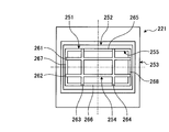
- a cross-type split member in which members in a plurality of directions are crossed as an internal flame holding member is disposed in the road front portion, and the width dimension of the split member is different for each direction.
- the solid fuel burning burner has a fuel burner that inputs powdered fuel and primary air into the furnace, and a secondary air input port that injects secondary air from the outer periphery of the fuel burner.
- a cross-type split member in which members in a plurality of directions are crossed as internal flame holding at the front part of the flow path of the fuel burner, and the width dimension of the split member varies depending on the direction, so the outlet opening
- the split member installed near the center divides the flow path of pulverized coal and air, disturbs the flow inside, and forms a recirculation zone in front of the split member, thus functioning as an internal flame holding mechanism. As a result, it is possible to suppress the high temperature oxygen remaining region formed on the outer periphery of the flame.
- the cross-type split member is preferably wide in the vertical direction, so that the positional relationship with the splitter member hardly changes even when the nozzle angle is changed in the vertical direction.
- the cross-type split member is preferably wide in the left-right direction. This enhances the lateral splitter function, so that direct interference with the secondary air introduced from above and below is prevented. Can be suppressed.
- cross-type split members are disposed in at least one of the left-right direction and the up-down direction, and at least one central part in the left-right direction and the up-down direction is wide.
- the solid fuel burning burner of the present invention is used in the burner portion of a solid fuel burning boiler that performs low NOx combustion separately in a burner portion and an additional air charging portion, and a fuel burner having an internal flame holding, and a flame holding
- a solid-fuel-burning burner for supplying a solid fuel and air in powder form into the furnace, wherein the solid-fuel burning burner inputs the powder fuel and primary air into the furnace
- the shielding member which reduces a flow-path cross-sectional area is provided in at least 1 place of the crossing angle part formed by the said split member crossing, It is characterized by the above-mentioned.
- the solid fuel-fired burner has a fuel burner that inputs powdered fuel and primary air into the furnace, and a secondary air input port that injects secondary air from the outer periphery of the fuel burner.
- a cross-type split member in which members in a plurality of directions are crossed at the front part of the flow path of the fuel burner, and the flow path is cut off at least at one of the intersecting corners formed by the crossing of the split members. Since the shielding member for reducing the area is provided, the internal flame holding function by the cross-type split member can be further enhanced.
- the solid fuel-fired boiler preferably performs low-NOx combustion separately in a burner part and an additional air input part, so that the reduction can be further enhanced by dividing the additional input air.
- the solid fuel-fired boiler according to the present invention is characterized in that a solid fuel-fired burner for charging pulverized fuel and air into the furnace is disposed at a corner portion or a wall surface portion in the furnace.
- the center of the outlet opening of the fuel burner A split member arranged in the vicinity and functioning as an internal flame holding mechanism divides the flow path of the pulverized fuel and air to disturb the flow.
- air mixing and diffusion are promoted to the inside of the flame, and the ignition surface is further subdivided, so that the ignition position approaches the center of the flame and the unburned portion of the fuel is reduced. That is, oxygen easily enters the center of the flame, so that internal ignition is effectively performed, and therefore, rapid reduction is performed inside the flame and the amount of NOx generated is reduced.
- the solid fuel-fired burner of the present invention is used in the burner portion of a solid fuel-fired boiler that performs low-NOx combustion separately in a burner portion and an additional air input portion, and inputs solid powder fuel and air into the furnace.
- a solid fuel-burning burner includes a fuel burner that inputs pulverized fuel and primary air into the furnace, and a call secondary port that injects secondary air from the outer periphery of the fuel burner, and a forward portion of the flow path of the fuel burner
- a split member is disposed as an internal flame-holding member, and a part of the end adjacent to the secondary call port is removed on the outer peripheral side of the split member.
- the solid fuel burning burner includes a fuel burner that inputs pulverized fuel and primary air into the furnace, and a call secondary port that injects secondary air from the outer periphery of the fuel burner.
- a split member is disposed as an internal flame holding member at the front portion of the flow path of the fuel burner, and a part of the end adjacent to the secondary call port is removed on the outer peripheral side of the split member.
- the split member installed near the center of the outlet opening divides the flow path of pulverized coal and air to disturb the flow inside. Furthermore, since this split member forms a recirculation zone in front of the split member, it functions as an internal flame holding mechanism. As a result, it is possible to suppress the high temperature oxygen remaining region formed on the outer periphery of the flame.
- the internal flame holding member is preferably a cross-type split member in which members in a plurality of directions are crossed.
- the cross-type split member preferably has at least one end portion of a plurality of directions removed, whereby the ignition source at the end portion of the split member is reduced and internal ignition is performed. Can be promoted. That is, it is sufficient that at least one of the upper and lower and left and right end portions of the cross-type split member that intersects the upper and lower and left and right directions is removed.
- three or more cross-type split members are disposed in at least one of the vertical and horizontal directions, and at least one of the cross-type split members disposed in the central part of the vertical and horizontal directions is removed. It is preferable that the split member does not exist in a region that is considered to contribute most to the peripheral ignition.
- the solid fuel-fired boiler preferably performs low-NOx combustion separately in a burner part and an additional air input part, so that the reduction can be further enhanced by dividing the additional input air.
- the solid fuel-fired boiler according to the present invention is characterized in that a solid fuel-fired burner for charging pulverized fuel and air into the furnace is disposed at a corner portion or a wall surface portion in the furnace.
- the center of the outlet opening of the fuel burner A split member arranged in the vicinity and functioning as an internal flame holding mechanism divides the flow path of the pulverized fuel and air to disturb the flow.
- air mixing and diffusion are promoted to the inside of the flame, and the ignition surface is further subdivided, so that the ignition position approaches the center of the flame and the unburned portion of the fuel is reduced. That is, oxygen easily enters the center of the flame, so that internal ignition is effectively performed, and therefore, rapid reduction is performed inside the flame and the amount of NOx generated is reduced.
- the split member can suppress ignition that becomes an ignition source, and the flame holding function can be effectively used on the center side of the split member that is inside the flame. .
- a boiler according to the present invention includes a furnace that burns solid fuel and air, a heat exchanger that performs heat exchange in the furnace and recovers heat, and a fuel gas that is a mixture of solid fuel and primary air in the furnace.
- the control device controls the air amount adjusting device in accordance with the volatile content of the solid fuel, and this air amount adjusting device adjusts the air amount supplied to the fuel nozzle, the secondary air nozzle, and the additional air nozzle.
- the amount of primary air, the amount of secondary air, and the amount of additional air are adjusted according to the volatile content of the solid fuel, so that the volatile content of the solid fuel can be combusted properly and the solid fuel is combusted properly. Therefore, it is possible to improve the boiler operation efficiency by suppressing the generation of NOx and unburned components.
- control device controls the air amount adjusting device according to the volatile content of the solid fuel, and distributes the total air amount of the primary air and the secondary air and the air amount of the additional air. It is characterized by adjusting.
- the total air amount of the primary air and the secondary air is the amount of air necessary for burning the volatile matter of the solid fuel, and the sum of the primary air and the secondary air according to the volatile matter of the solid fuel. By changing the amount of air, the volatile matter of the solid fuel can be combusted properly.
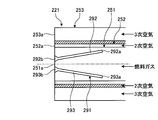
- the furnace is provided with a tertiary air nozzle capable of blowing tertiary air from the outside of the secondary air nozzle, and the control device sets the air amount adjusting device according to the volatile matter of the solid fuel. And controlling the distribution of the total air amount of the primary air and the secondary air and the total air amount of the tertiary air and the additional air.
- the volatile matter of the solid fuel can be combusted appropriately by changing the total air amount of the primary air and the secondary air.
- control device controls the air amount adjusting device so that the primary air amount and the additional air amount are set to predetermined air amounts, and the secondary air according to the volatile content of the solid fuel. And the distribution of the tertiary air.
- the primary air is a carrier air for transporting the solid fuel
- the additional air completes the combustion of the solid fuel and suppresses the generation of NOx.
- the boiler according to the present invention is characterized in that the control device increases the distribution of the secondary air when the volatile content of the solid fuel increases.
- the secondary air is combustion air for mixing the fuel gas and burning the solid fuel, if the volatile matter content of the solid fuel increases, the distribution of the secondary air increases, The volatile matter can be combusted properly.
- the boiler operating method of the present invention includes a furnace for burning solid fuel and air, a heat exchanger for performing heat exchange in the furnace to recover heat, and solid fuel and primary air in the furnace.
- a fuel nozzle capable of injecting mixed fuel gas, a secondary air nozzle capable of injecting secondary air into the furnace from outside the fuel nozzle, and the fuel nozzle and the secondary air nozzle in the furnace are added above the fuel nozzle.
- the distribution of secondary air and tertiary air is adjusted according to the volatile content of the solid fuel.
- the volatile content of the solid fuel can be combusted properly and the solid fuel can be combusted properly. It is possible to improve the boiler operating efficiency by suppressing the generation of NOx and unburned fuel.
- the boiler operation method of the present invention is characterized in that the distribution of secondary air is increased when the volatile content of the solid fuel increases.
- the secondary air is combustion air for mixing the fuel gas and burning the solid fuel, if the volatile matter content of the solid fuel increases, the distribution of the secondary air increases, The volatile matter can be combusted properly.
- a fuel nozzle capable of injecting fuel gas mixed with solid fuel and air
- a secondary air nozzle capable of injecting air from the outside of the fuel nozzle
- a shaft at the tip of the fuel nozzle Since the flame holder provided on the core side and the rectifying member provided between the inner wall surface of the fuel nozzle and the flame holder are provided, an appropriate flow of the fuel gas can be realized.
- a fuel nozzle capable of injecting a fuel gas in which solid fuel and air are mixed
- a secondary air nozzle capable of injecting air from the outside of the fuel nozzle
- a tip portion of the fuel nozzle Since a flame holder provided on the shaft center side and a guide member that guides the fuel gas flowing in the fuel nozzle to the shaft center side are provided, an appropriate flow of the fuel gas can be realized. Flame performance can be improved.
- the multi-directional split member functioning as an internal flame holding mechanism is provided at the outlet opening of the fuel burner, the outlet of the fuel burner at which the split members intersect In the vicinity of the center of the opening, the flow path of the pulverized fuel and air can be divided to disturb the flow, and the split member subdivides the ignition surface. Therefore, the ignition position is closer to the center of the flame, and since the oxygen concentration is relatively low in the center, rapid reduction is performed inside the flame, and the amount of NOx finally emitted from the solid fuel-fired boiler Is reduced. Furthermore, by providing the splitters in a plurality of directions, the air diffusion inside is promoted, and it is possible to suppress the occurrence of an unburned portion due to local extreme oxygen deficiency in the flame.
- the multi-directional split member functioning as an internal flame holding mechanism is provided at the outlet opening of the fuel burner, the outlet of the fuel burner at which the split members intersect In the vicinity of the center of the opening, the flow path of the pulverized fuel and air can be divided to disturb the flow, and the split member subdivides the ignition surface. Therefore, the ignition position is closer to the center of the flame, and since the oxygen concentration is relatively low in the center, rapid reduction is performed inside the flame, and the amount of NOx finally emitted from the solid fuel-fired boiler Is reduced. Furthermore, by providing the splitters in a plurality of directions, the air diffusion inside is promoted, and it is possible to suppress the occurrence of an unburned portion due to local extreme oxygen deficiency in the flame.
- the distribution of secondary air, tertiary air, additional air, and the like is adjusted according to the volatile content of the solid fuel. It is possible to improve the operation efficiency by properly burning the volatile matter.
- FIG. 1 is a front view illustrating a combustion burner according to Embodiment 1 of the present invention.
- FIG. 2 is a cross-sectional view illustrating the combustion burner according to the first embodiment.
- FIG. 3 is a cross-sectional view illustrating a modification of the combustion burner according to the first embodiment.
- FIG. 4 is a cross-sectional view illustrating a modification of the combustion burner according to the first embodiment.
- FIG. 5 is a front view illustrating a modification of the combustion burner according to the first embodiment.
- FIG. 6 is a cross-sectional view illustrating a modification of the combustion burner according to the first embodiment.
- FIG. 7 is a cross-sectional view illustrating a modification of the combustion burner according to the first embodiment.
- FIG. 1 is a front view illustrating a combustion burner according to Embodiment 1 of the present invention.
- FIG. 2 is a cross-sectional view illustrating the combustion burner according to the first embodiment.
- FIG. 3 is a cross-sectional view illustrating
- FIG. 8 is a front view illustrating a modification of the combustion burner according to the first embodiment.
- FIG. 9 is a schematic configuration diagram illustrating a pulverized coal fired boiler to which the combustion burner of Example 1 is applied.
- FIG. 10 is a plan view illustrating a combustion burner in the pulverized coal burning boiler according to the first embodiment.
- FIG. 11 is a cross-sectional view illustrating a combustion burner according to Embodiment 2 of the present invention.
- FIG. 12 is a cross-sectional view illustrating a combustion burner according to a third embodiment of the present invention.
- FIG. 13 is a cross-sectional view illustrating a combustion burner according to Embodiment 4 of the present invention.
- FIG. 14 is a cross-sectional view illustrating a combustion burner according to a fifth embodiment of the present invention.
- FIG. 15 is a cross-sectional view illustrating a combustion burner according to Embodiment 6 of the present invention.
- FIG. 16 is a front view illustrating a combustion burner according to Embodiment 7 of the present invention.
- FIG. 17 is a cross-sectional view illustrating a combustion burner according to the seventh embodiment.
- FIG. 18 is a schematic configuration diagram illustrating a pulverized coal fired boiler to which the combustion burner of Example 7 is applied.
- FIG. 19 is a plan view illustrating a combustion burner in the pulverized coal burning boiler according to the seventh embodiment.
- FIG. 20 is a cross-sectional view illustrating a combustion burner according to an eighth embodiment of the present invention.
- FIG. 21 is a front view illustrating a combustion burner according to Embodiment 9 of the present invention.
- FIG. 22 is a front view illustrating a combustion burner according to Embodiment 10 of the present invention.
- FIG. 23 is a cross-sectional view illustrating a combustion burner according to Embodiment 11 of the present invention.
- FIG. 24 is a cross-sectional view illustrating a modification of the combustion burner according to the eleventh embodiment.
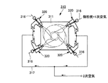
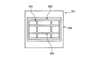
- FIG. 25 is a diagram showing Example 12 for a solid fuel burning (coal fuel burning) burner according to the present invention, (a) is a front view of the solid fuel burning burner as seen from inside a furnace, and (b) is (a).
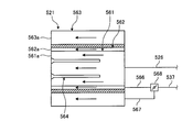
- FIG. 2 is a cross-sectional view of the solid fuel burning burner taken along the line AA (a longitudinal sectional view of the solid fuel burning burner).
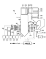
- FIG. 26 is a diagram showing an air supply system that supplies air to the solid fuel burning burner of FIG.
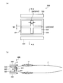
- FIG. 27 is a longitudinal sectional view showing a configuration example of a solid fuel burning (coal burning) boiler according to the present invention.
- FIG. 28 is a horizontal (horizontal) cross-sectional view of FIG.
- FIG. 29 is an explanatory diagram showing an outline of a solid fuel-fired boiler that includes an additional air input unit and that inputs air in multiple stages.
- 30A is a diagram showing an example of a cross-sectional shape of the split member of the solid fuel burning burner shown in FIG. 25, FIG.
- FIG. 30B is a diagram showing a first modification of the cross-sectional shape, and FIG. The figure which shows this 2nd modification, (d) is a figure which shows the 3rd modification of a cross-sectional shape.
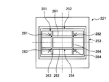
- FIG. 31 is a view showing Example 14 for a solid fuel burning (coal fuel burning) burner according to the present invention, (a) is a front view of the solid fuel burning burner as seen from inside a furnace, and (b) is (a).
- FIG. 2 is a cross-sectional view of the solid fuel burning burner shown in FIG. 32A is a cross-sectional view taken along the line CC of FIG. 31A showing one shape example of the shielding member, and FIG. 32B is a cross-sectional view showing another shape example of the shielding member shown in FIG.
- FIG. 33 is a view showing Example 15 of a solid fuel burning (coal fuel burning) burner for a swirl combustion boiler according to the present invention, (a) is a front view of the solid fuel burning burner as seen from inside a furnace, ) Is an AA cross-sectional view (a vertical cross-sectional view of the solid fuel-burning burner) of the solid fuel-burning burner shown in FIG.
- FIG. 34 is a diagram showing an air supply system that supplies air to the solid fuel burning burner of FIG.
- FIG. 35 is a longitudinal sectional view showing a configuration example of a solid fuel fired boiler (coal fired boiler) according to the present invention.
- 36 is a horizontal (horizontal) cross-sectional view of FIG. FIG.
- FIG. 37 is an explanatory diagram showing an outline of a solid fuel-fired boiler that is provided with an additional air input unit and that inputs air in multiple stages.
- FIG. 38 is a diagram showing an example of a cross-sectional shape of the split member of the solid fuel burning burner shown in FIG. 33, (b) a diagram showing a first modification of the cross-sectional shape, and (c) a cross-sectional shape. The figure which shows this 2nd modification, (d) is a figure which shows the 3rd modification of a cross-sectional shape.
- FIG. 39 is a schematic configuration diagram illustrating a pulverized coal burning boiler as a boiler according to Embodiment 17 of the present invention.
- FIG. 40 is a plan view showing a combustion burner in the pulverized coal burning boiler of Example 17.
- FIG. 41 is a front view illustrating the combustion burner according to the seventeenth embodiment.
- FIG. 42 is a cross-sectional view illustrating a combustion burner according to the seventeenth embodiment.
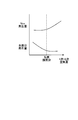
- FIG. 43 is a graph showing the NOx generation amount and the unburned component generation amount for the primary air and the secondary air.
- Patent Document 1 As a combustion burner of a conventional pulverized coal fired boiler, there is one described in Patent Document 1 described above.
- the combustion apparatus described in Patent Document 1 by providing a flame holder between the center inside the pulverized coal injection hole (primary flow path) and the outer peripheral portion, the pulverized coal concentrated flow is supplied to the flame holder. It is made to collide and enables stable low NOx combustion over a wide load range.
- Embodiment 1 solves this problem and aims to provide a combustion burner capable of realizing an appropriate flow of fuel gas in which solid fuel and air are mixed.
- FIG. 1 is a front view illustrating a combustion burner according to a first embodiment of the present invention
- FIG. 2 is a cross-sectional view illustrating the combustion burner according to the first embodiment
- FIGS. 3 and 4 are modifications of the combustion burner according to the first embodiment.
- FIG. 5 is a front view showing a modification of the combustion burner of the first embodiment
- FIGS. 6 and 7 are sectional views showing a modification of the combustion burner of the first embodiment
- FIG. FIG. 9 is a schematic configuration diagram showing a pulverized coal burning boiler to which the combustion burner of the first embodiment is applied
- FIG. 10 is a combustion in the pulverized coal burning boiler of the first embodiment. It is a top view showing a burner.
- the pulverized coal fired boiler to which the combustion burner of Example 1 is applied can use the pulverized coal obtained by pulverizing coal as a solid fuel, burn the pulverized coal with the combustion burner, and recover the heat generated by the combustion. Boiler.
- the pulverized coal burning boiler 10 is a conventional boiler, and includes a furnace 11 and a combustion device 12.
- the furnace 11 has a rectangular hollow shape and is installed along the vertical direction.
- a combustion device 12 is provided at the lower part of the furnace wall constituting the furnace 11.
- the combustion apparatus 12 has a plurality of combustion burners 21, 22, 23, 24, and 25 attached to the furnace wall.
- the combustion burners 21, 22, 23, 24, and 25 are arranged as four sets at equal intervals along the circumferential direction, and 5 sets along the vertical direction. Five stages are arranged.
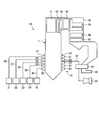
- Each combustion burner 21, 22, 23, 24, 25 is connected to a pulverized coal machine (mill) 31, 32, 33, 34, 35 via a pulverized coal supply pipe 26, 27, 28, 29, 30. ing.
- the pulverized coal machines 31, 32, 33, 34, and 35 are supported in a housing so that the pulverization table can be driven to rotate with a rotation axis along the vertical direction, and face the upper side of the pulverization table.
- a plurality of crushing rollers are configured to be rotatably supported in conjunction with the rotation of the crushing table.
- the pulverized coal supplied to the pulverized coal supply pipes 26 and 27 is pulverized to a predetermined size and classified by carrier air (primary air). , 28, 29, 30 can be supplied to the combustion burners 21, 22, 23, 24, 25.
- the furnace 11 is provided with a wind box 36 at the mounting position of each combustion burner 21, 22, 23, 24, 25, and one end portion of an air duct 37 is connected to the wind box 36, and this air
- the duct 37 has a blower 38 attached to the other end. Therefore, the combustion air (secondary air and tertiary air) sent by the blower 38 is supplied from the air supply pipe 37 to the wind box 36, and the combustion burners 21, 22, 23, 24, 25.
- each combustion burner 21, 22, 23, 24, 25 can blow a pulverized fuel mixture (fuel gas) obtained by mixing pulverized coal and primary air into the furnace 11. Secondary air can be blown into the furnace 11, and a flame can be formed by igniting the pulverized fuel mixture with an ignition torch (not shown).
- a pulverized fuel mixture fuel gas obtained by mixing pulverized coal and primary air into the furnace 11.
- Secondary air can be blown into the furnace 11, and a flame can be formed by igniting the pulverized fuel mixture with an ignition torch (not shown).
- each combustion burner 21, 22, 23, 24, 25 injects oil fuel into the furnace 11 to form a flame.
- the furnace 11 has a flue 40 connected to the upper portion thereof, and a superheater (superheater) 41 and 42 for recovering heat of exhaust gas as a convection heat transfer section, and a reheater 43 and 44 in the flue 40.
- the economizers 45, 46 and 47 are provided, and heat exchange is performed between the exhaust gas generated by the combustion in the furnace 11 and water.
- the flue 40 is connected to an exhaust gas pipe 48 through which exhaust gas subjected to heat exchange is discharged downstream.
- This exhaust gas pipe 48 is provided with an air heater 49 between the air duct 37 and performs heat exchange between the air flowing through the air duct 37 and the exhaust gas flowing through the exhaust gas pipe 48, and the combustion burners 21, 22, 23, The temperature of the combustion air supplied to 24 and 25 can be raised.
- the exhaust gas pipe 48 is provided with a denitration device, an electrostatic precipitator, an induction blower, and a desulfurization device, and a chimney is provided at the downstream end.
- the generated pulverized coal together with the conveying air passes through the pulverized coal supply pipes 26, 27, 28, 29, and 30 and the combustion burners 21, 22, 23, 24, 25. Also, heated combustion air is supplied from the air duct 37 to the combustion burners 21, 22, 23, 24, 25 via the wind box 36. Then, the combustion burners 21, 22, 23, 24, and 25 blow the pulverized fuel mixture mixed with the pulverized coal and the carrier air into the furnace 11 and blow the combustion air into the furnace 11 and ignite at this time. Can form a flame. In the furnace 11, the pulverized fuel mixture and the combustion air are burned to generate a flame. When a flame is generated in the lower part of the furnace 11, the combustion gas (exhaust gas) rises in the furnace 11, and the flue 40 is discharged.
- exhaust gas exhaust gas
- the interior is maintained in a reducing atmosphere by setting the air supply amount to be less than the theoretical air amount with respect to the pulverized coal supply amount. Then, NOx generated by the combustion of the pulverized coal is reduced in the furnace 11, and then additional air is supplied to complete the oxidation combustion of the pulverized coal, thereby reducing the amount of NOx generated by the combustion of the pulverized coal. .
- the exhaust gas that has passed through the economizers 45, 46, and 47 of the flue 40 is subjected to removal of harmful substances such as NOx by a catalyst in a denitration device (not shown) in the exhaust gas pipe 48, and the particulate matter is collected by an electric dust collector Is removed, and after the sulfur content is removed by the desulfurizer, it is discharged from the chimney into the atmosphere.
- combustion apparatus 12 since each combustion burner 21, 22, 23, 24, 25 which comprises this combustion apparatus 12 has comprised the substantially the same structure, it is located in the uppermost stage. Only the combustion burner 21 will be described.
- the combustion burner 21 is composed of combustion burners 21 a, 21 b, 21 c, and 21 d provided on four wall surfaces in the furnace 11.
- Each combustion burner 21a, 21b, 21c, 21d is connected to each branch pipe 26a, 26b, 26c, 26d branched from the pulverized coal supply pipe 26, and each branch pipe 37a, 37b, 37c branched from the air duct 37. , 37d are connected.
- each combustion burner 21a, 21b, 21c, 21d on each wall surface of the furnace 11 blows into the furnace 11 a pulverized fuel mixture in which pulverized coal and carrier air are mixed, and the pulverized fuel mixture Blow combustion air to the outside. Then, by igniting the pulverized fuel mixture from each combustion burner 21a, 21b, 21c, 21d, four flames F1, F2, F3, F4 can be formed, and this flame F1, F2, F3, F4. Is a flame swirl flow swirling counterclockwise as viewed from above the furnace 11 (in FIG. 10).
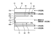
- the fuel nozzle 51, the secondary air nozzle 52, and the tertiary air nozzle are arranged from the center side. 53 and a flame holder 54 are provided.
- the fuel nozzle 51 is capable of blowing a fuel gas (a fine fuel mixture) obtained by mixing pulverized coal (solid fuel) and carrier air (primary air).
- the secondary air nozzle 52 is disposed outside the first nozzle 51 and can blow combustion air (secondary air) into the outer peripheral side of the fuel gas injected from the fuel nozzle 51.
- the tertiary air nozzle 53 is disposed outside the secondary air nozzle 52 and can blow tertiary air into the outer peripheral side of the secondary air injected from the secondary air nozzle 52.
- the flame holder 54 is disposed in the fuel nozzle 51 at the downstream side in the fuel gas blowing direction and at the axial center, thereby functioning for ignition of the fuel gas and flame holding. To do.
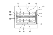
- This flame holder 54 is a so-called so-called “flame shape” in which first flame holding members 61 and 62 along the horizontal direction and second flame holding members 63 and 64 along the vertical direction (vertical direction) are arranged in a cross shape. It has a double cross split structure.
- Each first flame holding member 61, 62 has a flat portion 61a, 62a having a flat plate shape and a front end portion (downstream end portion in the fuel gas flow direction) of the flat portions 61a, 62a.
- widened portions 61b and 62b which are integrally provided.
- the widened portions 61b and 62b have an isosceles triangular cross section, the width increases toward the downstream side in the fuel gas flow direction, and the front end is a plane perpendicular to the fuel gas flow direction.
- the second flame holding members 63 and 64 have the same structure.
- the fuel nozzle 51 and the secondary air nozzle 52 have a long tubular structure, the fuel nozzle 51 has a rectangular opening 51a, and the secondary air nozzle 52 has a rectangular ring-shaped opening. Since it has 52a, the fuel nozzle 51 and the secondary air nozzle 52 have a double tube structure.
- a tertiary air nozzle 53 is arranged as a double pipe structure outside the fuel nozzle 51 and the secondary air nozzle 52, and has a rectangular ring-shaped opening 53a.
- the opening 52a of the secondary air nozzle 52 is disposed outside the opening 51a of the fuel nozzle 51
- the opening 53a of the tertiary air nozzle 53 is disposed outside the opening 52a of the secondary air nozzle 52. It will be arranged.
- the tertiary air nozzle 53 may be a tertiary air nozzle by arranging a plurality of nozzles separately on the outer peripheral side of the secondary air nozzle 52 without being arranged as a double tube structure.
- nozzles 51, 52, 53 are arranged with openings 51a, 52a, 53a aligned on the same plane.
- the flame holder 54 is supported by a plate material (not shown) from the inner wall surface of the fuel nozzle 51 or the upstream side of the flow path through which the fuel gas flows. Further, since the fuel nozzle 51 has a plurality of flame holding members 61, 62, 63, 64 as flame holders 54 disposed therein, the fuel gas flow path is divided into nine. Become. In the flame holder 54, the widened portions 61b and 62b whose widths are widened at the front end portions are located, and the widened portions 61b and 62b have the front end surfaces aligned on the same plane as the opening 51a.
- a rectifying member 55 is provided between the inner wall surface of the fuel nozzle 51 and the flame holder 54.
- the rectifying member 55 has a predetermined gap with the inner wall surface of the fuel nozzle 51 and is disposed with a predetermined gap with the flame holder 54.
- the rectifying member 55 has a structure in which the first rectifying members 65 and 66 along the horizontal direction and the second rectifying members 67 and 68 along the vertical direction (vertical direction) are arranged in a frame shape. is there. That is, the first rectifying member 65 is positioned between the upper wall of the fuel nozzle 51 and the first flame holding member 61, and the first rectifying member 66, the lower wall of the fuel nozzle 51, the first flame holding member 62, Located between.
- the second rectifying member 67 is located between the side wall (left wall in FIG. 1) of the fuel nozzle 51 and the second flame holding member 63, and the second rectifying member 68 is the side wall (see FIG. 1 is located between the right wall) and the second flame holding member 64.
- straightening members 65 and 66 are flat part 65a, 66a which makes the flat shape with the constant thickness, and the front-end part (downstream end part of the flow direction of fuel gas) of this flat part 65a, 66a. It has the taper details 65b and 66b provided integrally.
- the tapered portions 65b and 66b have an isosceles triangular cross section, the width becomes narrower toward the downstream side in the fuel gas flow direction, and the front end has an acute angle.
- the second rectifying members 67 and 68 have the same structure.
- each flame-holding member 61, 62, 63, 64 and each rectifying member 65, 66, 67, 68 have substantially the same length in the fuel gas flow direction, and are orthogonal to the fuel gas flow direction. It is arranged facing the direction.
- Each of the flame holding members 61, 62, 63, 64 and each of the rectifying members 65, 66, 67, 68 has the widened portions 61b, 62b and the tapered portions 65b, 66b, which are almost equal in length in the fuel gas flow direction. It is the same, and is arrange
- the flame stabilizer 54 and the rectifying member 55 are provided with the above-described widened portions 61b and 62b and the tapered portions 65b and 66b, they are orthogonal to the flow direction of the fuel gas in the flame holder 54 and the rectifying member 55. The distance in the direction in which the gas flows is almost the same along the flow direction of the fuel gas.
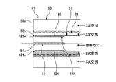
- the fuel gas obtained by mixing pulverized coal and primary air is blown into the furnace from the opening 51 a of the fuel nozzle 51, and the secondary air is discharged from the secondary air nozzle 52 on the outside thereof.
- the air is blown into the furnace through the opening 52 a, and the tertiary air is blown into the furnace through the opening 53 a of the tertiary air nozzle 53 on the outside thereof.
- the fuel gas is branched and ignited by the flame holder 54 at the opening 51a of the fuel nozzle 51, and burns to become a combustion gas.
- combustion of fuel gas is accelerated
- the ratio of the secondary air and the tertiary air can be adjusted to obtain optimum combustion.
- the flame holder 54 has a split shape, the fuel gas is branched by the flame holder 54 at the opening 51 a of the fuel nozzle 51. At this time, the flame holder 54 is moved to the fuel nozzle 51. In the central region of the opening 51a, ignition and flame holding of the fuel gas are performed in this central region. Thereby, the internal flame holding of the combustion flame (flame holding in the central region of the opening 51a of the fuel nozzle 51) is realized.
- the outer peripheral portion of the combustion flame becomes low temperature, and the temperature of the outer peripheral portion of the combustion flame in a high oxygen atmosphere can be lowered by the secondary air. The amount of NOx generated at the outer periphery is reduced.
- the combustion burner 21 since the combustion burner 21 employs a structure that holds the internal flame, it is preferable that the fuel gas and the combustion air (secondary air and tertiary air) are supplied as a straight flow. That is, it is preferable that the fuel nozzle 51, the secondary air nozzle 52, and the tertiary air nozzle 53 have a structure that supplies the fuel gas, the secondary air, and the tertiary air as a straight flow without swirling. Since the fuel gas, the secondary air, and the tertiary air are injected as a straight flow to form a combustion flame, the gas circulation in the combustion flame is suppressed in the configuration in which the combustion flame is held inside. Thereby, the outer peripheral part of a combustion flame is maintained with low temperature, and the NOx generation amount by mixing with secondary air is reduced.
- the fuel gas and the combustion air secondary air and tertiary air
- a rectifying member 55 is provided between the fuel nozzle 51 and the flame holder 54 with a predetermined gap therebetween. Therefore, in particular, the fuel gas flowing between the flame holder 54 and the rectifying member 55 is rectified, so that the fuel gas does not peel off at the rear end portion of the flame holder 54, and the fuel gas directed toward the tip portion disappears. Since a flow is formed, the flame holder 54 can secure a sufficient flame holding force at the tip.
- widening portions 61 b and 62 b are provided at the front end portion of the flame holder 54, and tapered portions 65 b and 66 b are provided at the front end portion of the rectifying member 55, so that they are formed between the flame holder 54 and the rectifying member 55.
- the flow path is substantially the same in cross-sectional area in the longitudinal direction, the flow velocity of the fuel gas flowing therethrough is made uniform, and the flow velocity of the fuel gas is reduced as a whole. Can secure a sufficient flame holding power. Further, in the pulverized coal fired boiler, it is necessary to adjust the steam temperature and the exhaust gas characteristics, and it is possible to ensure internal flame holding by the rectifying member 55 also at that time.
- the structure of the flame holder 54 and the rectifying member 55 in the combustion burner 21 is not limited to the above-described embodiment.
- a fuel nozzle 51, a secondary air nozzle 52, and a tertiary air nozzle 53 are provided from the center side, and a flame holder 71 is provided.
- the flame holder 71 is disposed in the fuel nozzle 51 on the downstream side in the fuel gas blowing direction and on the axial center side, thereby functioning for ignition of the fuel gas and flame holding. Is.
- This flame holder 71 is a so-called double cross split in which first flame holding members 72 and 73 along the horizontal direction and second flame holding members (not shown) along the vertical direction are arranged in a cross shape. It is a structure.
- the first flame-holding members 72 and 73 have an isosceles triangular cross section and have a widened shape whose width increases toward the downstream side in the fuel gas flow direction, and the front end is in the fuel gas flow direction. It becomes a plane orthogonal to. Note that each second flame holding member has a similar structure.
- the fuel gas is branched by the flame holder 71 at the opening 51a of the fuel nozzle 51, so that the internal flame of the combustion flame can be obtained by wrapping around the front end surface side, and the secondary air is used in a high oxygen atmosphere.
- the temperature of the outer peripheral part of the combustion flame in the above becomes lower, and the amount of NOx generated in the outer peripheral part of the combustion flame is reduced.
- fuel gas flowing between the rectifying member 55 and the flame holder 71 is rectified, so that the fuel gas is not peeled off, and the flow rate of the fuel gas flowing therethrough is made uniform, and the flow rate is increased.
- the flame holder 71 can secure a sufficient flame holding force at the tip.
- a fuel nozzle 51, a secondary air nozzle 52, and a tertiary air nozzle 53 are provided from the center side, and a flame holder 54 is provided.
- a rectifying member 75 is provided between the inner wall surface of the fuel nozzle 51 and the flame holder 54.
- the rectifying member 75 has a predetermined gap with the inner wall surface of the fuel nozzle 51 and is disposed with a predetermined gap with the flame holder 54. That is, the rectifying member 75 has a structure in which the first rectifying members 76 and 77 along the horizontal direction and the second rectifying member (not shown) along the vertical direction (vertical direction) are arranged in a frame shape. It is.
- Each of the first rectifying members 76 and 77 has a flat plate shape with a constant thickness.
- Each second rectifying member has the same structure.
- the flow straightening members 76 and 77 are slightly shorter in the flow direction of the fuel gas than the flame holding members 61 and 62, and are arranged to face each other in the direction perpendicular to the flow direction of the fuel gas. Yes.
- the flat portions 61a and 62a of the flame holding members 61 and 62 and the rectifying members 76 and 77 have substantially the same length in the fuel gas flow direction.
- the flame stabilizer 54 and the rectifying member 75 have a shape in which the above-described widened portions 61b and 62b are provided, the distance in the direction perpendicular to the fuel gas flow direction in the flame holder 54 and the rectifying member 75 is It is almost the same along the flow direction of the fuel gas.
- the flame holder 54 is provided with widened portions 61b and 62b on the downstream side in the fuel gas flow direction, while the rectifying member 75 is provided at a position not facing the widened portions 61b and 62b.
- the fuel gas is branched by the flame holder 54 at the opening of the fuel nozzle 51, so that the internal flame of the combustion flame can be held by flowing around the front end face side, and the secondary air is brought into a high oxygen atmosphere.
- the temperature of the outer peripheral part of a certain combustion flame is lowered, and the amount of NOx generated in the outer peripheral part of the combustion flame is reduced.
- the fuel gas flowing between the rectifying member 75 and the flame holder 54 is rectified, so that the fuel gas is not peeled off, and the flow rate of the fuel gas flowing therethrough is made uniform so that the flow rate is increased.
- the flame holder 54 can secure a sufficient flame holding force at the tip.
- a fuel nozzle 51, a secondary air nozzle 52, and a tertiary air nozzle 53 are provided from the center side, and a flame holder 81 is provided.
- a rectifying member 55 is provided between the inner wall surface of the fuel nozzle 51 and the flame holder 81.
- the flame holder 81 is disposed in the fuel nozzle 51 on the downstream side in the fuel gas blowing direction and on the axial center side, thereby functioning for ignition of the fuel gas and flame holding. Is.
- This flame holder 81 has a so-called double cross split structure in which first flame holding members 82 and 83 along the horizontal direction and second flame holding members 84 and 85 along the vertical direction are arranged in a cross shape. It is what makes.
- the first flame holding members 82 and 83 are set to have a larger width than the second flame holding members 84 and 85.
- the fuel gas is branched by the flame holder 81 at the opening 51 a of the fuel nozzle 51, so that the combustion gas can be held inside by wrapping around the front end face side, and the secondary air is used in a high oxygen atmosphere.
- the temperature of the outer peripheral part of the combustion flame in the above becomes lower, and the amount of NOx generated in the outer peripheral part of the combustion flame is reduced.
- the first flame holding members 82 and 83 are wider than the second flame holding members 84 and 85, the first flame holding members 82 and 83 are higher than the second flame holding members 84 and 85.
- the burner 21 of the present embodiment is a swirl combustion method, and since air is supplied from above and below the fuel gas, it is effective to ensure a high flame holding capability in the horizontal direction for internal flame holding.
- the wide first flame holding members 82 and 83 are arranged.
- 83 makes it possible to improve the flame holding function in the horizontal direction.
- a fuel nozzle 51, a secondary air nozzle 52, and a tertiary air nozzle 53 are provided from the center side, and a flame holder 91 is provided.
- the flame holder 91 is disposed in the fuel nozzle 51 on the downstream side in the fuel gas blowing direction and on the axial center side, thereby functioning for ignition of the fuel gas and flame holding. Is.
- This flame holder 91 is a so-called double cross split in which first flame holding members 92 and 93 along the horizontal direction and second flame holding members (not shown) along the vertical direction are arranged in a cross shape. It is a structure.
- the first flame holding members 92 and 93 include flat portions 92a and 93a, widened portions 92b and 93b, and tapered portions 92c and 93c.
- the tapered portions 92c and 93c are provided at the rear end portion. The width is narrower toward the upstream side in the flow direction of the fuel gas. Note that each second flame holding member has a similar structure.
- a rectifying member 95 is provided between the inner wall surface of the fuel nozzle 51 and the flame holder 91.
- the rectifying member 95 has a predetermined gap from the inner wall surface of the fuel nozzle 51 and is arranged with a predetermined gap from the flame holder 91. That is, the rectifying member 95 has a structure in which the first rectifying members 96 and 97 along the horizontal direction and the second rectifying member (not shown) along the vertical direction (vertical direction) are arranged in a frame shape. It is.
- Each of the first rectifying members 96 and 97 has flat portions 96a and 97a, tapered portions 96b and 97b, and tapered portions 96c and 97c, and the tapered portions 96c and 97c are provided at the rear end portion. The width is narrower toward the upstream side in the flow direction of the fuel gas.
- Each second rectifying member has the same structure.
- the fuel gas is branched by the flame holder 91 at the opening 51a of the fuel nozzle 51, so that the internal flame of the combustion flame can be obtained by wrapping around the front end face side, and the secondary air is used in a high oxygen atmosphere.
- the temperature of the outer peripheral part of the combustion flame in the above becomes lower, and the NOx generation amount in the outer peripheral part of the combustion flame is reduced.
- the fuel gas flowing between the flame stabilizer 91 is rectified by the rectifying member 95, so that the fuel gas is not separated, and the flow rate of the fuel gas flowing therethrough is made uniform so that the flow rate is increased.
- this flame holder 91 can ensure a sufficient flame holding force at the tip.
- the flame stabilizer 91 and the rectifying member 95 are provided with the tapered portions 92c, 93c, 96c, and 97c, the fuel gas smoothly flows along the flame holder 91 and the rectifying member 95, and the peeling is performed. Is suppressed.
- a fuel nozzle 51, a secondary air nozzle 52, and a tertiary air nozzle 53 are provided from the center side, and a flame holder 54 is provided.
- a rectifying member 101 is provided between the inner wall surface of the fuel nozzle 51 and the flame holder 54.
- the flow regulating member 101 has a predetermined gap with the inner wall surface of the fuel nozzle 51 and is disposed with a predetermined gap with the flame holder 54. That is, the straightening member 101 has a structure in which the first straightening members 102 and 103 along the horizontal direction and the second straightening member (not shown) along the vertical direction (vertical direction) are arranged in a frame shape. It is.
- the first rectifying members 102 and 103 are widened integrally provided at the flat portions 102a and 103a having a flat plate shape with a constant thickness and the front end portions (downstream end portions in the fuel gas flow direction). Parts 102b and 103b. Each second rectifying member has the same structure.
- the flow straightening members 102 and 103 are slightly shorter in the flow direction of the fuel gas than the flame holding members 61 and 62, and are arranged to face each other in a direction perpendicular to the flow direction of the fuel gas. Yes. That is, the flat portions 61a and 62a of the flame holding members 61 and 62 and the rectifying members 102 and 103 have substantially the same length in the fuel gas flow direction.
- the fuel gas is branched by the flame holder 54 at the opening of the fuel nozzle 51, so that the internal flame of the combustion flame can be held by flowing around the front end face side, and the secondary air is brought into a high oxygen atmosphere.
- the temperature of the outer peripheral part of a certain combustion flame is lowered, and the amount of NOx generated in the outer peripheral part of the combustion flame is reduced.
- the fuel gas flowing between the rectifying member 101 and the flame holder 54 is rectified, so that the separation of the fuel gas is eliminated, and the flow rate of the fuel gas flowing therethrough is made uniform so that the flow rate is increased.
- the flame holder 54 can secure a sufficient flame holding force at the tip.
- the flow straightening member 101 is shorter than the flame holder 54, even if the widened portions 102b and 103b are provided at the tip portion to provide a flame holding function, the passage area of the fuel nozzle 51 is not extremely narrowed.
- the flame holding power can be improved, and even a flame-retardant fuel can be stably burned.
- a fuel nozzle 111, a secondary air nozzle 112, and a tertiary air nozzle 113 are provided from the center side, and a flame holder 114 is provided.
- a rectifying member 115 is provided between the inner wall surface of the fuel nozzle 111 and the flame holder 114.
- the fuel nozzle 111 has a circular opening, and the secondary air nozzle 112 and the tertiary air nozzle 113 similarly have a cylindrical shape.
- Such a configuration is particularly applied to a configuration in which the combustion burners 21 are arranged to face each other.
- the flame holder 114 is disposed in the fuel nozzle 111 at the downstream side in the fuel gas blowing direction and at the axial center side, thereby functioning for ignition of the fuel gas and flame holding. It is.
- the flame holder 114 is arranged so as to intersect two flame holding members along the horizontal direction and two flame holding members along the vertical direction.
- the flow regulating member 115 has a predetermined gap with the inner wall surface of the fuel nozzle 111 and is disposed with a predetermined gap with the flame holder 114. That is, the rectifying member 115 has a structure in which two rectifying members along the horizontal direction and two rectifying members along the vertical direction are arranged in a frame shape.
- the fuel gas is branched by the flame holder 114 at the opening of the fuel nozzle 111, so that the internal flame of the combustion flame can be held by wrapping around the front end face side, and the secondary air is brought into a high oxygen atmosphere.
- the temperature of the outer peripheral part of a certain combustion flame is lowered, and the amount of NOx generated in the outer peripheral part of the combustion flame is reduced.
- the fuel gas flowing between the flame stabilizer 114 is rectified by the rectifying member 115, so that the fuel gas is not peeled off, and the flow rate of the fuel gas flowing therethrough is made uniform so that the flow rate is increased.
- this flame holder 114 can secure a sufficient flame holding force at the tip.
- the fuel nozzle 51 capable of injecting the fuel gas in which the pulverized coal and the primary air are mixed, and the secondary air 2 can be injected from the outside of the fuel nozzle 51.
- a secondary air nozzle 52 is provided, a flame holder 54 is provided on the axial center side at the tip of the fuel nozzle 51, and a rectifying member 55 is provided between the inner wall surface of the fuel nozzle 51 and the flame holder 54. .
- the rectifying member 55 between the inner wall surface of the fuel nozzle 51 and the flame holder 54, the flow of the fuel gas flowing through the fuel nozzle 51 is rectified by the rectifying member 55, and the flame holder 54.
- the separation of the fuel gas flow at the rear end of the fuel nozzle 51 is suppressed, and the flow velocity is substantially constant, and the pulverized coal fuel is suppressed from being deposited (or adhered) on the inner wall surface of the fuel nozzle 51.
- a proper flow of fuel gas can be realized.
- the rectifying member 55 is arranged with a predetermined gap from the flame holder 54. Therefore, by ensuring a predetermined gap between the flow straightening member 55 and the flame holder 54, the flow of the fuel gas flowing between the flow straightening member 55 and the flame holder 54 is rectified, and the flame holder. Therefore, the flame holding function of the flame holder 54 can be sufficiently exhibited.
- the distance between the flame holder 54 and the rectifying member 55 is set to be substantially the same along the fuel gas flow direction by the rectifying member 55. Therefore, the flow rate of the fuel gas flowing between the rectifying member 55 and the flame holder 54 is approximately the same as the distance from the flame holder 54 by the rectifying member 55 along the flow direction of the fuel gas. As a result, the accumulation of the pulverized coal fuel at the fuel nozzle 51 and the adhesion of the pulverized coal fuel to the flame holder 54 can be suppressed.
- the widening portions 61b and 62b are provided on the downstream side in the fuel gas flow direction in the flame holder 54, while the tapered portions 65b and 62b are provided on the downstream side in the fuel gas flow direction in the rectifying member 55.
- 66b is provided. Therefore, by providing the widened portions 61b and 62b at the tip of the flame holder 54, it is possible to achieve reliable flame holding, while by providing the tapered portions 65b and 66b at the tip of the rectifying member 55, The distance between the flame unit 54 and the rectifying member 55 can be made substantially constant in the fuel gas flow direction.
- the flame holder 54 is arranged along the vertical direction with the two first flame holding members 61 and 62 that are parallel with a predetermined gap in the vertical direction along the horizontal direction.
- the second flame holding members 63 and 64 that are parallel with a predetermined gap in the horizontal direction are arranged so as to intersect each other. Therefore, it is possible to ensure a sufficient flame holding function by making the flame holder 54 have a double cross structure.
- the widening portions 61b and 62b are provided on the downstream side in the fuel gas flow direction in the flame holder 54, while the rectifying member 75 is opposed to the widening portion widening portions 61b and 62b. It is provided at a position that does not. Therefore, the flow path of the fuel gas between the widened portions 61b and 62b of the flame holder 54 and the fuel nozzle 51 is narrowed by providing the rectifying member 75 at a position not facing the widened portions 61b and 62b of the flame holder 54. In other words, the flow rate of the fuel gas is substantially constant, and the accumulation of the pulverized coal fuel at the fuel nozzle 51 and the adhesion of the pulverized coal fuel to the flame holder 54 can be suppressed.
- FIG. 11 is a cross-sectional view showing a combustion burner according to Embodiment 2 of the present invention.
- symbol is attached
- the combustion burner 21 is provided with a fuel nozzle 51, a secondary air nozzle 52, and a tertiary air nozzle 53 from the center side, and a flame holder. 121 is provided.
- a rectifying member 122 is provided between the inner wall surface of the fuel nozzle 51 and the flame holder 121.
- the flame holder 121 is arranged in the horizontal direction along the axial center of the fuel nozzle 51, and the configuration thereof is substantially the same as the first flame holding members 61 and 62 described in the first embodiment. ing.
- the flame holder 121 has a widened portion whose width increases toward the downstream side in the fuel gas flow direction, and the front end is a plane perpendicular to the fuel gas flow direction.
- the rectifying member 122 is fixed along the inner wall surface of the fuel nozzle 51 so as to be arranged with a predetermined gap from the flame holder 121. That is, the rectifying member 122 includes first rectifying members 123 and 124 that extend in the horizontal direction, and an inclined portion 123a that vertically opposes the widened portion of the flame holder 121 at the downstream end in the fuel gas flow direction. , 124a are provided. In this case, the first rectifying members 123 and 124 are directly fixed to the inner wall surface of the fuel nozzle 51, but a supporting member may be extended from the upstream portion of the fuel nozzle 51 to support the first rectifying members 123 and 124. .
- the flame holder 121 and the rectifying member 122 have a shape in which the above-described widened portion and the inclined portions 123a and 124a are provided facing each other, and are orthogonal to the fuel gas flow direction in the flame holder 121 and the rectifying member 122.
- the distance in the direction is substantially the same along the flow direction of the fuel gas.
- the fuel gas is branched by the flame holder 121 at the opening 51a of the fuel nozzle 51, so that the combustion gas can be held inside by being circulated toward the front end face side, and the secondary air can be used in a high oxygen atmosphere.
- the temperature of the outer peripheral part of the combustion flame in the above becomes lower, and the NOx generation amount in the outer peripheral part of the combustion flame is reduced.
- the fuel gas flowing between the rectifying member 122 and the flame holder 121 is rectified, so that the fuel gas is not peeled off, and the flow rate of the fuel gas flowing therethrough is made uniform so that the flow rate is increased.
- the flame holder 121 can ensure a sufficient flame holding force at the tip.
- the rectifying member 122 is provided on the inner wall surface of the fuel nozzle 51. Therefore, by providing the rectifying member 122 on the inner wall surface of the fuel nozzle 51, it is possible to easily support the rectifying member 122 without using an attachment member or the like, and to improve the assembling property of the rectifying member 122. And manufacturing cost can be reduced. Further, the mixing of the secondary air can be delayed, and the high temperature and high oxygen region on the outer periphery can be reduced.
- FIG. 12 is a cross-sectional view showing a combustion burner according to Embodiment 3 of the present invention.
- symbol is attached
- the combustion burner 21 is provided with a fuel nozzle 51, a secondary air nozzle 52, and a tertiary air nozzle 53 from the center side, and a flame stabilizer. 131 is provided.
- a rectifying member 135 is provided inside the flame holder 131.
- the flame holder 131 is arranged along the horizontal direction at the axial center of the fuel nozzle 51, and is arranged so as to intersect two flame holding members along the horizontal direction and two flame holding members along the vertical direction.
- the rectifying member 135 is located between the flame holding members in the flame holder 131 and intersects the horizontal direction and the vertical direction to form a cross shape, and the flame holder 131 and the rectifying member 136. It has 2nd rectification
- the first rectifying member 136 is fixed to the inner wall surface of the fuel nozzle 51 so as to be arranged with a predetermined gap from the flame holder 131. Further, the second rectifying members 137 and 138 are fixed to the inner wall surface of the fuel nozzle 51 on the upstream side of the fuel gas from the flame holder 131, and guide the fuel gas flowing through the fuel nozzle 51 to the center side thereof. be able to.
- the flame holder 132 can secure a sufficient flame holding force at the tip.
- the first rectifying member 136 having a cross shape located inside the flame holder 131 and the upstream side of the flame holder 131 is located.
- Second rectifying members 137 and 138 are provided. Therefore, the fuel gas flowing in the fuel nozzle 51 is guided to the center of the fuel nozzle 51 by the second rectifying members 137 and 138, and the flow is rectified by the first rectifying member 136. Appropriate flow can be realized.
- FIG. 13 is a cross-sectional view showing a combustion burner according to Example 4 of the present invention.
- symbol is attached
- the combustion burner 21 is provided with a fuel nozzle 51, a secondary air nozzle 52, and a tertiary air nozzle 53 from the center side, and a flame holder. 54 is provided.
- a rectifying member 141 is provided inside the flame holder 54.
- the flame holder 131 is disposed along the horizontal direction at the axial center of the fuel nozzle 51.
- the flow regulating member 141 has a cross shape that intersects the horizontal direction and the vertical direction inside the flame holder 54. In this case, the rectifying member 141 has a tip portion located upstream from the flame holder 54.
- the fuel gas is branched by the flame holder 54 at the fuel nozzle 51, so that the combustion flame can be held inside by flowing around the front end face side, and the combustion flame in a high oxygen atmosphere by the secondary air.
- the temperature of the outer peripheral portion of the fuel becomes lower, and the amount of NOx generated in the outer peripheral portion of the combustion flame is reduced.
- the fuel gas flowing between the flame stabilizer 54 and the flame stabilizer 54 is rectified by the rectifying member 141, so that the fuel gas is not peeled off.
- the flame holder 54 can secure a sufficient flame holding force at the tip.
- the rectifying member 141 is provided inside the flame holder 54 so as to be fixed to the inner wall surface of the fuel nozzle 51. Therefore, the flow of the fuel gas flowing in the fuel nozzle 51 is rectified by the rectifying member 141, and an appropriate flow of the fuel gas can be realized.
- FIG. 14 is a cross-sectional view showing a combustion burner according to Embodiment 5 of the present invention.
- symbol is attached
- the combustion burner 21 is provided with a fuel nozzle 51, a secondary air nozzle 52, and a tertiary air nozzle 53 from the center side, and a flame holder. 121 is provided.
- a rectifying member 151 is provided between the inner wall surface of the fuel nozzle 51 and the flame holder 121.
- the flame holder 121 is arranged in the horizontal direction along the axial center of the fuel nozzle 51, and the configuration thereof is substantially the same as the first flame holding members 61 and 62 described in the first embodiment. ing.
- the rectifying member 151 has a predetermined gap with the inner wall surface of the fuel nozzle 51 and is disposed with a predetermined gap with the flame holder 121. That is, the rectifying member 151 has a structure in which the first rectifying members 152 and 153 along the horizontal direction and the second rectifying member (not shown) along the vertical direction (vertical direction) are arranged in a frame shape. It is.
- straightening member 152,153 is inclined and arrange
- Each second rectifying member has the same structure.
- each rectifying member 152, 153 has a tip close to the flame holder 121, the gap between the rectifying members 152, 153 and the flame holder 121 becomes narrower toward the downstream side. Yes.
- the fuel gas is branched by the flame holder 121 at the opening of the fuel nozzle 51, so that the internal flame of the combustion flame can be held around the front end face side, and the secondary air is brought into a high oxygen atmosphere.
- the temperature of the outer peripheral part of a certain combustion flame is lowered, and the amount of NOx generated in the outer peripheral part of the combustion flame is reduced.
- the fuel gas flowing between the rectifying member 151 and the flame holder 121 is rectified, so that the separation of the fuel gas is eliminated, and the flow rate of the fuel gas flowing therethrough is made uniform so that the flow rate is increased.
- the flame holder 121 can ensure a sufficient flame holding force at the tip.
- the rectifying member 151 is provided outside the flame holder 121 so as to be fixed to the inner wall surface of the fuel nozzle 51, and the tip portion approaches the flame holder 121 side. It is inclined to. Therefore, the flow of the fuel gas flowing in the fuel nozzle 51 is rectified by the rectifying member 151, and an appropriate flow of the fuel gas can be realized.
- FIG. 15 is a cross-sectional view showing a combustion burner according to Embodiment 6 of the present invention.
- symbol is attached
- the combustion burner 21 is provided with a fuel nozzle 51, a secondary air nozzle 52, and a tertiary air nozzle 53 from the center side. 161 is provided.
- This flame holder 161 is a so-called double cross split in which first flame holding members 162 and 163 along the horizontal direction and second flame holding members (not shown) along the vertical direction are arranged in a cross shape. It is a structure.
- the first flame holding members 162 and 163 have a plate shape with a predetermined thickness. Note that each second flame holding member has a similar structure.
- the outer surfaces of the flame holding members 162 and 163 in the flame holder 161 function as rectifying members.
- the fuel gas is branched by the flame holder 161 at the opening 51a of the fuel nozzle 51, so that the combustion flame can be held inside by flowing around the front end surface side, and the secondary air can be used in a high oxygen atmosphere.
- the temperature of the outer peripheral part of the combustion flame in the above becomes lower, and the NOx generation amount in the outer peripheral part of the combustion flame is reduced.
- the fuel gas flowing between the fuel nozzle 51 and the flame holder 161 is rectified by the outer surface of the flame holder 161, so that the fuel gas is not peeled off, and the flow rate of the fuel gas flowing therethrough Is made uniform and the flow velocity is reduced, so that the flame holder 161 can secure a sufficient flame holding force at the tip.
- each flame holder has been described in various ways, but this configuration is not limited to that described above. That is, the burner of the present invention realizes internal flame holding, and it is sufficient that a flame holder is provided on the axial center side of the fuel nozzle, not the inner wall surface of the fuel nozzle. The position and the like may be appropriately set, and the flame holding member may be separated from the inner wall surface of the fuel nozzle. Moreover, although the structure of the rectification
- the combustion apparatus 12 is configured by arranging four combustion burners 21, 22, 23, 24, and 25 provided on the wall surface of the furnace 11 along the vertical direction. It is not limited to this configuration. That is, the combustion burner may be arranged at the corner without being arranged on the wall surface.
- the combustion apparatus is not limited to the swirl combustion method, and may be a front combustion method in which the combustion burner is disposed on one wall surface, or an opposed combustion method in which the combustion burner is disposed opposite to the two wall surfaces.
- the flame holder of the present invention is provided with the widened portion having a triangular cross-sectional shape.
- the present invention is not limited to this shape, and may have a rectangular shape or the widened portion may be eliminated.
- Patent Document 1 As a combustion burner of a conventional pulverized coal fired boiler, for example, there is one described in Patent Document 1 described above.
- the combustion apparatus described in Patent Document 1 by providing a flame holder between the center inside the pulverized coal injection hole (primary flow path) and the outer periphery, the pulverized coal concentrated flow collides with the flame holder.
- stable low NOx combustion is possible over a wide load range.
- the present invention solves the above-described problems, and an object of the present invention is to provide a combustion burner that can achieve a proper flow of fuel gas in which solid fuel and air are mixed to reduce the amount of NOx generated. .
- FIG. 16 is a front view showing a combustion burner according to a seventh embodiment of the present invention
- FIG. 17 is a sectional view showing the combustion burner of the seventh embodiment
- FIG. 18 is a pulverized coal to which the combustion burner of the seventh embodiment is applied.
- FIG. 19 is a schematic configuration diagram showing a burning boiler
- FIG. 19 is a plan view showing a combustion burner in the pulverized coal burning boiler of Example 7.
- the pulverized coal burning boiler to which the combustion burner of Example 7 is applied can use the pulverized coal obtained by pulverizing coal as a solid fuel, burn the pulverized coal with the combustion burner, and recover the heat generated by the combustion. Boiler.
- the pulverized coal fired boiler 210 is a conventional boiler, and includes a furnace 211 and a combustion device 212.
- the furnace 211 has a hollow shape of a square cylinder and is installed along the vertical direction, and a combustion device 212 is provided at the lower part of the furnace wall constituting the furnace 211.
- the combustion apparatus 212 has a plurality of combustion burners 221, 222, 223, 224, and 225 attached to the furnace wall.
- the combustion burners 221, 222, 223, 224, and 225 are arranged as four sets at equal intervals along the circumferential direction, and five sets along the vertical direction. Five stages are arranged.
- Each combustion burner 221, 222, 223, 224, 225 is connected to a pulverized coal machine (mill) 231, 232, 233, 234, 235 via a pulverized coal supply pipe 226, 227, 228, 229, 230. ing.
- the pulverized coal machines 231, 232, 233, 234, 235 are supported in a housing so that the grinding table can be driven to rotate with a rotation axis along the vertical direction, and face the upper side of the grinding table.
- a plurality of crushing rollers are configured to be rotatably supported in conjunction with the rotation of the crushing table.
- the pulverized coal supplied to the pulverized coal supply pipes 226 and 227 is pulverized to a predetermined size and classified by carrier air (primary air). , 228, 229, 230 to the combustion burners 221, 222, 223, 224, 225.
- the furnace 211 is provided with a wind box 236 at the mounting position of each combustion burner 221, 222, 223, 224, 225, and one end of an air duct 237 is connected to the wind box 236, and this air
- the duct 237 has a blower 238 attached to the other end. Therefore, the combustion air (secondary air and tertiary air) sent by the blower 238 is supplied from the air duct 237 to the wind box 236, and the combustion burners 221, 222, 223, 224, 225 are supplied from the wind box 236. Can be supplied to.
- each combustion burner 221, 222, 223, 224, 225 can blow a pulverized fuel mixture (fuel gas) obtained by mixing pulverized coal and primary air into the furnace 211. Secondary air can be blown into the furnace 211, and a flame can be formed by igniting the pulverized fuel mixture with an ignition torch (not shown).
- a pulverized fuel mixture fuel gas obtained by mixing pulverized coal and primary air into the furnace 211.
- Secondary air can be blown into the furnace 211, and a flame can be formed by igniting the pulverized fuel mixture with an ignition torch (not shown).
- each combustion burner 221, 222, 223, 224, 225 injects oil fuel into the furnace 211 to form a flame.
- the furnace 211 has a flue 240 connected to the upper part thereof, and superheaters (superheaters) 241 and 242 and a reheater 243 and 244 for recovering heat of exhaust gas as a convection heat transfer section.
- superheaters superheaters
- reheater 243 and 244 for recovering heat of exhaust gas as a convection heat transfer section.
- economizers 245, 246, and 247 are provided, and heat exchange is performed between exhaust gas generated by combustion in the furnace 211 and water.
- the flue 240 is connected to an exhaust gas pipe 248 from which exhaust gas subjected to heat exchange is discharged downstream.
- This exhaust gas pipe 248 is provided with an air heater 249 between the air duct 237 and performs heat exchange between the air flowing through the air duct 237 and the exhaust gas flowing through the exhaust gas pipe 248, and combustion burners 221, 222, 223, and so on.
- the temperature of the combustion air supplied to 224 and 225 can be raised.
- the exhaust gas pipe 248 is provided with a denitration device, an electrostatic precipitator, an induction blower, and a desulfurization device, and a chimney is provided at the downstream end.
- the generated pulverized coal together with the carrier air passes through the pulverized coal supply pipes 226, 227, 228, 229, 230 and the combustion burners 221, 222, 223, and so on. 224, 225.
- the heated combustion air is supplied from the air duct 237 to the combustion burners 221, 222, 223, 224, and 225 through the wind box 236.
- the combustion burners 221, 222, 223, 224, and 225 inject the pulverized fuel mixture in which the pulverized coal and the carrier air are mixed into the furnace 211 and the combustion air into the furnace 211 and ignite at this time. Can form a flame.
- the pulverized fuel mixture and the combustion air are combusted to generate a flame.
- the combustion gas exhaust gas
- the flue 240 is discharged.
- the inside is maintained in a reducing atmosphere by setting the air supply amount to be less than the theoretical air amount with respect to the pulverized coal supply amount.
- the NOx generated by the combustion of the pulverized coal is reduced in the furnace 211, and then additional air is additionally supplied to complete the oxidative combustion of the pulverized coal, thereby reducing the amount of NOx generated by the combustion of the pulverized coal. .
- the steam taken out in the middle of the expansion process in the turbine is introduced into the reheaters 243 and 244, is overheated again, and is returned to the turbine.
- the furnace 211 was demonstrated as a drum type (steam drum), it is not limited to this structure.
- the exhaust gas that has passed through the economizers 245, 246, and 247 of the flue 240 is subjected to removal of harmful substances such as NOx by a catalyst in a denitration device (not shown) in the exhaust gas pipe 248, and the particulate matter is collected by an electric dust collector. Is removed, and after the sulfur content is removed by the desulfurizer, it is discharged from the chimney into the atmosphere.
- each combustion burner 221,222,223,224,225 which comprises this combustion apparatus 212 has comprised the substantially same structure, it is located in the uppermost stage. Only the combustion burner 221 will be described.
- the combustion burner 221 includes combustion burners 221 a, 221 b, 221 c, and 221 d provided on four wall surfaces in the furnace 211.
- Each combustion burner 221a, 221b, 221c, 221d is connected to each branch pipe 226a, 226b, 226c, 226d branched from the pulverized coal supply pipe 226, and each branch pipe 237a, 237b, 237c branched from the air duct 237. , 237d are connected.
- each combustion burner 221a, 221b, 221c, 221d on each wall surface of the furnace 211 blows into the furnace 211 a pulverized fuel mixture in which pulverized coal and carrier air are mixed, and the pulverized fuel mixture Blow combustion air to the outside. Then, by igniting the pulverized fuel mixture from each combustion burner 221a, 221b, 221c, 221d, four flames F1, F2, F3, F4 can be formed, and this flame F1, F2, F3, F4 Is a flame swirl flow swirling counterclockwise as viewed from above the furnace 211 (in FIG. 19).
- the fuel nozzle 251, the secondary air nozzle 252, and the tertiary air nozzle are arranged from the center side. 253 and a flame holder 254 are provided.
- the fuel nozzle 251 is capable of injecting a fuel gas (fine fuel mixture) obtained by mixing pulverized coal (solid fuel) and carrier air (primary air).
- the secondary air nozzle 252 is disposed outside the fuel nozzle 251 and can blow combustion air (secondary air) into the outer peripheral side of the fuel gas injected from the fuel nozzle 251.
- the tertiary air nozzle 253 is disposed outside the secondary air nozzle 252 and can blow tertiary air into the outer peripheral side of the secondary air injected from the secondary air nozzle 252.
- the flame holder 254 is disposed in the fuel nozzle 51 at the downstream side in the fuel gas blowing direction and at the axial center side, thereby functioning for fuel gas ignition and flame holding. Is.
- This flame holder 254 is a so-called so-called cross-shaped arrangement of first flame holding members 261 and 262 along the horizontal direction and second flame holding members 263 and 264 along the vertical direction (vertical direction). It has a double cross split structure.
- Each of the first flame holding members 261 and 262 has a flat portion 261a and 262a having a flat plate shape and a front end portion (downstream end portion in the fuel gas flow direction) of the flat portions 2261a and 262a. Wide portions 61b and 262b provided integrally with each other.
- the widened portions 261b and 262b have an isosceles triangular cross section, the width is widened toward the downstream side in the fuel gas flow direction, and the front end is a plane perpendicular to the fuel gas flow direction.
- the second flame holding members 263 and 264 have the same structure.
- the fuel nozzle 251 and the secondary air nozzle 252 have a long tubular structure, the fuel nozzle 251 has a rectangular opening 251a, and the secondary air nozzle 252 has a rectangular ring-shaped opening. Since it has 252a, the fuel nozzle 251 and the secondary air nozzle 252 have a double tube structure.
- a tertiary air nozzle 253 is arranged as a double pipe structure outside the fuel nozzle 251 and the secondary air nozzle 252, and has a rectangular ring-shaped opening 253a.
- the opening 252a of the secondary air nozzle 252 is disposed outside the opening 251a of the fuel nozzle 251, and the opening 253a of the tertiary air nozzle 253 is disposed outside the opening 252a of the secondary air nozzle 252. It will be arranged.
- the tertiary air nozzle 253 may be arranged as a tertiary air nozzle by arranging a plurality of nozzles separately on the outer peripheral side of the secondary air nozzle 252 instead of being arranged as a double pipe structure.
- nozzles 251, 252, 253 are arranged with openings 251a, 252a, 253a aligned on the same plane.
- the flame holder 254 is supported by a plate material (not shown) from the inner wall surface of the fuel nozzle 251 or the upstream side of the flow path through which the fuel gas flows.
- the fuel nozzle 251 has a plurality of flame holding members 261, 262, 263, 264 as flame holders 254 disposed therein, so that the fuel gas flow path is divided into nine.
- the flame holder 254 has widened portions 261b and 262b whose widths are widened at the front end, and the widened portions 261b and 262b are aligned on the same plane as the opening 251a.
- a guide member 255 that guides the fuel gas flowing in the fuel nozzle 251 to the axial center side is provided.
- the guide member 255 guides the fuel gas in a direction away from the secondary air blown by the secondary air nozzle 252.
- the guide member 255 is disposed along the circumferential direction on the inner wall surface at the tip of the fuel nozzle 251. That is, the guide member 255 is provided on the upper guide member 265 disposed along the upper wall surface of the fuel nozzle 251, the lower guide member 266 disposed along the lower wall surface of the fuel nozzle 251, and the left and right wall surfaces of the fuel nozzle 251. And left and right guide members 267 and 268 which are disposed along. And this guide member 255 is arrange
- the guide member 255 has a triangular cross section, and is formed with an inclined surface 269 that increases in width toward the downstream side in the flow direction of the fuel gas, and the front end extends in the flow direction of the fuel gas.
- the planes are orthogonal to each other and are aligned on the same plane as the openings 251a and 252a.
- the guide member 55 is formed by cutting out the positions intersecting with the flame holding members 261, 262, 263, 264.
- a fuel gas in which pulverized coal and primary air are mixed is blown into the furnace from the opening 251a of the fuel nozzle 251, and the secondary air is discharged from the secondary air nozzle 252 on the outside thereof.
- the air is blown into the furnace from the opening 252a, and the tertiary air is blown into the furnace from the opening 253a of the tertiary air nozzle 253 on the outside thereof.
- the fuel gas is branched and ignited by the flame holder 254 at the opening 251a of the fuel nozzle 251, and burns to become a combustion gas.
- combustion of fuel gas is accelerated
- the ratio of the secondary air and the tertiary air can be adjusted to obtain optimum combustion.
- the flame holder 254 has a split shape, so that the fuel gas is branched by the flame holder 254 at the opening 251a of the fuel nozzle 251, and at this time, the flame holder 254 is moved to the fuel nozzle 251. In the central region of the opening 251a, ignition and flame holding of the fuel gas are performed in this central region. As a result, internal flame holding of the combustion flame (flame holding in the center region of the opening 251a of the fuel nozzle 251) is realized.
- the outer peripheral portion of the combustion flame becomes low temperature, and the temperature of the outer peripheral portion of the combustion flame in a high oxygen atmosphere can be lowered by the secondary air. The amount of NOx generated at the outer periphery is reduced.
- the combustion burner 221 since the combustion burner 221 employs a structure that holds the internal flame, it is preferable that the fuel gas and the combustion air (secondary air and tertiary air) are supplied as a straight flow. That is, it is preferable that the fuel nozzle 251, the secondary air nozzle 252, and the tertiary air nozzle 253 have a structure for supplying the fuel gas, the secondary air, and the tertiary air as a straight flow without swirling. Since the fuel gas, the secondary air, and the tertiary air are injected as a straight flow to form a combustion flame, the gas circulation in the combustion flame is suppressed in the configuration in which the combustion flame is held inside. Thereby, the outer peripheral part of a combustion flame is maintained with low temperature, and the NOx generation amount by mixing with secondary air is reduced.
- the guide member 255 is arranged at the entire circumference at the front end portion of the fuel nozzle 251, so that the fuel gas flowing in the fuel nozzle 251 is caused by the inclined surface 269 of the guide member 255. It is guided to the axial center side, that is, the flame holder 254 side. Then, the fuel gas blown into the furnace by the fuel nozzle 251 is guided in a direction away from the secondary air blown by the secondary air nozzle 252. Therefore, the internal flame holding by the flame holder 254 is appropriately performed by separating the fuel gas from the secondary air that is relatively faster than the fuel gas. Further, the fuel gas is separated from the secondary air, so that the amount of NOx generated by mixing with the secondary air is reduced. Furthermore, pulverized coal can be appropriately supplied toward the flame holder 254.
- the fuel nozzle 251 capable of injecting the fuel gas in which the pulverized coal and the primary air are mixed, and the secondary air can be injected from the outside of the fuel nozzle 251.
- a secondary air nozzle 252 is provided, a flame holder 254 is provided on the axial center side at the tip of the fuel nozzle 251, and a guide member 255 for guiding the fuel gas flowing in the fuel nozzle 251 to the axial center side is provided.
- the fuel gas flowing in the fuel nozzle 251 is guided to the axial center side of the fuel nozzle 251, that is, the flame holder 254 side by the guide member 255, and the proper flow of the fuel gas in the fuel nozzle 251 is caused.
- the internal flame holding performance by the flame holder 254 can be improved.
- the guide member 255 guides the fuel gas in a direction away from the secondary air blown by the secondary air nozzle 252. Therefore, the fuel gas is guided in a direction away from the secondary air by the guide member 255, and mixing of the fuel gas and the secondary air is suppressed, and the internal flame holding performance by the flame holder 254 can be improved. In addition, since the outer peripheral portion of the combustion flame is maintained at a low temperature, the amount of NOx generated by mixing the combustion gas and the secondary air can be reduced.
- the guide member 255 is arranged along the inner wall surface of the fuel nozzle 251. Therefore, the fuel gas flowing in the entire fuel nozzle 251 can be effectively guided to the flame stabilizer 254 side, and the fuel gas can be guided in a direction away from the secondary air. The internal flame holding performance by the flame holder 254 can be improved.
- the guide member 255 is disposed at the tip of the fuel nozzle 251 so as to face the flame holder 254.
- the guide member 255 is disposed so as to face the widened portions 261b and 262b in the flame holder 254. Therefore, by guiding the fuel gas to the widened portions 261b and 262b in the flame holder 254 by the guide member 255, a sufficient flame holding function can be secured and the internal flame holding performance can be improved.
- FIG. 20 is a sectional view showing a combustion burner according to Example 8 of the present invention.
- symbol is attached
- the combustion burner 221 is provided with a fuel nozzle 251, a secondary air nozzle 252, and a tertiary air nozzle 253 from the center side, and a flame stabilizer. 254 is provided.
- a guide member 271 for guiding the fuel gas in a direction away from the secondary air blown by the secondary air nozzle 252 is provided by guiding the fuel gas flowing in the fuel nozzle 251 toward the axial center.
- the guide member 271 does not face the flame holder 254 disposed in the fuel nozzle 251, that is, upstream of the flame holder 254 in the fuel gas flow direction and on the inner wall surface of the fuel nozzle 251. Arranged along the circumferential direction.
- the guide member 271 has a ring shape that protrudes from the inner wall surface of the fuel nozzle 251 toward the flame holder 254, and a guide surface (inclined surface or curved surface) 272 that guides the fuel gas in the fuel nozzle 251 to the axial center side. Is formed.
- the guide member 271 is disposed at the entire circumference at the front end portion of the fuel nozzle 251, so that the fuel gas flowing in the fuel nozzle 251 is guided by the guide surface 272 of the guide member 271. It is guided to the axial center side, that is, the flame holder 254 side. Then, the fuel gas blown into the furnace by the fuel nozzle 251 is guided in a direction away from the secondary air blown by the secondary air nozzle 252. Therefore, the internal flame holding by the flame holder 254 is appropriately performed by separating the fuel gas from the secondary air that is relatively faster than the fuel gas. Further, the fuel gas is separated from the secondary air, so that the amount of NOx generated by mixing with the secondary air is reduced.
- the fuel nozzle 251 capable of injecting fuel gas mixed with pulverized coal and primary air, and the secondary air capable of injecting secondary air from the outside of the fuel nozzle 251.
- the secondary air nozzle 252 is provided, a flame holder 254 is provided on the axial center side at the tip of the fuel nozzle 251, and a guide member 271 for guiding the fuel gas flowing in the fuel nozzle 251 to the axial center side is provided from the flame holder 254. It is provided upstream in the flow direction of the fuel gas.
- the fuel gas flowing in the fuel nozzle 251 is guided to the axial center side of the fuel nozzle 251, that is, the flame holder 254 side by the guide member 271, so that an appropriate flow of the fuel gas is generated in the fuel nozzle 251.
- the internal flame holding performance by the flame holder 254 can be improved.
- the guide member 271 is provided on the upstream side of the flame holder 254, the fuel gas can be effectively guided to the flame holder 254, and the internal flame holding performance of the flame holder 254 is improved. be able to.
- the guide member 271 is not provided on the tip end side in the fuel nozzle 251, the guide member 271 itself does not function as a flame holder.
- FIG. 21 is a front view showing a combustion burner according to Embodiment 9 of the present invention.
- symbol is attached
- the combustion burner 221 is provided with a fuel nozzle 251, a secondary air nozzle 252, and a tertiary air nozzle 253 from the center side. 254 is provided.
- a guide member for guiding the fuel gas in a direction away from the secondary air blown by the secondary air nozzle 252 is provided by guiding the fuel gas flowing in the fuel nozzle 251 toward the axial center.
- This guide member is disposed at a position facing the inner wall surface of the fuel nozzle 251 at the widened portions 261b and 262b in the flame holder 254. That is, in the flame holder 254, the first flame holding members 261 and 262 along the horizontal direction and the second flame holding members 263 and 264 along the vertical direction are arranged so as to intersect with each other, and the guide members are respectively It is comprised as notch surface 261c, 262c, 263c, 264c formed in the edge part of the wide part 261b, 262b in the flame holding members 261,262,263,264. Each notch surface 261c, 262c, 263c, 264c is formed to have a tapered shape by forming inclined surfaces on both sides of the end portion when the flame holding members 261, 262, 263, 264 are viewed from the front. Has been.
- the notch surfaces 261c, 262c, 263c, 264c as guide members are formed at the end portions of the flame holding members 261, 262, 263, 264 of the flame holder 254, so that the fuel nozzle
- the fuel gas flowing in 251 is guided to the axial center side, that is, the inner side in the longitudinal direction of each flame-holding member 261, 262, 263, 264 by the notch surfaces 261c, 262c, 263c, 264c. That is, when the fuel gas passes through the vicinity of the cutout surfaces 261c, 262c, 263c, 264c of each flame holding member 261, 262, 263, 264, the front side of each flame holding member 261, 262, 263, 264 becomes negative pressure. As the fuel gas is drawn into the negative pressure region, a flow indicated by an arrow in FIG. 21 is generated.
- the fuel gas blown into the furnace by the fuel nozzle 251 is guided in a direction away from the secondary air blown by the secondary air nozzle 252. Therefore, the internal flame holding by the flame holder 254 is appropriately performed by separating the fuel gas from the secondary air that is relatively faster than the fuel gas. Further, the fuel gas is separated from the secondary air, so that the amount of NOx generated by mixing with the secondary air is reduced.
- the fuel nozzle 251 capable of injecting the fuel gas in which the pulverized coal and the primary air are mixed, and the secondary air can be injected from the outside of the fuel nozzle 251.
- a secondary air nozzle 252 and a flame holder 254 provided on the axial center side at the tip of the fuel nozzle 251, and a guide member for guiding the fuel gas flowing through the fuel nozzle 251 to the axial center side of the flame holder 254.
- Cutout surfaces 261c, 262c, 263c, and 264c are formed at the ends of the flame holding members 261, 262, 263, and 264, respectively.
- the fuel gas flowing in the fuel nozzle 251 is guided to the axial center side of the fuel nozzle 251 by the notch surfaces 261c, 262c, 263c, and 264c, that is, the center side of the flame holder 254.
- the guide member is configured by forming the notch surfaces 261c, 262c, 263c, and 264c at the end of the flame holder 254, the apparatus can be simplified.
- the guide member is a notched surface 261c, 262c, 263c, 264c having a tapered shape formed at the end in the longitudinal direction of the flame holding members 261, 262, 263, 264. It is not limited to this shape.
- the longitudinal ends of the flame holding members 261, 262, 263, and 264 are cut out only on one side to form a cut surface, or in the direction orthogonal to the longitudinal direction of the flame holding members 261, 262, 263, and 264.
- a notch portion that is separated from the inner wall surface of the fuel nozzle 251 may be used.
- each notch surface 261c, 262c, 263c, 264c may have a shape in which the downstream side in the fuel gas flow direction is widened in the same manner as the widened portions 261b, 262b.
- FIG. 22 is a front view showing a combustion burner according to Example 10 of the present invention.
- symbol is attached
- the combustion burner 221 is provided with a fuel nozzle 251, a secondary air nozzle 252, and a tertiary air nozzle 253 from the center side, and a flame stabilizer. 254 is provided.
- a guide member for guiding the fuel gas in a direction away from the secondary air blown by the secondary air nozzle 252 is provided by guiding the fuel gas flowing in the fuel nozzle 251 toward the axial center.
- This guide member is disposed as a triangular plate 281, 282, 283, 284 outside the position where the first flame holding members 261, 262 and the second flame holding members 263, 264 intersect. Specifically, outside the position where the widened portions 261b and 262b of the first flame holding members 261 and 262 intersect with the widened portions (not shown) of the second flame holding members 263 and 264, that is, the axis of the fuel nozzle 251. It is arranged on the opposite side to the center.
- Each of the triangular plates 281, 282, 283, 284 is formed in a triangular shape by forming inclined surfaces outside the intersecting corners when the flame holding members 261, 262, 263, 264 are viewed from the front. Has been.
- the triangular plates 281, 282, 283, and 284 are disposed outside the flame holders 261, 262, 263, and 264 of the flame holder 54 so that they flow through the fuel nozzle 251.
- the fuel gas is guided by the triangular plates 281, 282, 283, and 284 to the axial center side, that is, the center of each flame-holding member 261, 262, 263, and 264. That is, when the fuel gas passes in the vicinity of each triangular plate 281, 282, 283, 284, the front side of each triangular plate 281, 282, 283, 284 becomes negative pressure, the fuel gas is drawn into this negative pressure region, A flow indicated by an arrow in FIG. 22 occurs.
- the fuel gas blown into the furnace by the fuel nozzle 251 is guided in a direction away from the secondary air blown by the secondary air nozzle 252. Therefore, the internal flame holding by the flame holder 254 is appropriately performed by separating the fuel gas from the secondary air that is relatively faster than the fuel gas. Further, the fuel gas is separated from the secondary air, so that the amount of NOx generated by mixing with the secondary air is reduced.
- the fuel nozzle 251 capable of injecting a fuel gas in which pulverized coal and primary air are mixed, and the secondary air can be injected from the outside of the fuel nozzle 251.
- a secondary air nozzle 252 and a flame holder 254 provided on the axial center side at the tip of the fuel nozzle 251, and a guide member for guiding the fuel gas flowing through the fuel nozzle 251 to the axial center side of the flame holder 254.
- Triangular plates 281, 282, 283, and 284 are disposed outside the positions where the flame holding members 261, 262, 263, and 264 cross each other.
- the fuel gas flowing in the fuel nozzle 251 is guided to the axial center side of the fuel nozzle 251 by the triangular plates 281, 282, 283 and 284, that is, to the center side of the flame holder 254.
- An appropriate flow of the fuel gas can be realized, and as a result, the internal flame holding performance by the flame holder 254 can be improved.
- the flame holder 254 includes two first flame holding members 261 and 262 that are parallel with a predetermined gap in the vertical direction along the horizontal direction, and two that are parallel with a predetermined gap in the horizontal direction along the vertical direction.
- the second flame holding members 263 and 264 are arranged so as to intersect with each other.
- the flame holder 254 have a double cross structure. Further, by using the triangular plates 281, 282, 283, and 284 as the guide members, the fuel gas flowing in the fuel nozzle 251 can be effectively guided to the axial center side.
- the guide members are triangular plates 281, 282, 283, and 284, but are not limited to this shape.
- the triangular plates 281, 282, 283, and 284 may have a shape in which the downstream side in the fuel gas flow direction widens in the same manner as the widened portions 261 b and 262 b.
- FIG. 23 is a cross-sectional view illustrating a combustion burner according to an eleventh embodiment of the present invention
- FIG. 24 is a cross-sectional view illustrating a modification of the combustion burner according to the eleventh embodiment.
- symbol is attached
- the combustion burner 221 is provided with a fuel nozzle 251, a secondary air nozzle 252, and a tertiary air nozzle 253 from the center side, and a flame stabilizer. 291 is provided.
- a guide member for guiding the fuel gas in a direction away from the secondary air blown by the secondary air nozzle 252 is provided by guiding the fuel gas flowing in the fuel nozzle 251 toward the axial center.
- the flame holder 291 has flame holding members 292 and 293 along the horizontal direction, and the flame holding members 292 and 293 have flat portions 292a and 293a having flat thicknesses and flat portions.
- Wide portions 292b and 293b are provided integrally at the front ends (downstream ends in the fuel gas flow direction) of the portions 292a and 293a.
- the widened portions 292b and 293b have an isosceles triangular cross section, the width is increased toward the downstream side in the fuel gas flow direction, and the front end is a plane perpendicular to the fuel gas flow direction.
- the flame holding members 292 and 293 constitute a guide member with the front end portion facing the axial center side of the fuel nozzle 251. That is, the flame holding members 292 and 293 are arranged at the axial center of the fuel nozzle 251 by arranging the widened portions 292b and 293b formed at the front end portions closer to the rear end portions of the flat portions 292a and 293a. It is inclined with respect to it.
- the flame holder 291 in the fuel nozzle 251 is arranged so that the front end portions of the flame holding members 292 and 293 are close to each other.
- the flame holding members 292 and 293 are guided to the axial center side. That is, since the front end portions of the flame holding members 292 and 293 are close to each other, the fuel gas becomes high speed between the flame holding members 292 and 293, while it is low speed between the fuel nozzle 251 and the flame holding members 292 and 293. As a whole, it is guided to the axial center side of the fuel nozzle 251.
- the fuel gas blown into the furnace by the fuel nozzle 251 is guided in a direction away from the secondary air blown by the secondary air nozzle 252. Therefore, the internal flame holding by the flame holder 291 is appropriately performed when the fuel gas is separated from the secondary air that is relatively faster than the fuel gas. Further, the fuel gas is separated from the secondary air, so that the amount of NOx generated by mixing with the secondary air is reduced.
- the inclination angle of the flame holding members 292 and 293 constituting the flame holder 291 may be adjustable. That is, as shown in FIG. 24, the flame holding members 292 and 293 are supported by the support shafts 295 and 296 along the horizontal direction orthogonal to the fuel gas flow direction of the fuel nozzle 251 so as to be rotatable up and down. It can be rotated by a driving device 297. That is, the inclination angle of the flame holding members 292 and 293 can be individually adjusted by the driving device 297.
- the drive device 297 individually adjusts the angles of the flame holding members 292 and 293 based on the nature and speed of the fuel gas, the speed of the secondary air, the combustion state in the furnace 211, and the like. It is possible to maintain the optimum state of blowing fuel gas.
- the fuel nozzle 251 capable of injecting the fuel gas in which the pulverized coal and the primary air are mixed, and the secondary air can be injected from the outside of the fuel nozzle 251.
- a flame holder 291 is provided on the axial center side at the tip of the fuel nozzle 251, and the flame holder 291 serves as a guide member for guiding the fuel gas flowing through the fuel nozzle 251 to the axial center side.
- the flame holding members 292 and 293 are arranged so that the front end faces the axial center side of the fuel nozzle 251.
- the fuel gas flowing in the fuel nozzle 251 is guided to the axial center side of the fuel nozzle 251 by the inclined flame holding members 292 and 293, that is, to the center portion side of the flame holder 291.
- An appropriate flow of the fuel gas can be realized, and as a result, the internal flame holding performance by the flame holder 291 can be improved.
- the guide member is configured by the arrangement of the flame holding members 292 and 293 in the flame holder 291, the structure can be simplified.
- the inclination angle of the flame holding members 292 and 293 can be individually adjusted by the driving device 297. Therefore, for example, the optimum inhalation of the fuel gas is achieved by changing the angles of the flame holding members 292 and 293 based on the nature and speed of the fuel gas, the speed of the secondary air, the combustion state in the furnace 211, and the like. It becomes possible to maintain the state.
- the burner of the present invention realizes internal flame holding, and it is sufficient that a flame holder is provided not on the inner wall surface of the fuel nozzle 251 but on the axial center side of the fuel nozzle 251.
- the number, position, etc. may be set as appropriate, and the flame holding member may be separated from the inner wall surface of the fuel nozzle 251.
- the configuration of the guide member has been described with various examples, but this configuration is not limited to the above-described configuration. That is, it is only necessary that the fuel gas in the fuel nozzle can be guided to the axial center side by the guide member.
- the flame holder of the present invention is provided with the widened portion having a triangular cross-sectional shape.
- the present invention is not limited to this shape, and may have a rectangular shape or the widened portion may be eliminated.
- the guide member of the present invention is provided on the inner wall surface of the fuel nozzle or the flame holder.
- another member is provided between the inner wall surface of the fuel nozzle and the flame holder. May be.
- a guide member may be provided between the inner wall surface of the fuel nozzle and the flame holder along a direction parallel to or intersecting with the flame holder, so that the guide member may have a rectangular shape or a rhombus frame shape. .
- the combustion device 212 is configured by arranging four combustion burners 221, 222, 223, 224, and 225 provided on the wall surface of the furnace 211 in five stages along the vertical direction. It is not limited to this configuration. That is, the combustion burner may be arranged at the corner without being arranged on the wall surface.
- the combustion apparatus is not limited to the swirl combustion method, and may be a front combustion method in which the combustion burner is disposed on one wall surface, or an opposed combustion method in which the combustion burner is disposed opposite to the two wall surfaces.
- solid fuel fired boilers include, for example, pulverized coal fired boilers that burn pulverized coal (coal) as solid fuel.
- pulverized coal fired boiler two types of combustion systems are known: a swirl combustion boiler and an opposed combustion boiler.
- secondary air input ports for supplying secondary air are installed above and below the primary air supplied from the coal-fired burner (solid fuel-fired burner) together with the pulverized coal of fuel.
- the flow rate of the secondary air around the coal burning burner is adjusted.
- the primary air described above is an amount of air necessary for conveying the pulverized coal of fuel, and therefore, the amount of air is defined in a roller mill device that pulverizes coal into pulverized coal.
- the secondary air quantity of a swirl combustion boiler is generally required for combustion of pulverized coal.
- the total primary air amount is subtracted from the total air amount.
- external flame holding is performed in which pulverized coal is separated into dark and light on the outer periphery, and further, ignition on the outer periphery of the flame is enhanced.
- Patent Document 4 described above also discloses a flame holder configured by an outer peripheral flame holder and a split.
- the outer peripheral flame stabilizer is the main, and the split is auxiliary.
- conventional coal-fired burners have a flame holding mechanism (adjustment of tip angle, swivel, etc.) on the outer periphery of the burner, and a secondary air (or tertiary air) input port immediately adjacent to the outer periphery. It is common to do. For this reason, ignition occurs at the outer periphery of the flame, and a large amount of air is mixed at the outer periphery of the flame. As a result, the combustion around the flame proceeds in a high temperature state where the oxygen concentration is high in the high temperature oxygen remaining region around the flame, and therefore NOx is generated around the flame.
- the counter-fired boiler is also ignited on the outer periphery of the flame by turning, which is a factor that NOx is similarly generated on the outer periphery of the flame.
- the high-temperature oxygen remaining formed on the outer periphery of the flame It is desired to suppress the region and reduce the final NOx generation amount discharged from the additional air input unit.
- the present invention has been made in view of the above circumstances, and its object is to suppress (weaken) the high-temperature oxygen residual region formed on the outer periphery of the flame, thereby exhausting it from the additional air input unit.
- Another object of the present invention is to provide a solid fuel-fired burner and a solid fuel-fired boiler that can reduce the final NOx generation amount.
- a present Example demonstrates the swirl combustion boiler provided with the solid fuel burning burner which uses pulverized coal (coal which is a powder solid fuel) as a fuel as an example of a solid fuel burning burner and a solid fuel burning boiler.
- the swirl combustion boiler 310 shown in FIG. 27 to FIG. 29 reduces the region from the burner unit 312 to the additional air input unit (hereinafter referred to as “AA unit”) 314 by inputting air into the furnace 311 in multiple stages.
- the atmosphere is designed to reduce NOx in combustion exhaust gas.
- reference numeral 320 denotes a solid fuel burning burner for charging pulverized coal (powdered solid fuel) and air
- 315 is an additional air charging nozzle for charging additional air.
- the solid fuel-burning burner 320 is connected to a pulverized coal mixture transport pipe 316 that transports pulverized coal with primary air and an air supply duct 317 that supplies secondary air.
- An air supply duct 317 for supplying secondary air is connected to the input nozzle 315.
- the above-described swirl combustion boiler 310 is of the swirl combustion type in which the solid fuel-burning burner 320 for charging the pulverized coal (coal) and air of the pulverized fuel into the furnace 311 is disposed at each corner portion of each stage.
- a burner unit 312 is employed, and a swirl combustion method is employed in which one or more swirl flames are formed in each stage.
- a solid fuel burning burner 320 shown in FIG. 25 includes a pulverized coal burner (fuel burner) 321 that inputs pulverized coal and air, and secondary air input ports 330 that are respectively disposed above and below the pulverized coal burner 321. .
- the secondary air input port 330 is opened as a flow rate adjusting means for each secondary air supply line branched from the air supply duct 317 as shown in FIG.
- a damper 340 capable of adjusting the degree is provided.
- the above-mentioned pulverized coal burner 321 is provided so as to surround the rectangular primary coal port 322 for introducing the pulverized coal conveyed by primary air and the primary coal port 322, and a part of the secondary air. And a call secondary port 323 for injecting. As shown in FIG. 26, the call secondary port 323 is also provided with a damper 340 whose opening degree can be adjusted as a flow rate adjusting means. Note that the call primary port 322 may be circular or elliptical.
- a split member 324 in a plurality of directions is disposed in the front portion of the flow path of the pulverized coal burner 321, that is, in the front portion of the flow path of the primary coal port 322, and is fixed to a support member or the like (not shown).
- the split member 324 has a lattice shape in which a total of two split members 324 have a predetermined interval, one in the vertical direction and one in the horizontal direction at the outlet opening of the primary call port 322. It is arranged.
- the two split members 324 are cross-types arranged in a lattice shape in two different directions, the vertical direction and the horizontal direction, so that the outlet opening of the primary coal port 322 in the pulverized coal burner 321 is formed.
- the number of split members 324 may be plural in both the vertical direction and the horizontal direction.
- pressure loss is large, the flow velocity in a jet nozzle falls, and ignition inside is accelerated
- the split member 324 having such a configuration suppresses the high-temperature oxygen remaining region H formed on the outer periphery of the flame F, and is effective in reducing the final NOx generation amount discharged from the AA portion 314.
- the above-described split member 324 can disrupt the flow of pulverized coal and air smoothly by adopting, for example, a cross-sectional shape as shown in FIGS. 30 (a) to 30 (d).
- the split member 324 shown in FIG. 30A has a triangular cross-sectional shape.
- the illustrated triangle is an equilateral triangle or an isosceles triangle, and is arranged so that one side of the outlet side toward the furnace 311 is substantially orthogonal to the flow direction of pulverized coal and air.
- an arrangement is adopted in which one of the corners forming the triangular cross section is oriented in the direction of flow of pulverized coal and air.
- the split member 324A shown in FIG. 30B has a substantially T-shaped cross-sectional shape, and a surface substantially orthogonal to the flow direction of the pulverized coal and air is disposed on the outlet side facing the furnace 311. Note that by deforming such a substantially T-shaped cross-sectional shape, for example, as shown in FIG. 30C, a split member 324A ′ having a trapezoidal cross-sectional shape may be used.
- the split member 324B shown in FIG. 30 (d) has a substantially L-shaped cross-sectional shape. That is, it is a cross-sectional shape obtained by cutting off a part of the above-described substantially T-shape, and in particular, when arranged in the left-right (horizontal) direction, if the L-shape is formed by removing the upper convex portion, It is possible to prevent pulverized coal from accumulating on the split member 324B. Note that the separation performance necessary for the split member 324B can be ensured by enlarging the lower convex portion by removing the upper convex portion.
- the cross-sectional shape of the above-described split member 324 and the like is not limited to the illustrated example, for example, substantially Y-shaped.
- the split member 324 installed in the vicinity of the center of the outlet opening of the pulverized coal burner 321 divides the flow path of the pulverized coal and air to disturb the flow inside, and also splits the split member 324. In order to form a recirculation zone in front (downstream side), it functions as an internal flame holding mechanism.
- the conventional solid fuel-burning burner 320 is radiated around the flame and ignites the pulverized coal of fuel. When pulverized coal is ignited on the outer periphery of the flame, NOx is generated in the high-temperature oxygen remaining region H (see FIG. 25 (b)) on the outer periphery of the flame where high-temperature oxygen remains and remains without being fully reduced to increase NOx emissions. I am letting.
- the provision of the split member 324 that functions as an internal flame holding mechanism causes the pulverized coal to ignite inside the flame. For this reason, NOx is generated inside the flame, and the NOx generated inside the flame contains a large amount of hydrocarbons having a reducing action, so that it is rapidly reduced in the flame in the air-deficient state. Accordingly, it is possible to stop flame holding by installing a flame holder on the outer periphery of the flame, that is, a solid fuel-burning burner 320 having a structure not having a flame holding mechanism on the outer periphery of the burner, and to suppress NOx generation on the outer periphery of the flame. .
- an intersection where the split members 324 in different directions intersect with each other can be easily provided near the center of the outlet opening of the pulverized coal burner 321.
- the flow path of pulverized coal and air is divided into a plurality near the center, The flow is disturbed when diverting to multiple. That is, when the split member 324 is unidirectionally left and right, the diffusion and ignition of air in the central portion is delayed and there is a local extreme air shortage region, which causes an increase in unburned components.
- the cross type in which the intersecting portions are formed by being arranged in the direction the mixing of air inside the flame is promoted and the ignition surface is subdivided, and as a result, the unburned portion can be reduced.
- the split member 324 is disposed so as to form an intersection, air mixing / diffusion is promoted inside the flame, and the ignition surface is further subdivided, so that the ignition position is the center of the flame.
- a cross type member having different splitter widths W for each direction is arranged.
- a vertical split member hereinafter referred to as “vertical splitter”
- a horizontal split member hereinafter referred to as “vertical splitter”
- lateral splitter Each of which is called a “lateral splitter”) 324H.
- the splitter width Wv of the vertical splitter 324V is wider and wider (Wv> Wh) than the splitter width Wh of the horizontal splitter 324H, but the reverse configuration may be used. That is, the split member 324 shown in the figure reinforces the vertical splitter function to relatively lower the horizontal splitter function, so that the splitter width Wv of the vertical splitter 324V is larger than the splitter width Wh of the horizontal splitter 324H. It is a set structure. Such a configuration corresponds to a change in the angle of the fuel burner 321 whose angle can be adjusted.
- the fuel burner 321 appropriately changes the burner angle (nozzle angle) ⁇ in the vertical direction in order to adjust the steam temperature generated in the swirl combustion boiler 310 to a desired value. Can do. However, even if the burner angle ⁇ changes, the split member 324 fixed and supported in place does not change the angle integrally with the fuel burner 321. For this reason, the positional relationship between the fuel burner 321 and the split member 324 varies according to the change in the burner angle ⁇ .
- the split member 324 having a relatively wide splitter width Wv of the vertical splitter 324V and strengthening the vertical splitter function has the splitter width Wh of the horizontal splitter 324H narrowed to a necessary minimum. The positional change due to the change in the burner angle ⁇ is minimized.
- the split member 324 is a cross type in which the splitter 324H is left in the vertical and left and right directions while leaving the horizontal splitter 324H having a small splitter width W, it is possible to promote air mixing and maintain the subdivision of the ignition surface. .
- the split member 324 allows the air to easily enter the center of the flame, and as a result, the burner angle ⁇ is maintained while maintaining the advantage of the cross type that the reduction of unburned portion can be achieved by promoting the ignition at the center. It is possible to keep the burner performance substantially constant while minimizing fluctuations in the positional relationship due to changes.
- the splitter width Wh of the horizontal splitter 324H is wider and wider than the splitter width Wv of the vertical splitter 324V (Wh > Wv). This is because if the splitter width Wv of the vertical splitter 324V is larger than necessary, the splitter function is strengthened and tends to become an ignition source of pulverized coal.
- the ignition near the upper and lower ends of the vertical splitter 324V is in a situation where the ignition on the flame periphery tends to directly interfere with the secondary air because the ignition source is located near the secondary air input port 330.
- a large amount of air is mixed with the pulverized coal ignited on the outer periphery of the flame using the vertical splitter 324V as an ignition source. Therefore, NOx is generated in the high-temperature oxygen remaining region H on the outer periphery of the flame where high-temperature oxygen remains. To do. This NOx remains without being sufficiently reduced, and causes the final NOx emission amount to increase.
- the ignition source is reduced and reduced in the vicinity of the secondary air input port 330 existing above and below the pulverized coal burner 321. . That is, a negative pressure region serving as a large recirculation region is formed on the downstream side of the wide horizontal splitter 324H, and a strong splitter function is exerted. Therefore, the flow of pulverized coal and primary air flows in the central portion in the vertical direction. It becomes easy to concentrate on.
- the vicinity of both ends of the vertical splitter 324V is used as an ignition source, and the amount of pulverized coal that is ignited on the outer periphery of the flame and mixed with a large amount of air is greatly reduced.
- mixing / diffusion of pulverized coal and primary air is promoted to the inside of the flame, and air (oxygen) easily enters the center of the flame.
- internal ignition is effectively performed, so that rapid reduction inside the flame is performed and the amount of NOx generated is reduced.
- the air mixing is promoted and the ignition surface is subdivided. Is made.
- the solid fuel burning burner 320 provided with the cross-type split member 324 air easily enters the center of the flame, and as a result, the unburned portion can be reduced by promoting ignition in the center.
- the split member 324 provided in the solid fuel burning burner 320 is composed of split members 324 arranged in a plurality of directions having different splitter widths W, and three or more central splitters arranged in the same direction.
- the width W is wide and the peripheral portion is relatively narrow.
- the split member 324 thus configured has a wide splitter at the center of the solid fuel burning burner 320, the splitter function at the center is strengthened, preventing internal ignition while preventing external ignition. Ignition can be strengthened. That is, since the solid fuel burning burner 320 of the present embodiment includes the cross-type split member 324 having a wide central portion, the presence of a splitter serving as an ignition source at the outer peripheral portion of the pulverized coal burner 321 is minimized. Therefore, external ignition can be prevented or suppressed, and the splitter function at the center has been strengthened, so that air can easily enter the center of the flame. Reduction of fuel becomes possible.
- three splitters are provided on each of the upper and lower sides and the left and right sides, and only one of the splitters arranged at the center of the upper and lower sides and the left and right sides is wide.
- the number and position of the splitters to be performed are not limited to this.
- four splitters may be provided on the upper and lower sides and the left and right sides, and the two upper and lower and left and right central portions may be wide.
- the splitter disposed in the central portion does not need to be wide at both the top and bottom and the left and right.
- only the top and bottom or only the left and right disposed at the center may be wide. Accordingly, a configuration in which three or more splitters are arranged only in one of a plurality of directions and the central portion is wide, and in the other direction, the width is wide or narrow, or the width is narrow is one.
- the width is wide or narrow
- the split member 324 provided in the solid fuel burning burner 320A includes a plurality of splitters arranged in a plurality of directions. A shielding member attached to the crossing corner is provided.
- the split member 324 is formed so as to intersect with each other as a function reinforcing member of the split member 324 in order to further improve the function of the split member 324 and achieve the purpose of increasing the ignition surface inside the flame and strengthening the internal flame holding.
- the shielding member which reduces a flow-path cross-sectional area is provided in at least one place of the crossing angle part.
- the shielding member described above is preferably, for example, a triangular plate 350 attached to the split member 324 so as to close the intersection center portion side of the intersection angle portion, and the opening area of the call primary port 322 viewed from the inside of the furnace is That is, the cross-sectional areas of the pulverized coal and the primary air are reduced by an amount corresponding to the area of the triangular plate 350.
- the triangular plate 350 not only reduces the cross-sectional area of the pulverized coal and the primary air, but also increases the ignition surface inside the flame and has a function of guiding the flow of the pulverized coal and the primary air to the center. ing.
- the triangular plate 350 is a shielding member that is formed on the downstream side of the split member 324 so as to increase the negative pressure region serving as a recirculation region, and can enhance the flame holding effect of the split member 324. it can. Therefore, it is only necessary to be provided in at least one of the four intersecting corners formed at the intersections of the splitters 324H and 324V that intersect vertically and horizontally.
- the shielding member described above is not limited to the triangular plate (triangular plate-like member) 350 shown in FIG. 32 (a).
- the shielding member may be a plate material having a quarter or oval shape.
- a triangular pyramid 350A shown in FIG. 32B may be provided with an inclined surface that once leads the flow outward to form a recirculation zone.
- the function of the split member 324 is further improved, the ignition surface inside the flame is increased, and the internal flame holding is enhanced. Can be achieved.
- the final generation of NOx discharged from the AA portion 314 is suppressed by suppressing the high temperature oxygen remaining region H formed on the outer periphery of the flame F.
- the amount can be reduced.
- this invention is not limited to the Example mentioned above, For example, it can change suitably in the range which does not deviate from the summary, such as powder solid fuel not being limited to pulverized coal.
- conventional coal-fired burners have a flame holding mechanism (adjustment of tip angle, swivel, etc.) on the outer periphery of the burner, and a secondary air (or tertiary air) input port immediately adjacent to the outer periphery. It is common to do. For this reason, ignition occurs at the outer periphery of the flame, and a large amount of air is mixed at the outer periphery of the flame. As a result, the combustion around the flame proceeds in a high temperature state where the oxygen concentration is high in the high temperature oxygen remaining region around the flame, and therefore NOx is generated around the flame.
- the counter-fired boiler is also ignited on the outer periphery of the flame by turning, which is a factor that NOx is similarly generated on the outer periphery of the flame.
- the high-temperature oxygen remaining formed on the outer periphery of the flame It is desired to suppress the region and reduce the final NOx generation amount discharged from the additional air input unit.
- the present invention has been made in view of the above circumstances, and its object is to suppress (weaken) the high-temperature oxygen residual region formed on the outer periphery of the flame, thereby exhausting it from the additional air input unit.
- Another object of the present invention is to provide a solid fuel-fired burner and a solid fuel-fired boiler that can reduce the final NOx generation amount.
- the swirl combustion boiler 410 shown in FIGS. 35 to 37 reduces the region from the burner unit 412 to the additional air input unit (hereinafter referred to as “AA unit”) 414 by inputting air into the furnace 411 in multiple stages.
- the atmosphere is designed to reduce NOx in combustion exhaust gas.
- reference numeral 420 denotes a solid fuel burning burner that inputs pulverized coal (powdered solid fuel) and air
- reference numeral 415 denotes an additional air injection nozzle that inputs additional air
- the solid fuel-fired burner 420 is connected to a pulverized coal mixture transport pipe 416 that transports pulverized coal with primary air and an air supply duct 417 that supplies secondary air, and additional air is supplied.
- An air supply duct 417 for supplying secondary air is connected to the input nozzle 415.
- the above-described swirl combustion boiler 410 is of the swirl combustion type in which the solid fuel-fired burner 420 that inputs pulverized coal (coal) and air of pulverized fuel into the furnace 411 is disposed at each corner portion of each stage.
- a swirl combustion method is adopted in which one or a plurality of swirl flames are formed in each stage.
- a solid fuel burning burner 420 shown in FIG. 33 includes a pulverized coal burner (fuel burner) 421 that inputs pulverized coal and air, and a call secondary port that injects secondary air from the outer periphery of the pulverized coal burner 421.
- secondary air ports for injecting secondary air from the outer periphery of the pulverized coal burner 421 include secondary air input ports 430 respectively disposed above and below the pulverized coal burner 421, and a call secondary port 423 described later. It consists of.
- the secondary air input port 430 is opened as a flow rate adjusting unit for each secondary air supply line branched from the air supply duct 417 in order to adjust the air flow rate for each port.
- a damper 440 capable of adjusting the degree is provided.
- the above-mentioned pulverized coal burner 421 is provided so as to surround the rectangular primary call port 422 into which the pulverized coal conveyed by the primary air is introduced and the primary call port 422, and a part of the secondary air. And a call secondary port 423. As shown in FIG. 34, the call secondary port 423 is also provided with a damper 440 whose opening degree can be adjusted as a flow rate adjusting means. Note that the call primary port 422 may be circular or elliptical.
- a split member 424 is disposed at the front of the flow path of the pulverized coal burner 421, that is, at the front of the flow path of the primary coal port 422, and is fixed to a support member (not shown).
- a support member not shown
- one split member 424 is disposed in the horizontal direction at a substantially central position in the vertical direction at the outlet opening of the primary call port 422. Both end portions in the direction are removed portions 424a that are partially removed.
- the removal unit 424a is indicated by a broken line.
- the length (length from the axial center) L2 of the split member 424 obtained by removing a part of the end adjacent to the call secondary port 423 from the split member 424 is the pulverized coal burner.
- the dimension ratio L2 / L1 is set so that L2 / L1> 0.2. To do.
- the dimensional ratio L2 / L1 is more preferably L2 / L1> 0.6.
- the above-described split member 424 can disrupt the flow of pulverized coal and air smoothly by adopting a cross-sectional shape as shown in FIGS. 38 (a) to 38 (d), for example.
- the split member 424 shown in FIG. 38A has a triangular cross-sectional shape.
- the illustrated triangle is an equilateral triangle or an isosceles triangle, and is arranged so that one side of the outlet side toward the furnace 411 is substantially orthogonal to the flow direction of pulverized coal and air.
- an arrangement is adopted in which one of the corners forming the triangular cross section is oriented in the direction of flow of pulverized coal and air.
- the split member 424A shown in FIG. 38B has a substantially T-shaped cross-sectional shape, and a surface substantially orthogonal to the flow direction of pulverized coal and air is disposed on the outlet side facing the furnace 411.
- a split member 424A ′ having a trapezoidal cross-sectional shape may be used.
- the split member 424B shown in FIG. 38D has a substantially L-shaped cross-sectional shape. That is, it is a cross-sectional shape obtained by cutting off a part of the above-described substantially T-shape, and in particular, when arranged in the left-right (horizontal) direction, if the L-shape is formed by removing the upper convex portion, It is possible to prevent pulverized coal from being deposited on the split member 424B. Note that the separation performance necessary for the split member 424B can be ensured by enlarging the lower protrusion by the amount corresponding to the removal of the upper protrusion.
- the cross-sectional shape of the above-described split member 424 or the like is not limited to the illustrated example, for example, substantially Y-shaped.
- the split member 424 of the present embodiment is not limited to this. Therefore, the split member 424 described above has, for example, two in each of the vertical direction and the horizontal direction, and a total of four have a predetermined interval. It may be arranged in a lattice shape. In this case, for the two in the vertical direction, the upper and lower ends close to the secondary air input port 430 are removed, and for the two in the left and right direction, the left and right ends of the call primary port 422 are provided. Aspects are selectable. That is, when the four split members 424 are installed, the call primary port in the pulverized coal burner 421 is formed by a cross type arranged in a lattice shape in two different directions, the vertical direction and the horizontal direction. The exit opening of 422 is subdivided (9 divisions). Moreover, in the part pinched
- the portion to be removed may not be aligned with the position of the above-described split member 424 in the left-right direction, for example, with respect to the split member 424 in the vertical direction.
- the end of the split member 424 can completely suppress ignition at the outer peripheral portion by removing all directions, it is desirable to have a structure in which no flame holder is installed on the outer peripheral portion.
- the removing unit 424a described above may be provided in a direction in which the amount of secondary air increases, that is, in a direction in which the secondary air input port 430 is provided adjacent to the outer periphery (upper and lower) of the call secondary port 423. Good.
- the split member 424 installed near the center of the outlet opening of the pulverized coal burner 421 divides the flow path of the pulverized coal and air to disturb the flow inside, and also splits the split member 424. In order to form a recirculation zone in front (downstream side), it functions as an internal flame holding mechanism.
- the conventional solid fuel-burning burner 420 radiates around the flame and ignites the pulverized coal of fuel. When pulverized coal is ignited on the flame periphery, NOx is generated in the high-temperature oxygen remaining region H (see FIG. 33B) where the high-temperature oxygen remains and remains unreduced to increase NOx emissions. I am letting.
- the provision of the split member 424 that functions as an internal flame holding mechanism causes the pulverized coal to ignite inside the flame. For this reason, NOx is generated inside the flame, and the NOx generated inside the flame contains a large amount of hydrocarbons having a reducing action, so that it is rapidly reduced in the flame in the air-deficient state. Accordingly, if the solid fuel-burning burner 420 having a structure in which the flame holding mechanism is not provided on the outer periphery of the burner by forming the removal portion 424a by stopping the flame holding in which the flame holder is installed on the outer periphery of the flame, It is also possible to suppress the generation of NOx.
- an intersection where the split members 424 in different directions intersect can be easily provided near the center of the outlet opening of the pulverized coal burner 421.
- the flow path of the pulverized coal and air is divided into a plurality near the center in the outlet opening of the pulverized coal burner 421.
- the flow is disturbed when diverting to multiple. That is, when the split member 424 is unidirectionally left and right, air diffusion and ignition in the central portion are delayed and there is a local extreme air shortage region, which causes an increase in the unburned amount.
- the intersecting portions are formed by being arranged in the direction, the mixing of air inside the flame is promoted and the ignition surface is subdivided, and as a result, the unburned portion can be reduced.
- the split member 424 is disposed so as to form an intersection, air mixing / diffusion is promoted inside the flame, and the ignition surface is subdivided, so that the ignition position is the center of the flame.
- the split member 424 in this embodiment, at least a part of the end portions of the split member 424 on the outer peripheral side and adjacent to the call secondary port 423, that is, the left and right end portions are removed. That's fine.
- the upper and lower ends are removed from the vertical split member 424 on the outer peripheral side. That is, the split member 424 has no split member 424 in the outer peripheral area where the upper and lower ends of the split member 424 are removed, and the distance from the split member 424 to the call secondary port 423 and the secondary air input port 430 increases. Yes.
- the cross-type split member 424 ignites at the left and right end portions in the lateral direction, but in swirl combustion, the amount of secondary air blown around the flame from the left and right direction is limited. The left and right ends are left and the ignition surface is secured.
- the split member 424 from which the upper and lower ends adjacent to the call secondary port 423 and the secondary air input port 430 are removed can enhance the ignition inside the pulverized coal burner 420, and can also increase the high temperature oxygen region around the flame, particularly the flame. The formation of high-temperature oxygen regions at the upper and lower ends can be prevented.
- the removal of the end portion of the split member 424 described above is not limited to the first modified example.
- two split members 424 are provided on each of the upper, lower, left and right sides.
- all of the upper and lower ends of the split member 424 in the vertical direction near the call secondary port 423 and the secondary air input port 430 are removed.
- the number of the split members 424 may be one, or three or more.
- three split members 424 are arranged on each of the upper, lower, left, and right sides.
- the split member 424 in the up and down direction in this modification is such that only one of the upper and lower ends near the call secondary port 423 and the secondary air input port 430 is disposed at the center.
- the upper and lower end portions are at least.
- the fourth modified example is the same as the second modified example and the third modified example in that three split members 424 are arranged vertically and horizontally.
- one split member 424 arranged at the center of the top, bottom, left and right is provided up to the end, and the split member 424 disposed at both ends thereof has all the top, bottom, left and right ends removed. Yes.
- the split member 424 of the fourth modified example has a structure in which the split member 424 does not exist in the outer peripheral portion except for the upper, lower, left, and right central portions, and the split member 424 is almost in the region considered to contribute most to the peripheral ignition. Does not exist.
- the split member 424 having a configuration example such as the fourth modification is an effective prevention measure of the outer periphery ignition in which the split member 424 is an ignition source.
- the split member 424 of the present embodiment may remove at least a part of the left and right end portions that can be the peripheral ignition source as required, as in the fifth modified example, for example.
- outer periphery ignition may occur at both the left and right ends in the horizontal direction, so the structure in which all the upper and lower and left and right ends are removed completely eliminates external ignition. It is effective to prevent.
- the secondary air input ports are provided on the left and right sides of the pulverized coal burner 421, for the same reason as the upper and lower secondary air input ports 430, the left and right ends are also deleted to reduce the ignition source. It is desirable.
- the solid fuel burning burner of this embodiment is provided with a plurality of concentric secondary air input ports on the outer periphery of the primary call port having a circular cross section.
- the secondary air input port is constituted by two stages, for example, an internal secondary air input port and an external secondary air input port, but is not limited thereto.
- a plurality of split members in two different directions are arranged in a lattice pattern (for example, a total of four in the vertical and horizontal directions) at the center of the outlet of the primary call port.
- the number, arrangement, cross-sectional shape, and the like described in the fifteenth embodiment can be applied to the split member, but it is particularly desirable to remove the end portion over the entire circumference because it is circular.
- a configuration may be adopted in which a circular split member is provided, a plurality of radial split members are arranged inside the circular shape, and the circular circumferential direction is divided into a plurality.
- the circular split member may be a plurality of concentric circles.
- the final NOx generation amount discharged from the AA portion 414 is suppressed by suppressing the high temperature oxygen remaining region H formed on the outer periphery of the flame. Can be reduced.
- this invention is not limited to the Example mentioned above, For example, it can change suitably in the range which does not deviate from the summary, such as powder solid fuel not being limited to pulverized coal.
- pulverized coal In pulverized coal fired boilers, pulverized coal (coal) is used as a solid fuel. In this case, coal contains moisture and volatile components, and the amount of moisture varies depending on the type of coal. Therefore, operation control of the boiler according to the water
- the pulverized coal burner described in Patent Document 5 and a boiler using the pulverized coal burner are a pulverized coal mixture passage for injecting a pulverized coal mixture of pulverized coal and carrier air, and a high temperature effective for releasing volatile matter of the pulverized coal.
- a high-temperature gas supply passage for ejecting a high-temperature gas having a low oxygen concentration is provided.
- the coal fired boiler apparatus described in Patent Document 6 includes a temperature detector that detects the temperature of primary air that feeds pulverized coal to the coal fired boiler, and a primary air temperature that adjusts the temperature of the primary air.
- the adjusting means and a control device for controlling the primary air temperature adjusting means so that the primary air reaches a predetermined temperature based on the detection result of the temperature detector are provided.
- the pulverized coal is heated to adjust moisture and volatile matter and then burned in the furnace.
- This invention solves the subject mentioned above, and it aims at providing the operating method of the boiler which improves the operating efficiency by combusting solid fuel and the volatile matter contained in this solid fuel appropriately To do.
- FIG. 39 is a schematic configuration diagram showing a pulverized coal burning boiler as a boiler according to Example 17 of the present invention
- FIG. 40 is a plan view showing a combustion burner in the pulverized coal burning boiler of Example 17
- FIG. 42 is a front view showing the combustion burner of Example 17,
- FIG. 42 is a cross-sectional view showing the combustion burner of Example 17,
- FIG. 43 is a graph showing the NOx generation amount and the unburned matter generation amount with respect to the primary air and the secondary air. is there.
- the pulverized coal burning boiler to which the combustion burner of Example 17 is applied can use the pulverized coal obtained by pulverizing coal as a solid fuel, burn the pulverized coal with the combustion burner, and recover the heat generated by the combustion. Boiler.
- the pulverized coal burning boiler 510 is a conventional boiler, and has a furnace 511 and a combustion device 512.
- the furnace 511 is installed along the vertical direction in the shape of a hollow square tube, and a combustion device 512 is provided below the furnace wall that constitutes the furnace 511.
- the combustion apparatus 512 has a plurality of combustion burners 521, 522, 523, 524, 525 mounted on the furnace wall.
- the combustion burners 521, 522, 523, 524, and 525 are arranged as four sets at equal intervals along the circumferential direction, and 5 sets along the vertical direction, that is, Five stages are arranged.
- Each combustion burner 521, 522, 523, 524, 525 is connected to a pulverized coal machine (mill) 531, 532, 533, 534, 535 via a pulverized coal supply pipe 526, 527, 528, 529, 530. ing.
- the pulverized coal machines 531, 532, 533, 534, and 535 are supported in a housing so that the crushing table can be driven to rotate with a rotation axis along the vertical direction, and face the upper side of the crushing table.
- a plurality of crushing rollers are configured to be rotatably supported in conjunction with the rotation of the crushing table.
- the pulverized coal supplied to the pulverized coal supply pipes 526 and 527 is pulverized to a predetermined size and classified by the carrier air (primary air). , 528, 529, 530 to the combustion burners 521, 522, 523, 524, 525.
- the furnace 511 is provided with a wind box 536 at the mounting position of each combustion burner 521, 522, 523, 524, 525, and one end of an air duct 537 is connected to the wind box 536.
- the duct 537 has a blower 538 attached to the other end.
- the furnace 511 is provided with an additional air nozzle 539 above the mounting position of each combustion burner 521, 522, 523, 524, 525, and a branched air duct 540 branched from the air duct 537 to the additional air nozzle 539. The ends of are connected.
- the combustion air (secondary air and tertiary air) sent by the blower 538 is supplied from the air duct 537 to the wind box 536, and the combustion burners 521, 522, 523, 524, 525 are supplied from the wind box 36.
- the additional air nozzle 539 can be supplied from the branch air duct 540.
- each combustion burner 521, 522, 523, 524, 525 can inject a pulverized fuel mixture (fuel gas) obtained by mixing pulverized coal and primary air into the furnace 511. Secondary air and tertiary air can be blown into the furnace 511, and a flame can be formed by igniting the pulverized fuel mixture with an ignition torch (not shown).
- a pulverized fuel mixture fuel gas
- Secondary air and tertiary air can be blown into the furnace 511, and a flame can be formed by igniting the pulverized fuel mixture with an ignition torch (not shown).
- the pulverized coal supply pipes 526, 527, 528, 529, and 530 are provided with flow rate adjusting valves 541, 542, 543, 544, and 545 capable of adjusting the amount of pulverized fuel mixture, and the air duct 537 includes combustion air.
- a flow rate adjustment valve 546 capable of adjusting the amount of (secondary air, tertiary air) is provided, and the branch air duct 540 is provided with a flow rate adjustment valve 547 capable of adjusting the additional air amount.
- the control apparatus 548 can adjust the opening degree of each flow regulating valve 541,542,543,544,545,546,547.
- the pulverized coal supply pipes 526, 527, 528, 529, and 530 may not be provided with the flow rate adjustment valves 541, 542, 543, 544, and 545.
- each combustion burner 521, 522, 523, 524, 525 injects oil fuel into the furnace 511 to form a flame.
- the furnace 511 has a flue 550 connected to the upper portion thereof, and a superheater (superheater) 551 and 552 for recovering heat of exhaust gas as a convection heat transfer section, and a reheater 553 and 554.
- economizers 555, 556, and 557 are provided, and heat exchange is performed between exhaust gas generated by combustion in the furnace 511 and water.
- the flue 550 is connected to an exhaust gas pipe 558 from which exhaust gas subjected to heat exchange is discharged downstream.
- the exhaust gas pipe 558 is provided with an air heater 559 between the air duct 557 and performs heat exchange between the air flowing through the air duct 537 and the exhaust gas flowing through the exhaust gas pipe 558, and the combustion burners 521, 522, 523
- the combustion air supplied to 524 and 525 can be heated.
- the exhaust gas pipe 558 is provided with a denitration device, an electrostatic precipitator, an induction blower, and a desulfurization device, and a chimney is provided at the downstream end.
- the generated pulverized coal together with the conveying air passes through the pulverized coal supply pipes 526, 527, 528, 529, and 530, and the combustion burners 521, 522, 523 524, 525.
- the heated combustion air is supplied from the air duct 537 to each combustion burner 521, 522, 523, 524, 525 through the wind box 536, and is supplied from the branch air duct 540 to the additional air nozzle 539.
- the combustion burners 521, 522, 523, 524, and 525 inject the pulverized fuel mixture in which the pulverized coal and the carrier air are mixed into the furnace 511 and the combustion air into the furnace 511 and ignite at this time. Can form a flame.
- the additional air nozzle 539 can perform combustion control by blowing additional air into the furnace 511. In this furnace 511, the pulverized fuel mixture and combustion air are burned to generate a flame. When a flame is generated in the lower part of the furnace 511, the combustion gas (exhaust gas) rises in the furnace 511, and the flue It is discharged to 550.
- the interior is maintained in a reducing atmosphere by setting the air supply amount to be less than the theoretical air amount with respect to the pulverized coal supply amount.
- the NOx generated by the combustion of the pulverized coal is reduced in the furnace 511, and then additional air (additional air) is additionally supplied to complete the oxidative combustion of the pulverized coal.
- additional air additional air
- the amount of NOx generated by the combustion of the pulverized coal Is reduced.
- the exhaust gas that has passed through the economizers 555, 556, and 557 of the flue 550 is subjected to removal of harmful substances such as NOx by a catalyst in a denitration device (not shown) in an exhaust gas pipe 558, and particulate matter is collected by an electric dust collector. Is removed, and after the sulfur content is removed by the desulfurizer, it is discharged from the chimney into the atmosphere.
- each combustion burner 521,522,523,524,525 which comprises this combustion apparatus 512 has comprised the substantially the same structure, it is located in the uppermost stage. Only the combustion burner 521 will be described.
- the combustion burner 521 is composed of combustion burners 521a, 521b, 521c, and 521d provided on four wall surfaces in the furnace 511.
- Each combustion burner 521a, 521b, 521c, 521d is connected to each branch pipe 526a, 526b, 526c, 526d branched from the pulverized coal supply pipe 526 and each branch pipe 537a, 537b, 537c branched from the air duct 537. , 537d are connected.
- each combustion burner 521a, 521b, 521c, 521d on each wall surface of the furnace 511 blows into the furnace 511 a pulverized fuel mixture in which pulverized coal and carrier air are mixed, and the pulverized fuel mixture Blow combustion air to the outside. Then, by igniting the pulverized fuel mixture from each combustion burner 521a, 521b, 521c, 521d, four flames F1, F2, F3, F4 can be formed, and this flame F1, F2, F3, F4 Is a flame swirl flow swirling counterclockwise as viewed from above the furnace 511 (in FIG. 40).
- the fuel nozzle 561, the secondary air nozzle 562, and the tertiary air nozzle are arranged from the center side. 563 and a flame holder 564 are provided.
- the fuel nozzle 561 is capable of injecting a fuel gas (a pulverized fuel mixture) obtained by mixing pulverized coal (solid fuel) and carrier air (primary air).
- the secondary air nozzle 562 is disposed outside the first nozzle 561 and can blow combustion air (secondary air) into the outer peripheral side of the fuel gas injected from the fuel nozzle 561.
- the tertiary air nozzle 563 is disposed outside the secondary air nozzle 562 and can blow the tertiary air to the outer peripheral side of the secondary air injected from the secondary air nozzle 562.
- the flame holder 564 is disposed in the fuel nozzle 561 on the downstream side in the fuel gas blowing direction and on the axial center side, thereby functioning for ignition of the fuel gas and flame holding. To do.
- the flame holder 564 has a so-called double cross split structure in which two flame holding members along the horizontal direction and two flame holding members along the vertical direction (vertical direction) are arranged in a cross shape. Is.
- the flame holder 564 has a widened portion at the front end portion (downstream end portion in the fuel gas flow direction) of each flame holding member.
- the fuel nozzle 561 and the secondary air nozzle 562 have a long tubular structure, the fuel nozzle 561 has a rectangular opening 561a, and the secondary air nozzle 562 has a rectangular ring-shaped opening. Since it has 562a, the fuel nozzle 561 and the secondary air nozzle 562 have a double tube structure.
- a tertiary air nozzle 563 is arranged as a double pipe structure outside the fuel nozzle 561 and the secondary air nozzle 562, and has a rectangular ring-shaped opening 563a.
- the opening 562a of the secondary air nozzle 562 is disposed outside the opening 561a of the fuel nozzle 561, and the opening 563a of the tertiary air nozzle 563 is disposed outside the opening 562a of the secondary air nozzle 562. It will be arranged.
- nozzles 561, 562, 563 are arranged with openings 561a, 562a, 563a aligned on the same plane.
- the flame holder 564 is supported by a plate material (not shown) from the inner wall surface of the fuel nozzle 561 or the upstream side of the flow path through which the fuel gas flows. Further, since the fuel nozzle 561 has a plurality of flame holding members as the flame holder 564 disposed therein, the fuel gas flow path is divided into nine.
- the flame holder 564 has a widened portion with a widened width at the front end, and the widened portion has a front end face that is flush with the opening 561a.
- the fuel nozzle 561 is connected to the pulverized coal supply pipe 526 from the pulverized coal machine 531.
- the secondary air nozzle 562 is connected to one connecting duct 566 from which the air duct 537 from the blower 538 is branched, and the tertiary air nozzle 563 is connected to the other connecting duct 567 from which the air duct 537 is branched.
- a flow rate adjusting valve (three-way valve or damper) 568 is attached to a branch portion between the duct 537 and each of the connecting ducts 566 and 567.
- the control apparatus 548 (refer FIG. 39) can adjust the opening degree of this flow regulating valve 568, and can adjust distribution of the air to each connection duct 566,567.
- a fuel gas in which pulverized coal and primary air are mixed is blown into the furnace from the opening 561a of the fuel nozzle 561, and secondary air is discharged from the secondary air nozzle 562 on the outside thereof.
- the air is blown into the furnace from the opening 562a, and the tertiary air is blown into the furnace from the opening 563a of the tertiary air nozzle 563 on the outside thereof.
- the fuel gas is branched and ignited by the flame holder 564 at the opening 561a of the fuel nozzle 561, and burns to become fuel gas.
- combustion of fuel gas is accelerated
- the outer peripheral part of a combustion flame is cooled because tertiary air is blown into the outer periphery of a combustion flame.
- the flame holder 564 has a split shape, so that the fuel gas is branched by the flame holder 564 at the opening 561a of the fuel nozzle 561. At this time, the flame holder 564 is moved to the fuel nozzle 561. In the central region of the opening 561a, ignition and flame holding of the fuel gas are performed in this central region. Thereby, internal flame holding of the combustion flame (flame holding in the central region of the opening 561a of the fuel nozzle 561) is realized.
- the outer peripheral portion of the combustion flame becomes low temperature, and the temperature of the outer peripheral portion of the combustion flame in a high oxygen atmosphere can be lowered by the secondary air. The amount of NOx generated at the outer periphery is reduced.
- the combustion burner 521 employs a structure that holds the internal flame, it is preferable that the fuel gas and the combustion air (secondary air and tertiary air) are supplied as a straight flow. That is, it is preferable that the fuel nozzle 561, the secondary air nozzle 562, and the tertiary air nozzle 563 have a structure that supplies the fuel gas, the secondary air, and the tertiary air as a straight flow without swirling. Since the fuel gas, the secondary air, and the tertiary air are injected as a straight flow to form a combustion flame, the gas circulation in the combustion flame is suppressed in the configuration in which the combustion flame is held inside. Thereby, the outer peripheral part of a combustion flame is maintained with low temperature, and the NOx generation amount by mixing with secondary air is reduced.
- pulverized coal (coal) is used as a solid fuel, and since this pulverized coal contains volatile components, the combustion form differs depending on the volatile components. End up.
- the control device 548 has the opening degree of each flow rate adjustment valve 541, 542, 543, 544, 545, 546, 547, 568.
- the amount of fuel gas, the amount of secondary air, the amount of secondary air, and the amount of additional air can be adjusted.
- the amount of tertiary air and the amount of additional air are adjusted.
- control device 548 desirably adjusts the distribution of the total air amount of the primary air and the secondary air and the air amount of the additional air according to the volatile content of the pulverized coal.
- the distribution of the total air amount of primary air and secondary air and the total air amount of tertiary air and additional air are adjusted.
- the control device 548 distributes the secondary air and the tertiary air according to the volatile matter of the pulverized coal. Adjust. And the control apparatus 548 is made to increase distribution of secondary air, if the volatile matter of pulverized coal increases.
- the fuel nozzle 561 blows a fuel gas, which is a mixture of pulverized coal and primary air, into the furnace 511. Since the primary air is air for conveying pulverized coal, the pulverized coal in this fuel gas is used. And primary air amount, that is, the primary air amount is determined by the pulverized coal machines 531, 532, 533, 534, 535. Further, the additional air nozzle 539 performs oxidative combustion by injecting combustion air with respect to the combustion by the combustion burners 521, 522, 523, 524, 525, and completes the combustion. Here, since the additional air from the additional air nozzle 539 strengthens the reducing atmosphere in the main combustion zone and reduces the NOx emission, the additional air amount is determined for each boiler.
- a fuel gas which is a mixture of pulverized coal and primary air
- the secondary air nozzle 562 blows air supplied from the air duct 537 through the connection duct 566 into the furnace 11 as secondary air, and is mainly mixed with the fuel gas blown from the fuel nozzle 561. And used as combustion air for combustion.
- the tertiary air nozzle 563 blows the air supplied from the air duct 537 through the connection duct 566 into the furnace 511 as the tertiary air, and is similar to the additional air nozzle 359, and is the additional air for the combustion flame. Used as.
- the control device 548 changes the opening degree of the flow rate adjustment valve 568 to thereby obtain the total air amount of the primary air and the secondary air and the total air amount of the tertiary air and the additional air, that is, the secondary air.
- the control device 548 decreases the tertiary air amount while increasing the secondary air amount to change the distribution of the secondary air and the tertiary air.
- the combustion burners 521, 522, 523, 524, and 525 mainly burn volatile matter of pulverized coal in the ignition part (near the opening 551a of the fuel nozzle 551), and the amount of air here is excessive. Then, the amount of NOx generated increases, and if the amount of air here becomes insufficient, the smooth combustion of pulverized coal does not proceed and the amount of unburned matter generated increases.
- the amount of air that can suppress the generation amount of NOx and the generation amount of unburned fuel is set in consideration of the volatile matter of pulverized coal in the ignition part. There is a need.
- the volatile content of the pulverized coal is measured before the coal is input to each of the pulverized coal machines 531, 532, 533, 534, 535, and is input to the control device 548 as this volatile content data.
- the distribution ratio of secondary air and tertiary air to the volatile matter of pulverized coal varies depending on the form of the boiler, the form of combustion by the combustion burners 521, 522, 523, 524, 525, and so on, and is set in advance through experiments. For example, a map is created and stored in the control device 548.
- the fuel gas is blown into the furnace 511 by the fuel nozzle 561, the secondary air is blown by the secondary air nozzle 562, and the tertiary air nozzle 563. Due to this, tertiary air is blown.
- the fuel gas is ignited and burned by the flame holder 564, and further, the secondary air is mixed and burned.
- a main combustion region is formed in the furnace 511.
- the tertiary air being blown in by the tertiary air nozzle 563 with respect to the outer side of this main combustion area
- the additional air nozzle 539 blows additional air into the furnace 511 to perform combustion control.
- the combustion gas in which the fuel gas from the fuel nozzle 561 of the combustion burners 521, 522, 523, 524, and 525 and the secondary air from the secondary air nozzle 562 burned in the furnace 511 is less than the theoretical air amount,
- the inside is maintained in a reducing atmosphere.
- the NOx generated by the combustion of the pulverized coal is reduced by the tertiary air, and thereafter, the oxidation combustion of the pulverized coal is completed by the additional air, and the amount of NOx generated by the combustion of the pulverized coal is reduced.
- the control device 548 determines the combustion burner 521 based on the volatile content of pulverized coal measured in advance and the distribution ratio map of secondary air and tertiary air with respect to the volatile content of pulverized coal stored in advance.
- the distribution ratio of the secondary air and the tertiary air in 522, 523, 524, 525 is obtained, and the opening degree of the flow rate adjustment valve 568 is set.
- the control apparatus 548 adjusts the opening degree of the flow regulating valve 568 based on this set opening degree.
- the amount of secondary air from the secondary air nozzle 562 and the amount of tertiary air from the tertiary air nozzle 563 are compared with the amount of volatile matter of pulverized coal. It becomes the optimal amount, and pulverized coal and volatile matter burn properly.
- the furnace 511 that combusts pulverized coal and air, the superheaters 551 and 552 that recover heat by performing heat exchange in the furnace 511, and the pulverized coal in the furnace 511.
- Nozzle 561 capable of injecting fuel gas mixed with primary air
- secondary air nozzle 562 capable of injecting secondary air into furnace 511
- tertiary air nozzle capable of injecting tertiary air into furnace 511 563
- an additional air nozzle 539 capable of blowing additional air above the fuel nozzle 561 and the secondary air nozzle 562 in the furnace 511
- a control device 548 for controlling the opening degree of the flow rate adjustment valve 568 according to the volatile content of the pulverized coal is provided.
- control device 548 controls the opening degree of the flow rate adjustment valve 568 according to the volatile content of the pulverized coal, and adjusts the distribution of the air amount to the secondary air nozzle 562 and the air amount to the tertiary air nozzle 563.
- the secondary air amount and the tertiary air amount are adjusted according to the volatile content of the pulverized coal, and the volatile content of the pulverized coal can be combusted appropriately, and the pulverized coal is combusted appropriately. It is possible to improve the boiler operation efficiency by suppressing the generation of NOx and unburned fuel.
- pulverized coal and its volatile matter can be combusted appropriately, maintaining a predetermined fuel-air ratio.
- the control device 548 increases the distribution of secondary air when the volatile content of pulverized coal increases. Since the secondary air is combustion air for burning pulverized coal by mixing with fuel gas, when the volatile content of the pulverized coal increases, the distribution of the secondary air increases to increase the pulverized coal and its Volatile components can be combusted properly.
- the distribution of the secondary air and the tertiary air is adjusted by the pulverized coal burning boiler 510 according to the volatile content of the pulverized coal. Therefore, the volatile matter of the pulverized coal can be combusted properly, the pulverized coal can be combusted properly, and the generation efficiency of the boiler can be improved by suppressing the generation of NOx and unburned matter.
- the distribution of the secondary air is increased when the volatile content of the pulverized coal is increased by adjusting the distribution of the secondary air amount and the tertiary air amount. It is not limited to.
- the amount of air (amount of air for conveyance) in the pulverized coal machines 531, 532, 533, 534, 535 may be increased or decreased, or the amount of additional air may be increased or decreased.
- the boiler of the present invention is not limited to the configuration of the pulverized coal burning boiler 510 and the configuration and number of the combustion burners 521, 522, 523, 524, 525, and the like.
- the combustion device 512 is configured by arranging four combustion burners 521, 522, 523, 524, and 525 provided on the wall surface of the furnace 511 along the vertical direction.
- the configuration is not limited. That is, the combustion burner may be arranged at the corner without being arranged on the wall surface.
- the combustion apparatus is not limited to the swirl combustion method, and may be a front combustion method in which the combustion burner is disposed on one wall surface, or an opposed combustion method in which the combustion burner is disposed opposite to the two wall surfaces.
Landscapes
- Engineering & Computer Science (AREA)
- Chemical & Material Sciences (AREA)
- Combustion & Propulsion (AREA)
- Mechanical Engineering (AREA)
- General Engineering & Computer Science (AREA)
- Physics & Mathematics (AREA)
- Thermal Sciences (AREA)
Priority Applications (25)
| Application Number | Priority Date | Filing Date | Title |
|---|---|---|---|
| KR1020147030038A KR101547083B1 (ko) | 2011-04-01 | 2012-03-07 | 연소 버너, 고체 연료 연소 버너 및 고체 연료 연소 보일러, 보일러 및 보일러의 운전 방법 |
| MX2013011125A MX344736B (es) | 2011-04-01 | 2012-03-07 | Quemador de combustión, quemador de combustión de combustible sólido, hervidor de combustión de combustible sólido, hervidor y método para poner en operación el hervidor. |
| MX2016009826A MX357869B (es) | 2011-04-01 | 2012-03-07 | Quemador de combustion, quemador de combustion de combustible solido, hervidor de combustion de combustible solido, hervidor y metodo para poner en operacion el hervidor. |
| KR1020157014776A KR101609523B1 (ko) | 2011-04-01 | 2012-03-07 | 연소 버너, 고체 연료 연소 버너 및 고체 연료 연소 보일러, 보일러 및 보일러의 운전 방법 |
| MX2016009824A MX354825B (es) | 2011-04-01 | 2012-03-07 | Quemador de combustión, quemador de combustión de combustible sólido, hervidor de combustión de combustible sólido, hervidor y método para poner en operación el hervidor. |
| KR1020157014656A KR101547095B1 (ko) | 2011-04-01 | 2012-03-07 | 연소 버너, 고체 연료 연소 버너 및 고체 연료 연소 보일러, 보일러 및 보일러의 운전 방법 |
| CN201280014605.5A CN103443543B (zh) | 2011-04-01 | 2012-03-07 | 燃烧器、烧固体燃料燃烧器及烧固体燃料锅炉、锅炉及锅炉的运转方法 |
| MX2016009831A MX354826B (es) | 2011-04-01 | 2012-03-07 | Quemador de combustión, quemador de combustión de combustible sólido, hervidor de combustión de combustible sólido, hervidor y método para poner en operación el hervidor. |
| PL15185735T PL2995857T3 (pl) | 2011-04-01 | 2012-03-07 | Palnik do spalania |
| BR112013024962A BR112013024962A2 (pt) | 2011-04-01 | 2012-03-07 | queimador de combustão, caldeira, e, método para operar uma caldeira |
| KR1020147030040A KR101500921B1 (ko) | 2011-04-01 | 2012-03-07 | 연소 버너, 고체 연료 연소 버너 및 고체 연료 연소 보일러, 보일러 및 보일러의 운전 방법 |
| EP12768148.4A EP2696139B1 (en) | 2011-04-01 | 2012-03-07 | Solid-fuel-fired burner and solid-fuel-fired boiler |
| MX2016009825A MX357868B (es) | 2011-04-01 | 2012-03-07 | Quemador de combustion, quemador de combustion de combustible solido, hervidor de combustion de combustible solido, hervidor y metodo para poner en operacion el hervidor. |
| KR1020147030042A KR101531808B1 (ko) | 2011-04-01 | 2012-03-07 | 연소 버너, 고체 연료 연소 버너 및 고체 연료 연소 보일러, 보일러 및 보일러의 운전 방법 |
| US14/007,858 US9671108B2 (en) | 2011-04-01 | 2012-03-07 | Combustion burner, solid-fuel-combustion burner, solid-fuel-combustion boiler, boiler, and method for operating boiler |
| EP15185735.6A EP2995857B1 (en) | 2011-04-01 | 2012-03-07 | Combustion burner |
| KR1020137025379A KR101486690B1 (ko) | 2011-04-01 | 2012-03-07 | 연소 버너, 고체 연료 연소 버너 및 고체 연료 연소 보일러, 보일러 및 보일러의 운전 방법 |
| EP15185737.2A EP3015766B1 (en) | 2011-04-01 | 2012-03-07 | Combustion burner |
| EP15185739.8A EP2998651B1 (en) | 2011-04-01 | 2012-03-07 | Boiler and method for operating boiler |
| KR1020147030043A KR20140136057A (ko) | 2011-04-01 | 2012-03-07 | 연소 버너, 고체 연료 연소 버너 및 고체 연료 연소 보일러, 보일러 및 보일러의 운전 방법 |
| UAA201311324A UA112430C2 (uk) | 2011-04-01 | 2012-07-03 | Пальник |
| US15/241,737 US20160356494A1 (en) | 2011-04-01 | 2016-08-19 | Combustion burner, solid-fuel-combustion burner, solid-fuel-combustion boiler, boiler, and method for operating boiler |
| US15/241,600 US20170045221A1 (en) | 2011-04-01 | 2016-08-19 | Combustion burner, solid-fuel-combustion burner, solid-fuel-combustion boiler, boiler, and method for operating boiler |
| US15/241,356 US20160356490A1 (en) | 2011-04-01 | 2016-08-19 | Combustion burner, solid-fuel-combustion burner, solid-fuel-combustion boiler, boiler, and method for operating boiler |
| US15/241,309 US20160356489A1 (en) | 2011-04-01 | 2016-08-19 | Combustion burner, solid-fuel-combustion burner, solid-fuel-combustion boiler, boiler, and method for operating boiler |
Applications Claiming Priority (10)
| Application Number | Priority Date | Filing Date | Title |
|---|---|---|---|
| JP2011-081876 | 2011-04-01 | ||
| JP2011-081877 | 2011-04-01 | ||
| JP2011-081879 | 2011-04-01 | ||
| JP2011081877A JP5763389B2 (ja) | 2011-04-01 | 2011-04-01 | 燃焼バーナ |
| JP2011081879A JP5854620B2 (ja) | 2011-04-01 | 2011-04-01 | ボイラ及びボイラの運転方法 |
| JP2011081876A JP5670804B2 (ja) | 2011-04-01 | 2011-04-01 | 燃焼バーナ |
| JP2011138563A JP5778499B2 (ja) | 2011-06-22 | 2011-06-22 | 固体燃料焚きバーナ及び固体燃料焚きボイラ |
| JP2011138564A JP5778500B2 (ja) | 2011-06-22 | 2011-06-22 | 固体燃料焚きバーナ及び固体燃料焚きボイラ |
| JP2011-138563 | 2011-06-22 | ||
| JP2011-138564 | 2011-06-22 |
Related Child Applications (5)
| Application Number | Title | Priority Date | Filing Date |
|---|---|---|---|
| US14/007,858 A-371-Of-International US9671108B2 (en) | 2011-04-01 | 2012-03-07 | Combustion burner, solid-fuel-combustion burner, solid-fuel-combustion boiler, boiler, and method for operating boiler |
| US15/241,309 Division US20160356489A1 (en) | 2011-04-01 | 2016-08-19 | Combustion burner, solid-fuel-combustion burner, solid-fuel-combustion boiler, boiler, and method for operating boiler |
| US15/241,737 Division US20160356494A1 (en) | 2011-04-01 | 2016-08-19 | Combustion burner, solid-fuel-combustion burner, solid-fuel-combustion boiler, boiler, and method for operating boiler |
| US15/241,356 Division US20160356490A1 (en) | 2011-04-01 | 2016-08-19 | Combustion burner, solid-fuel-combustion burner, solid-fuel-combustion boiler, boiler, and method for operating boiler |
| US15/241,600 Division US20170045221A1 (en) | 2011-04-01 | 2016-08-19 | Combustion burner, solid-fuel-combustion burner, solid-fuel-combustion boiler, boiler, and method for operating boiler |
Publications (1)
| Publication Number | Publication Date |
|---|---|
| WO2012137573A1 true WO2012137573A1 (ja) | 2012-10-11 |
Family
ID=46968977
Family Applications (1)
| Application Number | Title | Priority Date | Filing Date |
|---|---|---|---|
| PCT/JP2012/055850 WO2012137573A1 (ja) | 2011-04-01 | 2012-03-07 | 燃焼バーナ、固体燃料焚きバーナ並びに固体燃料焚きボイラ、ボイラ及びボイラの運転方法 |
Country Status (12)
| Country | Link |
|---|---|
| US (5) | US9671108B2 (es) |
| EP (5) | EP3018407A1 (es) |
| KR (7) | KR101609523B1 (es) |
| CN (1) | CN103443543B (es) |
| BR (1) | BR112013024962A2 (es) |
| ES (1) | ES2738321T3 (es) |
| MX (5) | MX357868B (es) |
| MY (1) | MY166869A (es) |
| PL (1) | PL2995857T3 (es) |
| TW (1) | TWI531762B (es) |
| UA (1) | UA114369C2 (es) |
| WO (1) | WO2012137573A1 (es) |
Cited By (7)
| Publication number | Priority date | Publication date | Assignee | Title |
|---|---|---|---|---|
| WO2016158081A1 (ja) * | 2015-03-31 | 2016-10-06 | 三菱日立パワーシステムズ株式会社 | 燃焼バーナ及びこれを備えたボイラ |
| WO2016158079A1 (ja) * | 2015-03-31 | 2016-10-06 | 三菱日立パワーシステムズ株式会社 | 燃焼バーナ及びボイラ |
| JP2016194379A (ja) * | 2015-03-31 | 2016-11-17 | 三菱日立パワーシステムズ株式会社 | 燃焼バーナ及びボイラ |
| JP2017053602A (ja) * | 2015-09-11 | 2017-03-16 | 三菱日立パワーシステムズ株式会社 | 燃焼バーナ及びこれを備えたボイラ |
| JP2017142042A (ja) * | 2016-02-12 | 2017-08-17 | 三菱日立パワーシステムズ株式会社 | 燃焼バーナ及び燃焼装置並びにボイラ |
| US10677457B2 (en) | 2015-09-11 | 2020-06-09 | Mitsubishi Hitachi Power Systems, Ltd. | Combustion burner and boiler equipped with the same |
| CN113970250A (zh) * | 2020-07-23 | 2022-01-25 | 中冶长天国际工程有限责任公司 | 一种喷吹结构及其导流装置 |
Families Citing this family (17)
| Publication number | Priority date | Publication date | Assignee | Title |
|---|---|---|---|---|
| SE536195C2 (sv) * | 2011-10-12 | 2013-06-18 | Ecomb Ab Publ | Tillförselanordning för förbränningskammare och metod därför |
| US10403238B2 (en) * | 2014-06-03 | 2019-09-03 | Lenovo (Singapore) Pte. Ltd. | Presentation of representations of input with contours having a width based on the size of the input |
| FI127083B (en) * | 2015-10-30 | 2017-11-15 | Outotec Finland Oy | Burner and atomizer for a burner |
| JP6667311B2 (ja) * | 2016-02-15 | 2020-03-18 | 三菱日立パワーシステムズ株式会社 | 燃焼バーナ及び燃焼バーナのメンテナンス方法 |
| JP6699887B2 (ja) * | 2016-06-07 | 2020-05-27 | 株式会社東芝 | インバータおよびインバータ装置 |
| JP6797714B2 (ja) * | 2017-02-22 | 2020-12-09 | 三菱パワー株式会社 | 燃焼装置 |
| CN109140428B (zh) * | 2017-06-14 | 2024-03-26 | 山西三合盛智慧科技股份有限公司 | 一种切圆煤粉解耦燃烧器组、燃烧装置和燃烧方法 |
| CN107024795B (zh) * | 2017-06-19 | 2020-03-20 | 上海天马微电子有限公司 | 一种显示面板和显示装置 |
| EP3438532A1 (en) * | 2017-07-31 | 2019-02-06 | General Electric Technology GmbH | Coal nozzle assembly for a steam generation apparatus |
| JP6926009B2 (ja) * | 2018-02-01 | 2021-08-25 | 三菱パワー株式会社 | 燃焼バーナ及びボイラ |
| KR102080564B1 (ko) * | 2018-10-02 | 2020-02-24 | 두산중공업 주식회사 | 미분탄 버너의 노즐 팁 |
| JP7086831B2 (ja) * | 2018-12-26 | 2022-06-20 | 三菱重工業株式会社 | 燃焼バーナ、ボイラ及び燃焼バーナの組立方法 |
| CN111550778A (zh) * | 2019-02-11 | 2020-08-18 | 美一蓝技术公司 | 水平焙烧的燃烧器 |
| JP7105707B2 (ja) * | 2019-02-13 | 2022-07-25 | 三菱重工業株式会社 | アフタエアポート及びこれを備えた燃焼装置 |
| CN110195860B (zh) * | 2019-06-03 | 2020-05-22 | 吉林大学 | 一种锅炉四角切圆燃烧火焰中心偏移调整方法 |
| CN112902150B (zh) * | 2021-02-07 | 2022-02-22 | 哈尔滨工业大学 | 一种在电站前墙或后墙锅炉的燃烧系统及方法 |
| US20230038688A1 (en) * | 2021-08-03 | 2023-02-09 | General Electric Technology Gmbh | Pulverized solid fuel nozzle tip assembly with carbon tip portion |
Citations (15)
| Publication number | Priority date | Publication date | Assignee | Title |
|---|---|---|---|---|
| JPS60263014A (ja) * | 1984-06-11 | 1985-12-26 | Hitachi Ltd | 燃焼制御方法 |
| JPH01217109A (ja) * | 1988-02-23 | 1989-08-30 | Babcock Hitachi Kk | 微粉炭バーナ |
| JPH08135919A (ja) | 1994-11-11 | 1996-05-31 | Babcock Hitachi Kk | 燃焼装置 |
| JPH08200618A (ja) * | 1995-01-27 | 1996-08-06 | Hitachi Ltd | 微粉炭燃焼バーナ |
| JPH08296815A (ja) | 1995-04-25 | 1996-11-12 | Mitsubishi Heavy Ind Ltd | 微粉炭焚きバーナ |
| JPH09203505A (ja) | 1996-01-29 | 1997-08-05 | Babcock Hitachi Kk | 固体燃料用バーナと固体燃焼システム |
| JP2006057903A (ja) | 2004-08-19 | 2006-03-02 | Mitsubishi Heavy Ind Ltd | 微粉炭バーナおよびこれを用いたボイラ |
| JP2006189188A (ja) | 2005-01-05 | 2006-07-20 | Babcock Hitachi Kk | 固体燃料バーナおよび燃焼方法 |
| JP2008145007A (ja) | 2006-12-07 | 2008-06-26 | Ihi Corp | 石炭焚きボイラ装置 |
| JP2009204256A (ja) * | 2008-02-28 | 2009-09-10 | Mitsubishi Heavy Ind Ltd | 微粉炭バーナ |
| JP2010139180A (ja) * | 2008-12-12 | 2010-06-24 | Mitsubishi Heavy Ind Ltd | 旋回燃焼ボイラ |
| JP2010270990A (ja) * | 2009-05-22 | 2010-12-02 | Mitsubishi Heavy Ind Ltd | 燃料バーナ及び旋回燃焼ボイラ |
| JP2010270992A (ja) * | 2009-05-22 | 2010-12-02 | Mitsubishi Heavy Ind Ltd | 石炭焚ボイラ |
| JP2010270991A (ja) * | 2009-05-22 | 2010-12-02 | Mitsubishi Heavy Ind Ltd | 石炭焚ボイラ |
| JP2010270993A (ja) * | 2009-05-22 | 2010-12-02 | Mitsubishi Heavy Ind Ltd | 燃料バーナ及び旋回燃焼ボイラ |
Family Cites Families (61)
| Publication number | Priority date | Publication date | Assignee | Title |
|---|---|---|---|---|
| BE333600A (fr) * | 1926-02-01 | 1926-05-31 | Forges & Acieries Commercy | Perfectionnements aux dispositifs de chauffage au charbon pulvérisés |
| US2760508A (en) * | 1951-10-25 | 1956-08-28 | Bailey Meter Co | Bias adjusting means for fluid pressure relay |
| US2895435A (en) * | 1954-03-15 | 1959-07-21 | Combustion Eng | Tilting nozzle for fuel burner |
| US3823875A (en) * | 1973-08-24 | 1974-07-16 | T Bauer | Burner nozzle tip for pulverized coal and method for its production |
| DE3027587A1 (de) | 1980-07-21 | 1982-02-25 | Klöckner-Humboldt-Deutz AG, 5000 Köln | Brenner fuer feste brennstoffe |
| JPS5887063A (ja) | 1981-11-17 | 1983-05-24 | Matsushita Electric Ind Co Ltd | 印字位置制御方法 |
| JPS58198606A (ja) | 1982-05-14 | 1983-11-18 | Hitachi Ltd | 微粉炭の低NOx燃焼法 |
| US4634054A (en) | 1983-04-22 | 1987-01-06 | Combustion Engineering, Inc. | Split nozzle tip for pulverized coal burner |
| JPS6078207A (ja) | 1983-10-03 | 1985-05-02 | Babcock Hitachi Kk | 低νox型燃焼装置 |
| JPS60171307A (ja) | 1984-02-15 | 1985-09-04 | Babcock Hitachi Kk | ΝOxを低減する燃焼装置 |
| DE3520728A1 (de) | 1984-06-11 | 1986-01-16 | Hitachi, Ltd., Tokio/Tokyo | Verfahren und vorrichtung zur steuerung der verbrennung in oefen |
| DE3520781A1 (de) * | 1985-06-10 | 1986-12-11 | Stubinen Utveckling AB, Stockholm | Verfahren und vorrichtung zum verbrennen fluessiger und/oder fester brennstoffe in pulverisierter form |
| JPS6298114A (ja) * | 1985-10-23 | 1987-05-07 | Mitsubishi Heavy Ind Ltd | バ−ナノズル |
| JPS62288406A (ja) * | 1986-06-09 | 1987-12-15 | Babcock Hitachi Kk | 微粉炭バ−ナ |
| JPH0167440U (es) * | 1987-10-20 | 1989-04-28 | ||
| JP2638040B2 (ja) | 1988-02-23 | 1997-08-06 | バブコツク日立株式会社 | 微粉炭燃焼装置 |
| US4836772A (en) * | 1988-05-05 | 1989-06-06 | The Babcock & Wilcox Company | Burner for coal, oil or gas firing |
| JPH0217305A (ja) | 1988-07-04 | 1990-01-22 | Babcock Hitachi Kk | 微粉炭直接点火式バーナ |
| JPH03203505A (ja) | 1989-12-29 | 1991-09-05 | Fujitsu Ltd | 磁気浮上搬送装置 |
| GB2240619A (en) * | 1990-02-06 | 1991-08-07 | Lintec Engineering | Swivel nozzle burner |
| FI98658C (fi) * | 1990-03-07 | 1997-07-25 | Hitachi Ltd | Jauhetun hiilen poltin, jauhetun hiilen kattila ja menetelmä polttaa jauhettua hiiltä |
| US5152051A (en) | 1991-04-29 | 1992-10-06 | Amp Incorporated | Tool for terminating an electrical cable to a connector |
| US5343820A (en) * | 1992-07-02 | 1994-09-06 | Combustion Engineering, Inc. | Advanced overfire air system for NOx control |
| GB9322016D0 (en) * | 1993-10-26 | 1993-12-15 | Rolls Royce Power Eng | Improvements in or relating to solid fuel burners |
| JPH07260106A (ja) * | 1994-03-18 | 1995-10-13 | Hitachi Ltd | 微粉炭燃焼バーナ及び微粉炭燃焼装置 |
| JP3073396B2 (ja) * | 1994-06-17 | 2000-08-07 | 三菱重工業株式会社 | 微粉炭バーナ |
| JPH08219415A (ja) * | 1995-02-17 | 1996-08-30 | Babcock Hitachi Kk | 固体燃料用バーナと微粉炭燃焼装置 |
| JP3765429B2 (ja) | 1995-10-17 | 2006-04-12 | バブコック日立株式会社 | 微粉炭バーナ |
| JP3062582B2 (ja) | 1995-11-07 | 2000-07-10 | 株式会社日立製作所 | 微粉炭燃焼装置の炉内状態予測方法と装置 |
| JPH09170714A (ja) | 1995-12-18 | 1997-06-30 | Babcock Hitachi Kk | 微粉炭焚バーナ |
| JP3830582B2 (ja) * | 1996-07-26 | 2006-10-04 | バブコック日立株式会社 | 微粉炭燃焼バーナ |
| WO1998008026A1 (fr) * | 1996-08-22 | 1998-02-26 | Babcock-Hitachi Kabushiki Kaisha | Bruleur de combustion et dispositif de combustion pourvu du meme |
| DK0836049T3 (da) * | 1996-10-08 | 2002-04-08 | Enel Spa | Injektionsdyse til pulveriseret kul |
| JPH10220707A (ja) | 1997-02-10 | 1998-08-21 | Babcock Hitachi Kk | 粉末固体燃料用バーナと該バーナを備えた燃焼装置 |
| JP3009370B2 (ja) | 1997-03-07 | 2000-02-14 | 株式会社日立製作所 | 微粉炭バーナ、微粉炭ボイラ及び微粉炭燃焼方法 |
| JP2995013B2 (ja) * | 1997-03-31 | 1999-12-27 | 三菱重工業株式会社 | 微粉状燃料燃焼バーナ |
| JPH11132414A (ja) | 1997-10-31 | 1999-05-21 | Babcock Hitachi Kk | 超低NOxバーナ |
| JPH11281010A (ja) | 1998-03-26 | 1999-10-15 | Babcock Hitachi Kk | 固体燃料燃焼バーナと固体燃料燃焼装置 |
| US6058855A (en) * | 1998-07-20 | 2000-05-09 | D. B. Riley, Inc. | Low emission U-fired boiler combustion system |
| EP1219893B1 (en) * | 1998-07-29 | 2006-01-18 | Mitsubishi Heavy Industries, Ltd. | Pulverized coal burner |
| JP2000205556A (ja) | 1999-01-11 | 2000-07-25 | Babcock Hitachi Kk | 貫流ボイラ装置の運転方法 |
| US6260491B1 (en) * | 1999-09-13 | 2001-07-17 | Foster Wheeler Corporation | Nozzle for feeding combustion providing medium into a furnace |
| RS50092B (sr) | 2000-08-04 | 2009-01-22 | Babcock-Hitachi Kabushiki Kaisha, | Gorionik za čvrsto gorivo i postupak sagorevanja u gorioniku za čvrsto gorivo |
| US6699031B2 (en) * | 2001-01-11 | 2004-03-02 | Praxair Technology, Inc. | NOx reduction in combustion with concentrated coal streams and oxygen injection |
| JP3679998B2 (ja) * | 2001-01-31 | 2005-08-03 | 三菱重工業株式会社 | 微粉炭バーナ |
| US6439136B1 (en) * | 2001-07-03 | 2002-08-27 | Alstom (Switzerland) Ltd | Pulverized solid fuel nozzle tip with ceramic component |
| JP3790489B2 (ja) | 2002-03-25 | 2006-06-28 | 三菱重工業株式会社 | 微粉固体燃料燃焼装置 |
| JP4150968B2 (ja) | 2003-11-10 | 2008-09-17 | 株式会社日立製作所 | 固体燃料バーナと固体燃料バーナの燃焼方法 |
| JP4261401B2 (ja) | 2004-03-24 | 2009-04-30 | 株式会社日立製作所 | バーナと燃料燃焼方法及びボイラの改造方法 |
| JP4664179B2 (ja) | 2005-10-17 | 2011-04-06 | バブコック日立株式会社 | ボイラ設備及びボイラ設備の運転方法並びにボイラ設備の改修方法 |
| AU2005229668B2 (en) | 2004-11-04 | 2008-03-06 | Babcock-Hitachi K.K. | Overfiring air port, method for manufacturing air port, boiler, boiler facility, method for operating boiler facility and method for improving boiler facility |
| US7216594B2 (en) * | 2005-05-03 | 2007-05-15 | Alstom Technology, Ltc. | Multiple segment ceramic fuel nozzle tip |
| WO2007080873A1 (ja) | 2006-01-11 | 2007-07-19 | Babcock-Hitachi K.K. | 微粉炭焚きボイラ及び微粉炭燃焼方法 |
| US8113824B2 (en) | 2006-06-01 | 2012-02-14 | Babcock & Wilcox Power Generation Group, Inc. | Large diameter mid-zone air separation cone for expanding IRZ |
| CN101542202B (zh) * | 2006-09-27 | 2011-05-04 | 巴布考克日立株式会社 | 喷烧器、备有喷烧器的燃烧装置及锅炉 |
| US20080206696A1 (en) * | 2007-02-28 | 2008-08-28 | Wark Rickey E | Tilt nozzle for coal-fired burner |
| US8701572B2 (en) * | 2008-03-07 | 2014-04-22 | Alstom Technology Ltd | Low NOx nozzle tip for a pulverized solid fuel furnace |
| JP2010139182A (ja) | 2008-12-12 | 2010-06-24 | Mitsubishi Heavy Ind Ltd | 旋回燃焼ボイラ |
| JP2011127836A (ja) | 2009-12-17 | 2011-06-30 | Mitsubishi Heavy Ind Ltd | 固体燃料焚きバーナ及び固体燃料焚きボイラ |
| US8561553B2 (en) * | 2009-12-17 | 2013-10-22 | Babcock Power Services, Inc. | Solid fuel nozzle tip assembly |
| JP5374404B2 (ja) | 2009-12-22 | 2013-12-25 | 三菱重工業株式会社 | 燃焼バーナおよびこの燃焼バーナを備えるボイラ |
-
2012
- 2012-03-07 WO PCT/JP2012/055850 patent/WO2012137573A1/ja active Application Filing
- 2012-03-07 MY MYPI2013701752A patent/MY166869A/en unknown
- 2012-03-07 KR KR1020157014776A patent/KR101609523B1/ko active IP Right Grant
- 2012-03-07 CN CN201280014605.5A patent/CN103443543B/zh active Active
- 2012-03-07 MX MX2016009825A patent/MX357868B/es unknown
- 2012-03-07 EP EP15185738.0A patent/EP3018407A1/en not_active Withdrawn
- 2012-03-07 US US14/007,858 patent/US9671108B2/en active Active
- 2012-03-07 MX MX2016009824A patent/MX354825B/es unknown
- 2012-03-07 KR KR1020137025379A patent/KR101486690B1/ko active IP Right Grant
- 2012-03-07 KR KR1020147030038A patent/KR101547083B1/ko active IP Right Grant
- 2012-03-07 EP EP15185735.6A patent/EP2995857B1/en active Active
- 2012-03-07 PL PL15185735T patent/PL2995857T3/pl unknown
- 2012-03-07 KR KR1020147030040A patent/KR101500921B1/ko active IP Right Grant
- 2012-03-07 EP EP12768148.4A patent/EP2696139B1/en active Active
- 2012-03-07 MX MX2016009831A patent/MX354826B/es unknown
- 2012-03-07 ES ES15185735T patent/ES2738321T3/es active Active
- 2012-03-07 EP EP15185739.8A patent/EP2998651B1/en not_active Not-in-force
- 2012-03-07 MX MX2013011125A patent/MX344736B/es active IP Right Grant
- 2012-03-07 EP EP15185737.2A patent/EP3015766B1/en active Active
- 2012-03-07 KR KR1020147030042A patent/KR101531808B1/ko active IP Right Grant
- 2012-03-07 KR KR1020147030043A patent/KR20140136057A/ko active Application Filing
- 2012-03-07 MX MX2016009826A patent/MX357869B/es unknown
- 2012-03-07 KR KR1020157014656A patent/KR101547095B1/ko active IP Right Grant
- 2012-03-07 BR BR112013024962A patent/BR112013024962A2/pt not_active IP Right Cessation
- 2012-03-07 UA UAA201512222A patent/UA114369C2/uk unknown
- 2012-03-27 TW TW101110593A patent/TWI531762B/zh active
-
2016
- 2016-08-19 US US15/241,600 patent/US20170045221A1/en not_active Abandoned
- 2016-08-19 US US15/241,309 patent/US20160356489A1/en not_active Abandoned
- 2016-08-19 US US15/241,356 patent/US20160356490A1/en not_active Abandoned
- 2016-08-19 US US15/241,737 patent/US20160356494A1/en not_active Abandoned
Patent Citations (15)
| Publication number | Priority date | Publication date | Assignee | Title |
|---|---|---|---|---|
| JPS60263014A (ja) * | 1984-06-11 | 1985-12-26 | Hitachi Ltd | 燃焼制御方法 |
| JPH01217109A (ja) * | 1988-02-23 | 1989-08-30 | Babcock Hitachi Kk | 微粉炭バーナ |
| JPH08135919A (ja) | 1994-11-11 | 1996-05-31 | Babcock Hitachi Kk | 燃焼装置 |
| JPH08200618A (ja) * | 1995-01-27 | 1996-08-06 | Hitachi Ltd | 微粉炭燃焼バーナ |
| JPH08296815A (ja) | 1995-04-25 | 1996-11-12 | Mitsubishi Heavy Ind Ltd | 微粉炭焚きバーナ |
| JPH09203505A (ja) | 1996-01-29 | 1997-08-05 | Babcock Hitachi Kk | 固体燃料用バーナと固体燃焼システム |
| JP2006057903A (ja) | 2004-08-19 | 2006-03-02 | Mitsubishi Heavy Ind Ltd | 微粉炭バーナおよびこれを用いたボイラ |
| JP2006189188A (ja) | 2005-01-05 | 2006-07-20 | Babcock Hitachi Kk | 固体燃料バーナおよび燃焼方法 |
| JP2008145007A (ja) | 2006-12-07 | 2008-06-26 | Ihi Corp | 石炭焚きボイラ装置 |
| JP2009204256A (ja) * | 2008-02-28 | 2009-09-10 | Mitsubishi Heavy Ind Ltd | 微粉炭バーナ |
| JP2010139180A (ja) * | 2008-12-12 | 2010-06-24 | Mitsubishi Heavy Ind Ltd | 旋回燃焼ボイラ |
| JP2010270990A (ja) * | 2009-05-22 | 2010-12-02 | Mitsubishi Heavy Ind Ltd | 燃料バーナ及び旋回燃焼ボイラ |
| JP2010270992A (ja) * | 2009-05-22 | 2010-12-02 | Mitsubishi Heavy Ind Ltd | 石炭焚ボイラ |
| JP2010270991A (ja) * | 2009-05-22 | 2010-12-02 | Mitsubishi Heavy Ind Ltd | 石炭焚ボイラ |
| JP2010270993A (ja) * | 2009-05-22 | 2010-12-02 | Mitsubishi Heavy Ind Ltd | 燃料バーナ及び旋回燃焼ボイラ |
Non-Patent Citations (1)
| Title |
|---|
| See also references of EP2696139A4 |
Cited By (16)
| Publication number | Priority date | Publication date | Assignee | Title |
|---|---|---|---|---|
| US10605455B2 (en) | 2015-03-31 | 2020-03-31 | Mitsubishi Hitachi Power Systems, Ltd. | Combustion burner and boiler |
| JPWO2016158079A1 (ja) * | 2015-03-31 | 2017-10-19 | 三菱日立パワーシステムズ株式会社 | 燃焼バーナ及びボイラ |
| JP2016194379A (ja) * | 2015-03-31 | 2016-11-17 | 三菱日立パワーシステムズ株式会社 | 燃焼バーナ及びボイラ |
| CN107429911B (zh) * | 2015-03-31 | 2021-12-28 | 三菱动力株式会社 | 燃烧器以及锅炉 |
| RU2661993C1 (ru) * | 2015-03-31 | 2018-07-23 | Мицубиси Хитачи Пауэр Системз, Лтд. | Горелка для сжигания и котел, оснащенный такой горелкой для сжигания |
| CN107250668A (zh) * | 2015-03-31 | 2017-10-13 | 三菱日立电力系统株式会社 | 燃烧器以及具备该燃烧器的锅炉 |
| WO2016158079A1 (ja) * | 2015-03-31 | 2016-10-06 | 三菱日立パワーシステムズ株式会社 | 燃焼バーナ及びボイラ |
| CN107429911A (zh) * | 2015-03-31 | 2017-12-01 | 三菱日立电力系统株式会社 | 燃烧器以及锅炉 |
| WO2016158081A1 (ja) * | 2015-03-31 | 2016-10-06 | 三菱日立パワーシステムズ株式会社 | 燃焼バーナ及びこれを備えたボイラ |
| RU2664749C1 (ru) * | 2015-03-31 | 2018-08-22 | Мицубиси Хитачи Пауэр Системз, Лтд. | Горелка для сжигания и котел |
| US10458645B2 (en) | 2015-03-31 | 2019-10-29 | Mitsubishi Hitachi Power Systems, Ltd. | Combustion burner and boiler provided with same |
| US10591154B2 (en) | 2015-03-31 | 2020-03-17 | Mitsubishi Hitachi Power Systems, Ltd. | Combustion burner and boiler |
| US10677457B2 (en) | 2015-09-11 | 2020-06-09 | Mitsubishi Hitachi Power Systems, Ltd. | Combustion burner and boiler equipped with the same |
| JP2017053602A (ja) * | 2015-09-11 | 2017-03-16 | 三菱日立パワーシステムズ株式会社 | 燃焼バーナ及びこれを備えたボイラ |
| JP2017142042A (ja) * | 2016-02-12 | 2017-08-17 | 三菱日立パワーシステムズ株式会社 | 燃焼バーナ及び燃焼装置並びにボイラ |
| CN113970250A (zh) * | 2020-07-23 | 2022-01-25 | 中冶长天国际工程有限责任公司 | 一种喷吹结构及其导流装置 |
Also Published As
Similar Documents
| Publication | Publication Date | Title |
|---|---|---|
| WO2012137573A1 (ja) | 燃焼バーナ、固体燃料焚きバーナ並びに固体燃料焚きボイラ、ボイラ及びボイラの運転方法 | |
| WO2011074281A1 (ja) | 固体燃料焚きバーナ及び固体燃料焚きボイラ | |
| JP6408134B2 (ja) | 燃焼バーナ及びボイラ | |
| JP5901737B2 (ja) | 燃焼バーナ | |
| JP5670804B2 (ja) | 燃焼バーナ | |
| JP5386230B2 (ja) | 燃料バーナ及び旋回燃焼ボイラ | |
| JP5854620B2 (ja) | ボイラ及びボイラの運転方法 | |
| JP5763389B2 (ja) | 燃焼バーナ | |
| JP5799443B2 (ja) | 燃料バーナ、固体燃料焚きバーナ及び固体燃料焚きボイラ | |
| JP5629901B2 (ja) | 固体燃料焚きバーナ及び固体燃料焚きボイラ | |
| JP5778499B2 (ja) | 固体燃料焚きバーナ及び固体燃料焚きボイラ | |
| JP6049814B2 (ja) | 固体燃料焚きバーナ及び固体燃料焚きボイラ |
Legal Events
| Date | Code | Title | Description |
|---|---|---|---|
| 121 | Ep: the epo has been informed by wipo that ep was designated in this application |
Ref document number: 12768148 Country of ref document: EP Kind code of ref document: A1 |
|
| ENP | Entry into the national phase |
Ref document number: 20137025379 Country of ref document: KR Kind code of ref document: A |
|
| WWE | Wipo information: entry into national phase |
Ref document number: 2013002749 Country of ref document: CL Ref document number: 14007858 Country of ref document: US Ref document number: MX/A/2013/011125 Country of ref document: MX |
|
| WWE | Wipo information: entry into national phase |
Ref document number: IDW00201304498 Country of ref document: ID Ref document number: 2012768148 Country of ref document: EP |
|
| NENP | Non-entry into the national phase |
Ref country code: DE |
|
| WWE | Wipo information: entry into national phase |
Ref document number: 1301005432 Country of ref document: TH |
|
| WWE | Wipo information: entry into national phase |
Ref document number: A201311324 Country of ref document: UA |
|
| REG | Reference to national code |
Ref country code: BR Ref legal event code: B01A Ref document number: 112013024962 Country of ref document: BR |
|
| ENP | Entry into the national phase |
Ref document number: 112013024962 Country of ref document: BR Kind code of ref document: A2 Effective date: 20130927 |