WO2012137340A1 - 試験方法および前記試験方法が適用される半導体集積回路 - Google Patents
試験方法および前記試験方法が適用される半導体集積回路 Download PDFInfo
- Publication number
- WO2012137340A1 WO2012137340A1 PCT/JP2011/058834 JP2011058834W WO2012137340A1 WO 2012137340 A1 WO2012137340 A1 WO 2012137340A1 JP 2011058834 W JP2011058834 W JP 2011058834W WO 2012137340 A1 WO2012137340 A1 WO 2012137340A1
- Authority
- WO
- WIPO (PCT)
- Prior art keywords
- test
- ram
- data
- result storage
- memory
- Prior art date
Links
Images


Classifications
-
- G—PHYSICS
- G11—INFORMATION STORAGE
- G11C—STATIC STORES
- G11C29/00—Checking stores for correct operation ; Subsequent repair; Testing stores during standby or offline operation
- G11C29/04—Detection or location of defective memory elements, e.g. cell constructio details, timing of test signals
- G11C29/08—Functional testing, e.g. testing during refresh, power-on self testing [POST] or distributed testing
- G11C29/10—Test algorithms, e.g. memory scan [MScan] algorithms; Test patterns, e.g. checkerboard patterns
-
- G—PHYSICS
- G11—INFORMATION STORAGE
- G11C—STATIC STORES
- G11C29/00—Checking stores for correct operation ; Subsequent repair; Testing stores during standby or offline operation
- G11C29/04—Detection or location of defective memory elements, e.g. cell constructio details, timing of test signals
- G11C29/08—Functional testing, e.g. testing during refresh, power-on self testing [POST] or distributed testing
- G11C29/12—Built-in arrangements for testing, e.g. built-in self testing [BIST] or interconnection details
- G11C29/44—Indication or identification of errors, e.g. for repair
-
- G—PHYSICS
- G11—INFORMATION STORAGE
- G11C—STATIC STORES
- G11C29/00—Checking stores for correct operation ; Subsequent repair; Testing stores during standby or offline operation
- G11C29/56—External testing equipment for static stores, e.g. automatic test equipment [ATE]; Interfaces therefor
- G11C29/56008—Error analysis, representation of errors
-
- G—PHYSICS
- G11—INFORMATION STORAGE
- G11C—STATIC STORES
- G11C11/00—Digital stores characterised by the use of particular electric or magnetic storage elements; Storage elements therefor
- G11C11/21—Digital stores characterised by the use of particular electric or magnetic storage elements; Storage elements therefor using electric elements
- G11C11/34—Digital stores characterised by the use of particular electric or magnetic storage elements; Storage elements therefor using electric elements using semiconductor devices
- G11C11/40—Digital stores characterised by the use of particular electric or magnetic storage elements; Storage elements therefor using electric elements using semiconductor devices using transistors
-
- G—PHYSICS
- G11—INFORMATION STORAGE
- G11C—STATIC STORES
- G11C29/00—Checking stores for correct operation ; Subsequent repair; Testing stores during standby or offline operation
- G11C29/04—Detection or location of defective memory elements, e.g. cell constructio details, timing of test signals
- G11C2029/0405—Detection or location of defective memory elements, e.g. cell constructio details, timing of test signals comprising complete test loop
-
- G—PHYSICS
- G11—INFORMATION STORAGE
- G11C—STATIC STORES
- G11C29/00—Checking stores for correct operation ; Subsequent repair; Testing stores during standby or offline operation
- G11C29/56—External testing equipment for static stores, e.g. automatic test equipment [ATE]; Interfaces therefor
- G11C2029/5606—Error catch memory
Definitions
- the present invention relates to a test of a semiconductor integrated circuit.
- LSI Large Scale Integration
- BIST Built In Self Test
- FIG. 1 illustrates the configuration of an LSI having a test control circuit.
- the test control circuit generates data to be written and an address to which data is written, for example, according to settings from an LSI tester (not shown), and writes the data to the RAM.
- the test control circuit reads the data written from the RAM as read data. Further, the test control circuit generates an expected value obtained when the data written in the RAM is read out. Then, the test control circuit generates a test result by comparing the read data and the expected value with a comparator.
- the test result is error information. Then, the test control circuit outputs error information in accordance with the control signal of the readout circuit, for example, according to the setting of the LSI tester.
- An LSI tester (not shown) outside the LSI reads error information generated by the above procedure from the LSI. Then, the LSI tester determines whether the RAM is good or bad based on the error information read from the test control circuit in the LSI.
- a normal test control circuit acquires information for determining whether the RAM is good or bad.
- the information for determining whether or not the RAM is good is, for example, information for distinguishing a good product from a defective product with a minimum amount of information. With such a minimum amount of information, it is not possible to obtain a detailed situation of the failure.
- failure analysis is performed to determine the cause of failure. Therefore, in the failure analysis, information indicating a failed address in the RAM, the number of bits, a distribution state, or the like is obtained. Therefore, a method of acquiring failure bit information (fail bit map: hereinafter referred to as FBM) of the RAM is used for failure analysis.
- FBM failure bit map
- Fig. 2 illustrates the configuration of the test control circuit that reads the result for one address.
- the actual speed can also be referred to as, for example, the access speed to the RAM during the normal operation of the LSI. This access speed is determined by, for example, a clock frequency used for RAM access in the LSI.
- FIG. 3 illustrates the configuration of an LSI that stores the test results of the test object RAM in another RAM.
- data is read from the test object RAM at an actual speed. The read data is compared with the expected value by the comparator, and the comparison result is written in the result storage RAM.
- FIG. 4 exemplifies the configuration of an LSI in which a spare area is provided in the result storage RAM.
- the reserved area for testing the RAM mounted on the LSI is an increase in a dedicated area or a useless RAM area.
- the purpose of the disclosed technology is to enable acquisition of FBM at an actual speed without providing a useless RAM area for testing a RAM mounted on an LSI.
- test circuit writes test data to the test target area of the memory, reads the written data, writes the read data to the result storage area of the memory in the first data arrangement, and writes it to the result storage memory.
- the first data is read out and compared with the control data to obtain a first comparison result.
- the write destination is converted so that the data read from the test target area of the memory becomes a second data arrangement different from the first data arrangement in the memory result storage area by the test circuit.
- the data is rewritten in the result storage area of the memory, the rewritten data is read, compared with the reference data, and the second comparison result is obtained.
- the defective position of the memory is specified according to the first comparison result and the second comparison result.
- the FBM can be acquired at an actual speed without providing a useless RAM area for testing the RAM mounted on the LSI.
- FIG. 1 It is a figure which illustrates the procedure of the RAM test by BIST without a comparator. It is a figure which illustrates the RAM area
- FIG. 1 It is a figure which illustrates the procedure of the RAM test by BIST without a comparator. It is a figure which illustrates the RAM area
- FIGS. 5 and 6 illustrate the configuration of the apparatus used in the LSI test method according to the first embodiment.
- a measuring device called an LSI tester is used for testing an LSI or measuring characteristics.
- An LSI designed to perform testing, measurement, etc. using an LSI tester has an interface for setting values and reading values by the LSI tester. 5 and 6, the interface between the LSI tester and the LSI is indicated by a two-dot chain line. The LSI tester can use this interface to set information necessary for the test in the LSI and read the test result after the test is completed.
- FIG. 5 shows an example of a RAM test method using a BIST with a comparator.
- an LSI tester often supplies other signals such as a power supply and a clock required for the test.
- a power supply, a clock, and the like are omitted.
- the LSI 1 includes a BIST-equipped RAM 10 and a result register 15 that stores test results.
- the RAM 10 with BIST includes a test control circuit 11, a RAM 12, a register 13 for storing an expected value, and a comparator 14.
- the test control circuit 11 is an example of a test circuit.
- the RAM 12 is an example of a memory.
- the expected value is an example of control data.
- the RAM 12 to be tested usually includes a plurality of RAM devices.
- the memory including a plurality of RAM devices is the RAM 12.
- a predetermined number (for example, one) of a plurality of RAM devices included in the RAM 12 is set as a test target RAM.
- the test target RAM is an example of the test target area.
- another RAM device having the same capacity as the test object RAM is used as a result storage RAM.
- the result storage RAM is an example of a result storage area. Therefore, in the configuration of FIG. 5, the test object RAM and the result storage RAM are included in the RAM 12.
- a RAM device is an example of a memory device.
- the LSI tester 2 has a CPU and a main memory (not shown).
- the LSI tester 2 executes a test of the LSI 1 and the like, measurement of characteristics, and the like by a tester program 21 that is executable on the main storage device.
- the LSI tester 2 has test data 22 on the main memory.
- the test data 22 may be held on an auxiliary storage device such as a hard disk device or SSD (Solid State Drive).
- the LSI tester 2 has interfaces with circuits in the LSI 1 such as the test control circuit 11 and the result register 15.
- the LSI tester 2 provides a set value supply function 24 through this interface by executing a tester program. That is, the setting value providing function 24 of the LSI tester 2 acquires the setting value from the test data 22 and supplies it to the test control circuit 11. Further, the LSI tester 2 provides a read value comparison function 23 through this interface by executing a tester program. The read value comparison function 23 of the LSI tester 2 reads test results, measurement results, and the like from the result register 15 of the LSI 1.
- the LSI tester 2 sets the test data 22 built in the main storage device or the auxiliary storage device in the test control circuit 11, for example, according to the tester program 21.
- the test data 22 data for generating data to be written to the test target RAM 12, data for generating a write address of the test target RAM 12, and an expected value of data read from the test target RAM 12 are generated. Data and the like are included.
- the test control circuit 11 executes a test based on the set test data.
- one RAM device included in the RAM 12 in the LSI 1 is a test target RAM
- another RAM device included in the RAM 12 in the LSI 1 is a result storage RAM.
- FIG. 6 shows an example of a RAM test method using BIST without a comparator.
- the LSI 1A in FIG. 6 does not have the comparator 14 as compared with the LSI 1 in FIG. Therefore, the LSI tester 2 executes the comparison between the test result and the expected value according to the tester program 21.
- the procedure from (1) to (2) is the same as the RAM test method using the BIST with comparator in FIG. (4)
- the LSI tester 2 reads the test result from the result storage RAM of the RAM of the LSI 1 and compares it with an expected value based on the test data 22 according to the tester program 21. Note that the reading of the test result from the result storage RAM may be performed at a speed slower than the actual speed.
- the data read from the LSI 1A is a result corresponding to the RAM bit width. Accordingly, the amount of data read by the RAM test method using the BIST without comparator is larger than that of the RAM test method using the BIST with comparator.
- the comparator 14 is present or not can be appropriately determined according to the test content and the LSI configuration.
- the comparison between the test result and the expected value is not limited to either the case of FIG. 5 or the case of FIG. *
- FIG. 7 illustrates a RAM test method according to a comparative example.
- FIG. 7 illustrates a test control circuit 311 and a RAM 312 in the LSI according to the comparative example.
- the RAM 312 includes a test object RAM 312A and a result storage RAM 312B. In FIG. 7, the tester 2 is omitted.
- the test execution procedure by the test control circuit 311 is as follows. (1) The test data is written from the test control circuit 311 to the test object RAM 312A at the actual speed. (2) The test control circuit 311 reads the data of the test object RAM at the actual speed and writes it to the result storage RAM 312B. (3) The data in the result storage RAM is read out of the LSI. This operation may be performed at a low speed. (4) The test data written by the test control circuit 311 is known in advance. Therefore, the tester 2 may use the same value as the test data written by the test control circuit 311 as the expected value. The tester 2 compares the read data stored in the result storage RAM 312B with the expected value. (5) If the data in the result storage RAM 312B matches the expected value, it is determined that the test result is normal.
- RAM failure has 0 failure (cannot read / write 0) and 1 failure (cannot read / write 1). Therefore, the test control circuit 311 writes 0 and 1 to each memory cell in the RAM 312 at least once by the above method and tests.
- RAM cell failure a case where a cell in the RAM fails (RAM cell failure). In many cases, the failure of a RAM cell is one (single cell).
- FIG. 8 illustrates a single cell failure. A cell filled with black in FIG. In FIG. 8, one bit on a word designated by one address is faulty.
- Word line failure The second type of RAM failure is a case (word line failure) in which RAM cells fail continuously in the word direction of the same address.
- a word line failure is a failure of a control line that specifies an address in the RAM.
- a control line for designating an address in the RAM is called a word line.
- FIG. 9 illustrates a word line failure.
- a cell filled with black in FIG. 9 is a failure location. In FIG. 9, all the bits included in one word specified by one address are out of order.
- Bit line failure The second type of RAM failure is a case where a RAM cell fails continuously over a plurality of words at one bit position (bit line failure).
- a bit line failure is a failure of a control line that specifies a bit position in RAM.
- a control line that designates a bit position in the RAM is called a bit line.
- a bit line failure is a single bit line.
- FIG. 10 illustrates a bit line failure.
- a cell filled with black in FIG. 10 is a failure location. In FIG. 10, all the bits on one bit position designated by one bit line have failed.
- FIG. 9 all bits (all cells) designated by one word line are broken. Further, regarding the bit line failure, in FIG. 10, all the bits (all cells) at the bit position designated by one bit line have failed. However, in a word failure, not all cells designated by one word line will necessarily fail. Also, not all cells specified by one bit line will fail. For example, a sparse failure may occur. A single cell failure can be handled by being included in a word line failure or a bit line failure if it is considered to be a word line failure or a bit line failure with a minimum failure (one failure cell).
- failure detection and failure analysis are possible in almost all cases if two types of failure, word line failure or bit line failure, are dealt with in the RAM failure.
- ⁇ Test method of Example 1> (Avoiding word line failures)
- address conversion that is, conversion of a selected word line is performed. If conversion that is not converted to the same address before and after address conversion is used, the address of the failure location is converted to another address. Therefore, if the plurality of word lines are not in a state of being simultaneously failed, there is a high possibility that the addresses are converted into addresses corresponding to the address lines that have not failed after the address conversion. For this reason, a failure location can be avoided by address conversion.
- FIG. 11 shows an example of a word line failure before address conversion. In the example of FIG.
- an address conversion unit 122 is provided between the address bus 121 of the result storage RAM 12 ⁇ / b> B and the address decoder 123.
- the address bus 121 specifies an address with a predetermined bit width.
- the address decoder 123 selects one address line corresponding to the designated address.
- the address conversion unit 122 is an example of a conversion unit.
- FIG. 11 illustrates a state where there is no address conversion by the address conversion unit 122. Now, it is assumed that all bits corresponding to the word W1 have failed in a state where the address translation by the address translation unit 122 is not executed. At this point in time, it is not possible to determine which of the test object RAM 12A and the result storage RAM 12B is defective.
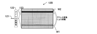
- FIG. 12 shows an example of processing by address conversion.
- FIG. 12 it is assumed that there is no error in the word W1 which is in an error state when there is no address conversion and in a state where the address conversion is present. Then, it is assumed that the error location is moved to the address position of the word W2 by address conversion.
- FIG. 12 when the failure location moves on the result storage RAM 12B depending on the presence / absence of address conversion, it can be seen that there is a failure in the data itself written in the result storage RAM 12B. That is, in the example of FIG. 12, it can be seen that there was a failure on the test object RAM 12A side.
- the data in the result storage RA12B when there is no address conversion becomes the test result of the test object RAM.
- the arrangement of data in the result storage RA12B when there is no address conversion is an example of the first data arrangement.
- the data arrangement of the result storage RA 12B when the address conversion is present is an example of the second data arrangement.
- FIG. 13 shows a processing example when the result storage RAM 12B has a failure.
- the position of the word line failure is fixed to the word W1 regardless of the presence or absence of address conversion. Even in the case of address conversion, if the position of the word line failure does not change from the state of no address conversion, it can be seen that there is a failure on the result storage RAM 12B side.
- test result in the test target RAM 12A at the failure address that cannot be normally acquired due to the failure of the result storage RAM 12B before the address conversion is stored in the address position after the address conversion. If there is a low possibility that a plurality of address line failures will occur at the same time, it is possible that there is no failure at the address position after address conversion.
- test results in the test object RAM 12A are obtained by combining with the result before conversion.
- the test result of the address causing an error in the test result without address conversion corresponds to a failure of the result storage RAM 12B and is not correct. Therefore, it is only necessary to extract, from the test result with conversion, a result in which an address in which a failure is detected before address conversion (hereinafter referred to as a failure address) is stored in the converted address. Then, by replacing the extracted test result with the result of the failure address of the test result without conversion, all the correct results can be obtained for the test target RAM 12A.
- a failure address an address in which a failure is detected before address conversion
- bit conversion when bit conversion is performed in the case of a bit line failure, bit replacement occurs in each word. Since the replacement of bits within each word results in a change in data value, it is called data conversion. Then, before and after data conversion, a conversion that does not convert the failed bit to the same bit position as before conversion may be used. If it is considered that there is a low probability that a plurality of bit positions will fail at the same time, a failure can be avoided because the bit at the failure location is likely to be converted to a location that has not failed after the conversion.
- FIG. 14 shows a processing example for avoiding a bit line failure due to data conversion.
- a data converter 124 is added to the bit line of the result storage RAM 12B.
- the data converter 124 exchanges data between bit lines to which write data is transmitted.
- bit B1 and bit B2 are interchanged.
- the data conversion unit 124 is an example of a conversion unit.
- the LSI tester 2 can determine that there is no failure in the result storage RAM 12B. Further, the LSI tester 2 can determine that a bit line failure has occurred in the bit position of the test object RAM 12A before data conversion.
- the LSI tester 2 can determine that there is a failure in the result storage RAM 12B if the bit line failure state does not change regardless of the presence or absence of data conversion, that is, if the failure bit position does not change. Further, the LSI tester 2 acquires the data of the destination bit moved by data conversion from the failure bit position on the result storage RAM 12B, and replaces it with the data at the bit position before the data conversion in the test target RAM 12A, so that the test target All test data in the RAM 12A can be acquired.
- the arrangement of data in the result storage RAM 12B when there is no data conversion is an example of the first data arrangement.
- the data arrangement in the result storage RAM 12B when data conversion is present is an example of the second data arrangement.
- the result storage RAM 12B is dedicated by combining the RAM device serving as the test target RAM 12A and the RAM device serving as the result storage RAM 12B.
- the reliability of the RAM can be ensured and the RAM test can be executed at an actual speed without providing a RAM device or a useless RAM device such as a spare area. That is, between the test object RAM 12A and the result storage RAM 12B, reading and writing of data are performed at the normal operating frequency of the LSI 1, and the reading of the result storing RAM 12B may be performed at an operating frequency suitable for the LSI tester 2. With such a configuration, a test at an actual operating frequency and a test result in a state where errors are reduced can be obtained.
- an address conversion unit 122 and a data conversion unit 124 may be provided in at least one RAM device included in the RAM 12 to form the result storage RAM 12B. Then, a RAM device having the same capacity as the result storage RAM 12B provided with the address conversion unit 122 and the data conversion unit 124 may be selected as the test target RAM 12A, and the test at the actual speed may be executed.
- the LSI tester 2 executes the tester program 21, and the failure occurs in either the test object RAM 12A or the result storage RAM 12B according to the procedure shown in FIGS. What is necessary is just to identify. Further, when a bit line failure occurs, the LSI tester 2 executes the tester program 21 and specifies whether the failure has occurred in the test object RAM 12A or the result storage RAM 12B by the procedure shown in FIG. do it.
- the RAM 12 when the number of RAM devices to be the test target RAM 12A is larger than the number of RAM devices to be the result storage RAM 12B, the RAM devices to be the test target RAM 12A are sequentially replaced and the test is executed. Good.
- FIG. 15 shows an example of a RAM test method using a BIST with a comparator.
- FIG. 15 shows the LSI 1B except that the test object RAM 12A, the result storage RAM 12B, the address conversion unit 122, the bit conversion unit 124, and the PLL (Phase Locked Loop) 16 are clearly shown. It is the same as LSI1. Therefore, in the following second embodiment, the same components as those in the first embodiment are denoted by the same reference numerals, and the description thereof is omitted.
- a test object RAM 12A and a result storage RAM 12B are illustrated.
- the LSI 1B has a plurality of RAM devices.
- the test object RAM 12A and the result storage RAM 12B are each one of the RAM devices in the LSI 1B.
- the test object RAM 12A and the result storage RAM 12B have the same capacity.
- the test target RAM 12A may be sequentially changed to execute the test. Further, when there are a plurality of RAM devices serving as the result storage RAM 12B, any one RAM device may be used as the result storage RAM 12B. Further, the test may be executed by sequentially changing the RAM device serving as the result storage RAM 12B.
- the LSI tester 2 writes test data 22 to the LSI 1B according to the tester program 21.
- the LSI tester 2 reads the value of the internal register such as the result register 15 from the LSI 1B. Then, the LSI tester 2 compares the read value from the result register 15 and the like with the test data 22. Note that the LSI tester 2 may write the test data 22 and the like to the LSI 1B and read from the result register 15 and the like of the LSI 1B at a lower speed than the actual speed during the normal operation of the LSI 1B.
- the test control circuit 11 supplies the control signal related to the test and the test data 22 written from the tester 2 to the RAM 10 with BIST to be tested.
- the operation of the test control circuit 11 is determined by the set value written from the LSI tester 2.
- the test object RAM 12A performs a test operation based on the control signal from the test control circuit 11 and the test data 22.
- the test operation is performed at an actual speed during normal operation of the LSI 1B, for example, at a clock speed by the PLL 16.
- the actual speed clock is supplied from, for example, the PLL 16.
- the result storage RAM 12B, the address conversion unit 122, and the bit conversion unit 124 transfer the data of the test target RAM 12A to the result storage RAM 12B according to the control signal from the test control circuit 11.
- the transfer is performed at an actual speed during normal operation of the LSI 1B, for example, a clock speed by the PLL 16. Whether the address conversion unit 122 and the bit conversion unit 124 perform the conversion operation is controlled by a control signal from the test control circuit 11.
- the comparator 14 compares the read value of the result storage RAM 12B with the expected value of the register 13, and stores the comparison result in the result register 15.
- the operation of the comparator 14 may be performed at a speed lower than the actual speed of the normal operation of the LSI 1B, that is, the clock speed by the PLL 16.
- an FBM is created for the purpose of failure analysis of the test target RAM 12A.
- the failure of the result storage RAM 12B is avoided by the address conversion unit 122 and the data conversion unit 124. Note that even if one or both of the test object RAM 12A and the result storage RAM 12B are not defective, the procedure described below can be carried out without any problem.
- the address conversion unit 122 performs address conversion by inverting the bit pattern of the address.
- the processing of the address conversion unit 122 is not limited to address inversion.
- the data conversion unit 124 performs data conversion by exchanging data of each word in units of 2 bits.
- the processing of the data conversion unit 122 is not limited to replacement in units of 2 bits.
- the capacity of the RAM device included in the RAM in the LSI 1B is assumed to be, for example, an address of 1024 and a bit width of 32 bits. Therefore, for example, it is assumed that both the test object RAM 12A and the result storage RAM 12B shown in FIG. 15 have an address of 1024 and a bit width of 32 bits.
- the processing of the following second embodiment is not limited to the capacity of the RAM device, the number of addresses (number of words), the bit width, and the like.
- FIG. 16 is an example of a result storage RAM 12B including an address conversion unit 122 and a data conversion unit 124.
- the LSI 1B includes an address bus 121, an address conversion unit 122 that converts address data on the address bus, an address decoder 123 that decodes data on the address bus, and a data conversion unit 124 that converts write data. And have.
- the address conversion unit 122 performs address conversion by bit-inverting the address data.
- the data conversion unit 124 converts write data by executing replacement in units of 2 bits.
- FIG. 17 illustrates the configuration of the address conversion unit 122.
- the address conversion unit 122 inverts each address signal of the address bus 121 by exclusive OR (Exclusive OR).
- exclusive OR Exclusive OR
- a gate that performs exclusive OR is called an EXOR gate.
- each EXOR gate inverts each address signal of the address bus 121 when the inversion control signal is 1.
- each EXOR gate does not invert each address signal of the address bus 121 when the inversion control signal is 0.
- the test control circuit 11 has a control terminal for controlling the inversion control signal of the address conversion unit 122 in FIG. 17 to 1 or 0.
- the test control circuit 11 has an inversion control register that holds an instruction to switch the inversion control signal of the address conversion unit 122 in FIG. 17 to 1 or 0.
- the value of the inversion control register is the test data from the LSI tester 2. 22 is set.
- FIG. 18 illustrates the configuration of the data conversion unit 124.
- the data converter 124 performs bit inversion between bit 0 and bit 1, bit 2 and bit 3, and bit 2k and bit 2k + 1 of each word.
- k is an integer of 0 or more, and the maximum value of 2k + 1 indicates the most significant bit.
- selectors SL0 to SL31 are provided for bits 0 to 31.
- the bit data input to these selectors SL0 to SL31 are indicated by IBIT0 to IBIT31.
- the bit data output from the selectors SL0 to SL31 are indicated by OBIT0 to OBIT31. Note that the output terminals of the selectors SL0 to SL31 are also identified by the symbols OBIT0 to OBIT31.
- bit 0 and bit 1 are input to the two selectors SL0 and SL1, respectively.
- the selector SL0 has an input terminal labeled 0 and an input terminal labeled 1.
- the input terminal labeled 0 of the selector SL0 is connected to the output terminal OBIT0.
- the input terminal labeled 1 of the selector SL0 is connected to the output terminal OBIT0. Therefore, the selector SL0 can switch the signal connected to the output terminal between IBIT0 and IBIT1 depending on whether the switching signal is 0 or 1. That is, the selector SL0 outputs IBIT0 when the switching signal is 0, and outputs IBIT1 when the switching signal is 1.
- the selector SL1 outputs IBIT0 when the switching signal is 1, and outputs IBIT1 when the switching signal is 0.
- the data conversion unit 124 replaces the bit data of each word every 2 bits in accordance with the switching signal.
- the test control circuit 11 has a control terminal for controlling the switching signal of the data conversion unit 124 in FIG. 18 to 1 or 0. Further, the test control circuit 11 includes, for example, an inversion control register that holds an instruction to switch the switching signal of the data conversion unit 124 in FIG. 18 to 1 or 0, and the value of the inversion control register is determined by the test from the LSI tester 2. Set by data 22. Next, a procedure for measuring the RAM will be described.
- the test pattern used for the LSI 1B test has the following configuration.
- the test pattern refers to data written to the test target RAM 12A.
- the test data 22 shown in FIG. 15 includes control data for generating a test pattern or data obtained by compressing a test pattern.
- the test data 22 includes control data for generating an expected value when the test pattern is read from the test target RAM 12A at the actual speed, or data obtained by compressing the expected value.
- Pattern 0 is data in which one word (32 bits in the first embodiment) is all zero.
- Pattern 1 is data in which one word is all ones.
- the test procedure using the test pattern is as follows. (1) The test control circuit 11 writes the pattern 0 to all addresses (0 to 1023) of the test object RAM 12A at the actual speed. (2) The test control circuit 11 reads the data in the test object RAM 12A at the actual speed and copies it to the result storage RAM 12B without performing address conversion and data conversion. That is, the test control circuit 11 reads the data of all addresses in the test target RAM 12A from the test target RAM 12A at the actual speed, and transfers the data to the same result storage RAM 12B address as the test target RAM 12A. (3) The test control circuit 11 reads data from the test result storage RAM 12B. In this case, the reading speed may not be the actual speed.
- the test control circuit 11 compares the read value by the comparator 14 with the pattern 0 as an expected value. Then, the test control circuit 11 stores, in the result register 15, a location that does not match as a result of the comparison as a failure location.
- the result register 15 may store the address where the error is detected and the comparison result of the comparator 14.
- the LSI tester 2 acquires the test result from the result register 15. Then, the LSI tester 2 may create an FBM based on the address where the error is detected and the comparison result of the comparator 14.
- the test control circuit 11 also performs a test using the pattern 1 in the same procedure as (1) to (3), and stores the failure location in the result register 15. (5)
- the failure location of pattern 0 and pattern 1 is combined to be the failure location of the RAM.
- the LSI tester 2 obtains the test result of the RAM mounted on the LSI 1B. Note that, depending on the state of the failure location, the LSI tester 2 has a “word line failure” in the case of consecutive failures in the word direction of the same address, and a “bit line failure” in the case of consecutive failures in the direction across multiple words at the same bit position. When a failure occurs at a specific address and a specific bit, the failure is classified as “single cell failure”.
- FIG. 19 shows an example of a RAM failure.
- the location of the word line failure in the test object RAM 12A is represented by “*”
- the location of the single cell failure in the result storage RAM is represented by “X”.
- test control circuit 11 performs address conversion by the address inverting unit 122 of the result storage RAM 12B, and transfers the read result from the test target RAM 12A to the result storage RAM 12B.
- FIG. 21 shows an example of the result stored in the result storage RAM 12B when the address is inverted by the address conversion unit 122.
- the test result obtained by removing the failure “ ⁇ ” of the result storage RAM 12B from the test result obtained from the result storage RAM 12B of FIG. 20 becomes the test result of the test target RAM 12A.
- FIG. 22 shows an example of a bit failure.
- FIG. 23 illustrates the result of reading the test pattern write result to the test target RAM 12A and transferring it to the result storage RAM 12B.
- data in which a failure in the test target RAM 12A and a failure in the result storage RAM 12B are mixed is obtained.
- FIG. 24 exemplifies the result of performing the transfer in units of 2 bits by the data conversion unit 124 and transferring it.
- the LSI tester 2 can determine that the failure at the location indicated by “x” that did not move is a failure inherent in the result storage RAM 12B. Therefore, the LSI tester 2 can obtain the test result of the test target RAM 12A obtained by removing the failure of the result storage RAM 12B (the location indicated by “x” in FIG. 24) from the result of FIG.
- failure having a spread in the vertical and horizontal directions of the memory cell is, for example, a case where at least one of a plurality of word line failures and a plurality of bit line failures occurs. In such a case, the failure of the test target RAM 12A and the failure of the result storage RAM 12B may not be distinguished.
- the low-speed FBM is not read from the test target RAM 12A by an actual speed clock signal such as the PLL 16, but from the LSI tester 2 to the internal register of the LSI 1B, for example, from the test target RAM 12A via the result register 15. This refers to creation of an FBM by reading.
- FIG. 25 illustrates a test processing flow by the LSI tester 2 and the test control circuit 11.
- the processing in FIG. 25 starts when the LSI tester 2 writes the test data 22 to the LSI 1B and starts the test.
- S1 to S6 are processes of the test control circuit 11
- S7 to S16 are processes of the LSI tester 2.
- the test control circuit 11 writes the test pattern 0 in the test target RAM 12A (S1).
- the test control circuit 11 reads the stored data from the test target RAM 12A. Then, the test control circuit 11 stores the read data in the result storage RAM 12B without address conversion and without data conversion (S2). Then, the test control circuit 11 reads the contents of the result storage RAM. Then, the test control circuit 11 determines whether or not the pattern 0 is read (S3). In this case, the test control circuit 11 holds the pattern 0 as an expected value in the register 13. Then, the test control circuit 11 compares the content read from the result storage RAM with the expected value by the comparator 14. The comparison result is delivered to the LSI tester 2 through the result register.
- test control circuit 11 writes the test pattern 1 in the test target RAM 12A (S4).
- test control circuit 11 reads the stored data from the test target RAM 12A.
- the test control circuit 11 stores the read data in the result storage RAM 12B without address conversion and without data conversion (S5).
- the test control circuit 11 reads the contents of the result storage RAM.
- the test control circuit 11 determines whether or not the pattern 1 has been read (S6).
- the determination procedure of S6 is the same as that of S3.
- the comparison result is delivered to the LSI tester 2 through the result register.
- the LSI tester 2 determines the RAM test result by combining the results of the pattern 0 and the pattern 1 (S7).
- the LSI tester 2 determines the presence or absence of a word line failure, for example, by determining whether or not a plurality of errors have occurred in the word direction of the same address. Further, the LSI tester 2 determines whether or not there is a bit line failure, for example, by determining whether or not an error has occurred across a plurality of words at the same bit position. Alternatively, the LSI tester 2 determines whether or not a word line failure and a bit line failure occur together and a part or all of the RAM area has a failure within a range.
- the LSI tester 2 advances the control to S9.
- the determination in S8 is Yes when only the word line failure occurs and there is no bit line failure. That is, when a word line failure and a bit line failure coexist, the failure is further determined in S14 and handled in other processing (S16).
- the LSI tester 2 sets the test data 22 so that the process of S1-S6 is executed again for pattern 0 and pattern 1, with address conversion being stored in the result storage RAM 12B.
- the test by the test control circuit 11 is started (S9).
- the LSI tester 2 determines the status of the measurement result (S10). That is, the LSI tester 2 determines whether or not the address of the word line failure has changed as a result of storing the data read from the test object RAM in the result storage RAM 12B with address conversion.
- the LSI tester 2 determines that there is a failure inherent in the result storage RAM 12B (S11). Therefore, it is determined that the word line failure specified in S7 and S8 is not a failure of the test target RAM 12A.
- the LSI tester 2 determines that the data transferred from the test target RAM 12A has an error. Therefore, the LSI tester 2 determines that there is a failure in the test target RAM 12A. These are determined by both pattern 0 and pattern 1.
- the LSI tester 2 combines the results of S11 and S12 to obtain the measurement result of the test object RAM (S13).
- the failure location of the result storage RAM 12B can be specified from the results of S11 and S12. That is, if the position of the word line failure does not move as a result of S10, the failure word or the failure bit portion at the address of the word line that has not moved can be determined as the failure position of the result storage RAM 12B.
- the LSI tester 2 determines whether there is a bit line failure (S14).
- the determination in S14 if there is no word line failure and only a bit line failure has occurred, the determination in S14 is Yes. That is, when a word line failure and a bit line failure coexist, the failure is handled in another process (S16).
- the bit line failure includes a single bit failure. That is, the LSI tester 2 handles a failure of one bit at one address as a bit line failure.
- the LSI tester 2 sets the test data 22 so that data conversion is performed when stored in the result storage RAM 12B, and the processing of S1-S6 is executed again for pattern 0 and pattern 1, A test by the test control circuit 11 is started (S15).
- the LSI tester 2 determines the status of the measurement result. That is, the LSI tester 2 determines whether the bit position of the bit line failure has changed as a result of storing the data read from the test target RAM 12A in the result storage RAM 12B with data conversion. If the bit position of the bit line failure does not move as a result of the determination, the LSI tester 2 determines that there is a failure inherent in the result storage RAM 12B.
- the LSI tester 2 determines that there is an error in the data transferred from the test target RAM 12A. Therefore, the LSI tester 2 determines that there is a failure in the test target RAM 12A.
- the LSI tester 2 executes the process of S16.
- the LSI tester 2 does not start the test by the process of S1-S6, that is, reading from the test target RAM 12A at the actual speed and storing in the result storage RAM 12B at the actual speed.
- the LSI tester 2 tests the test object RAM 12A with the low-speed FBM (S16).
- the low-speed FBM refers to a process of reading data from the test target RAM 12A and creating an FBM using the internal register of the LSB 1B.
- the LSI tester 2 uses the test control circuit 11 to read data from the test target RAM 12A and store it in the result storage RAM 12B. Start the test to be performed. Then, the LSI tester 2 determines the presence / absence of a word line error and a bit line error from the test result. If there is a word line error, the LSI tester 2 converts the data read from the test object RAM 12A by the test control circuit 11 into an address and starts a test for storing the data in the result storage RAM 12B. If the address of the error location in the result storage RAM 12B is moved due to the presence / absence of address conversion, the LSI tester 2 determines that there is an error in the test target RAM 12A.
- the LSI tester 2 converts the data read from the test target RAM 12A by the test control circuit 11 and starts a test for storing it in the result storage RAM 12B. If there is a shift in the bit position of the error location in the result storage RAM 12B due to the presence or absence of data conversion, the LSI tester 2 determines that there is an error in the test target RAM 12A.
- each of the test target RAM 12A and the result storage RAM 12B occurred without providing a dedicated spare area in the result storage RAM 12B. You can distinguish errors. If there is at least one RAM device serving as the result storage RAM 12B, the process of FIG. 25 is repeated and executed for the RAM device having the same capacity or a smaller capacity as the RAM device serving as the result storage RAM 12B. RAM device testing can be performed. That is, in order to execute the processing of FIG. 25, at least one RAM device capable of address conversion and data conversion may be provided.
- the RAM device itself used as the result storage RAM 12B is to be tested, it is sufficient to further provide one RAM device as the result storage RAM 12B.
- an address conversion and data conversion circuit may be provided in all of the RAM devices incorporated in the LSI 1.
- the LSI tester 2 has been described as executing the processing of S7 to S16.
- the RAM test method of the second embodiment is not limited to the processing described with reference to FIG.
- the test control circuit 11 may execute part or all of the processing of S7 to S16 in FIG.
- a control unit that can execute a computer program including a CPU and a main storage device may be provided in the test control circuit 11. Then, a part or all of the processing of S7 to S16 in FIG. 25 may be executed by the control unit in the test control circuit 11. In that case, the LSI tester 2 may deliver the test data 22 to the control unit in the test control circuit 11 and receive the test result.
- Example 3 shows an example of a RAM test method using BIST without a comparator.
- FIG. 26 exemplifies the procedure of the RAM test by the BIST without a comparator.
- the configuration and procedure of the third embodiment other than using the comparator-less BIST are the same as those of the second embodiment. Therefore, the same components as those of the second embodiment are denoted by the same reference numerals as those of the second embodiment, and the description thereof is omitted.
- an LSI 1C including a BIST-less RAM 10C is illustrated.
- the BIST-less RAM 10C is different from FIG. 15 in that the comparator 14 is not provided.
- the procedure of Example 3 will be described with reference to FIG.
- the LSI tester 2 writes test data 22 to the LSI 1C according to the tester program 21.
- the LSI tester 2 reads the value of the internal result register 15 from the LSI 1C and compares the read value with the test data.
- the writing / reading operation of the LSI tester 2 may be performed at a low speed instead of the LSI operating speed.
- the test control circuit 11 supplies a control signal and test data relating to the test to the circuit to be tested.
- the operation of the test control circuit 11 is determined by the set value written from the LSI tester 2.
- the test object RAM 12A performs a test operation based on the control signal and test data from the test control circuit 11.
- the test operation is performed at the LSI actual speed.
- the actual speed clock is supplied from the PLL 16.
- the result storage RAM 12B, the address conversion unit 122, and the bit conversion unit 124 transfer the contents of the test target RAM 12A to the result storage RAM 12B in response to a control signal from the test control circuit 11. The transfer is performed at the LSI actual operation speed. Whether the address conversion unit 122 and the bit conversion unit 124 perform the conversion operation is controlled by a control signal from the test control circuit 11. A control signal from the test control circuit 11 is set by test data 22 from the LSI tester 2. (5) The result register 15 stores the read value of the result storage RAM 12B according to the control signal from the test control circuit 11. The LSI tester 2 acquires a read value from the result storage RAM 12 ⁇ / b> B through the result register 15.
- the operation of reading data from the result storage RAM 12B, storing it in the result register 15, and acquiring the read value by the LSI tester 2 through the result register 15 may be performed at a low speed.
- the LSI tester 2 compares the test result read from the result storage RAM 12 ⁇ / b> B through the result register 15 with the expected value based on the test data 22. As a result, the LSI tester 2 determines the presence or absence of a word line failure for each of the test pattern 0 and the test pattern 1, and when there is a word line failure, the address of the word line failure changes depending on the presence or absence of address conversion. It is determined whether or not. Then, the LSI tester 2 determines that the test target RAM 12A is in failure when the address of the word line failure changes depending on the presence or absence of address conversion.
- the LSI tester 2 determines the presence / absence of a bit line failure for each of the test pattern 0 and the test pattern 1, and when there is a bit line failure, the bit position of the bit line failure changes depending on the presence / absence of data conversion. It is determined whether or not. Then, the LSI tester 2 determines that the test object RAM 12A is in failure when the bit position of the bit line failure changes depending on the presence or absence of data conversion.
- the test target RAM 12A and the test target RAM 12A can be provided without providing a dedicated spare area. Thus, it is possible to distinguish between errors that have occurred in the result storage RAM 12B.
- RAM addresses 0 to 1023 are divided into row numbers and column numbers to access the RAM cell array. That is, the row decoder determines an access line to the row corresponding to the row number and selects a row. The column decoder determines an access line to the column corresponding to the column number, and selects the column. In this way, the address is determined by the row number and the column number, and the bit string of the corresponding address is accessed.
- FIG. 28 illustrates the correspondence between RAM addresses, row numbers, and column numbers.
- the arrangement of RAM cells is 256 in the vertical direction and 288 in the horizontal direction, and can be arranged in a balanced manner.
- the address conversion by address inversion and the bit conversion by 2-bit unit replacement described in the first to third embodiments are applied to the RAM including the rows and columns of FIG.
- Address conversion is a means for avoiding a word line defect.
- a word line defect becomes a row defect.
- how the row number is converted by address conversion is considered.
- row 0 becomes valid when accessing RAM addresses 0 to 3, so that a failure of row 0 appears as a failure of RAM addresses 0 to 3.
- RAM addresses 0 to 3 are converted to RAM addresses 1023 to 1020.
- RAM addresses 1023 to 1020 correspond to row 255.
- row 0 is converted to row 255.
- row 1 is converted to row 254,...
- Row 255 is converted to row 0, and does not indicate the same row before and after conversion, and satisfies the address conversion condition.
- bit conversion In a RAM having a row column configuration, one bit is composed of four columns.
- address conversion by address inversion and bit conversion by 2-bit unit replacement satisfy the condition of “conversion that is not converted to the same place before and after conversion”, so that failure can be avoided.
- the bits of all addresses are inverted at the time of address conversion.
- the address translation is not limited to the configuration of the second embodiment. In short, all the addresses of the RAM device, in other words, all the words in the resultable RAM 12B have to be moved before and after the address conversion.
- FIG. 29 shows another example of address conversion in which all the words in the result possible RAM 12B move.
- the address conversion method inverts one arbitrary bit among the bits of the address.
- FIG. 29 shows a configuration example in which bit 0 is inverted. That is, an exclusive OR gate is inserted into bit 0, and the presence or absence of inversion is controlled by the inversion control signal.
- the bit to be inverted may be any one bit and is not limited to bit 0.
- address conversion by inversion of one bit does not cause the address after conversion to be the same value as before the conversion.
- address conversion can be performed with a smaller number of gates than in the second embodiment.
- the FBM can be acquired at the actual speed by writing the result of the test object RAM 12A into the result storage RAM 12B with the clock signal of the PLL 16.
- a real speed test (1) By providing the address conversion unit 122 in the test result storage RAM 12B, a word line failure in the test result storage RAM 12B is avoided.
- a bit line failure in the test result storage RAM is avoided.
- Test program 22 Test data 121 Address bus 122 Address converter 123 Address decoder 124 Data converter
Abstract
この試験方法は、試験回路により、メモリの試験対象領域に試験データを書き込み、書き込んだデータを読み出し、読み出したデータをメモリの結果格納領域に第1のデータ配置で書き込み、結果格納メモリに書き込まれたデータを読み出して、対照データと比較し、第1の比較結果を取得する。さらに、この試験方法は、メモリの試験対象領域から読み出したデータを、試験回路によりメモリの結果格納領域内で第1のデータ配置とは異なる第2のデータ配置となるように書き込み先を変換しながら、メモリの結果格納領域に再度書き込み、再度書き込んだデータを読み出して、対照データと比較し、第2の比較結果を取得する。そして、この試験方法は、第1の比較結果と第2の比較結果に応じて、メモリの不良位置を特定する。
Description
本発明は、半導体集積回路の試験に関するものである。
今日、半導体集積回路としては、RAM(Random Access Memory)を搭載したものが多数提供されている。以下、半導体集積回路をLSI(Large Scale Integration)という。RAMを搭載したLSI単体試験では、RAMの試験のために内蔵型自己診断回路が多く使用されている。内蔵型自己診断回路は、BIST(Built In Self Test)回路、あるいは試験制御回路と呼ばれる。
図1に、試験制御回路を有するLSIの構成を例示する。図1の構成では、試験制御回路は、例えば、図示しないLSIテスタからの設定にしたがい、書き込むデータと、データの書き込み先となるアドレスを発生させ、RAMにデータを書き込む。次に、試験制御回路は、RAMから書き込んだデータを読み出しデータとして読み出す。さらに、試験制御回路は、RAMに書き込んだデータを読み出したときに得られる期待値を発生させる。そして、試験制御回路は、読み出しデータと期待値とを比較器で比較することでテスト結果を生成する。図1では、テスト結果はエラー情報とされている。そして、試験制御回路は、例えば、LSIテスタの設定に応じて、読み出し回路の制御信号にしたがい、エラー情報を出力する。LSI外部の図示しないLSIテスタは、以上の手順で生成されるエラー情報をLSIから読み出す。そして、LSIテスタは、LSI内の試験制御回路から読み出したエラー情報によりRAMの良否判定を行う。
LSI内に試験制御回路を設けない従来の試験技術では、LSI外部からすべてのテストパタンをLSIに入力し、例えば、入力されたテストパタンのRAMへの格納結果を読み出していた。したがって、上記のような試験制御回路を含むLSIの試験では、従来の試験技術に比べて、大幅に試験時間および入力するテストパタン数が縮小できる。
ところで、LSIの量産では良品と不良品の判定ができれば充分である。このため、通常の試験制御回路は、RAMの良否を判定するための情報を取得する。RAMの良否を判定するための情報は、例えば、最小の情報量では、良品と不良品とを区別する情報となる。このような最小の情報量では、故障の詳細状況を得ることができない。
一方、故障解析は、故障原因を突き止めるために行われる。そのため、故障解析では、RAM内の故障しているアドレス、ビットの個数、あるいは分布状況等を示す情報が求められる。そこで、故障解析のために、RAMの故障ビット情報(フェイル・ビット・マップ:以下FBMという)を取得する手法が用いられる。
一般に、FBMを取得するにはRAMの全アドレスの全BITの情報が必要である。しかし、RAMの全アドレスの全BITの情報は膨大な情報量となる。全アドレスの全BITの情報をレジスタに格納すると仮定すると、大容量のリソースを用意することになる。そこでレジスタ量削減のために1アドレス分のレジスタを用意し、アドレスを1つ試験する度に1アドレス分の結果を読み出す手法がとられる。
図2に、1アドレス分の結果を読み出す試験制御回路の構成を例示する。図2の構成の場合、アドレスが1つ進む度に読み出し動作が行われるので動作スピードが遅くなり、実速度での測定を行うことができないという問題がある。実速度とは、例えば、LSIの通常動作時のRAMへのアクセス速度ということもできる。このアクセス速度は、例えば、LSI内のRAMアクセスに用いられるクロック周波数で定められる。
実速度での測定を行うため、RAMから読み出したデータを格納するレジスタの代わりにLSIに内蔵されているRAMを用いる方法が提案されている。この方法では、試験制御回路は、試験対象RAMの試験結果を別のRAMに実速度で格納する。図3に、試験対象RAMの試験結果を別のRAMに格納するLSIの構成を例示する。図3の構成では、試験対象RAMからデータが実速度で読み出される。読み出されたデータは、比較器で期待値と比較され、比較結果が結果格納RAMに書き込まれる。
しかし、結果格納RAMを用いる場合には、結果格納RAMに故障があると、試験対象RAMの試験ができないという問題がある。そこで、結果格納RAMに予備領域を設ける構成が提案されている。図4に、結果格納RAMに予備領域を設けたLSIの構成を例示する。結果格納RAMに予備領域を設けることにより、結果格納RAMに故障がある場合でも、試験結果を正しく保持することができる。
上述のように、実速度でFBMを取得するために試験結果を内蔵の結果格納RAMに実速度で格納する技術が提案されている。そして、試験結果格納RAMの故障に対応するために予備領域を設けることが提案されている。
しかしながら、LSIに搭載したRAMの試験のための予備領域は、専用の領域、あるいは、無駄なRAMの領域の増加となる。
そこで、開示技術の目的は、LSIに搭載されたRAMの試験ために、無駄なRAM領域を設けることなく、実速度でFBMを取得することを可能にすることである。
開示の技術の1側面は、試験装置が試験回路を有する半導体集積回路に搭載されたメモリを試験する試験方法として例示できる。この試験方法は、試験回路により、メモリの試験対象領域に試験データを書き込み、書き込んだデータを読み出し、読み出したデータをメモリの結果格納領域に第1のデータ配置で書き込み、結果格納メモリに書き込まれたデータを読み出して、対照データと比較し、第1の比較結果を取得する。さらに、この試験方法は、メモリの試験対象領域から読み出したデータを、試験回路によりメモリの結果格納領域内で第1のデータ配置とは異なる第2のデータ配置となるように書き込み先を変換しながら、メモリの結果格納領域に再度書き込み、再度書き込んだデータを読み出して、対照データと比較し、第2の比較結果を取得する。そして、この試験方法は、第1の比較結果と第2の比較結果に応じて、メモリの不良位置を特定する。
上記試験方法によれば、LSIに搭載されたRAMの試験ために、無駄なRAM領域を設けることなく、実速度でFBMを取得することができる。
以下、図面を参照して、技術の一側面として、実施の形態(以下、実施形態という)に係る半導体集積回路と、半導体集積回路の試験方法について説明する。以下の実施形態の構成は例示であり、本半導体集積回路、および本試験方法は実施形態の構成には限定されない。
以下、図5から図14の図面を参照し、実施例1に係る半導体集積回路の試験装置について説明する。図5、図6に実施例1に係るLSI試験方法で用いられる装置の構成を例示する。
<LSIとLSIテスタの構成>
LSIの試験、あるいは特性の測定等のため、LSIテスタと呼ばれる測定装置が用いられる。LSIテスタを用いて試験、測定等を行う様に設計されたLSIはLSIテスタによる値の設定と値の読出しを行うインターフェースを有している。図5および図6では、LSIテスタとLSIとのインターフェースは、二点鎖線で示されている。LSIテスタはこのインターフェースを用い、試験に必要な情報をLSI内部に設定し、試験終了後に試験結果を読み出すことができる。
LSIの試験、あるいは特性の測定等のため、LSIテスタと呼ばれる測定装置が用いられる。LSIテスタを用いて試験、測定等を行う様に設計されたLSIはLSIテスタによる値の設定と値の読出しを行うインターフェースを有している。図5および図6では、LSIテスタとLSIとのインターフェースは、二点鎖線で示されている。LSIテスタはこのインターフェースを用い、試験に必要な情報をLSI内部に設定し、試験終了後に試験結果を読み出すことができる。
図5に比較器付BISTによるRAM試験方法の例を示す。通常、LSIテスタからは電源やクロック等、試験に必要な他の信号も供給されることが多い。ただし、図5では、電源やクロック等は省略されている。図5では、試験対象のLSI1と、LSIテスタ2とが例示されている。LSI1は、BIST付RAM10と、試験結果を格納する結果レジスタ15とを有する。また、BIST付RAM10は、試験制御回路11と、RAM12と、期待値を格納するレジスタ13と、比較器14とを有する。試験制御回路11が試験回路の一例である。RAM12がメモリの一例である。期待値が対照データの一例である。
ここで、試験対象のRAM12は、通常は、複数のRAMデバイスを含む。ただし、図5では、複数のRAMデバイスを含むメモリをRAM12としている。以下の実施例では、RAM12に含まれる複数のRAMデバイスのうち、所定個数(例えば、1個)を試験対象RAMとする。試験対象RAMが試験対象領域の一例である。また、RAM12に含まれる複数のRAMデバイスのうち、試験対象RAMと同一容量の他のRAMデバイスを結果格納RAMとする。結果格納RAMが結果格納領域の一例である。したがって、図5の構成では、試験対象RAM、および結果格納RAMがRAM12に含まれる。RAMデバイスがメモリデバイスの一例である。
一方、LSIテスタ2は、図示しないCPUと主記憶装置とを有している。LSIテスタ2は、主記憶装置上に実行可能に展開されたテスタプログラム21により、LSI1等の試験、特性の測定等を実行する。また、LSIテスタ2は、主記憶装置上に試験データ22を有している。ただし、試験データ22は、ハードディスク装置、SSD(Solid State Drive)等の補助記憶装置上に保持してもよい。さらに、LSIテスタ2は、試験制御回路11および結果レジスタ15等、LSI1内の回路とのインターフェースを有している。
LSIテスタ2は、テスタプログラムを実行することにより、このインターフェースを通じて、設定値供給機能24を提供する。すなわち、LSIテスタ2の設定値提供機能24は、試験データ22から設定値を取得し、試験制御回路11に供給する。また、LSIテスタ2は、テスタプログラムを実行することにより、このインターフェースを通じて、読み出し値比較機能23を提供する。LSIテスタ2の読み出し値比較機能23は、LSI1の結果レジスタ15から試験結果、測定結果等を読み出す。
以下、LSI1の試験実行手順の例を説明する。
(1)LSIテスタ2はテスタプログラム21にしたがい、例えば、主記憶装置あるいは補助記憶装置等に内蔵した試験データ22を試験制御回路11へ設定する。試験データ22には、試験対象のRAM12に書き込むデータを発生するためのデータ、試験対象のRAM12の書き込みアドレスを発生するためのデータ、および、試験対象のRAM12から読み出されるデータの期待値を発生させるためのデータ等が含まれる。
(2)試験制御回路11は、設定された試験データにより試験を実行する。ここでは、LSI1内のRAM12に含まれる一のRAMデバイスを試験対象RAMとし、LSI1内のRAM12に含まれる他のRAMデバイスを結果格納RAMとする。試験制御回路11は、試験対象RAMからデータを実速度で読み出し、結果格納RAMに格納する。
(3)試験制御回路11は、試験結果をRAM12の結果格納RAMから読出し、比較器14により、試験データ22の期待値と比較する。比較器14は、比較結果を結果レジスタ15に格納する。なお、比較器14の処理、および結果レジスタ15への格納は実速度よりも遅い速度でもよい。図5のように、LSI1内に比較器14を設ける場合には、例えば良品=0/不良品=1などの最小限の結果情報が得られる。このため、LSIテスタ2が結果レジスタ15から読み出すデータ量は少ない。
図6に比較器無しBISTによるRAM試験方法の例を示す。図6のLSI1Aは、図5のLSI1と比較して、比較器14を有していない。したがって、試験結果と期待値との比較は、LSIテスタ2がテスタプログラム21にしたがって実行する。
(1)~(2)までの手順は図5の比較器付BISTによるRAM試験方法と同様であるので省略する。
(4)LSIテスタ2は、試験結果をLSI1のRAMの結果格納RAMから読み出し、テスタプログラム21にしたがい試験データ22に基づく期待値と比較する。なお、結果格納RAMからの試験結果の読み出しは実速度よりも遅い速度でもよい。
(1)~(2)までの手順は図5の比較器付BISTによるRAM試験方法と同様であるので省略する。
(4)LSIテスタ2は、試験結果をLSI1のRAMの結果格納RAMから読み出し、テスタプログラム21にしたがい試験データ22に基づく期待値と比較する。なお、結果格納RAMからの試験結果の読み出しは実速度よりも遅い速度でもよい。
LSI1Aは、比較器14を有していないため、LSI1Aから読み出されるデータはRAMビット幅分の結果になっている。したがって、比較器無しBISTによるRAM試験方法で読み出されるデータ量は、比較器付BISTによるRAM試験方法に比べて大きくなる。
比較器14を持つか持たないかは試験内容やLSIの構成に応じて適宜決定できる。以下、実施例1では、試験結果と期待値との比較は、図5の場合、図6場合のいずれかに限定される訳ではない。
<比較例>
図7に、比較例に係るRAMの試験方法を例示する。図7では、比較例に係るLSIのうち、試験制御回路311、およびRAM312が例示されている。また、RAM312は、試験対象RAM312Aおよび結果格納RAM312Bを含む。また、図7では、テスタ2は、省略されている。
図7に、比較例に係るRAMの試験方法を例示する。図7では、比較例に係るLSIのうち、試験制御回路311、およびRAM312が例示されている。また、RAM312は、試験対象RAM312Aおよび結果格納RAM312Bを含む。また、図7では、テスタ2は、省略されている。
試験制御回路311による試験の実行手順は以下の通りである。
(1)試験制御回路311から試験対象RAM312Aに試験データを実速度で書き込む。
(2)試験制御回路311により試験対象RAMのデータを実速度で読み出して結果格納RAM312Bへ書き込む。
(3)結果格納RAMのデータをLSI外部に読み出す。この動作は低速でも構わない。
(4)試験制御回路311によって書き込まれた試験データのデータは予め判っている。そこで、テスタ2は、試験制御回路311によって書き込まれた試験データと同一の値を期待値とすればよい。テスタ2は、読み出した結果格納RAM312Bのデータと期待値とを比較をする。
(5)結果格納RAM312Bのデータと期待値とが一致すれば、試験結果は正常であると判定される。
RAMの故障は0故障(0の読み書きができない)と1故障(1の読み書きができない)がある。このため、試験制御回路311は、RAM312内の各メモリセルに対し、0と1とを上記方法によりそれぞれ少なくとも1回以上書き込み、試験する。
ところで、比較例による方法では試験結果にエラーがあった場合に試験対象RAM312Aと結果格納RAM312Bのどちらの故障であるかを区別することはできない。
<RAMの故障の分類>
RAMの故障のほとんどは以下の3種類に分類される。
(1)RAMセル故障;
RAMの故障の第1の種類は、RAM内のセルが故障するケース(RAMセル故障)である。RAMセル故障は、故障箇所が1個(単セル)である場合が多い。図8に、単セル故障を例示する。図8の黒で塗りつぶしたセルが故障箇所である。図8では、1つのアドレスで指定されるワード上の1つのビットが故障している。
(2)ワード線故障;
RAMの故障の第2の種類は、RAMセルが同一アドレスのワード方向に連続して故障するケース(ワード線故障)である。ワード線故障は、RAM内のアドレスを指定する制御線の故障である。RAM内のアドレスを指定する制御線は、ワード線と呼ばれる。ワード線故障は、故障箇所が1つのワード線である場合が多い。図9に、ワード線故障を例示する。図9の黒で塗りつぶしたセルが故障箇所である。図9では、1つのアドレスで指定される1つのワードに含まれる全ビットが故障している。
(3)ビット線故障
RAMの故障の第2の種類は、RAMセルが1つのビット位置で複数のワードに渡って連続して故障するケース(ビット線故障)である。ビット線故障は、RAM内のビット位置を指定する制御線の故障である。RAM内のビット位置を指定する制御線は、ビット線と呼ばれる。ビット線故障は、故障箇所が1つのビット線である場合が多い。図10に、ビット線故障を例示する。図10の黒で塗りつぶしたセルが故障箇所である。図10では、1つのビット線で指定される1つのビット位置上の全ビットが故障している。
ワード線故障に関して、図9では1ワード線で指定される全ビット(全セル)が故障している。また、ビット線故障に関して、図10では1ビット線で指定されるビット位置の全ビット(全セル)が故障している。ただし、ワード故障において、1ワード線で指定される全セルが故障するとは限らない。また、1ビット線で指定される全セルが故障するとは限らない。例えば、まばらに故障する場合も生じ得る。単セル不良は、最小故障(故障セルが1個)のワード線故障またはビット線故障であると考えれば、ワード線故障またはビット線故障に含めて処理することも可能となる。
よって、RAM故障においてワード線故障またはビット線故障の2種類の故障に対応すれば、ほとんどの場合について、故障検知、故障解析が可能となる。
<実施例1の試験方法>
(ワード線故障の回避)
実施例1の方法では、ワード故障が1箇所である場合は、アドレス変換、すなわち、選択するワード線の変換を行う。アドレス変換前後で同一アドレスに変換されない変換を用いれば、故障箇所のアドレスが他のアドレスに変換される。したがって、複数のワード線が同時に故障しているという状態でない場合には、アドレス変換後には故障していないアドレス線に対応するアドレスに変換される可能性が高い。このため、アドレス変換によって故障箇所を回避できる。図11に、アドレス変換前のワード線故障の例を示す。図11の例では、結果格納RAM12Bのアドレスバス121とアドレスデコーダ123との間に、アドレス変換部122が設けられている。例えば、アドレスバス121は、所定のビット幅でアドレスを指定する。アドレスデコーダ123は、指定されたアドレスに対応する1つのアドレス線を選択する。アドレス変換部122が変換部の一例である。
図11は、アドレス変換部122によるアドレス変換のない状態を例示する。いま、アドレス変換部122によるアドレス変換が実行されない状態で、ワードW1に対応する全ビットが故障したと仮定する。この時点では、まだ、試験対象RAM12Aと結果格納RAM12Bのうち、どちらのRAMの故障かは、判断できない。
次にアドレス変換部122によるアドレス変換を行った状態で、図11と同様の試験を行う。図12にアドレス変換による処理例を示す。図12のようにアドレス変換無のときにエラーの状態であったワードW1が、アドレス変換有の状態ではエラーがなくなったとする。そして、アドレス変換により、ワードW2のアドレス位置にエラー箇所が移動したとする。図12のように、アドレス変換の有無によって、結果格納RAM12B上で、故障箇所が移動する場合、結果格納RAM12Bに書き込まれるデータ自体に故障があることが分かる。すなわち、図12の例では、試験対象RAM12A側に故障あったことが分かる。この場合、結果格納RAMには故障がないため、アドレス変換無のときの結果格納RA12Bのデータが試験対象RAMの試験結果となる。アドレス変換無のときの結果格納RA12Bのデータの配置が第1のデータ配置の一例である。また、アドレス変換有のときの結果格納RA12Bのデータの配置が第2のデータ配置の一例である。
図13に、結果格納RAM12Bが故障の場合の処理例を示す。図13では、アドレス変換の有無によらず、ワード線故障の位置がワードW1に固定されている。アドレス変換ありの場合においても、ワード線故障の位置がアドレス変換なしの状態から変化しない場合、結果格納RAM12B側に故障があったことが分かる。
また、アドレス変換前に結果格納RAM12Bの故障により、正常に取得できていない故障アドレスでの試験対象RAM12Aでの試験結果は、アドレス変換後のアドレス位置に格納されている。同時に複数のアドレ線故障が生じる可能性が低いとすれば、アドレス変換後のアドレス位置には、故障はないとしてよい。
したがって、変換前の結果と合わせることにより、試験対象RAM12Aでのすべての試験結果が得られる。具体的にはアドレス変換無での試験結果でエラーを起こしているアドレスの試験結果は、結果格納RAM12Bの故障に該当し、正しくない。そこで、変換有の試験結果から、アドレス変換前に故障が検知されたアドレス(以下、故障アドレス)が変換されたアドレスに格納されている結果を抜き出せばよい。そして、抜き出した試験結果を変換無の試験結果の故障アドレスの結果と入れ替えることにより、試験対象RAM12Aについて、すべてが正しい結果が得られる。
(ビット線故障の回避)
ビット線故障が1箇所である場合は、ビット線の変換を行うことにより、ワード線故障の場合と同様に処理できる。ただし、ワード線の変換の場合には、ワード位置を入れ替えた。すなわち、変換前に故障していたワード位置と、他のワード位置とで、データが入れ替わるように全ワードデータにアドレス変換を実行した。
(ビット線故障の回避)
ビット線故障が1箇所である場合は、ビット線の変換を行うことにより、ワード線故障の場合と同様に処理できる。ただし、ワード線の変換の場合には、ワード位置を入れ替えた。すなわち、変換前に故障していたワード位置と、他のワード位置とで、データが入れ替わるように全ワードデータにアドレス変換を実行した。
一方、ビット線故障の場合に、ビットの変換を行うと、各ワード内で、ビットの入れ替えが生じる。各ワード内でのビットの入れ替えは、データ値の変更となるので、データ変換と呼ぶ。そして、データ変換前後で、故障ビットが変換前と同じビット位置に変換されないような変換を用いればよい。同時に複数のビット位置が故障する状態になる確率が低いと考えれば、故障箇所のビットは変換後に故障していない場所に変換される可能性が高いため故障を回避できる。
図14に、データ変換によるビット線故障を回避する処理例を示す。図14の例では、結果格納RAM12Bのビット線にデータ変換部124が付加されている。データ変換部124は、書き込みデータが伝送されるビット線相互の間で、データを入れ替える。例えば、ビットB1とビットB2とが入れ替えられる。データ変換部124が変換部の一例である。
データ変換の有無によって、ビット線故障の状態が変化した場合、すなわち、故障ビット位置が変化した場合には、LSIテスタ2は、結果格納RAM12Bには、故障がないと判断できる。また、LSIテスタ2は、試験対象RAM12Aのデータ変換前のビット位置にビット線故障があったと判定できる。
一方、データ変換の有無によらず、ビット線故障の状態が変化しない場合、すなわち、故障ビット位置が変化しない場合には、LSIテスタ2は、結果格納RAM12Bに、故障があると判断できる。また、LSIテスタ2は、結果格納RAM12B上の故障ビット位置からデータ変換によって移動した移動先のビットのデータを取得し、試験対象RAM12Aのデータ変換前のビット位置のデータと置き換えることで、試験対象RAM12Aの全試験データを取得できる。データ変換の無のときの結果格納RAM12Bのデータの配置が第1のデータ配置の一例である。また、データ変換の有のときの結果格納RAM12Bのデータの配置が第2のデータ配置の一例である。
以上述べたように、実施例1のLSI1によれば、LSI1に搭載されたRAM12のうち、試験対象RAM12AとなるRAMデバイスと結果格納RAM12BとなるRAMデバイスとを組み合わせることによって、結果格納RAM12Bとして専用のRAMデバイス、あるいは、予備領域のような無駄なRAMデバイスを設けることなく、信頼性を確保して、実速度でのRAMの試験を実行できる。すなわち、試験対象RAM12Aと結果格納RAM12Bとの間では、データの読み出しと書き込みとを通常のLSI1の動作周波数で行い、結果格納RAM12Bの読み出しは、LSIテスタ2に適した動作周波数で行えばよい。このような構成により、実際の動作周波数での試験と、誤りを低減した状態での試験結果の取得が可能となる。
その場合に、例えば、RAM12に含まれる、少なくとも1つのRAMデバイスに、アドレス変換部122と、データ変換部124とを設け、結果格納RAM12Bとすればよい。そして、アドレス変換部122と、データ変換部124とを設けた結果格納RAM12Bと同一容量のRAMデバイスを試験対象RAM12Aとして選択し、実速度での試験を実行すればよい。そして、ワード線故障が発生した場合には、LSIテスタ2がテスタプログラム21を実行し、図11-図13に示した手順で、試験対象RAM12Aと結果格納RAM12Bのいずれにおいて、故障が発生しているかを特定すればよい。また、ビット線故障が発生した場合には、LSIテスタ2がテスタプログラム21を実行し、図14に示した手順で、試験対象RAM12Aと結果格納RAM12Bのいずれにおいて、故障が発生しているかを特定すればよい。
さらに、RAM12中で、試験対象RAM12AとなるRAMデバイスの数が、結果格納RAM12BとなるRAMデバイスの数よりも多い場合には、順次、試験対象RAM12AとなるRAMデバイスを入れ替え、試験を実行すればよい。
以下、図15から図25の図面を参照し、実施例2に係る半導体集積回路の試験装置について説明する。
<LSIおよびLSIテスタの構成>
図15に、比較器付BISTによるRAM試験方法の例を示す。図15は、LSI1Bにおいて、試験対象RAM12Aと、結果格納RAM12Bと、アドレス変換部122と、ビット変換部124と、PLL(Phase Locked Loop)16とが明示されている点を除いて、図5のLSI1と同様である。そこで、以下の実施例2において、実施例1と同一の構成要素については、同一の符号を付してその説明を省略する。
図15に、比較器付BISTによるRAM試験方法の例を示す。図15は、LSI1Bにおいて、試験対象RAM12Aと、結果格納RAM12Bと、アドレス変換部122と、ビット変換部124と、PLL(Phase Locked Loop)16とが明示されている点を除いて、図5のLSI1と同様である。そこで、以下の実施例2において、実施例1と同一の構成要素については、同一の符号を付してその説明を省略する。
なお、図15において、試験対象RAM12Aと、結果格納RAM12Bとが例示されている。実施例2においても、実施例1のLSI1と同様、LSI1Bは、複数のRAMデバイスを有している。試験対象RAM12Aおよび結果格納RAM12Bは、それぞれLSI1B内のRAMデバイスの1つである。また、基本的には、試験対象RAM12Aと結果格納RAM12Bとは、同一の容量である。ただし、LSI1B内に、複数の試験対象RAM12Aがあってもよい。また、LSI1B内に、複数の結果格納RAM12Bがあってもよい。
試験対象RAM12AとなるRAMデバイスの数が、結果格納RAM12Bよりも多い場合には、順次、試験対象RAM12Aを変更して、試験を実行すればよい。また、結果格納RAM12BとなるRAMデバイスが複数ある場合には、いずれか1つのRAMデバイスを結果格納RAM12Bとしてもよい。また、順次、結果格納RAM12BとなるRAMデバイスを変更して、試験を実行してもよい。
図15において、LSIテスタ2はテスタプログラム21にしたがい試験データ22をLSI1Bに書き込む。また、LSIテスタ2はLSI1Bから、結果レジスタ15等の内部レジスタの値を読み出す。そして、LSIテスタ2は、結果レジスタ15等から読出し値と、試験データ22との比較を行う。なお、LSIテスタ2によるLSI1Bへの試験データ22等の書き込み、LSI1Bの結果レジスタ15等からの読み出し動作は、LSI1Bの通常動作時の実速度よりも低速で行っても構わない。
試験制御回路11は試験に関する制御信号、およびテスタ2から書き込まれた試験データ22等を試験対象のBIST付RAM10に供給する。実施例2では、試験制御回路11の動作はLSIテスタ2から書き込まれる設定値によって決定される。
試験対象RAM12Aは試験制御回路11からの制御信号と試験データ22により試験動作を行う。試験動作はLSI1Bの通常動作時の実速度、例えば、PLL16によるクロック速度で行われる。実速度のクロックは、例えば、PLL16から供給される。
結果格納RAM12B、アドレス変換部122、ビット変換部124は試験制御回路11からの制御信号により、試験対象RAM12Aのデータを結果格納RAM12Bへ転送する。転送はLSI1Bの通常動作時の実速度、例えば、PLL16によるクロック速度で行われる。また、アドレス変換部122、ビット変換部124が変換動作を行うかどうかは試験制御回路11からの制御信号により制御される。
比較器14は結果格納RAM12Bの読み出し値と、レジスタ13の期待値とを比較し、比較結果を結果レジスタ15に格納する。比較器14の動作は、LSI1Bの通常動作の実速度、すなわち、PLL16によるクロック速度よりも低速で行っても構わない。
以下、実施例2では、試験対象RAM12Aの不良解析を目的にFBMを作成する。そして、実施例2でも実施例1と同様、結果格納RAM12Bの故障をアドレス変換部122とデータ変換部124とによって回避する。なお、試験対象RAM12Aおよび結果格納RAM12Bのうち、いずれかのRAM、もしくは、両方のRAMに不良がない場合でも、以下で説明する手順は問題なく実施可能である。
また、実施例2では、アドレス変換部122は、アドレスのビットパタンを反転することによりアドレス変換を実行する。ただし、アドレス変換部122の処理がアドレス反転に限定される訳ではない。同様に、データ変換部124は、各ワードのデータを2ビット単位で入れ替えることにより、データ変換を実行する。ただし、データ変換部122の処理が2ビット単位の入れ替えに限定される訳ではない。
また、LSI1B内のRAMに含まれるRAMデバイスの容量は、例えば、アドレスが1024、ビット幅が32ビットと想定する。したがって、例えば、図15に示した試験対象RAM12A、および結果格納RAM12Bともに、アドレスが1024、ビット幅が32ビットであると仮定する。ただし、以下の実施例2の処理がRAMデバイスの容量、アドレスの数(ワード数)、ビット幅等に限定される訳ではない。
図16は、アドレス変換部122とデータ変換部124とを含む結果格納RAM12Bの例である。図16のように、LSI1Bは、アドレスバス121と、アドレスバスのアドレスデータを変換するアドレス変換部122と、アドレスバスのデータをデコードするアドレスデコーダ123と、書き込みデータをデータ変換するデータ変換部124とを有する。ただし、上述のように、アドレス変換部122は、アドレスデータをビット反転することでアドレス変換を実行する。また、データ変換部124は、2ビット単位の入れ替えを実行することで、書き込みデータをデータ変換する。
図17に、アドレス変換部122の構成を例示する。アドレス変換部122は、アドレスバス121の各アドレス信号を排他論理和(Exclusive OR)によって、反転する。以下、排他論理和を実行するゲートをEXORゲートと呼ぶ。ただし、各EXORゲートは、反転制御信号が1の場合に、アドレスバス121の各アドレス信号を反転する。一方、各EXORゲートは、反転制御信号が0の場合に、アドレスバス121の各アドレス信号を反転しない。例えば、試験制御回路11は、図17のアドレス変換部122の反転制御信号を1または0に制御する制御端子を有する。また、試験制御回路11は、図17のアドレス変換部122の反転制御信号を1または0に切り替える指示を保持する反転制御レジスタを有し、反転制御レジスタの値は、LSIテスタ2からの試験データ22によって設定される。
図18に、データ変換部124の構成を例示する。データ変換部124は、例えば、各ワードのビット0とビット1との間、ビット2とビット3との間、ビット2kとビット2k+1との間でビットの反転を実行する。ここで、kは0以上の整数で、2k+1の最大値が最上位ビットを示す。図18では、ビット0からビット31までについて、セレクタSL0からSL31が設けられている。また、これらのセレクタSL0~SL31に入力されるビットデータがIBIT0~IBIT31で示されている。また、セレクタSL0~SL31から出力されるビットデータがOBIT0~OBIT31で示されている。なお、各セレクタSL0~SL31の出力端子もOBIT0~OBIT31の符号で識別することにする。
この場合、例えば、ビット0とビット1のそれぞれが、2つのセレクタSL0とSL1に入力される。セレクタSL0は、符号0を付された入力端子と、符号1を付された入力端子を有する。切替信号が0のとき、セレクタSL0の符号0を付された入力端子が、出力端子OBIT0に接続される。一方、切替信号が1のとき、セレクタSL0の符号1を付された入力端子が、出力端子OBIT0に接続される。したがって、セレクタSL0は、切替信号が0か1かに応じて、出力端子に接続する信号をIBIT0とIBIT1との間で切り替えることができる。すなわち、セレクタSL0は、切替信号が0ときに、IBIT0を出力し、切替信号が1のとき、IBIT1を出力する。一方、セレクタSL1は、切替信号が1ときに、IBIT0を出力し、切替信号が0のとき、IBIT1を出力する。以上のように、データ変換部124は、切替信号に応じて、2ビットごとに、各ワードのビットデータを入れ替える。
例えば、試験制御回路11は、図18のデータ変換部124の切替信号を1または0に制御する制御端子を有する。また、試験制御回路11は、例えば、図18のデータ変換部124の切替信号を1または0に切り替える指示を保持する反転制御レジスタを有し、反転制御レジスタの値は、LSIテスタ2からの試験データ22によって設定される。次に、RAMを測定する手順を説明する。
<試験データの構成>
LSI1Bの試験に使用する試験パタンは以下の構成とする。ここで、試験パタンとは、試験対象RAM12Aに書き込まれるデータをいう。なお、図15に示した試験データ22は、試験パタンを発生させるための制御データ、あるいは試験パタンを圧縮したデータを含む。また、試験データ22は、試験パタンが試験対象RAM12Aから実速度で読み出されるときの期待値を発生させるための制御データ、あるいは期待値を圧縮したデータを含む。
LSI1Bの試験に使用する試験パタンは以下の構成とする。ここで、試験パタンとは、試験対象RAM12Aに書き込まれるデータをいう。なお、図15に示した試験データ22は、試験パタンを発生させるための制御データ、あるいは試験パタンを圧縮したデータを含む。また、試験データ22は、試験パタンが試験対象RAM12Aから実速度で読み出されるときの期待値を発生させるための制御データ、あるいは期待値を圧縮したデータを含む。
試験パタンとしては、パタン0とパタン1の2種類のデータが用いられる。パタン0は、1ワード(実施例1では32ビット)がすべて0のデータである。また、パタン1は、1ワードがすべて1のデータである。
<試験手順>
試験パタンによる試験手順は以下の通りである。
(1)試験制御回路11は、パタン0を試験対象RAM12Aの全アドレス(0~1023)に実速度で書き込む。
(2)試験制御回路11は、試験対象RAM12Aのデータを実速度で読み出し、アドレス変換およびデータ変換を行わずに結果格納RAM12Bにコピーする。すなわち、試験制御回路11は、試験対象RAM12Aの全アドレスのデータを実速度で試験対象RAM12Aから読み出し、試験対象RAM12Aのアドレスと同一の結果格納RAM12Bのアドレスに転送する。
(3)試験制御回路11は、試験結果格納RAM12Bのデータを読み出す。この場合の読み出し速度は、実速度でなくてもよい。また、試験制御回路11は、パタン0を期待値として、読み出した値を比較器14により比較する。そして、試験制御回路11は、比較の結果、不一致となる箇所を故障箇所として、結果レジスタ15に格納する。結果レジスタ15には、エラーが検出されたアドレスと、比較器14の比較結果を格納すればよい。LSIテスタ2は、結果レジスタ15から試験結果を取得する。そして、LSIテスタ2は、エラーが検出したアドレスと、比較器14の比較結果を基に、FBMを作成すればよい。
(4)試験制御回路11は、(1)~(3)と同様の手順で、パタン1による試験も行い、故障箇所を結果レジスタ15に格納する。
(5)パタン0とパタン1の故障箇所を合わせてRAMの故障箇所とする。
以上の手順により、LSIテスタ2は、LSI1Bに搭載されたRAMの試験結果を得る。なお、LSIテスタ2は、故障箇所の状態により、同一アドレスのワード方向に連続した故障の場合“ワード線故障”、同一ビット位置で複数ワードに渡る方向に連続した故障の場合“ビット線故障”、特定のアドレスと特定のビットで故障の場合は“単セル故障”と分類する。
図19に、RAM故障の例を示す。図19では、試験対象RAM12Aは、アドレス=1にワード線故障を持ち、結果格納RAM12Bはアドレス=3、bit=1に単セル故障を持っているとする。図中で試験対象RAM12Aのワード線故障の場所は"*"、結果格納RAMの単セル故障の場所は"X"で表している。
この状態で、試験対象RAM12Aの結果を結果格納RAM12Bに転送して結果格納RAM12Bのデータを読み出すと図20のようなデータが得られる。すなわち、試験対象RAM12Aの故障と、結果格納RAM12Bの故障とが混在した結果が得られる。したがって、結果格納RAM12Bのデータを読み出しただけでは、混在した結果を分離することができない。
そこで、次に、試験制御回路11は、結果格納RAM12Bのアドレス反転部122によるアドレス変換を行い、試験対象RAM12Aから読み出し結果を結果格納RAM12Bに転送する。
図21に、アドレス変換部122によるアドレス反転時の結果格納RAM12Bへの格納結果の例を示す。アドレス変換部122のアドレス変換により、アドレス=1のワード(上から2番目)は、アドレス=1022のワード(下から2番目)に変換される。図21の例では、アドレス変換前にワード1にあった故障データのワードがアドレス=1022のワードに移動する。このため、アドレス=1022に移動した"*"で示される箇所の故障データが試験対象RAMから転送されてきた故障と判断される。一方、アドレス=3、ビット1にあった故障データは、アドレス変換の前後で移動しない。このため、アドレス変換の前後で移動しなかった"×"で示される箇所の故障が結果格納RAM12Bに内在していた故障となる。
よって、図20の結果格納RAM12Bから得られる試験結果から、結果格納RAM12Bの故障"×"を取り除いたものが、試験対象RAM12Aの試験結果となる。
次に、ビット線故障の場合を考える。図22にビット故障の例を示す。図22では、試験対象RAM12Aは、ビット=30にビット線故障の箇所を有する。また、結果格納RAM12Bは、アドレス=3、bit=1に単セル故障を有する。
図23に、試験対象RAM12Aへの試験パタンの書き込み結果を読み出し、結果格納RAM12Bに転送した結果を例示する。図23のように、試験対象RAM12Aの故障と、結果格納RAM12Bの故障とが混在したデータが得られる。
図24に、データ変換部124により、2ビット単位での入れ替えを行い、転送した結果を例示する。ビット変換により、ビット=30(図24で右から2番目の列)はビット=31(同図で一番右の列)に変換される。図24では、故障データがビット=30からビット=31移動する。このため、LSIテスタ2は、ビット=31に移動した"*"で示される箇所の故障が試験対象RAM12Aから転送されてきた故障であると判定できる。一方、図24の故障のうち、アドレス=3、ビット=1の故障は移動しない。このため、LSIテスタ2は、移動しなかった"×"で示される箇所の故障が結果格納RAM12Bに内在していた故障であると判定できる。よって、LSIテスタ2は、図24の結果から、結果格納RAM12Bの故障(図24で"×"で示される箇所)を取り除いたものを試験対象RAM12Aの試験結果として得ることができる。
図24に、データ変換部124により、2ビット単位での入れ替えを行い、転送した結果を例示する。ビット変換により、ビット=30(図24で右から2番目の列)はビット=31(同図で一番右の列)に変換される。図24では、故障データがビット=30からビット=31移動する。このため、LSIテスタ2は、ビット=31に移動した"*"で示される箇所の故障が試験対象RAM12Aから転送されてきた故障であると判定できる。一方、図24の故障のうち、アドレス=3、ビット=1の故障は移動しない。このため、LSIテスタ2は、移動しなかった"×"で示される箇所の故障が結果格納RAM12Bに内在していた故障であると判定できる。よって、LSIテスタ2は、図24の結果から、結果格納RAM12Bの故障(図24で"×"で示される箇所)を取り除いたものを試験対象RAM12Aの試験結果として得ることができる。
ワード線故障、ビット線故障のどちらの不良でもない、メモリセルの縦横に広がりがあるような故障の場合は変換前後の領域に重なりが発生する可能性がある。メモリセルの縦横に広がりがある故障とは、例えば、複数ワード線故障および複数のビット線故障の少なくとも一方が生じた場合である。このような場合、試験対象RAM12Aの故障と結果格納RAM12Bの故障とを区別できない場合がある。
しかしながら、メモリセルの縦横に広がりを持つ様な故障の場合は、経験的に低速動作でも故障が検出されるケースが多い。そこで、メモリセルの縦横に広がりを持つ様な故障は、結果格納RAM12Bへの実速度転送を用いずに、試験対象RAM12A単独での低速FBMを実施する場合でも、充分な試験が可能である。ここで、低速FBMとは、PLL16のような実速度のクロック信号による試験対象RAM12Aからの読み出しではなく、LSIテスタ2から、LSI1Bの内部レジスタ、例えば、結果レジスタ15を介した試験対象RAM12Aからの読み出しによるFBMの作成をいう。
図25に、LSIテスタ2および試験制御回路11による試験の処理フローを例示する。図25の処理は、LSIテスタ2が試験データ22をLSI1Bに書き込み、試験を起動することで開始する。図25の各処理のうち、例えば、S1-S6が試験制御回路11の処理であり、S7-S16がLSIテスタ2の処理である。試験が起動されると、まず、試験制御回路11が試験対象RAM12Aへ試験パタン0を書き込む(S1)。
次に、試験制御回路11は、試験対象RAM12Aから、格納されているデータを読み出す。そして、試験制御回路11は、アドレス変換なし、かつ、データ変換なしで、読み出したデータを結果格納RAM12Bへ格納する(S2)。そして、試験制御回路11は、結果格納RAMの内容を読み出す。そして、試験制御回路11は、パタン0が読み出されているか否かを判定する(S3)。この場合、試験制御回路11は、パタン0を期待値としてレジスタ13に保持する。そして、試験制御回路11は、比較器14により、結果格納RAMから読み出した内容と、期待値とを比較する。比較結果は、結果レジスタを通じて、LSIテスタ2に引き渡される。
次に、試験制御回路11は、試験対象RAM12Aへ試験パタン1を書き込む(S4)。次に、試験制御回路11は、試験対象RAM12Aから、格納されているデータを読み出す。そして、試験制御回路11は、アドレス変換なし、かつ、データ変換なしで、読み出したデータを結果格納RAM12Bへ格納する(S5)。そして、試験制御回路11は、結果格納RAMの内容を読み出す。そして、試験制御回路11は、パタン1が読み出されているか否かを判定する(S6)。S6の判定手順は、S3と同様である。比較結果は、結果レジスタを通じて、LSIテスタ2に引き渡される。
次に、LSIテスタ2は、パタン0、パタン1の結果を合わせて、RAM試験結果を判定する(S7)。LSIテスタ2は、例えば、同一アドレスのワード方向に複数のエラーが発生しているか否かを判定することにより、ワード線故障の有無を判定する。また、LSIテスタ2は、例えば、同一ビット位置において、複数のワードに渡ってエラーが発生しているか否かを判定することにより、ビット線故障の有無を判定する。あるいは、LSIテスタ2は、ワード線故障およびビット線故障がまとまって発生し、RAM領域の一部あるいはすべてが面積を持つ範囲で故障しているか否か等を判定する。
そして、ワード線故障の場合には(S8の判定でYesの場合)、LSIテスタ2は、制御をS9へ進める。ただし、S8の判定は、ワード線故障のみが発生し、ビット線故障がない場合に、Yesとする。つまり、ワード線故障とビット線故障が混在する場合には、故障は、S14でさらに判定がなされ、他の処理(S16)で取り扱われる。
S8の判定でYesの場合、LSIテスタ2は、結果格納RAM12Bへ格納時にアドレス変換ありとして、パタン0とパタン1について、再度S1-S6の処理を実行するように、試験データ22を設定し、試験制御回路11による試験を起動する(S9)。そして、LSIテスタ2は、測定結果の状況を判定する(S10)。すなわち、LSIテスタ2は、試験対象RAMから読み出したデータをアドレス変換ありで結果格納RAM12Bへ格納した結果、ワード線故障のアドレスが変化したか否かを判定する。
S10の結果、ワード線故障の位置が移動しなかった場合、LSIテスタ2は、結果格納RAM12Bに内在している故障があると判定する(S11)。したがって、S7、S8で特定されたワード線故障は、試験対象RAM12Aの故障ではないと判定される。一方、S10の結果、ワード線故障の位置が移動した場合、LSIテスタ2は、試験対象RAM12Aから転送されたデータに誤りがあると判定する。したがって、LSIテスタ2は、試験対象RAM12Aに故障があると判定する。これらは、パタン0およびパタン1の両方で、判定される。次に、LSIテスタ2は、S11およびS12の結果を合わせて、試験対象RAMの測定結果とする(S13)。なお、S11とS12の結果から、結果格納RAM12Bの故障個所を特定可能である。すなわち、S10の結果、ワード線故障の位置が移動しなかった場合には、移動しなかったワード線のアドレスでの故障ワード、あるいは故障ビット部分が結果格納RAM12Bの故障位置と判定できる。
また、S8の判定で、ワード線故障がない場合、LSIテスタ2は、ビット線故障があるか否かを判定する(S14)。ここで、S14の判定では、ワード線故障がなく、ビット線故障だけが発生している場合に、S14でYesの判定となる。つまり、ワード線故障とビット線故障が混在する場合には、故障は、他の処理(S16)で取り扱われる。なお、S14の判定で、ビット線故障には、単一ビットの故障も含まれる。すなわち、LSIテスタ2は、1つのアドレスの1つビットの故障も、ビット線故障として取り扱う。
ビット線故障があった場合、LSIテスタ2は、結果格納RAM12Bへ格納時にデータ変換ありとして、パタン0とパタン1について、再度S1-S6の処理を実行するように、試験データ22を設定し、試験制御回路11による試験を起動する(S15)。
そして、LSIテスタ2は、測定結果の状況を判定する。すなわち、LSIテスタ2は、試験対象RAM12Aから読み出したデータをデータ変換ありで結果格納RAM12Bへ格納した結果、ビット線故障のビット位置が変化したか否かを判定する。判定の結果、ビット線故障のビット位置が移動しなかった場合、LSIテスタ2は、結果格納RAM12Bに内在している故障があると判定する。
一方、判定の結果、ビット線故障の位置が移動した場合、LSIテスタ2は、試験対象RAM12Aから転送されたデータに誤りがあると判定する。したがって、LSIテスタ2は、試験対象RAM12Aに故障があると判定する。
また、S14の判定で、ビット線故障でも、ワード線故障でもない場合、LSIテスタ2は、S16の処理を実行する。S16の処理では、LSIテスタ2は、S1-S6の処理、すなわち、実速度での試験対象RAM12Aからの読み出し、実速度での結果格納RAM12Bへの格納による試験を起動しない。S1-S6の代わりに、LSIテスタ2は、試験対象RAM12Aを低速FBMで試験する(S16)。低速FBMとは、例えば、図2に示したように、LSB1Bの内部レジスタを用いて、試験対象RAM12Aからデータを読み出し、FBMを作成する処理をいう。
以上述べたように、実施例2の試験制御回路11を含むLSI1Bでは、LSIテスタ2は、試験制御回路11によって実速度での試験対象RAM12Aからのデータの読み出しと、結果格納RAM12Bへの格納を行う試験を起動する。そして、LSIテスタ2は、試験結果から、ワード線エラーと、ビット線エラーの有無を判定する。そして、ワード線エラーがあった場合には、LSIテスタ2は、試験制御回路11によって試験対象RAM12Aから読み出したデータをアドレス変換して、結果格納RAM12Bへ格納する試験を起動する。そして、アドレス変換の有無で、結果格納RAM12Bでのエラー箇所のアドレスの移動があった場合には、LSIテスタ2は、試験対象RAM12Aのエラーであると判定する。
また、試験結果に、ビット線エラーがあった場合には、LSIテスタ2は、試験制御回路11によって試験対象RAM12Aから読み出したデータをデータ変換して、結果格納RAM12Bへ格納する試験を起動する。そして、データ変換の有無で、結果格納RAM12Bでのエラー箇所のビット位置の移動があった場合には、LSIテスタ2は、試験対象RAM12Aのエラーであると判定する。
このように、実施例2のLSI1Bによれば、実速度での試験対象RAM12Aの試験において、結果格納RAM12Bに専用の予備領域を設けることなく、試験対象RAM12Aと、結果格納RAM12Bとでそれぞれ発生したエラーを区別することができる。なお、結果格納RAM12BとなるRAMデバイスが少なくとも1つあれば、結果格納RAM12BとなるRAMデバイスと同一の容量、または容量が小さいRAMデバイスついて、図25の処理を繰り返し、実行することで、すべてのRAMデバイスの試験を実行できる。すなわち、図25の処理を実行するため、少なくとも1つ、アドレス変換とデータ変換とが可能なRAMデバイスを設ければよい。
また、結果格納RAM12Bとして用いられるRAMデバイス自体を試験対象とする場合には、さらに、1つ結果格納RAM12BとなるRAMデバイスを設けておけばよい。ただし、LSI1内蔵のRAMデバイスのすべてに、アドレス変換とデータ変換の回路を設けてもよい。
また、図25では、LSIテスタ2がS7-S16の処理を実行するものとして説明した。しかし、実施例2のRAM試験方法が、上記図25で説明した処理に限定される訳ではない。例えば、図25のS7-S16の処理の一部またはすべてを試験制御回路11が実行するようにしてもよい。
例えば、試験制御回路11内に、CPUと主記憶装置とを含む、コンピュータプログラムを実行可能な制御部を設ければよい。そして、図25のS7-S16の処理の一部またはすべてを試験制御回路11内の制御部で実行してもよい。その場合に、LSIテスタ2は、試験制御回路11内の制御部に、試験データ22を引き渡し、試験結果を受け取るようにすればよい。
実施例3では、比較器無しBISTによるRAM試験方法の例を示す。図26は、比較器無しBISTによるRAM試験の手順を例示する。比較器無しBISTを用いる以外の実施例3の構成および手順は、実施例2と同様である。そこで、実施例2と同一の構成要素については、実施例2と同一の符号を付してその説明を省略する。図26のように、実施例3では、BISTなしRAM10Cを含むLSI1Cが例示されている。BISTなしRAM10Cは、図15と比較して、比較器14がない点が相異する。以下、図26にしたがって、実施例3の手順を説明する。
(1)LSIテスタ2はテスタプログラム21にしたがい試験データ22をLSI1Cに書き込みを行う。また、LSIテスタ2は、LSI1Cから内部の結果レジスタ15の値を読み出し、読出し値と試験データの比較を行う。LSIテスタ2の書き込み・読み出し動作はLSI動作速度ではなく低速で行っても構わない。
(2)試験制御回路11は試験に関する制御信号、試験データを試験対象回路に供給する。試験制御回路11の動作はLSIテスタ2から書き込まれる設定値により決められる。
(3)試験対象RAM12Aは試験制御回路11からの制御信号と試験データにより試験動作を行う。試験動作はLSI実速度で行われる。実速度のクロックはPLL16から供給される。
(4)結果格納RAM12B、アドレス変換部122、ビット変換部124は試験制御回路11からの制御信号により、試験対象RAM12Aの内容を結果格納RAM12Bへ転送する。転送はLSI実動作速度で行われる。また、アドレス変換部122、ビット変換部124が変換動作を行うかどうかは試験制御回路11からの制御信号により制御される。また、試験制御回路11からの制御信号は、LSIテスタ2からの試験データ22によって設定される。
(5)結果レジスタ15は試験制御回路11からの制御信号により結果格納RAM12Bの読み出し値を格納する。LSIテスタ2は、結果レジスタ15を通じて結果格納RAM12Bからの読み出し値を取得する。結果格納RAM12Bからのデータの読み出し、結果レジスタ15への格納、結果レジスタ15を通じたLSIテスタ2による読み出し値の取得の動作は低速で行っても構わない。
(6)LSIテスタ2は、結果レジスタ15を通じて結果格納RAM12Bから読み出した試験結果と、試験データ22に基づく期待値とを比較する。その結果、LSIテスタ2は、試験パタン0と試験パタン1のそれぞれについて、ワード線故障の有無を判定し、ワード線故障がある場合に、アドレス変換の有無によって、ワード線故障のアドレスが変化するか否かを判定する。そして、LSIテスタ2は、アドレス変換の有無によって、ワード線故障のアドレスが変化した場合には、試験対象RAM12Aの故障であると判定する。
また、LSIテスタ2は、試験パタン0と試験パタン1のそれぞれについて、ビット線故障の有無を判定し、ビット線故障がある場合に、データ変換の有無によって、ビット線故障のビット位置が変化するか否かを判定する。そして、LSIテスタ2は、データ変換の有無によって、ビット線故障のビット位置が変化した場合には、試験対象RAM12Aの故障であると判定する。
以上述べたように、BISTなしRAM10Cを含むLSI1Cによっても、実施例2と同様に、実速度での試験対象RAM12Aの試験において、結果格納RAM12Bに専用の予備領域を設けることなく、試験対象RAM12Aと、結果格納RAM12Bとでそれぞれ発生したエラーを区別することができる。
<ロウとカラムの導入>
RAMの容量が大きくなった場合に、RAM内にセルをワード単位で配置すると、RAM領域の縦横サイズのバランスが悪くなる。例えば1024×72bitの容量のRAMの場合、単純に2次元にRAMセルを配置すると縦に1024個、横に72個のRAMセルを配置することになり、縦に非常に長い配置になる。
RAMの容量が大きくなった場合に、RAM内にセルをワード単位で配置すると、RAM領域の縦横サイズのバランスが悪くなる。例えば1024×72bitの容量のRAMの場合、単純に2次元にRAMセルを配置すると縦に1024個、横に72個のRAMセルを配置することになり、縦に非常に長い配置になる。
RAM領域が長く伸びることを回避するためにアドレスをロウとカラムという2つに分ける手法がとられる。例えばアドレスが1024の場合にロウ=256、カラム=4に分ける。アドレスはロウとカラムの組合せで表現されるため、256×4=1024となり、1024のアドレスが表現できる。図27に、ロウ=256、カラム=4のRAM領域を例示する。
RAMアドレスの0~1023はロウ番号とカラム番号に分けられて、RAMセル・アレイをアクセスする。すなわち、ロウ・デコーダは、ロウ番号に対応するロウへのアクセス線を決定し、ロウを選択する。また、カラム・デコーダは、カラム番号に対応するカラムへのアクセス線を決定し、カラムを選択する。このようにして、ロウ番号とカラム番号とでアドレスが確定され、該当するアドレスのビット列がアクセスされる。
図28に、RAMアドレスとロウ番号、カラム番号の対応を例示する。このような構成をとることにより、RAMセルの配置が縦256個、横288個となり、バランスよく配置できる。以下、実施例4では、図28のロウとカラムを含むRAMに、実施例1~3で説明した、アドレス反転によるアドレス変換と2ビット単位入れ替えによるビット変換を適用した場合を考える。
<アドレス変換とロウとの関係>
アドレス変換はワード線不良を回避するための手段であるが、ロウ・カラム構成のRAMではワード線不良はロウの不良となる。ここでアドレス変換によりどのようにロウ番号が変換されるかを考える。図28の対応表よりRAMアドレスの0~3に対するアクセスでロウ0が有効となるため、ロウ0の不良はRAMアドレス0~3の不良として現れる。ここでアドレス反転によるアドレス変換を行うと、RAMアドレス0~3はRAMアドレス1023~1020に変換される。RAMアドレス1023~1020はロウ255に対応する。
アドレス変換はワード線不良を回避するための手段であるが、ロウ・カラム構成のRAMではワード線不良はロウの不良となる。ここでアドレス変換によりどのようにロウ番号が変換されるかを考える。図28の対応表よりRAMアドレスの0~3に対するアクセスでロウ0が有効となるため、ロウ0の不良はRAMアドレス0~3の不良として現れる。ここでアドレス反転によるアドレス変換を行うと、RAMアドレス0~3はRAMアドレス1023~1020に変換される。RAMアドレス1023~1020はロウ255に対応する。
よって、ロウ0はロウ255に変換されることとなる。同様にロウ1はロウ254、…、ロウ255はロウ0に変換され、変換前後で同じロウを指すことはなく、アドレス変換の条件を満足する。
<ビット変換>
ロウ・カラム構成のRAMでは1つのビットは4つのカラムで構成される。ここで2ビット単位入れ替えによるビット変換を行った場合、1ビット=4カラムの単位で入れ替えが発生する。この4カラムは重なることがない。よって、変換の前後で同じ位置になるカラムはないため、ビット変換の条件を満足する。
ロウ・カラム構成のRAMでは1つのビットは4つのカラムで構成される。ここで2ビット単位入れ替えによるビット変換を行った場合、1ビット=4カラムの単位で入れ替えが発生する。この4カラムは重なることがない。よって、変換の前後で同じ位置になるカラムはないため、ビット変換の条件を満足する。
以上より、ロウ・カラム構成のRAMにおいても、アドレス反転によるアドレス変換および2ビット単位入れ替えによるビット変換は「変換前後で同じ場所に変換されない変換」という条件を満足するため故障を回避することができる。
上記実施例2では、例えば、図17に示したように、アドレス変換時に、全アドレスのビットを反転した。しかしながら、アドレス変換が、実施例2の構成に限定される訳ではない。要するに、アドレス変換の前後で、RAMデバイスのすべてのアドレス、言い換えると、結果可能RAM12Bの全ワードが移動すればよい。
結果可能RAM12Bの全ワードが移動するアドレス変換として、他の一例を図29に示す。実施例5では、アドレスの変換方法は、アドレスの各ビットのうち任意の1ビットを反転する。図29では、ビット0を反転する構成例を示している。すなわち、ビット0に、排他論理和ゲートが挿入され、反転制御信号によって、反転の有無が制御される。しかし、反転するビットは任意の1ビットでよく、ビット0に限定される訳ではない。また、このような任意の1ビットの反転によるアドレス変換により、変換後のアドレスが変換前と同じ値になることはない。実施例5の構成では、実施例2と比較して、少ないゲート数で、アドレス変換が可能となる。
<実施例1~5の発明の効果>
試験対象RAM12Aの結果を結果格納RAM12BへPLL16のクロック信号で書き込むことにより実速度でFBMを取得できる。そのような実速度の試験において、
(1)試験結果格納RAM12Bにアドレス変換部122を設けることにより、試験結果格納RAM12Bのワード線故障を回避する。
(2)試験結果格納RAM12Bにデータ変換部124を設けることにより、試験結果格納RAMのビット線故障を回避する。
試験対象RAM12Aの結果を結果格納RAM12BへPLL16のクロック信号で書き込むことにより実速度でFBMを取得できる。そのような実速度の試験において、
(1)試験結果格納RAM12Bにアドレス変換部122を設けることにより、試験結果格納RAM12Bのワード線故障を回避する。
(2)試験結果格納RAM12Bにデータ変換部124を設けることにより、試験結果格納RAMのビット線故障を回避する。
以上の2つの構成の追加により、試験結果格納RAM12Bの故障回避のために予備領域を持った専用RAMを用いることなく、信頼度の高い実速度試験が回避可能となる。
1、1A、1B、1C LSI
2 LSIテスタ
10、10C BIST付RAM
11 試験制御回路
12 RAM
12A 試験対象RAM
12B 結果格納RAM
13 レジスタ
14 比較器
15 結果レジスタ
16 PLL
21 テストプログラム
22 試験データ
121 アドレスバス
122 アドレス変換部
123 アドレスデコーダ
124 データ変換部
2 LSIテスタ
10、10C BIST付RAM
11 試験制御回路
12 RAM
12A 試験対象RAM
12B 結果格納RAM
13 レジスタ
14 比較器
15 結果レジスタ
16 PLL
21 テストプログラム
22 試験データ
121 アドレスバス
122 アドレス変換部
123 アドレスデコーダ
124 データ変換部
Claims (5)
- 試験装置が、試験回路を有する半導体集積回路に搭載されたメモリを試験する試験方法であって、
前記試験回路により前記メモリの試験対象領域に試験データを書き込むステップと、
前記メモリの試験対象領域から前記書き込んだデータを前記試験回路により読み出すステップと、
前記メモリの試験対象領域から読み出したデータを前記試験回路により前記メモリの結果格納領域に第1のデータ配置で書き込むステップと、
前記メモリの結果格納領域に書き込まれたデータを読み出して、対照データと比較し、第1の比較結果を取得するステップと、
前記メモリの試験対象領域から読み出したデータを、前記試験回路により前記メモリの結果格納領域内で前記第1のデータ配置とは異なる第2のデータ配置となるように書き込み先を変換しながら、前記メモリの結果格納領域に再度書き込むステップと、
前記メモリの結果格納領域に再度書き込んだデータを読み出して、前記対照データと比較し、第2の比較結果を取得するステップと、
前記第1の比較結果と第2の比較結果に応じて、前記メモリの不良位置を特定する特定ステップとを実行する試験方法。 - 前記特定ステップは、第1の比較結果での不良位置と第2の比較結果での不良位置が一致した場合には、前記メモリの結果格納領域で不良位置を特定し、第1の比較結果での不良位置と第2の比較結果での不良位置が一致しない場合には、前記メモリの試験対象領域の不良位置を特定するステップを含む、請求項1に記載の試験方法。
- 前記試験対象領域からのデータの読み出し及び結果格納領域へのデータの書き込みは、前記メモリの通常動作時の動作周波数で行われ、
前記結果格納領域からのデータの読み出しは、前記結果格納領域へのデータ書き込み時の動作周波数よりも低い動作周波数で行われる
ことを特徴とする請求項1または2に記載の試験方法。 - メモリと、
前記メモリの試験を実行する試験回路と、
前記試験回路による前記メモリの試験対象領域から読み出したデータを前記メモリの結果格納領域に書き込む時に、前記結果格納領域内での前記データの配置が第1のデータ配置または第2データ配置となるように前記データの書き込み先を変換する変換部と、を有する半導体集積回路。 - 前記メモリは、複数のメモリデバイスを有し、前記試験対象領域は、前記複数のメモリデバイスの1つであり、前記結果格納領域は、前記複数のメモリデバイスの他の1つである請求項4に記載の半導体集積回路。
Priority Applications (3)
| Application Number | Priority Date | Filing Date | Title |
|---|---|---|---|
| JP2013508691A JPWO2012137340A1 (ja) | 2011-04-07 | 2011-04-07 | 試験方法および前記試験方法が適用される半導体集積回路 |
| PCT/JP2011/058834 WO2012137340A1 (ja) | 2011-04-07 | 2011-04-07 | 試験方法および前記試験方法が適用される半導体集積回路 |
| US14/047,055 US20140040686A1 (en) | 2011-04-07 | 2013-10-07 | Testing method and semiconductor integrated circuit to which the same method is applied |
Applications Claiming Priority (1)
| Application Number | Priority Date | Filing Date | Title |
|---|---|---|---|
| PCT/JP2011/058834 WO2012137340A1 (ja) | 2011-04-07 | 2011-04-07 | 試験方法および前記試験方法が適用される半導体集積回路 |
Related Child Applications (1)
| Application Number | Title | Priority Date | Filing Date |
|---|---|---|---|
| US14/047,055 Continuation US20140040686A1 (en) | 2011-04-07 | 2013-10-07 | Testing method and semiconductor integrated circuit to which the same method is applied |
Publications (1)
| Publication Number | Publication Date |
|---|---|
| WO2012137340A1 true WO2012137340A1 (ja) | 2012-10-11 |
Family
ID=46968775
Family Applications (1)
| Application Number | Title | Priority Date | Filing Date |
|---|---|---|---|
| PCT/JP2011/058834 WO2012137340A1 (ja) | 2011-04-07 | 2011-04-07 | 試験方法および前記試験方法が適用される半導体集積回路 |
Country Status (3)
| Country | Link |
|---|---|
| US (1) | US20140040686A1 (ja) |
| JP (1) | JPWO2012137340A1 (ja) |
| WO (1) | WO2012137340A1 (ja) |
Families Citing this family (1)
| Publication number | Priority date | Publication date | Assignee | Title |
|---|---|---|---|---|
| JP2015204126A (ja) | 2014-04-16 | 2015-11-16 | 株式会社東芝 | 半導体記憶装置 |
Citations (6)
| Publication number | Priority date | Publication date | Assignee | Title |
|---|---|---|---|---|
| JPS58205992A (ja) * | 1982-05-25 | 1983-12-01 | Fujitsu Ltd | Lsi内蔵メモリの試験方法 |
| JPS6114540B2 (ja) * | 1976-06-23 | 1986-04-19 | Fujitsu Ltd | |
| JPS63161600A (ja) * | 1986-12-25 | 1988-07-05 | Nippon Telegr & Teleph Corp <Ntt> | 論理lsi用組込みテスト回路 |
| JPH0362245A (ja) * | 1989-07-31 | 1991-03-18 | Nec Corp | 半導体集積回路 |
| JPH05189327A (ja) * | 1992-01-17 | 1993-07-30 | Fujitsu Ltd | 集積回路の内蔵メモリ故障時の救済方法 |
| JP2001256793A (ja) * | 2000-03-09 | 2001-09-21 | Toshiba Corp | 半導体集積回路装置 |
Family Cites Families (9)
| Publication number | Priority date | Publication date | Assignee | Title |
|---|---|---|---|---|
| JP3888631B2 (ja) * | 2000-11-02 | 2007-03-07 | 株式会社ルネサステクノロジ | 半導体メモリおよび半導体メモリの検査方法並びに製造方法 |
| US6567325B1 (en) * | 2001-04-09 | 2003-05-20 | Lsi Logic Corporation | Apparatus and method for system access to tap controlled BIST of random access memory |
| JP2005141797A (ja) * | 2003-11-04 | 2005-06-02 | Fujitsu Ltd | 半導体装置 |
| DE102004012279B3 (de) * | 2004-03-12 | 2005-06-09 | Infineon Technologies Ag | Verfahren und Vorrichtung zum Speicherselbsttest von eingebetteten Speichern in Halbleiterchips |
| JP4676723B2 (ja) * | 2004-07-30 | 2011-04-27 | 富士通株式会社 | キャッシュメモリ、プロセッサ、キャッシュメモリの製造方法、プロセッサの製造方法 |
| JP5125028B2 (ja) * | 2006-08-18 | 2013-01-23 | 富士通セミコンダクター株式会社 | 集積回路 |
| JP2011129218A (ja) * | 2009-12-18 | 2011-06-30 | Toshiba Corp | 不良解析方法、不良解析装置および不良解析プログラム |
| US8607105B1 (en) * | 2010-04-19 | 2013-12-10 | Altera Corporation | Memory test circuit and memory test techniques |
| US8839057B2 (en) * | 2011-02-03 | 2014-09-16 | Arm Limited | Integrated circuit and method for testing memory on the integrated circuit |
-
2011
- 2011-04-07 JP JP2013508691A patent/JPWO2012137340A1/ja active Pending
- 2011-04-07 WO PCT/JP2011/058834 patent/WO2012137340A1/ja active Application Filing
-
2013
- 2013-10-07 US US14/047,055 patent/US20140040686A1/en not_active Abandoned
Patent Citations (6)
| Publication number | Priority date | Publication date | Assignee | Title |
|---|---|---|---|---|
| JPS6114540B2 (ja) * | 1976-06-23 | 1986-04-19 | Fujitsu Ltd | |
| JPS58205992A (ja) * | 1982-05-25 | 1983-12-01 | Fujitsu Ltd | Lsi内蔵メモリの試験方法 |
| JPS63161600A (ja) * | 1986-12-25 | 1988-07-05 | Nippon Telegr & Teleph Corp <Ntt> | 論理lsi用組込みテスト回路 |
| JPH0362245A (ja) * | 1989-07-31 | 1991-03-18 | Nec Corp | 半導体集積回路 |
| JPH05189327A (ja) * | 1992-01-17 | 1993-07-30 | Fujitsu Ltd | 集積回路の内蔵メモリ故障時の救済方法 |
| JP2001256793A (ja) * | 2000-03-09 | 2001-09-21 | Toshiba Corp | 半導体集積回路装置 |
Also Published As
| Publication number | Publication date |
|---|---|
| JPWO2012137340A1 (ja) | 2014-07-28 |
| US20140040686A1 (en) | 2014-02-06 |
Similar Documents
| Publication | Publication Date | Title |
|---|---|---|
| TWI438776B (zh) | 修補高容量/高頻寬記憶體器件的方法及裝置 | |
| US11119857B2 (en) | Substitute redundant memory | |
| KR100536984B1 (ko) | 시스템 온 칩용 계층적인 내장형 자체 테스트를 제공하는 장치 및 방법과 프로그램 저장 장치 | |
| KR100327136B1 (ko) | 반도체 메모리 장치 및 이 장치의 병렬 비트 테스트 방법 | |
| JP3893238B2 (ja) | 半導体記憶装置の不良解析装置 | |
| JP5127737B2 (ja) | 半導体装置 | |
| US7454671B2 (en) | Memory device testing system and method having real time redundancy repair analysis | |
| WO2014047225A1 (en) | Substitute redundant memory | |
| KR100760052B1 (ko) | 장애 발생 어드레스 저장 방법 및 메모리 장치 | |
| KR20150029213A (ko) | 다양한 테스트 패턴을 획득하는 자체 테스트 회로를 포함하는 시스템 온 칩 및 그것의 자체 테스트 방법 | |
| KR102135470B1 (ko) | 동적 고장 재배치에 따른 메모리 수리 솔루션 탐색 장치 및 방법 | |
| US9037948B2 (en) | Error correction for memory systems | |
| KR101877939B1 (ko) | 테스트 회로, 메모리 시스템 및 메모리 시스템의 테스트 방법 | |
| US10043588B2 (en) | Memory device | |
| JP2017010273A (ja) | 半導体故障検出装置 | |
| US7013414B2 (en) | Test method and test system for semiconductor device | |
| WO2012137340A1 (ja) | 試験方法および前記試験方法が適用される半導体集積回路 | |
| CN115691632A (zh) | 测试控制系统和方法 | |
| US20230178172A1 (en) | Reference bits test and repair using memory built-in self-test | |
| JP2008082976A (ja) | Fbm生成装置、fbm生成方法 | |
| CN110827878B (zh) | 存储器装置 | |
| JP2007280546A (ja) | 半導体試験装置および半導体装置の試験方法 | |
| US20160300626A1 (en) | Semiconductor system and method for testing semiconductor device | |
| JP4749812B2 (ja) | 試験装置 | |
| JP2013200911A (ja) | 半導体記憶装置 |
Legal Events
| Date | Code | Title | Description |
|---|---|---|---|
| 121 | Ep: the epo has been informed by wipo that ep was designated in this application |
Ref document number: 11862940 Country of ref document: EP Kind code of ref document: A1 |
|
| ENP | Entry into the national phase |
Ref document number: 2013508691 Country of ref document: JP Kind code of ref document: A |
|
| NENP | Non-entry into the national phase |
Ref country code: DE |
|
| 122 | Ep: pct application non-entry in european phase |
Ref document number: 11862940 Country of ref document: EP Kind code of ref document: A1 |