WO2012137278A1 - 車両および車両の制御方法 - Google Patents
車両および車両の制御方法 Download PDFInfo
- Publication number
- WO2012137278A1 WO2012137278A1 PCT/JP2011/058430 JP2011058430W WO2012137278A1 WO 2012137278 A1 WO2012137278 A1 WO 2012137278A1 JP 2011058430 W JP2011058430 W JP 2011058430W WO 2012137278 A1 WO2012137278 A1 WO 2012137278A1
- Authority
- WO
- WIPO (PCT)
- Prior art keywords
- vehicle
- state
- accelerator pedal
- over
- torque
- Prior art date
- Legal status (The legal status is an assumption and is not a legal conclusion. Google has not performed a legal analysis and makes no representation as to the accuracy of the status listed.)
- Ceased
Links
Images



Classifications
-
- B—PERFORMING OPERATIONS; TRANSPORTING
- B60—VEHICLES IN GENERAL
- B60L—PROPULSION OF ELECTRICALLY-PROPELLED VEHICLES; SUPPLYING ELECTRIC POWER FOR AUXILIARY EQUIPMENT OF ELECTRICALLY-PROPELLED VEHICLES; ELECTRODYNAMIC BRAKE SYSTEMS FOR VEHICLES IN GENERAL; MAGNETIC SUSPENSION OR LEVITATION FOR VEHICLES; MONITORING OPERATING VARIABLES OF ELECTRICALLY-PROPELLED VEHICLES; ELECTRIC SAFETY DEVICES FOR ELECTRICALLY-PROPELLED VEHICLES
- B60L3/00—Electric devices on electrically-propelled vehicles for safety purposes; Monitoring operating variables, e.g. speed, deceleration or energy consumption
- B60L3/0023—Detecting, eliminating, remedying or compensating for drive train abnormalities, e.g. failures within the drive train
- B60L3/0061—Detecting, eliminating, remedying or compensating for drive train abnormalities, e.g. failures within the drive train relating to electrical machines
-
- B—PERFORMING OPERATIONS; TRANSPORTING
- B60—VEHICLES IN GENERAL
- B60L—PROPULSION OF ELECTRICALLY-PROPELLED VEHICLES; SUPPLYING ELECTRIC POWER FOR AUXILIARY EQUIPMENT OF ELECTRICALLY-PROPELLED VEHICLES; ELECTRODYNAMIC BRAKE SYSTEMS FOR VEHICLES IN GENERAL; MAGNETIC SUSPENSION OR LEVITATION FOR VEHICLES; MONITORING OPERATING VARIABLES OF ELECTRICALLY-PROPELLED VEHICLES; ELECTRIC SAFETY DEVICES FOR ELECTRICALLY-PROPELLED VEHICLES
- B60L15/00—Methods, circuits, or devices for controlling the traction-motor speed of electrically-propelled vehicles
- B60L15/20—Methods, circuits, or devices for controlling the traction-motor speed of electrically-propelled vehicles for control of the vehicle or its driving motor to achieve a desired performance, e.g. speed, torque, programmed variation of speed
- B60L15/2009—Methods, circuits, or devices for controlling the traction-motor speed of electrically-propelled vehicles for control of the vehicle or its driving motor to achieve a desired performance, e.g. speed, torque, programmed variation of speed for braking
-
- B—PERFORMING OPERATIONS; TRANSPORTING
- B60—VEHICLES IN GENERAL
- B60L—PROPULSION OF ELECTRICALLY-PROPELLED VEHICLES; SUPPLYING ELECTRIC POWER FOR AUXILIARY EQUIPMENT OF ELECTRICALLY-PROPELLED VEHICLES; ELECTRODYNAMIC BRAKE SYSTEMS FOR VEHICLES IN GENERAL; MAGNETIC SUSPENSION OR LEVITATION FOR VEHICLES; MONITORING OPERATING VARIABLES OF ELECTRICALLY-PROPELLED VEHICLES; ELECTRIC SAFETY DEVICES FOR ELECTRICALLY-PROPELLED VEHICLES
- B60L15/00—Methods, circuits, or devices for controlling the traction-motor speed of electrically-propelled vehicles
- B60L15/20—Methods, circuits, or devices for controlling the traction-motor speed of electrically-propelled vehicles for control of the vehicle or its driving motor to achieve a desired performance, e.g. speed, torque, programmed variation of speed
- B60L15/2072—Methods, circuits, or devices for controlling the traction-motor speed of electrically-propelled vehicles for control of the vehicle or its driving motor to achieve a desired performance, e.g. speed, torque, programmed variation of speed for drive off
- B60L15/2081—Methods, circuits, or devices for controlling the traction-motor speed of electrically-propelled vehicles for control of the vehicle or its driving motor to achieve a desired performance, e.g. speed, torque, programmed variation of speed for drive off for drive off on a slope
-
- B—PERFORMING OPERATIONS; TRANSPORTING
- B60—VEHICLES IN GENERAL
- B60L—PROPULSION OF ELECTRICALLY-PROPELLED VEHICLES; SUPPLYING ELECTRIC POWER FOR AUXILIARY EQUIPMENT OF ELECTRICALLY-PROPELLED VEHICLES; ELECTRODYNAMIC BRAKE SYSTEMS FOR VEHICLES IN GENERAL; MAGNETIC SUSPENSION OR LEVITATION FOR VEHICLES; MONITORING OPERATING VARIABLES OF ELECTRICALLY-PROPELLED VEHICLES; ELECTRIC SAFETY DEVICES FOR ELECTRICALLY-PROPELLED VEHICLES
- B60L50/00—Electric propulsion with power supplied within the vehicle
- B60L50/10—Electric propulsion with power supplied within the vehicle using propulsion power supplied by engine-driven generators, e.g. generators driven by combustion engines
- B60L50/16—Electric propulsion with power supplied within the vehicle using propulsion power supplied by engine-driven generators, e.g. generators driven by combustion engines with provision for separate direct mechanical propulsion
-
- B—PERFORMING OPERATIONS; TRANSPORTING
- B60—VEHICLES IN GENERAL
- B60L—PROPULSION OF ELECTRICALLY-PROPELLED VEHICLES; SUPPLYING ELECTRIC POWER FOR AUXILIARY EQUIPMENT OF ELECTRICALLY-PROPELLED VEHICLES; ELECTRODYNAMIC BRAKE SYSTEMS FOR VEHICLES IN GENERAL; MAGNETIC SUSPENSION OR LEVITATION FOR VEHICLES; MONITORING OPERATING VARIABLES OF ELECTRICALLY-PROPELLED VEHICLES; ELECTRIC SAFETY DEVICES FOR ELECTRICALLY-PROPELLED VEHICLES
- B60L50/00—Electric propulsion with power supplied within the vehicle
- B60L50/40—Electric propulsion with power supplied within the vehicle using propulsion power supplied by capacitors
-
- B—PERFORMING OPERATIONS; TRANSPORTING
- B60—VEHICLES IN GENERAL
- B60L—PROPULSION OF ELECTRICALLY-PROPELLED VEHICLES; SUPPLYING ELECTRIC POWER FOR AUXILIARY EQUIPMENT OF ELECTRICALLY-PROPELLED VEHICLES; ELECTRODYNAMIC BRAKE SYSTEMS FOR VEHICLES IN GENERAL; MAGNETIC SUSPENSION OR LEVITATION FOR VEHICLES; MONITORING OPERATING VARIABLES OF ELECTRICALLY-PROPELLED VEHICLES; ELECTRIC SAFETY DEVICES FOR ELECTRICALLY-PROPELLED VEHICLES
- B60L50/00—Electric propulsion with power supplied within the vehicle
- B60L50/50—Electric propulsion with power supplied within the vehicle using propulsion power supplied by batteries or fuel cells
- B60L50/51—Electric propulsion with power supplied within the vehicle using propulsion power supplied by batteries or fuel cells characterised by AC-motors
-
- B—PERFORMING OPERATIONS; TRANSPORTING
- B60—VEHICLES IN GENERAL
- B60L—PROPULSION OF ELECTRICALLY-PROPELLED VEHICLES; SUPPLYING ELECTRIC POWER FOR AUXILIARY EQUIPMENT OF ELECTRICALLY-PROPELLED VEHICLES; ELECTRODYNAMIC BRAKE SYSTEMS FOR VEHICLES IN GENERAL; MAGNETIC SUSPENSION OR LEVITATION FOR VEHICLES; MONITORING OPERATING VARIABLES OF ELECTRICALLY-PROPELLED VEHICLES; ELECTRIC SAFETY DEVICES FOR ELECTRICALLY-PROPELLED VEHICLES
- B60L58/00—Methods or circuit arrangements for monitoring or controlling batteries or fuel cells, specially adapted for electric vehicles
- B60L58/40—Methods or circuit arrangements for monitoring or controlling batteries or fuel cells, specially adapted for electric vehicles for controlling a combination of batteries and fuel cells
-
- B—PERFORMING OPERATIONS; TRANSPORTING
- B60—VEHICLES IN GENERAL
- B60L—PROPULSION OF ELECTRICALLY-PROPELLED VEHICLES; SUPPLYING ELECTRIC POWER FOR AUXILIARY EQUIPMENT OF ELECTRICALLY-PROPELLED VEHICLES; ELECTRODYNAMIC BRAKE SYSTEMS FOR VEHICLES IN GENERAL; MAGNETIC SUSPENSION OR LEVITATION FOR VEHICLES; MONITORING OPERATING VARIABLES OF ELECTRICALLY-PROPELLED VEHICLES; ELECTRIC SAFETY DEVICES FOR ELECTRICALLY-PROPELLED VEHICLES
- B60L7/00—Electrodynamic brake systems for vehicles in general
- B60L7/10—Dynamic electric regenerative braking
- B60L7/14—Dynamic electric regenerative braking for vehicles propelled by AC motors
-
- F—MECHANICAL ENGINEERING; LIGHTING; HEATING; WEAPONS; BLASTING
- F02—COMBUSTION ENGINES; HOT-GAS OR COMBUSTION-PRODUCT ENGINE PLANTS
- F02D—CONTROLLING COMBUSTION ENGINES
- F02D45/00—Electrical control not provided for in groups F02D41/00 - F02D43/00
-
- B—PERFORMING OPERATIONS; TRANSPORTING
- B60—VEHICLES IN GENERAL
- B60L—PROPULSION OF ELECTRICALLY-PROPELLED VEHICLES; SUPPLYING ELECTRIC POWER FOR AUXILIARY EQUIPMENT OF ELECTRICALLY-PROPELLED VEHICLES; ELECTRODYNAMIC BRAKE SYSTEMS FOR VEHICLES IN GENERAL; MAGNETIC SUSPENSION OR LEVITATION FOR VEHICLES; MONITORING OPERATING VARIABLES OF ELECTRICALLY-PROPELLED VEHICLES; ELECTRIC SAFETY DEVICES FOR ELECTRICALLY-PROPELLED VEHICLES
- B60L2210/00—Converter types
- B60L2210/10—DC to DC converters
-
- B—PERFORMING OPERATIONS; TRANSPORTING
- B60—VEHICLES IN GENERAL
- B60L—PROPULSION OF ELECTRICALLY-PROPELLED VEHICLES; SUPPLYING ELECTRIC POWER FOR AUXILIARY EQUIPMENT OF ELECTRICALLY-PROPELLED VEHICLES; ELECTRODYNAMIC BRAKE SYSTEMS FOR VEHICLES IN GENERAL; MAGNETIC SUSPENSION OR LEVITATION FOR VEHICLES; MONITORING OPERATING VARIABLES OF ELECTRICALLY-PROPELLED VEHICLES; ELECTRIC SAFETY DEVICES FOR ELECTRICALLY-PROPELLED VEHICLES
- B60L2210/00—Converter types
- B60L2210/40—DC to AC converters
-
- B—PERFORMING OPERATIONS; TRANSPORTING
- B60—VEHICLES IN GENERAL
- B60L—PROPULSION OF ELECTRICALLY-PROPELLED VEHICLES; SUPPLYING ELECTRIC POWER FOR AUXILIARY EQUIPMENT OF ELECTRICALLY-PROPELLED VEHICLES; ELECTRODYNAMIC BRAKE SYSTEMS FOR VEHICLES IN GENERAL; MAGNETIC SUSPENSION OR LEVITATION FOR VEHICLES; MONITORING OPERATING VARIABLES OF ELECTRICALLY-PROPELLED VEHICLES; ELECTRIC SAFETY DEVICES FOR ELECTRICALLY-PROPELLED VEHICLES
- B60L2220/00—Electrical machine types; Structures or applications thereof
- B60L2220/10—Electrical machine types
- B60L2220/14—Synchronous machines
-
- B—PERFORMING OPERATIONS; TRANSPORTING
- B60—VEHICLES IN GENERAL
- B60L—PROPULSION OF ELECTRICALLY-PROPELLED VEHICLES; SUPPLYING ELECTRIC POWER FOR AUXILIARY EQUIPMENT OF ELECTRICALLY-PROPELLED VEHICLES; ELECTRODYNAMIC BRAKE SYSTEMS FOR VEHICLES IN GENERAL; MAGNETIC SUSPENSION OR LEVITATION FOR VEHICLES; MONITORING OPERATING VARIABLES OF ELECTRICALLY-PROPELLED VEHICLES; ELECTRIC SAFETY DEVICES FOR ELECTRICALLY-PROPELLED VEHICLES
- B60L2240/00—Control parameters of input or output; Target parameters
- B60L2240/10—Vehicle control parameters
- B60L2240/12—Speed
-
- B—PERFORMING OPERATIONS; TRANSPORTING
- B60—VEHICLES IN GENERAL
- B60L—PROPULSION OF ELECTRICALLY-PROPELLED VEHICLES; SUPPLYING ELECTRIC POWER FOR AUXILIARY EQUIPMENT OF ELECTRICALLY-PROPELLED VEHICLES; ELECTRODYNAMIC BRAKE SYSTEMS FOR VEHICLES IN GENERAL; MAGNETIC SUSPENSION OR LEVITATION FOR VEHICLES; MONITORING OPERATING VARIABLES OF ELECTRICALLY-PROPELLED VEHICLES; ELECTRIC SAFETY DEVICES FOR ELECTRICALLY-PROPELLED VEHICLES
- B60L2240/00—Control parameters of input or output; Target parameters
- B60L2240/10—Vehicle control parameters
- B60L2240/14—Acceleration
-
- B—PERFORMING OPERATIONS; TRANSPORTING
- B60—VEHICLES IN GENERAL
- B60L—PROPULSION OF ELECTRICALLY-PROPELLED VEHICLES; SUPPLYING ELECTRIC POWER FOR AUXILIARY EQUIPMENT OF ELECTRICALLY-PROPELLED VEHICLES; ELECTRODYNAMIC BRAKE SYSTEMS FOR VEHICLES IN GENERAL; MAGNETIC SUSPENSION OR LEVITATION FOR VEHICLES; MONITORING OPERATING VARIABLES OF ELECTRICALLY-PROPELLED VEHICLES; ELECTRIC SAFETY DEVICES FOR ELECTRICALLY-PROPELLED VEHICLES
- B60L2240/00—Control parameters of input or output; Target parameters
- B60L2240/10—Vehicle control parameters
- B60L2240/30—Parking brake position
-
- B—PERFORMING OPERATIONS; TRANSPORTING
- B60—VEHICLES IN GENERAL
- B60L—PROPULSION OF ELECTRICALLY-PROPELLED VEHICLES; SUPPLYING ELECTRIC POWER FOR AUXILIARY EQUIPMENT OF ELECTRICALLY-PROPELLED VEHICLES; ELECTRODYNAMIC BRAKE SYSTEMS FOR VEHICLES IN GENERAL; MAGNETIC SUSPENSION OR LEVITATION FOR VEHICLES; MONITORING OPERATING VARIABLES OF ELECTRICALLY-PROPELLED VEHICLES; ELECTRIC SAFETY DEVICES FOR ELECTRICALLY-PROPELLED VEHICLES
- B60L2240/00—Control parameters of input or output; Target parameters
- B60L2240/40—Drive Train control parameters
- B60L2240/42—Drive Train control parameters related to electric machines
- B60L2240/421—Speed
-
- B—PERFORMING OPERATIONS; TRANSPORTING
- B60—VEHICLES IN GENERAL
- B60L—PROPULSION OF ELECTRICALLY-PROPELLED VEHICLES; SUPPLYING ELECTRIC POWER FOR AUXILIARY EQUIPMENT OF ELECTRICALLY-PROPELLED VEHICLES; ELECTRODYNAMIC BRAKE SYSTEMS FOR VEHICLES IN GENERAL; MAGNETIC SUSPENSION OR LEVITATION FOR VEHICLES; MONITORING OPERATING VARIABLES OF ELECTRICALLY-PROPELLED VEHICLES; ELECTRIC SAFETY DEVICES FOR ELECTRICALLY-PROPELLED VEHICLES
- B60L2240/00—Control parameters of input or output; Target parameters
- B60L2240/40—Drive Train control parameters
- B60L2240/42—Drive Train control parameters related to electric machines
- B60L2240/423—Torque
-
- B—PERFORMING OPERATIONS; TRANSPORTING
- B60—VEHICLES IN GENERAL
- B60L—PROPULSION OF ELECTRICALLY-PROPELLED VEHICLES; SUPPLYING ELECTRIC POWER FOR AUXILIARY EQUIPMENT OF ELECTRICALLY-PROPELLED VEHICLES; ELECTRODYNAMIC BRAKE SYSTEMS FOR VEHICLES IN GENERAL; MAGNETIC SUSPENSION OR LEVITATION FOR VEHICLES; MONITORING OPERATING VARIABLES OF ELECTRICALLY-PROPELLED VEHICLES; ELECTRIC SAFETY DEVICES FOR ELECTRICALLY-PROPELLED VEHICLES
- B60L2240/00—Control parameters of input or output; Target parameters
- B60L2240/40—Drive Train control parameters
- B60L2240/42—Drive Train control parameters related to electric machines
- B60L2240/429—Current
-
- B—PERFORMING OPERATIONS; TRANSPORTING
- B60—VEHICLES IN GENERAL
- B60L—PROPULSION OF ELECTRICALLY-PROPELLED VEHICLES; SUPPLYING ELECTRIC POWER FOR AUXILIARY EQUIPMENT OF ELECTRICALLY-PROPELLED VEHICLES; ELECTRODYNAMIC BRAKE SYSTEMS FOR VEHICLES IN GENERAL; MAGNETIC SUSPENSION OR LEVITATION FOR VEHICLES; MONITORING OPERATING VARIABLES OF ELECTRICALLY-PROPELLED VEHICLES; ELECTRIC SAFETY DEVICES FOR ELECTRICALLY-PROPELLED VEHICLES
- B60L2240/00—Control parameters of input or output; Target parameters
- B60L2240/40—Drive Train control parameters
- B60L2240/46—Drive Train control parameters related to wheels
- B60L2240/461—Speed
-
- B—PERFORMING OPERATIONS; TRANSPORTING
- B60—VEHICLES IN GENERAL
- B60L—PROPULSION OF ELECTRICALLY-PROPELLED VEHICLES; SUPPLYING ELECTRIC POWER FOR AUXILIARY EQUIPMENT OF ELECTRICALLY-PROPELLED VEHICLES; ELECTRODYNAMIC BRAKE SYSTEMS FOR VEHICLES IN GENERAL; MAGNETIC SUSPENSION OR LEVITATION FOR VEHICLES; MONITORING OPERATING VARIABLES OF ELECTRICALLY-PROPELLED VEHICLES; ELECTRIC SAFETY DEVICES FOR ELECTRICALLY-PROPELLED VEHICLES
- B60L2240/00—Control parameters of input or output; Target parameters
- B60L2240/40—Drive Train control parameters
- B60L2240/52—Drive Train control parameters related to converters
- B60L2240/529—Current
-
- B—PERFORMING OPERATIONS; TRANSPORTING
- B60—VEHICLES IN GENERAL
- B60L—PROPULSION OF ELECTRICALLY-PROPELLED VEHICLES; SUPPLYING ELECTRIC POWER FOR AUXILIARY EQUIPMENT OF ELECTRICALLY-PROPELLED VEHICLES; ELECTRODYNAMIC BRAKE SYSTEMS FOR VEHICLES IN GENERAL; MAGNETIC SUSPENSION OR LEVITATION FOR VEHICLES; MONITORING OPERATING VARIABLES OF ELECTRICALLY-PROPELLED VEHICLES; ELECTRIC SAFETY DEVICES FOR ELECTRICALLY-PROPELLED VEHICLES
- B60L2240/00—Control parameters of input or output; Target parameters
- B60L2240/60—Navigation input
- B60L2240/64—Road conditions
- B60L2240/642—Slope of road
-
- B—PERFORMING OPERATIONS; TRANSPORTING
- B60—VEHICLES IN GENERAL
- B60L—PROPULSION OF ELECTRICALLY-PROPELLED VEHICLES; SUPPLYING ELECTRIC POWER FOR AUXILIARY EQUIPMENT OF ELECTRICALLY-PROPELLED VEHICLES; ELECTRODYNAMIC BRAKE SYSTEMS FOR VEHICLES IN GENERAL; MAGNETIC SUSPENSION OR LEVITATION FOR VEHICLES; MONITORING OPERATING VARIABLES OF ELECTRICALLY-PROPELLED VEHICLES; ELECTRIC SAFETY DEVICES FOR ELECTRICALLY-PROPELLED VEHICLES
- B60L2250/00—Driver interactions
- B60L2250/24—Driver interactions by lever actuation
-
- B—PERFORMING OPERATIONS; TRANSPORTING
- B60—VEHICLES IN GENERAL
- B60L—PROPULSION OF ELECTRICALLY-PROPELLED VEHICLES; SUPPLYING ELECTRIC POWER FOR AUXILIARY EQUIPMENT OF ELECTRICALLY-PROPELLED VEHICLES; ELECTRODYNAMIC BRAKE SYSTEMS FOR VEHICLES IN GENERAL; MAGNETIC SUSPENSION OR LEVITATION FOR VEHICLES; MONITORING OPERATING VARIABLES OF ELECTRICALLY-PROPELLED VEHICLES; ELECTRIC SAFETY DEVICES FOR ELECTRICALLY-PROPELLED VEHICLES
- B60L2250/00—Driver interactions
- B60L2250/26—Driver interactions by pedal actuation
-
- Y—GENERAL TAGGING OF NEW TECHNOLOGICAL DEVELOPMENTS; GENERAL TAGGING OF CROSS-SECTIONAL TECHNOLOGIES SPANNING OVER SEVERAL SECTIONS OF THE IPC; TECHNICAL SUBJECTS COVERED BY FORMER USPC CROSS-REFERENCE ART COLLECTIONS [XRACs] AND DIGESTS
- Y02—TECHNOLOGIES OR APPLICATIONS FOR MITIGATION OR ADAPTATION AGAINST CLIMATE CHANGE
- Y02T—CLIMATE CHANGE MITIGATION TECHNOLOGIES RELATED TO TRANSPORTATION
- Y02T10/00—Road transport of goods or passengers
- Y02T10/60—Other road transportation technologies with climate change mitigation effect
- Y02T10/64—Electric machine technologies in electromobility
-
- Y—GENERAL TAGGING OF NEW TECHNOLOGICAL DEVELOPMENTS; GENERAL TAGGING OF CROSS-SECTIONAL TECHNOLOGIES SPANNING OVER SEVERAL SECTIONS OF THE IPC; TECHNICAL SUBJECTS COVERED BY FORMER USPC CROSS-REFERENCE ART COLLECTIONS [XRACs] AND DIGESTS
- Y02—TECHNOLOGIES OR APPLICATIONS FOR MITIGATION OR ADAPTATION AGAINST CLIMATE CHANGE
- Y02T—CLIMATE CHANGE MITIGATION TECHNOLOGIES RELATED TO TRANSPORTATION
- Y02T10/00—Road transport of goods or passengers
- Y02T10/60—Other road transportation technologies with climate change mitigation effect
- Y02T10/70—Energy storage systems for electromobility, e.g. batteries
-
- Y—GENERAL TAGGING OF NEW TECHNOLOGICAL DEVELOPMENTS; GENERAL TAGGING OF CROSS-SECTIONAL TECHNOLOGIES SPANNING OVER SEVERAL SECTIONS OF THE IPC; TECHNICAL SUBJECTS COVERED BY FORMER USPC CROSS-REFERENCE ART COLLECTIONS [XRACs] AND DIGESTS
- Y02—TECHNOLOGIES OR APPLICATIONS FOR MITIGATION OR ADAPTATION AGAINST CLIMATE CHANGE
- Y02T—CLIMATE CHANGE MITIGATION TECHNOLOGIES RELATED TO TRANSPORTATION
- Y02T10/00—Road transport of goods or passengers
- Y02T10/60—Other road transportation technologies with climate change mitigation effect
- Y02T10/7072—Electromobility specific charging systems or methods for batteries, ultracapacitors, supercapacitors or double-layer capacitors
-
- Y—GENERAL TAGGING OF NEW TECHNOLOGICAL DEVELOPMENTS; GENERAL TAGGING OF CROSS-SECTIONAL TECHNOLOGIES SPANNING OVER SEVERAL SECTIONS OF THE IPC; TECHNICAL SUBJECTS COVERED BY FORMER USPC CROSS-REFERENCE ART COLLECTIONS [XRACs] AND DIGESTS
- Y02—TECHNOLOGIES OR APPLICATIONS FOR MITIGATION OR ADAPTATION AGAINST CLIMATE CHANGE
- Y02T—CLIMATE CHANGE MITIGATION TECHNOLOGIES RELATED TO TRANSPORTATION
- Y02T10/00—Road transport of goods or passengers
- Y02T10/60—Other road transportation technologies with climate change mitigation effect
- Y02T10/72—Electric energy management in electromobility
-
- Y—GENERAL TAGGING OF NEW TECHNOLOGICAL DEVELOPMENTS; GENERAL TAGGING OF CROSS-SECTIONAL TECHNOLOGIES SPANNING OVER SEVERAL SECTIONS OF THE IPC; TECHNICAL SUBJECTS COVERED BY FORMER USPC CROSS-REFERENCE ART COLLECTIONS [XRACs] AND DIGESTS
- Y02—TECHNOLOGIES OR APPLICATIONS FOR MITIGATION OR ADAPTATION AGAINST CLIMATE CHANGE
- Y02T—CLIMATE CHANGE MITIGATION TECHNOLOGIES RELATED TO TRANSPORTATION
- Y02T90/00—Enabling technologies or technologies with a potential or indirect contribution to GHG emissions mitigation
- Y02T90/10—Technologies relating to charging of electric vehicles
- Y02T90/16—Information or communication technologies improving the operation of electric vehicles
-
- Y—GENERAL TAGGING OF NEW TECHNOLOGICAL DEVELOPMENTS; GENERAL TAGGING OF CROSS-SECTIONAL TECHNOLOGIES SPANNING OVER SEVERAL SECTIONS OF THE IPC; TECHNICAL SUBJECTS COVERED BY FORMER USPC CROSS-REFERENCE ART COLLECTIONS [XRACs] AND DIGESTS
- Y02—TECHNOLOGIES OR APPLICATIONS FOR MITIGATION OR ADAPTATION AGAINST CLIMATE CHANGE
- Y02T—CLIMATE CHANGE MITIGATION TECHNOLOGIES RELATED TO TRANSPORTATION
- Y02T90/00—Enabling technologies or technologies with a potential or indirect contribution to GHG emissions mitigation
- Y02T90/40—Application of hydrogen technology to transportation, e.g. using fuel cells
Definitions
- the present invention relates to a vehicle and a vehicle control method, and more particularly to drive control of a vehicle that can travel with a driving force from a rotating electrical machine.
- a vehicle that is mounted with a power storage device (for example, a secondary battery or a capacitor) and travels by using a driving force generated from electric power stored in the power storage device as an environment-friendly vehicle.
- a power storage device for example, a secondary battery or a capacitor
- Examples of the vehicle include an electric vehicle, a hybrid vehicle, and a fuel cell vehicle.
- an inverter is used to convert DC power from the power storage device into AC power for driving a rotating electrical machine such as a motor generator. And while driving a vehicle using the driving force which generate
- Patent Laying-Open No. 2006-296135 discloses a feedback control based on the rotation speed of a motor input by a driver's operation in a parking assistance device that supports automatic parking of a vehicle having a motor as a drive source.
- the structure which controls a motor and moves a vehicle automatically to the set position is disclosed.
- the vehicle does not stop due to a lack of torque even on a slope or a road with a step.
- the automatic parking is not interrupted, and the driver can adjust the moving speed of the vehicle.
- JP 2006-296135 A Japanese Patent Laid-Open No. 9-048263 Japanese Patent Laid-Open No. 2007-030581 JP 2007-045230 A JP 2007-230343 A
- Patent Laying-Open No. 2006-296135 discloses a configuration in which the moving speed of a vehicle is set using the operation amount of a brake pedal or an accelerator pedal. Therefore, there is a possibility that the driver feels uncomfortable after getting over the step, such as not being able to obtain the acceleration feeling expected by the driver.
- the present invention has been made to solve such a problem, and an object of the present invention is to suitably overcome a step in a vehicle capable of traveling by a driving force from a rotating electrical machine.
- a vehicle according to the present invention is a vehicle capable of traveling using a driving force output by a mounted rotating electrical machine, and includes a driving device for driving the rotating electrical machine and a control device for controlling the driving device.
- the control device controls the drive device such that the upper limit value of the traveling speed of the vehicle is limited to a lower value when the vehicle is over the road step than when the vehicle is not over the step.
- the vehicle further includes an accelerator pedal.
- the control device sets the step when the parameter relating to the rotational speed of the driving wheel of the vehicle is equal to or less than a predetermined value and the operation amount of the accelerator pedal is larger than a predetermined operation amount corresponding to the inclination of the vehicle.
- the driving device is controlled so that the upper limit value of the traveling speed of the vehicle is limited to a lower value than when the vehicle is not over the level difference.
- control device determines that the vehicle is over the step when the predetermined condition is satisfied and the predetermined condition continues for a predetermined period.
- control device releases the restriction on the traveling speed of the vehicle based on information indicating that the state of overcoming the step is completed.
- the vehicle further includes an accelerator pedal.
- the information indicating that the state of overcoming the step is completed includes at least one of brake operation information by the user, shift range change operation information, travel end operation information, and information indicating that the operation amount of the accelerator pedal is equal to or less than a predetermined value. Including.
- the vehicle further includes a navigation system.
- the information indicating that the state over the step is completed further includes vehicle movement information based on a signal from the navigation system.
- the vehicle control method is a control method for a vehicle that can travel using a driving force output by a mounted rotating electrical machine.
- the vehicle includes a drive device for driving the rotating electrical machine.
- the control method includes a step of detecting that the vehicle is over the road step, and the upper limit value of the vehicle traveling speed is limited to a lower value when the vehicle is over the step than when the vehicle is not over the step. Controlling the drive device to be controlled.
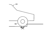
- 1 is an overall block diagram of a vehicle according to an embodiment. It is a 1st figure for demonstrating the problem at the time of getting over the level
- FIG. 1 is an overall block diagram of vehicle 100 according to the present embodiment.
- vehicle 100 includes a power storage device 110, a system main relay (hereinafter also referred to as SMR (System Main Relay)) 115, a PCU (Power Control Unit) 120 as a driving device, and a motor generator. 130, power transmission gear 140, drive wheel 150, and control device (hereinafter also referred to as ECU (Electronic Control Unit)) 300.
- SMR System Main Relay
- PCU Power Control Unit
- ECU Electronic Control Unit
- the power storage device 110 is a power storage element configured to be chargeable / dischargeable.
- the power storage device 110 includes, for example, a secondary battery such as a lithium ion battery, a nickel metal hydride battery, or a lead storage battery, and a power storage element such as an electric double layer capacitor.
- the power storage device 110 is connected to the PCU 120 for driving the motor generator 130 via the SMR 115. Then, power storage device 110 supplies power for generating driving force of vehicle 100 to PCU 120. The power storage device 110 stores the electric power generated by the motor generator 130.
- the output of power storage device 110 is, for example, 200V.
- the relays included in the SMR 115 are respectively inserted in the power lines PL1 and NL1 connecting the power storage device 110 and the PCU 120. SMR 115 switches between power supply and cutoff between power storage device 110 and PCU 120 based on control signal SE ⁇ b> 1 from ECU 300.
- the PCU 120 includes a converter, an inverter, etc., although none are shown.
- the converter is controlled by a control signal PWC from ECU 300 to convert the voltage from power storage device 110.
- the inverter is controlled by a control signal PWI from ECU 300 and drives motor generator 130 using electric power converted by the converter.
- the motor generator 130 is an AC rotating electric machine, for example, a permanent magnet type synchronous motor including a rotor in which a permanent magnet is embedded.
- the output torque of the motor generator 130 is transmitted to the drive wheels 150 via a power transmission gear 140 constituted by a speed reducer and a power split mechanism, thereby causing the vehicle 100 to travel.
- the motor generator 130 can generate electric power by the rotational force of the drive wheels 150 during the regenerative braking operation of the vehicle 100. Then, the generated power is converted into charging power for power storage device 110 by PCU 120.
- a necessary vehicle driving force is generated by operating the engine and the motor generator 130 in a coordinated manner.
- vehicle 100 in the present embodiment represents a vehicle equipped with an electric motor for generating vehicle driving force, and is a hybrid vehicle that generates vehicle driving force by an engine and an electric motor, an electric vehicle that is not equipped with an engine, and Includes fuel cell vehicles.
- a current sensor 160 is provided in a path connecting the PCU 120 and the motor generator 130.
- Current sensor 160 detects current MCRT flowing through motor generator 130 and outputs the detected value to ECU 300.
- the motor generator 130 is provided with a speed sensor 170 for detecting a signal related to the rotation speed of the motor generator 130.
- the speed sensor 170 includes, for example, a rotation angle sensor, detects the rotation angle of the rotor included in the motor generator 130, and detects the rotation speed of the motor generator 130 and / or the rotation speed of the drive wheel 150 based on the rotation angle sensor.
- the detected value SPD is output to ECU 300.
- speed sensor 170 may directly detect the speed of drive wheel 150 instead of motor generator 130.
- ECU 300 includes a CPU (Central Processing Unit), a storage device, and an input / output buffer (not shown in FIG. 1).
- the ECU 300 inputs a signal from each sensor and outputs a control signal to each device. 100 and each device are controlled. Note that these controls are not limited to processing by software, and can be processed by dedicated hardware (electronic circuit).
- ECU 300 receives detected values of voltage VB and current IB from a sensor (not shown) included in power storage device 110. ECU 300 calculates the state of charge of power storage device 110 (hereinafter also referred to as SOC (State of Charge)) based on voltage VB and current IB.
- SOC State of Charge
- the ECU 300 receives an operation signal from the user.
- the operation signal includes an operation amount ACC of the accelerator pedal 180, an operation amount BRK of the brake pedal 190, an operation signal PBK of the parking brake 200, and the like.
- ECU 300 is provided on the vehicle body and receives signal GS from inclination sensor 210 for detecting the inclination of the vehicle body.
- inclination sensor 210 for example, an acceleration sensor is used.
- the navigation system 220 may be mounted on the vehicle 100.
- ECU 300 receives vehicle information NAV including the position and movement information of vehicle 100 from navigation system 220.
- the drive wheel 150 is in a locked state in order to prevent equipment failure and deterioration that may occur due to excessive operation of the accelerator pedal. If this happens, the current flowing through the motor generator may be limited, that is, the torque may be limited.
- the torque limitation is achieved by overcoming the step and releasing the locked state of the drive wheels 150 as shown in FIG. When is released, more torque than necessary may be required.
- the step over control is executed to limit the speed of the vehicle for a predetermined period after overcoming the step.
- step-over control it is necessary to determine whether or not the vehicle is approaching a step.
- the driving wheel is locked as described above, and the driving wheel may not rotate even though the accelerator pedal is operated.
- a state can also occur, for example, when the vehicle is held in a stopped state due to the torque of the motor generator against the gravity on an uphill slope or when the vehicle starts on a slope. Therefore, it is important to appropriately determine whether the state in which the driving wheel does not rotate despite the operation of the accelerator pedal is due to a step or due to a slope.
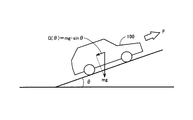
- FIG. 4 is a diagram for explaining a technique for detecting a step in the present embodiment.
- vehicle 100 is on a slope with an inclination angle ⁇
- mass of vehicle 100 is represented by m and gravity acceleration is represented by g
- component G ⁇ along the slope of gravity applied to vehicle 100 is represented.
- equation (1) can be expressed by the following equation (1).
- FIG. 5 is a diagram for explaining conditions for distinguishing a slope from a step.
- the torque required to perform the operation the operation time of the accelerator pedal when outputting such torque, And the output continuation time of the said torque is shown.
- the required torque is a torque that can output a force corresponding to the gravity component G ( ⁇ ) applied to the vehicle, and maintains the position of the vehicle. Therefore, the accelerator pedal operation time and the torque output time are relatively long.
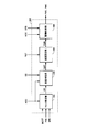
- FIG. 6 is a functional block diagram for explaining the step overstep control executed by ECU 300 in the present embodiment. Each functional block described in the functional block diagram of FIG. 6 is realized by hardware or software processing by ECU 300.
- ECU 300 includes a lock determination unit 310, a step determination unit 320, a speed setting unit 330, and a drive control unit 340.
- Lock determination unit 310 includes current MCRT of motor generator 130 detected by current sensor 160, rotation speed SPD of driving wheel 150 from speed sensor 170, operation amount ACC of accelerator pedal 180, and operation signal of parking brake 200. Receive PBK.
- the lock determination unit 310 determines whether or not the drive wheel 150 is in a locked state based on these pieces of information. Specifically, the drive wheel 150 is moving even when the accelerator pedal 180 is operated and / or the current is flowing through the motor generator 130 with the parking brake 200 released. If there is no state, it is determined that the state is locked.
- the state of the parking brake 200 is taken into account until, for example, when the vehicle starts to run on a slope, torque is generated on the drive wheels 150 to such an extent that the vehicle does not move backward in order to avoid the vehicle moving backward due to gravity. This is because the user may perform an operation to maintain a state in which a braking force is applied by the parking brake 200, and to prevent erroneous recognition due to such an operation.
- the lock determination unit 310 sets the determination signal LCK on when the driving wheel 150 is in a locked state, and sets the determination signal LCK off when the drive wheel 150 is not in a locked state. Then, lock determination section 310 outputs the determination signal LCK to step determination section 320.
- the level difference determination unit 320 receives the determination signal LCK from the lock determination unit 310, the operation amount ACC of the accelerator pedal 180, and the signal GS indicating the vehicle inclination from the inclination sensor 210.
- the step determining unit 320 determines the required torque determined from the road surface inclination determined from the signal GS indicating the inclination and the operation amount ACC of the accelerator pedal 180 when the driving wheel 150 is in the locked state. From the output continuation time of the required torque, it is determined whether or not the factor that the drive wheel 150 is in the locked state is due to a step.
- the level difference determination unit 320 sets a determination signal GAP indicating the presence or absence of a level difference and outputs it to the speed setting unit 330.
- the determination signal GAP is set to ON when there is a step, for example, and is set to OFF when there is no step.
- the speed setting unit 330 receives the determination signal GAP from the step determination unit 320 and sets the speed limit value VLIM of the vehicle 100. Specifically, when the determination signal GAP is OFF, that is, when there is no step, the speed setting unit 330 sets an upper limit value of the vehicle speed (vehicle speed) allowed during normal traveling as the speed limit value VLIM. To do. On the other hand, when the determination signal GAP is ON, that is, there is a step, the speed setting unit 330 is sufficiently smaller than the speed upper limit value of the vehicle speed in normal traveling so that a rapid increase in speed after overcoming the step is not performed. The speed limit value VLIM is set to the speed. Then, speed setting unit 330 outputs speed limit value VLIM to drive control unit 340.
- the speed setting unit 330 may, for example, perform a brake operation with the brake pedal 190 or the parking brake 200, a shift operation with a shift lever (not shown), or , A release signal caused by a travel end operation by an ignition key or an ignition switch, vehicle movement information included in the vehicle information NAV from the navigation system 220, information indicating that the operation amount ACC of the accelerator pedal 180 is equal to or less than a predetermined value, etc.
- the speed limit value VLIM is returned to the speed upper limit value during normal driving.
- the speed limit value VLIM is returned to the speed upper limit value during normal traveling when the operation amount ACC of the accelerator pedal 180 is zero. Is preferred.
- the drive control unit 340 receives the speed limit value VLIM from the speed setting unit 330, the operation amount ACC of the accelerator pedal 180, and the rotational speed SPD of the driving wheel 150 from the speed sensor 170.
- Drive control unit 340 generates converter and inverter control signals PWC and PWI included in PCU 120 such that the required torque determined from operation amount ACC of accelerator pedal 180 is output by motor generator 130.
- the drive control unit 340 controls the converter and the inverter while feedback controlling the rotational speed SPD of the drive wheels 150 so that the vehicle speed does not exceed the speed limit value VLIM set by the speed setting unit 330.
- FIG. 7 is a flowchart for explaining details of the step overcoming control process executed by ECU 300 in the present embodiment.
- the flowchart shown in FIG. 7 is realized by executing a program stored in advance in ECU 300 at a predetermined cycle. Alternatively, for some steps, it is also possible to construct dedicated hardware (electronic circuit) and realize processing.
- step S 100 determines in step (hereinafter, step is abbreviated as S) 100 whether PBK is off, that is, parking brake 200 is released.
- accelerator pedal 180 is depressed (YES in S110)
- the process proceeds to S120, and ECU 300 determines that drive wheel 150 is in a locked state based on rotational speed SPD of drive wheel 150 from speed sensor 170. It is determined whether or not there is.
- ECU 300 determines that vehicle 100 may have reached a step, advances the process to S130, and determines the amount of operation of accelerator pedal 180. Based on the ACC, the required torque TR from the user is calculated.
- the ECU 300 When the required torque TR is calculated in S130, the ECU 300 then needs to start the vehicle against the gravity in the direction along the inclination angle of the road surface in S140. It is determined whether or not the reference torque TCL is greater.
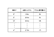
- the reference torque TCL is based on a signal GS from the inclination sensor 210 using a map that shows a relationship between the road inclination angle ⁇ and the reference torque TCL, which is predetermined by experiment or the like as shown in FIG. Set. Or you may obtain
- the relationship between the reference torque TCL and the operation amount ACC of the accelerator pedal 180 that can output the torque is obtained in advance by experiments or the like, and is actually operated by the user. Based on the operation amount ACC of the accelerator pedal 180 that is present, it may be determined whether or not the requested torque TR by the user is greater than the reference torque TCL. In this case, the calculation of the required torque TR in S130 is not necessary.
- ECU 300 determines whether or not the value of counter CNT is equal to or greater than a predetermined reference time Tth.
- ECU 300 does not need to limit the vehicle speed and thus ends the process.
- ECU 300 If vehicle 100 has not started (NO in S210), ECU 300 returns the process to S160 and waits for counter CNT to reach reference time Tth.
- ECU 300 sets vehicle speed limit value VLIM to a value sufficiently smaller than that during normal driving. Thus, even when the user has stepped on the accelerator pedal 180 too much after the vehicle has climbed over the level difference, it is possible to prevent the vehicle speed from increasing more than necessary.
- ECU 300 determines whether or not a release operation has been performed, for example, by operating brake pedal 190, as described in FIG.
- ECU 300 is in a case where the user is still over the step, or a case where the user continues to step on accelerator pedal 180 after the step is over.
- the processing is returned to S180, and the user waits for the canceling operation by the user while maintaining the state where the speed limit value VLIM is set to be small.
- ECU 300 determines that the step over has been completed. Then, the process proceeds to S200, and ECU 300 returns speed limit value VLIM to the speed upper limit value during normal travel, and ends the process.
- the speed limit value setting is lowered when the vehicle is over the level difference.
- the speed limit value setting is not changed, but the operation amount of the accelerator pedal is supported.
- the upper limit value of the speed may be reduced as a result by reducing the required torque and the required output to be reduced as compared with the normal running.
Landscapes
- Engineering & Computer Science (AREA)
- Power Engineering (AREA)
- Mechanical Engineering (AREA)
- Transportation (AREA)
- Life Sciences & Earth Sciences (AREA)
- Sustainable Development (AREA)
- Sustainable Energy (AREA)
- Chemical & Material Sciences (AREA)
- Combustion & Propulsion (AREA)
- General Engineering & Computer Science (AREA)
- Electric Propulsion And Braking For Vehicles (AREA)
Abstract
Description
好ましくは、車両は、アクセルペダルをさらに備える。制御装置は、車両の駆動輪の回転速度に関するパラメータが所定値以下であり、かつ、アクセルペダルの操作量が、車両の傾きに対応する所定の操作量よりも大きいという所定条件のときには、段差を乗り越える状態であるとして、段差を乗り越える状態でないときよりも、車両の走行速度の上限値が低い値に制限されるように駆動装置を制御する。
この重力成分G(θ)は、傾斜角θが大きくなるにつれて増加する。そして、車両100が、モータジェネレータのトルクにより斜面上で停止状態を保持する場合、あるいは坂路を登る場合には、この重力成分G(θ)以上の力となるようなトルクを出力することが必要となる。
Claims (7)
- 搭載した回転電機(130)により出力される駆動力を用いて走行が可能な車両であって、
前記回転電機(130)を駆動するための駆動装置(120)と、
前記駆動装置(120)を制御するための制御装置(300)とを備え、
前記制御装置(300)は、前記車両(100)が路面の段差を乗り越える状態であるときには、前記段差を乗り越える状態でないときよりも、前記車両(100)の走行速度の上限値が低い値に制限されるように前記駆動装置(120)を制御する、車両。 - アクセルペダル(180)をさらに備え、
前記制御装置(300)は、前記車両(100)の駆動輪(150)の回転速度に関するパラメータが所定値以下であり、かつ、前記アクセルペダル(180)の操作量が、前記車両(100)の傾きに対応する所定の操作量よりも大きいという所定条件のときには、前記段差を乗り越える状態であるとして、前記段差を乗り越える状態でないときよりも、前記車両(100)の走行速度の上限値が低い値に制限されるように前記駆動装置(120)を制御する、請求項1に記載の車両。 - 前記制御装置(300)は、前記所定条件が成立し、さらに前記所定条件が予め定められた期間継続した場合に、前記段差を乗り越える状態であると判定する、請求項2に記載の車両。
- 前記制御装置(300)は、前記段差を乗り越える状態が終了したことを示す情報に基づいて、前記車両(100)の走行速度の制限を解除する、請求項1に記載の車両。
- アクセルペダル(180)をさらに備え、
前記段差を乗り越える状態が終了したことを示す情報は、ユーザによるブレーキ操作情報、シフトレンジ変更操作情報、走行終了操作情報、および前記アクセルペダル(180)の操作量が所定以下であることを示す情報の少なくとも1つを含む、請求項4に記載の車両。 - ナビゲーションシステム(220)をさらに備え、
前記段差を乗り越える状態が終了したことを示す情報は、前記ナビゲーションシステム(220)からの信号に基づく前記車両(100)の移動情報をさらに含む、請求項5に記載の車両。 - 搭載した回転電機(130)により出力される駆動力を用いて走行が可能な車両の制御方法であって、
前記車両(100)は、前記回転電機(130)を駆動するための駆動装置(120)を含み、
前記制御方法は、
前記車両(100)が路面の段差を乗り越える状態であることを検出するステップと、
前記段差を乗り越える状態であるときには、前記段差を乗り越える状態でないときよりも、前記車両(100)の走行速度の上限値が低い値に制限されるように前記駆動装置(120)を制御するステップとを備える、制御方法。
Priority Applications (4)
| Application Number | Priority Date | Filing Date | Title |
|---|---|---|---|
| US14/007,570 US20140019027A1 (en) | 2011-04-01 | 2011-04-01 | Vehicle and method for controlling vehicle |
| CN2011800697439A CN103476631A (zh) | 2011-04-01 | 2011-04-01 | 车辆和车辆的控制方法 |
| PCT/JP2011/058430 WO2012137278A1 (ja) | 2011-04-01 | 2011-04-01 | 車両および車両の制御方法 |
| JP2013508640A JPWO2012137278A1 (ja) | 2011-04-01 | 2011-04-01 | 車両および車両の制御方法 |
Applications Claiming Priority (1)
| Application Number | Priority Date | Filing Date | Title |
|---|---|---|---|
| PCT/JP2011/058430 WO2012137278A1 (ja) | 2011-04-01 | 2011-04-01 | 車両および車両の制御方法 |
Publications (1)
| Publication Number | Publication Date |
|---|---|
| WO2012137278A1 true WO2012137278A1 (ja) | 2012-10-11 |
Family
ID=46968719
Family Applications (1)
| Application Number | Title | Priority Date | Filing Date |
|---|---|---|---|
| PCT/JP2011/058430 Ceased WO2012137278A1 (ja) | 2011-04-01 | 2011-04-01 | 車両および車両の制御方法 |
Country Status (4)
| Country | Link |
|---|---|
| US (1) | US20140019027A1 (ja) |
| JP (1) | JPWO2012137278A1 (ja) |
| CN (1) | CN103476631A (ja) |
| WO (1) | WO2012137278A1 (ja) |
Cited By (2)
| Publication number | Priority date | Publication date | Assignee | Title |
|---|---|---|---|---|
| WO2015141286A1 (ja) * | 2014-03-20 | 2015-09-24 | 日産自動車株式会社 | ハイブリッド車両の制御装置 |
| JP2021030745A (ja) * | 2019-08-14 | 2021-03-01 | 本田技研工業株式会社 | 車両制御装置及び車両 |
Families Citing this family (15)
| Publication number | Priority date | Publication date | Assignee | Title |
|---|---|---|---|---|
| DE102011081707A1 (de) * | 2011-08-29 | 2013-02-28 | Robert Bosch Gmbh | Verfahren zur Unterstützung eines Fahrers eines Kraftfahrzeugs |
| ES2972160T3 (es) * | 2014-01-16 | 2024-06-11 | Polestar Performance Ab | Un vehículo adaptado para la conducción autónoma y un método para detectar objetos obstructores |
| JP5949840B2 (ja) * | 2014-06-19 | 2016-07-13 | トヨタ自動車株式会社 | 駐車支援装置 |
| JP2016182005A (ja) * | 2015-03-24 | 2016-10-13 | 株式会社デンソー | 制御装置 |
| JP6559330B2 (ja) * | 2016-03-30 | 2019-08-14 | 日立オートモティブシステムズ株式会社 | 車両制御装置 |
| JP6536508B2 (ja) * | 2016-07-22 | 2019-07-03 | トヨタ自動車株式会社 | 駐車支援装置 |
| KR102651860B1 (ko) * | 2016-10-26 | 2024-03-27 | 주식회사 에이치엘클레무브 | 자동 주차 시스템 및 방법 |
| JP6981196B2 (ja) * | 2017-11-17 | 2021-12-15 | 株式会社アドヴィックス | 車両の走行支援装置 |
| JP6984558B2 (ja) * | 2018-07-26 | 2021-12-22 | トヨタ自動車株式会社 | 車両走行支援装置 |
| JP7091913B2 (ja) * | 2018-07-26 | 2022-06-28 | トヨタ自動車株式会社 | 車両走行支援装置 |
| KR102886281B1 (ko) * | 2020-12-14 | 2025-11-13 | 현대자동차주식회사 | 차량의 과속방지턱 통과 시 제어 방법 |
| CN112693556B (zh) * | 2021-01-19 | 2022-03-11 | 北京三快在线科技有限公司 | 电动车辆及其运动控制装置、控制方法 |
| JP7440708B2 (ja) * | 2021-08-27 | 2024-02-28 | 株式会社Subaru | ハイブリッド全輪駆動車 |
| WO2024008846A1 (de) * | 2022-07-06 | 2024-01-11 | Robert Bosch Gmbh | Verfahren zur steuerung einer antriebseinheit eines fahrzeugs |
| TWI879199B (zh) * | 2023-11-01 | 2025-04-01 | 財團法人工業技術研究院 | 氫氣洩漏監測系統、應用其之車輛及氫氣洩漏監測方法 |
Citations (4)
| Publication number | Priority date | Publication date | Assignee | Title |
|---|---|---|---|---|
| JPH0974617A (ja) * | 1995-09-07 | 1997-03-18 | Toyota Autom Loom Works Ltd | 電動車両の駆動制御機構 |
| JP2007045230A (ja) * | 2005-08-08 | 2007-02-22 | Nissan Motor Co Ltd | ハイブリッド車両の段差乗り越え発進時駆動力制御装置 |
| JP2007230343A (ja) * | 2006-02-28 | 2007-09-13 | Hitachi Ltd | 四輪駆動車両 |
| JP2008174102A (ja) * | 2007-01-18 | 2008-07-31 | Toyota Motor Corp | 駐車支援装置 |
Family Cites Families (9)
| Publication number | Priority date | Publication date | Assignee | Title |
|---|---|---|---|---|
| JPH04355605A (ja) * | 1991-05-30 | 1992-12-09 | Honda Motor Co Ltd | 電動車輌の駆動出力制御方法 |
| JPH0595109U (ja) * | 1992-05-29 | 1993-12-24 | 三菱自動車工業株式会社 | 電気自動車用電動機の後退時制御 |
| JP3450078B2 (ja) * | 1995-01-30 | 2003-09-22 | セイコーエプソン株式会社 | 電気自動車のパワーアシスト装置 |
| US6907337B2 (en) * | 2003-09-11 | 2005-06-14 | Ford Global Technologies, Llc | Vehicle torque resolution |
| JP2006296135A (ja) * | 2005-04-13 | 2006-10-26 | Toyota Motor Corp | 駐車支援装置 |
| JP4449873B2 (ja) * | 2005-09-26 | 2010-04-14 | 日産自動車株式会社 | 車両の発進時段差乗り越え検出装置および段差乗り越え発進時駆動力制御装置 |
| CN101209682B (zh) * | 2006-12-26 | 2010-09-29 | 比亚迪股份有限公司 | 电动汽车爬坡状态下电机输出转矩控制系统及控制方法 |
| JP4894808B2 (ja) * | 2008-03-31 | 2012-03-14 | 株式会社エクォス・リサーチ | 車両 |
| JP5109101B2 (ja) * | 2009-09-17 | 2012-12-26 | 日立オートモティブシステムズ株式会社 | 車両制御装置 |
-
2011
- 2011-04-01 CN CN2011800697439A patent/CN103476631A/zh active Pending
- 2011-04-01 WO PCT/JP2011/058430 patent/WO2012137278A1/ja not_active Ceased
- 2011-04-01 JP JP2013508640A patent/JPWO2012137278A1/ja active Pending
- 2011-04-01 US US14/007,570 patent/US20140019027A1/en not_active Abandoned
Patent Citations (4)
| Publication number | Priority date | Publication date | Assignee | Title |
|---|---|---|---|---|
| JPH0974617A (ja) * | 1995-09-07 | 1997-03-18 | Toyota Autom Loom Works Ltd | 電動車両の駆動制御機構 |
| JP2007045230A (ja) * | 2005-08-08 | 2007-02-22 | Nissan Motor Co Ltd | ハイブリッド車両の段差乗り越え発進時駆動力制御装置 |
| JP2007230343A (ja) * | 2006-02-28 | 2007-09-13 | Hitachi Ltd | 四輪駆動車両 |
| JP2008174102A (ja) * | 2007-01-18 | 2008-07-31 | Toyota Motor Corp | 駐車支援装置 |
Cited By (5)
| Publication number | Priority date | Publication date | Assignee | Title |
|---|---|---|---|---|
| WO2015141286A1 (ja) * | 2014-03-20 | 2015-09-24 | 日産自動車株式会社 | ハイブリッド車両の制御装置 |
| JPWO2015141286A1 (ja) * | 2014-03-20 | 2017-04-06 | 日産自動車株式会社 | ハイブリッド車両の制御装置 |
| US9963141B2 (en) | 2014-03-20 | 2018-05-08 | Nissan Motor Co., Ltd. | Hybrid vehicle control device with transmission control for a level difference of a road surface |
| JP2021030745A (ja) * | 2019-08-14 | 2021-03-01 | 本田技研工業株式会社 | 車両制御装置及び車両 |
| JP7174679B2 (ja) | 2019-08-14 | 2022-11-17 | 本田技研工業株式会社 | 車両制御装置及び車両 |
Also Published As
| Publication number | Publication date |
|---|---|
| JPWO2012137278A1 (ja) | 2014-07-28 |
| CN103476631A (zh) | 2013-12-25 |
| US20140019027A1 (en) | 2014-01-16 |
Similar Documents
| Publication | Publication Date | Title |
|---|---|---|
| WO2012137278A1 (ja) | 車両および車両の制御方法 | |
| JP5708797B2 (ja) | 電動車両 | |
| JP4315094B2 (ja) | ハイブリッド車のエンジン始動制御装置 | |
| JP5817761B2 (ja) | 電子制御装置 | |
| JP2012180004A (ja) | 車両および車両の制御方法 | |
| JP5765194B2 (ja) | 車両および車両の制御方法 | |
| JP5656736B2 (ja) | 車両および車両の制御方法 | |
| JP5843412B2 (ja) | アクセルペダル反力制御装置及び車両 | |
| JP5891774B2 (ja) | ハイブリッド車 | |
| JP2015016810A (ja) | 車両の制御システム | |
| JP2011093335A (ja) | ハイブリッド車両の制御装置 | |
| CN103476625A (zh) | 电动车辆及其控制方法 | |
| JP2010064499A (ja) | ハイブリッド車両 | |
| CN113085829A (zh) | 混合动力车辆、行驶控制系统和控制混合动力车辆的方法 | |
| JP4055758B2 (ja) | 自動車およびその制御方法 | |
| CN109941270A (zh) | 混合动力汽车 | |
| JP2012232671A (ja) | 車両 | |
| JP5829872B2 (ja) | 車両 | |
| JP2011126321A (ja) | ハイブリッド電気自動車の制御装置 | |
| WO2012137301A1 (ja) | 車両およびその制御方法 | |
| JP2014162319A (ja) | 電動車両のパーキング装置 | |
| JP5927792B2 (ja) | 車両用制御装置および車両用制御方法 | |
| JP2009185854A (ja) | 自動車およびその制御方法 | |
| JP2015231757A (ja) | ハイブリッド車両 | |
| CN112389416A (zh) | 车辆控制装置和车辆 |
Legal Events
| Date | Code | Title | Description |
|---|---|---|---|
| 121 | Ep: the epo has been informed by wipo that ep was designated in this application |
Ref document number: 11863167 Country of ref document: EP Kind code of ref document: A1 |
|
| ENP | Entry into the national phase |
Ref document number: 2013508640 Country of ref document: JP Kind code of ref document: A |
|
| WWE | Wipo information: entry into national phase |
Ref document number: 14007570 Country of ref document: US |
|
| NENP | Non-entry into the national phase |
Ref country code: DE |
|
| 122 | Ep: pct application non-entry in european phase |
Ref document number: 11863167 Country of ref document: EP Kind code of ref document: A1 |