WO2012133790A1 - 蓄熱装置及び蓄熱装置を備えるシステム - Google Patents
蓄熱装置及び蓄熱装置を備えるシステム Download PDFInfo
- Publication number
- WO2012133790A1 WO2012133790A1 PCT/JP2012/058613 JP2012058613W WO2012133790A1 WO 2012133790 A1 WO2012133790 A1 WO 2012133790A1 JP 2012058613 W JP2012058613 W JP 2012058613W WO 2012133790 A1 WO2012133790 A1 WO 2012133790A1
- Authority
- WO
- WIPO (PCT)
- Prior art keywords
- heat
- alloy
- temperature
- heat storage
- storage device
- Prior art date
- Legal status (The legal status is an assumption and is not a legal conclusion. Google has not performed a legal analysis and makes no representation as to the accuracy of the status listed.)
- Ceased
Links
Images













Classifications
-
- F—MECHANICAL ENGINEERING; LIGHTING; HEATING; WEAPONS; BLASTING
- F28—HEAT EXCHANGE IN GENERAL
- F28D—HEAT-EXCHANGE APPARATUS, NOT PROVIDED FOR IN ANOTHER SUBCLASS, IN WHICH THE HEAT-EXCHANGE MEDIA DO NOT COME INTO DIRECT CONTACT
- F28D20/00—Heat storage plants or apparatus in general; Regenerative heat-exchange apparatus not covered by groups F28D17/00 or F28D19/00
- F28D20/02—Heat storage plants or apparatus in general; Regenerative heat-exchange apparatus not covered by groups F28D17/00 or F28D19/00 using latent heat
- F28D20/026—Heat storage plants or apparatus in general; Regenerative heat-exchange apparatus not covered by groups F28D17/00 or F28D19/00 using latent heat with different heat storage materials not coming into direct contact
-
- C—CHEMISTRY; METALLURGY
- C09—DYES; PAINTS; POLISHES; NATURAL RESINS; ADHESIVES; COMPOSITIONS NOT OTHERWISE PROVIDED FOR; APPLICATIONS OF MATERIALS NOT OTHERWISE PROVIDED FOR
- C09K—MATERIALS FOR MISCELLANEOUS APPLICATIONS, NOT PROVIDED FOR ELSEWHERE
- C09K5/00—Heat-transfer, heat-exchange or heat-storage materials, e.g. refrigerants; Materials for the production of heat or cold by chemical reactions other than by combustion
-
- C—CHEMISTRY; METALLURGY
- C09—DYES; PAINTS; POLISHES; NATURAL RESINS; ADHESIVES; COMPOSITIONS NOT OTHERWISE PROVIDED FOR; APPLICATIONS OF MATERIALS NOT OTHERWISE PROVIDED FOR
- C09K—MATERIALS FOR MISCELLANEOUS APPLICATIONS, NOT PROVIDED FOR ELSEWHERE
- C09K5/00—Heat-transfer, heat-exchange or heat-storage materials, e.g. refrigerants; Materials for the production of heat or cold by chemical reactions other than by combustion
- C09K5/02—Materials undergoing a change of physical state when used
- C09K5/06—Materials undergoing a change of physical state when used the change of state being from liquid to solid or vice versa
- C09K5/063—Materials absorbing or liberating heat during crystallisation; Heat storage materials
-
- H—ELECTRICITY
- H10—SEMICONDUCTOR DEVICES; ELECTRIC SOLID-STATE DEVICES NOT OTHERWISE PROVIDED FOR
- H10N—ELECTRIC SOLID-STATE DEVICES NOT OTHERWISE PROVIDED FOR
- H10N10/00—Thermoelectric devices comprising a junction of dissimilar materials, i.e. devices exhibiting Seebeck or Peltier effects
- H10N10/10—Thermoelectric devices comprising a junction of dissimilar materials, i.e. devices exhibiting Seebeck or Peltier effects operating with only the Peltier or Seebeck effects
- H10N10/13—Thermoelectric devices comprising a junction of dissimilar materials, i.e. devices exhibiting Seebeck or Peltier effects operating with only the Peltier or Seebeck effects characterised by the heat-exchanging means at the junction
-
- Y—GENERAL TAGGING OF NEW TECHNOLOGICAL DEVELOPMENTS; GENERAL TAGGING OF CROSS-SECTIONAL TECHNOLOGIES SPANNING OVER SEVERAL SECTIONS OF THE IPC; TECHNICAL SUBJECTS COVERED BY FORMER USPC CROSS-REFERENCE ART COLLECTIONS [XRACs] AND DIGESTS
- Y02—TECHNOLOGIES OR APPLICATIONS FOR MITIGATION OR ADAPTATION AGAINST CLIMATE CHANGE
- Y02E—REDUCTION OF GREENHOUSE GAS [GHG] EMISSIONS, RELATED TO ENERGY GENERATION, TRANSMISSION OR DISTRIBUTION
- Y02E60/00—Enabling technologies; Technologies with a potential or indirect contribution to GHG emissions mitigation
- Y02E60/14—Thermal energy storage
Definitions
- the present invention relates to a heat storage device including an alloy or a mixed salt having a predetermined eutectic temperature and a system including the heat storage device.
- Patent Document 1 discloses a heat treatment apparatus in which a temperature setting layer set to a predetermined temperature is provided between two thermoelectric conversion modules that generate electricity from heat.
- Patent Document 2 discloses a thermoelectric power generation system in which an intermediate heat transfer loop capable of controlling a heat flow is provided between a high-temperature side and a low-temperature side power generation element.
- an alloy or mixed salt having a eutectic reaction increases in temperature when heated and decreases in temperature when heating is stopped, but the temperature change becomes gentle in the vicinity of the eutectic point.
- a heat storage device using such an alloy or a mixed salt can be provided between a heat source that generates exhaust heat and an energy conversion device such as a thermoelectric conversion module, heat in a constant temperature range near the eutectic point can be obtained. Can be stably supplied to the energy conversion device.
- This invention is made
- a heat-resistant frame filled with one kind of alloy or mixed salt having a predetermined eutectic temperature, or two or more kinds of alloys or mixed salts having different eutectic temperatures are divided into barriers in order of the eutectic temperature.
- a heat storage device comprising a heat-resistant frame filled adjacent to each other.
- the heat-resistant frame body filled with the alloy (1) or the mixed salt (1) having the highest eutectic temperature is used as the heat absorbing part, and the alloy having the lowest eutectic temperature (
- a system comprising: the heat storage device according to (2); and an energy conversion device connected to the heat radiating unit.
- a system comprising the heat storage device according to (3) and an energy conversion device connected to the heat radiating unit.
- thermoelectric conversion module (8) The system according to (6) or (7), wherein the energy conversion device is a thermoelectric conversion module.
- thermoelectric conversion module (11) A method in which the system described in (8) is used to store heat by absorbing heat in the heat absorbing unit, and the thermoelectric conversion module generates power using heat released from the heat radiating unit as a heat source.
- the heat storage apparatus which can store the heat
- released from the said thermal storage apparatus can be provided.
- the energy conversion device is a thermoelectric conversion module, it is possible to provide a power generation system capable of maintaining a constant power generation amount by heat in a constant temperature range released from the heat storage device.
- FIG. 2 shows a phase diagram of a Sn—Zn alloy which is an example of an alloy according to the present embodiment. It is a figure which shows typically the thermal storage apparatus which concerns on the modification 1. As shown in FIG. It is a figure which shows typically the thermal storage apparatus which concerns on the modification 2. As shown in FIG. It is a figure which shows typically the heat storage apparatus which concerns on the modification 3. It is a figure which shows typically the heat storage apparatus which concerns on the modification 4. It is a figure showing typically an example of the thermal energy conversion system concerning the embodiment of the present invention.
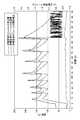
- Example 1 it is a figure which shows the position which provided the thermocouple in the thermal storage apparatus. It is a figure which shows the temperature change of the predetermined location in Example 1.
- FIG. 2-9 it is a figure which shows the position which provided the thermocouple in the thermal storage apparatus or the thermal energy conversion system.
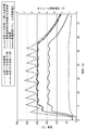
- FIG. 2 It is a figure which shows the temperature change of the predetermined location of the thermal storage apparatus in Example 2.
- FIG. It is a figure which shows the temperature change of the predetermined location of the thermal storage apparatus in Example 3.
- FIG. It is a figure which shows the temperature change of the predetermined location of the thermal storage apparatus in Example 4.
- FIG. It is a figure which shows the temperature change of the predetermined location of the thermal storage apparatus in Example 5.
- FIG. It is a figure which shows the temperature change of the predetermined location of the thermal storage apparatus in Example 6.
- FIG. It is a figure which shows the temperature change of the predetermined location of the thermal energy conversion system in Example 7, and the change of the open circuit voltage of a thermoelectric conversion module.
- Example 10 It is a figure which shows the temperature change of the predetermined location of the thermal energy conversion system in Example 8, and the change of the open circuit voltage of a thermoelectric conversion module. It is a figure which shows the temperature change of the predetermined location of the thermal energy conversion system in Example 9, and the change of the open circuit voltage of a thermoelectric conversion module.
- Example 10 it is a figure which shows the position which provided the thermocouple in the thermal energy conversion system.
- Example 10 it is a figure which shows the temperature change of the predetermined location of the thermal energy conversion system in Example 10.
- FIG. It is a figure which shows typically the thermal energy conversion system in Example 11.
- FIG. It is a figure which shows the temperature change of the predetermined location of the thermal energy conversion system in Example 11, and the change of the open circuit voltage of a thermoelectric conversion module.
- FIG. 12 It is a figure which shows typically the thermal energy conversion system in Example 12.
- FIG. 12 is a figure which shows the temperature change of the predetermined location of the thermal energy conversion system in Example 12, and the change of the open circuit voltage of a thermoelectric conversion module.
- It is a figure which shows the thermal energy conversion system in Example 13 typically.
- FIG. shows typically the thermal energy conversion system in Example 14.
- FIG. It is a figure which shows the temperature change of the predetermined location of the thermal energy conversion system in Example 14, and the change of the open circuit voltage of a thermoelectric conversion module.
- FIG. It is a figure which shows the temperature change of the predetermined location of the thermal energy conversion system in Example 15, and the change of the open circuit voltage of a thermo
- the heat storage device of the present invention is a device that accumulates heat obtained from a heat source with unstable temperature by latent heat.
- the heat storage device of the present invention stores heat with an alloy or mixed salt having a predetermined eutectic temperature, and this alloy or mixed salt may be one kind or plural kinds.
- the heat storage device 10 according to the first embodiment of the present invention described below uses two types of alloys as an example of the heat storage device of the present invention.
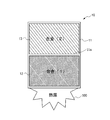
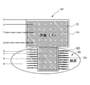
- FIG. 1 is a diagram schematically illustrating an example of a heat storage device 10 according to an embodiment of the present invention.
- the heat storage device 10 includes a box-shaped heat-resistant frame 11, a heat-absorption-side heat storage unit 12 formed by filling the heat-resistant frame 11 on the heat source 100 side with the alloy (1), and a heat-absorption-side heat storage unit 12. And a heat-radiating side heat storage section 13 that is formed by filling the inside of the heat-resistant frame 11 with the alloy (2).
- the heat-resistant frame 11 is a box-like body and has a predetermined capacity space inside.
- the heat resistant frame 11 has a partition wall 11a that divides the inside of the heat resistant frame 11 into two equal parts in the depth direction. That is, the heat resistant frame 11 has two spaces of a predetermined capacity that are adjacent to each other through the partition wall 11a.
- the heat-resistant frame 11 which concerns on this embodiment is formed in the box-shaped body, in this invention, it can be set as the shape which can be filled with alloys, such as not only a box-shaped body but a tubular body.
- the inside of the heat resistant frame 11 according to the present embodiment is divided into two equal parts, the present invention is not limited to two equal parts, and can be divided by a volume ratio according to the characteristics of the alloy to be filled. .
- the partition wall 11a can be omitted.
- the heat resistant frame 11 has one space.
- the heat-resistant frame 11 can have a surface on the side opposite to the surface in contact with the heat absorption side heat storage unit 12 in the heat radiation side heat storage unit 13 wider than the surface in contact with the heat absorption side heat storage unit 12.
- the heat resistant frame 11 is formed of a heat resistant material (for example, SS, SUS, SCH, SCS, etc.) having a predetermined thickness.
- the heat-resistant frame 11 includes a box portion that forms two spaces and has one surface opened, and a lid portion that closes the opened surface of the box portion.
- the heat absorption side heat storage section 12 is formed by filling the space on the heat source 100 side among the two spaces of the heat resistant frame 11 with the alloy (1).
- the heat radiation side heat storage unit 13 is formed by filling the space on the opposite side to the heat source 100 side of the two spaces of the heat resistant frame 11 with the alloy (2).
- the heat absorption side heat storage unit 12 and the heat radiation side heat storage unit 13 are directly filled with the alloy (1) or the alloy (2) in the heat resistant frame 11, but the present invention is not limited to this,
- Each of the heat absorption side heat storage unit 12 and the heat radiation side heat storage unit 13 includes an individual frame, and the frame is filled with the alloy (1) or the alloy (2), and the alloy (1) or the alloy (2) is filled.
- the frame body can also be detachably attached to the heat-resistant frame body 11.
- the eutectic temperature of the alloy (1) of the heat absorption side heat storage unit 12 is higher than the eutectic temperature of the alloy (2) of the heat dissipation side heat storage unit 13.
- the alloy (1) absorbs fluctuations in the temperature and amount of heat generated by the heat source 100, and supplies heat in a predetermined temperature range to the alloy (2).
- the alloy (2) absorbs the temperature change of the heat supplied from the alloy (1) and stores heat in a predetermined temperature range.
- the alloy (1) and the alloy (2) are alloys having a predetermined eutectic temperature, and an alloy whose eutectic temperature is included in the temperature range of heat generated by the heat source 100 is selected.
- the temperature range of heat generated by the heat source 100 is the range from T1 to T2 in FIG. 2, and the dimensionless figure of merit ZT of the thermoelectric conversion module connected to the heat storage device 10 is shown in FIG.
- the eutectic temperature is It is preferable to select those in the range of T5 to T6 in 2.
- heat in a temperature range in which the dimensionless figure of merit ZT is the highest can be transmitted to the thermoelectric conversion module.
- FIG. 3 shows a phase diagram of a Sn—Zn alloy which is an example of the alloy according to the present embodiment.
- the eutectic temperature of the Sn—Zn alloy which is an example of the alloy according to the present embodiment is 199 ° C.
- the alloy absorbs heat when the alloy temperature is heated higher than 199 ° C., and the eutectic temperature is lower than 199 ° C. To dissipate heat.
- the amount of heat absorbed and generated by the alloy can be adjusted by changing the heat capacity (specific heat x specific gravity x volume) + melting enthalpy of the alloy. For example, when it is desired to increase the endothermic amount and the calorific value, it is possible to increase the endothermic amount and the calorific value of the alloy by composing the alloy with a metal having a higher specific gravity and melting enthalpy or increasing the volume. it can.
- the alloys of the heat absorption side heat storage unit 12 and the heat radiation side heat storage unit 13 are different from each other, but the present invention is not limited to this, and the alloy of the heat absorption side heat storage unit 12 and the heat radiation side heat storage unit 13 is the same. It can be the same. In this case, the partition 11a of the heat resistant frame 11 is not provided, and the space of the heat resistant frame 11 can be made one.
- the space inside the heat-resistant frame 11 is divided into two equal parts, and these two spaces are filled with two types of alloys.
- the present invention is not limited to this, and the heat-resistant frame 11
- the space inside the body 11 can be divided into three or more spaces, and these spaces can be filled with different alloys. In this case, the alloy is filled in descending order of the eutectic temperature from the heat source 100 side.
- the present invention is not limited to this, and the heat absorption side heat storage part 12 and the heat radiation side heat storage part 13 are mixed. It can be filled with salt.
- Table 1 shows specific examples of the low temperature alloy (1) and the alloy (2).
- Low temperature is an alloy used when the temperature of heat generated from the heat source 100 is up to 400 ° C.
- Table 2 shows specific examples of alloys for low temperatures other than the alloys shown in Table 1 and mixed salts for low temperatures.
- Table 3 shows specific examples of the alloy (1) and the alloy (2) for medium temperature.
- the medium temperature is an alloy used when the temperature of heat generated from the heat source 100 is up to 800 ° C.
- Table 4 shows specific examples of alloys for medium temperature and mixed salts for medium temperature other than the alloys shown in Table 3.
- Table 5 shows specific examples of the alloy (1) and the alloy (2) for high temperature.
- the high temperature is an alloy used when the temperature of heat generated from the heat source 100 is up to 1000 ° C.
- Table 6 shows specific examples of alloys for high temperatures other than the alloys shown in Table 5.
- the manufacturing method of the thermal storage apparatus 10 A method for manufacturing the heat storage device 10 will be described. First, the heat-resistant frame 11 having two spaces forming the heat absorption side heat storage part 12 and the heat radiation side heat storage part 13 is manufactured by dividing it into a box part and a lid part. Next, according to the temperature range of the heat generated in the heat source 100, the alloy type of the alloy (1) and the alloy (2) is selected. Two kinds of single metals composing the alloy (1) are mixed at a predetermined weight ratio, melted by heating in a crucible furnace, and poured into a space forming the heat absorption side heat storage section 12 in the box section.
- two kinds of single metals composing the alloy (2) are blended at a predetermined weight ratio, melted by heating in a crucible furnace, and poured into a space forming the heat radiation side heat storage section 13 in the box section. .
- a lid is attached to the box.
- a heat insulating material may be wound around the heat storage device 10 to prevent heat loss.
- the alloy (2) When the temperature rises to the eutectic temperature, the alloy (2) maintains that temperature for a certain period of time, and then enters a solid-liquid coexistence state, so that the temperature rises gradually.
- the thermoelectric conversion module is attached to the heat storage device 10, the heat of the alloy (2) is transmitted to the thermoelectric conversion module.
- the heat storage device 10 can absorb the temperature fluctuation of heat by the endothermic / exothermic reaction near the eutectic temperature, but the alloy (1) and / or the alloy (2) performs the eutectic reaction and the eutectoid reaction. In the case of having it, the temperature variation of heat can be absorbed also by the endothermic / exothermic reaction near the eutectoid temperature.
- FIG. 4 is a diagram schematically illustrating a heat storage device 10A according to the first modification.
- the heat collection component 12b is provided in the heat absorption side heat storage section 12A.
- the volume ratio of the alloy (1) and the alloy (2) in the heat storage device 10A is approximately 3: 7.
- the heat absorption side heat storage part 12A includes a portion in which the space on the heat source 100 side in the two spaces divided by the partition wall 11a of the heat resistant frame 11 is filled with the alloy (1), and a tubular shape in which the alloy (1) is filled.
- the heat collection component 12b is a component that absorbs heat of gas or liquid, and is a fin that increases an area in contact with the gas.
- the heat absorbed by the heat collecting component 12b is transmitted to the tubular body 12a and absorbed by the alloy (1) filled in the tubular body 12a.
- the efficiency of heat absorption can be improved when heat is absorbed from gas or liquid.
- fins are shown as a specific mode of the heat collecting component 12 b, but the mode of the heat collecting component 12 b is not limited to fins, and may be a bellows-like tubular body, for example. .
- FIG. 5 is a diagram schematically illustrating a heat storage device 10A ′ according to the second modification.
- Modification 2 differs from Modification 1 in that the heat-resistant frame is not provided with partition walls, and the space and tubular body of the heat-resistant frame are filled with one type of alloy.
- the heat storage device 10A ′ includes a heat-resistant frame 11A having one space, a tubular body 12a, and a heat collecting component 12b formed in a spiral shape on the outer periphery of the tubular body 12a.
- the space and the tubular body 12a are filled with the same kind of alloy (1).
- FIG. 6 is a diagram schematically illustrating a heat storage device 10B according to the third modification.
- a temperature fuse 15 is provided on the heat source 100 side of the heat absorption side heat storage unit 12.
- the volume ratio of the alloy (1) and the alloy (2) in the heat storage device 10B is approximately 4: 6.
- the thermal fuse 15 includes a soluble alloy 15a that melts at a predetermined temperature and a holding member 15b that holds the soluble alloy 15a.
- the soluble alloy 15a is formed of an alloy that melts near the temperature at which the alloy (1) can absorb heat.
- the melting point of the soluble alloy 15a only needs to be higher than the eutectic temperature of the alloy (1) and lower than the melting point of the alloy (1).
- the holding member 15b is formed of, for example, copper or the like having a melting point higher than that of the alloy (1) for high temperature (maximum 1000 ° C.).
- the thermal fuse 15 absorbs the heat and transmits this heat to the alloy (1), and the temperature of the heat generated from the heat source 100.
- the temperature exceeds the temperature at which the alloy (1) can absorb heat the soluble alloy 15a is melted and heat is prevented from being transferred to the alloy (1).
- the temperature fuse 15 is provided between the heat storage device 10 and the heat source 100. However, when a thermoelectric conversion module is connected to the heat storage device 10, the temperature fuse 15 is connected to the heat storage device 10 and the thermoelectric device. It can also be provided between the conversion module.
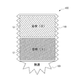
- FIG. 7 is a diagram schematically illustrating a heat storage device 10C according to the fourth modification.
- the heat-resistant frame 11B is a bellows-like expansion / contraction tube (bellows).
- the heat of the heat source 100 is absorbed from the heat absorption side heat storage unit 12 of the heat storage device 10C and radiated from the heat dissipation side heat storage unit 13
- the volume of the alloy (1) and the alloy (2) expands more than the solid state.
- the gas in the heat resistant frame 11B also expands by heating.
- the heat-resistant frame 11B can expand when the alloy or gas in the heat-resistant frame 11B expands in this way, the heat-resistant frame is damaged or the alloy leaks from the heat-resistant frame. Can be prevented.
- the heat-resistant frame 11 ⁇ / b> B is a bellows-like tubular tube (bellows), but is not limited to this, and any structure that can expand and contract may be used.
- the thermal energy conversion system according to the second embodiment of the present invention is a system that generates power using heat obtained from a heat source.
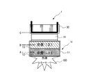
- FIG. 8 is a diagram schematically illustrating an example of the thermal energy conversion system 1 according to the embodiment of the present invention.
- the thermal energy conversion system 1 includes a heat storage device 10 that faces a heat source 100 that generates heat, a thermoelectric conversion module 20 that contacts the heat storage device 10 on the opposite side of the heat source 100, and a cooling device 30 that contacts the thermoelectric conversion module 20. Prepare.
- the thermal energy conversion system 1 which concerns on this embodiment is provided with the cooling device 30, the cooling device 30 is not an essential structure in this invention.
- the thermoelectric conversion module 20 includes a thermoelectric conversion layer 20 a and a pair of electrode layers 20 b sandwiching the thermoelectric conversion layer 20 a, one in contact with the heat storage device 10 and the other in contact with the cooling device 30.
- the thermoelectric conversion module 20 converts one heat of the electrode layer 20b into electric power using the Seebeck effect in which an electromotive force is generated in accordance with the temperature difference by forming one electrode layer 20b at a high temperature and the other at a low temperature to form a temperature difference. To do.
- thermoelectric conversion material constituting the thermoelectric conversion layer 20a for example, a silicon-germanium (SiGe) material is used for high temperature, and an oxide, clathrate, LAST (Ag, Pb, Sb, Te) is used for high temperature.
- SiGe silicon-germanium
- LAST Ag, Pb, Sb, Te
- Type oxide, clathrate, LAST (Ag, Pb, Sb, Te) materials
- TAGS Te, Ag, Ge, Sb type
- magnesium silicide (Mg 2 Si) type, PbTe type, Co—Sb type, Zn—Sb type, Mn—Si type materials for medium temperature use Bismuth-tellurium (Bi 2 Te 3 ) -based material is used for low temperature use.
- An insulating layer may be provided between the heat storage device 10 and the electrode layer 20b and between the cooling device 30 and the electrode layer 20b.
- the cooling device 30 includes a cooling pipe 30a through which a fluid or gas refrigerant (arrow in FIG. 8) flows, and the cooling pipe is brought into contact with the other electrode layer 20b of the thermoelectric conversion module 20 to flow through the cooling pipe 30a. Cool with the refrigerant.
- a known technique can be used for the cooling device 30.
- the cooling device 30 includes a cooling device including a refrigerant cooling heat exchanger disclosed in Japanese Patent Application Laid-Open No. 2008-159762, and a heat transfer tube through which a fluid flows as disclosed in Japanese Patent Application Laid-Open No. 2005-321156. Heat exchanger can be diverted.
- the contact thermal resistance between two solids depends on the surface roughness of each solid contact surface, the contact pressure between solids, and the like. Therefore, in order to improve the efficiency of heat transfer from the heat storage device 10 to the thermoelectric conversion module 20 and heat transfer from the thermoelectric conversion module 20 to the cooling device 30, the surface roughness of the contact surface is reduced or the contact pressure is reduced. It is preferable to enlarge it.
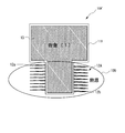
- FIG. 9 is a diagram schematically showing a thermal energy conversion system 1A according to a modification.
- the thermal energy conversion system 1A is different from the thermal energy conversion system 1 (see FIG. 8) in that an opening 16 is formed on the surface of the heat storage device 10D that faces the thermoelectric conversion module 20 of the heat resistant frame 11C.
- FIG. 10 is a photomicrograph of the metal structure of the 30Sn-70Zn alloy.
- each number given to the description of the 30Sn-70Zn alloy indicates the blending ratio in%. For example, if it is described as 30Sn-70Zn alloy, the Sn blending ratio is 30%. It indicates that the blending ratio of is 70%.
- the numbers attached to the description of the alloys have the same meaning.
- the alloy (2) maintains the temperature for a certain time when the temperature rises to the eutectic temperature, and then enters a solid-liquid coexistence state where the dendrite structure and the liquid phase coexist, and the dendrite structure seals the gap. And preventing excessive dissolution of the liquid phase.
- the liquid phase wets the electrode layer 20b and facilitates heat transfer between the alloy (2) and the electrode layer 20b.
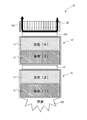
- FIG. 11 is a diagram schematically illustrating a thermal energy conversion system 1B according to a modification.
- the heat storage device 10 ′ and the thermoelectric conversion module 20A are further connected to the low temperature side of the thermoelectric conversion module 20 and then the cooling device 30 is connected. Different from FIG.
- the heat storage device 10 ′ is different from the heat storage device 10 (see FIG. 1) in that the heat absorption side heat storage unit 12 ′ is filled with the alloy (3) and the heat radiation side heat storage unit 13 ′ is filled with the alloy (4).
- the alloy (1) and the alloy (2), or the alloy (3) and the alloy (4) may be the same type of alloy or different types of alloys. Further, when the alloys (1) to (4) are different types of alloys, it is preferable that the eutectic temperature is higher in the order of the alloys (1) to (4) from the heat source 100 side.
- thermoelectric conversion module 20 has a thermoelectric conversion material for medium / high temperature (for example, Mg 2 Si-based material), and the thermoelectric conversion module 20A has a thermoelectric conversion material for low temperature (for example, Bi 2). Te 3 -based material) is preferable.
- the thermal energy conversion system according to Modification 3 includes a Stirling engine instead of the thermoelectric conversion module 20.
- the thermal energy conversion system according to Modification 3 is a system that operates a Stirling engine using heat obtained from a heat source as a heat source.
- the Stirling engine includes a cylinder and a piston that reciprocates within the cylinder.
- the heat storage device and the cooling device are brought into contact with the wall surface of the cylinder, and the piston is reciprocated by repeating the expansion and compression of the gas in the cylinder, thereby converting the thermal energy into kinetic energy. Convert.
- thermoelectric conversion module without providing a heat storage device, the high temperature side of the thermoelectric conversion module was heated, the cooling side was cooled, and the temperature change on the high temperature side and low temperature side over time and the open voltage of the thermoelectric conversion module were measured.
- the following modules were used as thermoelectric conversion modules.
- Module size 39.6 ⁇ 39.6 ⁇ 4.16 (mm)
- a low-carbon steel plate having a thickness of 10 m / m was disposed on the high temperature side of the thermoelectric conversion module, and a water-cooled low-carbon steel plate box was disposed on the low temperature side, and the low-carbon steel plate on the high temperature side was intermittently heated with a burner.
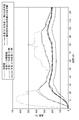
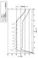
- FIG. 12 is a diagram illustrating a temperature change on the high temperature side and a low temperature side of the thermoelectric conversion module and a change in the open circuit voltage of the thermoelectric conversion module in the reference example.
- An alternate long and short dash line indicates a temperature change on the high temperature side of the thermoelectric conversion module.
- a two-dot chain line indicates a temperature change on the low temperature side of the thermoelectric conversion module.
- a solid line indicates a change in the open circuit voltage of the thermoelectric conversion module.
- thermocouple connected to a measuring device is provided at a predetermined location of the heat storage device of the embodiment, and the heat absorption side heat storage unit of the heat storage device is used as a heat source. It heated and the temperature change of the said predetermined location in progress of time was measured.
- the open voltage of the thermoelectric conversion module was measured in addition to the temperature change at a predetermined location of the thermal energy conversion system.
- FIG. 13 is a diagram illustrating a position where a thermocouple is provided in the heat storage device 10A ′ in the first embodiment.
- the thermocouple provided at the measurement location A (dotted line in FIG. 13) measures the temperature change at the center of the heat source.
- the thermocouple provided at the measurement location B (one-dot chain line in FIG. 13) measures the temperature change of the alloy (1) filled in the central portion of the tubular body 12a.
- the thermocouple provided at the measurement location C (two-dot chain line in FIG. 13) measures the temperature change of the alloy (1) filled in the vicinity of the heat resistant frame 11A of the tubular body 12a.
- a thermocouple provided at measurement point D (thick dotted line in FIG.
- thermocouple 13 measures a temperature change in the vicinity of heat-resistant frame 11A of the heat source.
- a thermocouple provided at measurement point E (thick one-dot chain line in FIG. 13) measures a temperature change on the heat source side of alloy (1) filled in the vicinity of tubular body 12a of heat-resistant frame 11A.
- the thermocouple provided at the measurement location F (thick two-dot chain line in FIG. 13) measures the temperature change of the alloy (1) filled in the central portion of the heat resistant frame 11A.
- the thermocouple provided at the measurement location G solid line in FIG. 13 measures the temperature change of the alloy (1) filled in the vicinity of the heat radiation side of the heat resistant frame 11A.
- the thermocouple provided at the measurement location H (broken line in FIG. 13) measures the temperature change on the heat radiation side of the heat resistant frame 11A.
- FIG. 14 is a diagram illustrating a temperature change at a predetermined location in the first embodiment. Each line in FIG. 14 shows the following.
- a dotted line shows the temperature change of the heat source center part measured in the measurement location A.
- a dashed-dotted line shows the temperature change of the alloy (1) with which the center part of the tubular body 12a measured in the measurement location B was filled.
- a two-dot chain line indicates a temperature change of the alloy (1) filled in the vicinity of the heat-resistant frame 11A of the tubular body 12a measured at the measurement location C.
- a thick dotted line indicates a temperature change in the vicinity of the heat-resistant frame 11A of the heat source measured at the measurement location D.
- a thick alternate long and short dash line indicates a temperature change of the alloy (1) filled in the vicinity of the tubular body 12a of the heat resistant frame 11A measured at the measurement location E.
- the thick two-dot chain line indicates the temperature change of the alloy (1) filled in the central portion of the heat resistant frame 11A measured at the measurement location F.
- the solid line shows the temperature change of the alloy (1) filled in the vicinity of the heat radiation side of the heat resistant frame 11A measured at the measurement location G.
- a broken line shows a temperature change on the heat radiation side of the heat resistant frame 11 ⁇ / b> A measured at the measurement location H.
- Example 1 a 50Sn-50Zn alloy was used as the alloy (1) and intermittently heated by a heat source. As shown in FIG. 14, by heating for about 60 minutes, the temperature of the heating part rose to 450 to 470 ° C., but the alloy (1) filled in the vicinity of the heat radiation side of the heat-resistant frame 11A is temporarily 250 to 470 ° C. The temperature rises to 270 ° C., but after that, it is maintained at a temperature in a certain range (around 199 ° C., which is the eutectic temperature of 50Sn-50Zn) for 50-60 minutes. Therefore, it has confirmed that the heat storage apparatus of this invention can store the heat of a fixed range temperature.
- FIG. 15 is a diagram showing positions where thermocouples are provided in the heat storage device or the thermal energy conversion system in Examples 2 to 9.
- the thermocouple provided at the measurement location A (dotted line in FIG. 15) measures the temperature change of the heating part heated by the burner.
- a thermocouple provided at measurement point B (a chain line in FIG. 15) measures a temperature change on the heat source side of alloy (1).
- a thermocouple provided at measurement location C (two-dot chain line in FIG. 15) measures the temperature change of alloy (1) on the alloy (2) side.
- a thermocouple provided at measurement point D (thick one-dot chain line in FIG. 15) measures a temperature change of alloy (2) on the alloy (1) side.
- the thermocouple provided at measurement point E (thick two-dot chain line in FIG.
- thermocouple 15 measures the temperature change of the alloy (2) on the side opposite to the alloy (1) side.
- the thermocouple provided at the measurement location F (broken line in FIG. 15) measures the temperature change on the opposite side of the heat-resistant frame 11 from the heating portion.
- the thermocouple provided at the measurement point G (thick dotted line in FIG. 15) measures the temperature change of the cooling part cooled by the refrigerant of the cooling device 30.
- FIGS. 16 to 23 are diagrams showing a change in temperature and a change in open circuit voltage at predetermined locations in each example, and each line in each figure shows the following.
- the dotted line shows the temperature change of the heating part measured at the measurement location A.
- a one-dot chain line shows a temperature change on the heat source side of the alloy (1) measured at the measurement point B.
- An alternate long and two short dashes line indicates a temperature change on the alloy (2) side of the alloy (1) measured at the measurement location C.
- a thick alternate long and short dash line indicates a temperature change on the alloy (1) side of the alloy (2) measured at the measurement point D.
- a thick two-dot chain line shows a temperature change on the opposite side to the alloy (1) side of the alloy (2) measured at the measurement point E.
- a broken line shows the temperature change on the opposite side to the heating part in the heat resistant frame 11 measured at the measurement location F.
- a thick dotted line shows the temperature change of the refrigerant of the cooling device 30 measured at the measurement point G.
- a solid line indicates a change in the open circuit voltage of the thermoelectric conversion module 20.
- Examples 2 to 7 are examples using the heat storage device 10 (see FIG. 1) according to the first embodiment.
- FIG. 16 is a diagram illustrating a temperature change at a predetermined location of the heat storage device 10 according to the second embodiment.
- Example 2 two spaces of 100 mm ⁇ 100 mm ⁇ 50 mm in the heat-resistant frame were filled with alloys (1) and (2), respectively, 15Al—85Zn alloy was used as alloy (1), and alloy (2) was used.
- a 30Sn-70Zn alloy was used and intermittently heated by a burner. As shown in FIG. 16, the temperature of the heating part rose to 500 to 600 ° C.
- the alloy (2) is maintained at a temperature within a certain range (around 199 ° C.) as the temperature rises to the eutectic temperature (199 ° C.) of the 30Sn—70Zn alloy. Further, the alloy (2) is kept at a temperature within a certain range (around 199 ° C.) for 20 to 30 minutes after the heating is stopped by turning off the burner. Therefore, it has confirmed that the heat storage apparatus of this invention can store the heat of a fixed range temperature.
- FIG. 17 is a diagram illustrating a temperature change at a predetermined location of the heat storage device 10 according to the third embodiment.
- Example 3 two spaces of 100 mm ⁇ 100 mm ⁇ 50 mm in the heat-resistant frame were filled with alloys (1) and (2), respectively, 15Al—85Zn alloy was used as alloy (1), and alloy (2) was used.
- a 30Sn-70Zn alloy was used and continuously heated by a burner.
- the alloy (2) has a temperature within a certain range (30Sn-70Zn alloy) for 30 to 40 minutes.
- the eutectic temperature is kept around 199 ° C.). Therefore, it has confirmed that the heat storage apparatus of this invention can store the heat of a fixed range temperature.
- FIG. 18 is a diagram illustrating a temperature change at a predetermined location of the heat storage device 10 according to the fourth embodiment.
- Example 4 two spaces of 100 mm ⁇ 100 mm ⁇ 50 mm in the heat-resistant frame were filled with alloys (1) and (2), respectively, and 86Al-11Si-3Cu alloy was used as alloy (1).
- 80Al-20Mg alloy was used and intermittently heated by a burner.
- the alloy (2) has a temperature within a certain range (80Al-20Mg alloy) for 30 to 40 minutes.
- the eutectic temperature is maintained at around 450 ° C.). Therefore, it has confirmed that the heat storage apparatus of this invention can store the heat of a fixed range temperature.
- FIG. 19 is a diagram illustrating a temperature change at a predetermined location of the heat storage device 10 according to the fifth embodiment.
- two spaces of 100 mm ⁇ 100 mm ⁇ 50 mm in the heat resistant frame were filled with alloys (1) and (2), respectively, 80Al-20Ni alloy was used as alloy (1), and alloy (2) was used.
- a 93Al-7Si alloy was used and intermittently heated by a burner.
- the heat storage apparatus of this invention can store the heat of a fixed range temperature.
- FIG. 20 is a diagram illustrating a temperature change at a predetermined location of the heat storage device 10 according to the sixth embodiment.
- Example 6 two spaces of 100 mm ⁇ 100 mm ⁇ 50 mm in the heat resistant frame were filled with the alloys (1) and (2), respectively, and 30Sn—70Zn alloy was used as the alloy (1) and the alloy (2). Intermittent heating with a burner. As shown in FIG. 20, the temperature of the heating part rose to 300 to 400 ° C.
- the alloy (2) is maintained at a temperature within a certain range (around 199 ° C.) as the temperature rises to the eutectic temperature (199 ° C.) of the 30Sn—70Zn alloy.
- the time during which the temperature is maintained within a certain range is short compared with Example 2, the alloy (2) is kept at a certain temperature (around 199 ° C.) for 10 to 15 minutes after the burner is turned off and heating is stopped. It is kept.
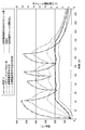
- FIG. 21 is a diagram illustrating a temperature change at a predetermined location of the thermal energy conversion system 1 and a change in the open voltage of the thermoelectric conversion module 20 according to the seventh embodiment.
- two spaces of 100 mm ⁇ 100 mm ⁇ 50 mm in the heat resistant frame were filled with alloys (1) and (2), respectively, and 15Al—85Zn alloy was used as alloy (1), and alloy (2) was used.
- a 30Sn-70Zn alloy was used and intermittently heated by a burner.
- the following modules were used as the thermoelectric conversion module 20.
- Thermoelectric element Bi-Te system (actual element size: approximately ⁇ 1.3 x 1.5 mm) 2. Number of elements: 254 (127 pairs) 3. Module size: 39.6 ⁇ 39.6 ⁇ 4.16 (mm)
- a heat transfer sheet graphite sheet
- grease manufactured by Toray Dow Corning: SC102 COMPOUND (thermal conductive material) was applied to the electrode on the cooling device 30 side of the thermoelectric conversion module 20.
- the alloy (2) has a certain range of temperatures (30Sn-70Zn). Since the open voltage of the thermoelectric conversion module 20 is maintained at around 2.5 V, the open voltage of the thermoelectric conversion module 20 follows the temperature of the alloy (2). I was able to confirm.
- FIG. 22 is a diagram illustrating a temperature change at a predetermined location of the thermal energy conversion system 1 and a change in the open voltage of the thermoelectric conversion module 20 according to the eighth embodiment.
- two spaces of 100 mm ⁇ 100 mm ⁇ 50 mm in the heat resistant frame were filled with the alloys (1) and (2), respectively, 80Al-20Ni alloy was used as the alloy (1), and the alloy (2) was used.
- a 93Al-7Si alloy was used and intermittently heated by a burner.
- the following modules were used as the thermoelectric conversion module 20.
- Product name Unileg type Mg 2 Si thermoelectric module Model number: Prototype Manufacturer name: Nippon Thermostat Co., Ltd. 1.
- Thermoelectric element Mg 2 Si (element size: 4 mm ⁇ ⁇ 10 mm) 2. Number of elements: 9 Module size: 28 x 28 x 12 (mm) Further, grease (manufactured by Toray Dow Corning: SC102 COMPOUND (thermal conductive material)) was applied to the electrode on the cooling device 30 side of the thermoelectric conversion module 20.
- the heating unit repeated heating over 600 to 700 ° C. three times.
- the alloy (2) Was maintained within a certain range of temperature (around 577 ° C., which is the eutectic temperature of 93Al-7Si), and it was confirmed that the open circuit voltage of the thermoelectric conversion module 20 was maintained at around 0.35V.
- the alloy (2) is kept at a certain temperature range (around 577 ° C.) for 30 minutes after the burner is turned off and the heating is stopped, and the open voltage of the thermoelectric conversion module 20 is maintained at around 0.35V. It could be confirmed.
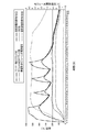
- FIG. 23 is a diagram illustrating a temperature change at a predetermined location of the thermal energy conversion system 1 and a change in the open voltage of the thermoelectric conversion module 20 according to the ninth embodiment.
- Example 9 two spaces of 60 mm ⁇ 60 mm ⁇ 15 mm in the heat resistant frame were filled with the alloys (1) and (2), respectively, 15Al—85Zn alloy was used as the alloy (1), and alloy (2) was used. A 30Sn-70Zn alloy was used and intermittently heated by a burner.
- Example 9 the same module as Example 7 was used as the thermoelectric conversion module 20.
- the alloy (2) has a temperature within a certain range (around 199 ° C., which is the eutectic temperature of 30Sn-70Zn) between about 5 minutes and about 55 minutes from the start of heating (0 minutes). Since the open voltage of the thermoelectric conversion module 20 is maintained at around 3.5 to 4.0 V, it was confirmed that the open voltage of the thermoelectric conversion module 20 follows the temperature of the alloy (2).
- Example 10 In Example 10, two spaces of 60 mm ⁇ 60 mm ⁇ 15 mm in the heat resistant frame were filled with the alloys (1) and (2), respectively, and 30Sn—70Zn alloy was used as the alloys (1) and (2). Was intermittently heated. In Example 10, the same module as Example 7 was used as the thermoelectric conversion module 20.
- FIG. 24 is a diagram illustrating a position where a thermocouple is provided in the thermal energy conversion system 1 in the tenth embodiment.
- a thermocouple provided at measurement point A (a chain line in FIG. 24) measures the temperature change of alloy (1).
- a thermocouple provided at measurement point B measures the temperature change of alloy (2).
- the thermocouple provided at the measurement location C (dotted line in FIG. 24) measures the temperature change of the cooling part cooled by the refrigerant of the cooling device 30.
- FIG. 25 is a diagram illustrating a temperature change at a predetermined location of the thermal energy conversion system 1 according to the tenth embodiment. Each line in FIG. 25 indicates the following.
- a dashed-dotted line shows the temperature change of the alloy (1) measured in the measurement location A.
- a two-dot chain line shows a temperature change of the alloy (2) measured at the measurement location B.
- a dotted line shows the temperature change of the cooling part cooled by the refrigerant
- FIG. A solid line indicates a change in the open circuit voltage of the thermoelectric conversion module 20.
- the alloy (2) is kept within a certain range of temperature (around 199 ° C., the eutectic temperature of 30Sn-70Zn). Since the open voltage of the thermoelectric conversion module 20 is maintained at around 2.5 V, it was confirmed that the open voltage of the thermoelectric conversion module 20 follows the temperature of the alloy (2).
- Example 9 and Example 10 the size of the heat-resistant frame is smaller than that in Example 7 and Example 8, and the amount of the filled alloy is about 1/10.
- the fluctuation is small, and as a result, the fluctuation of the open circuit voltage of the thermoelectric conversion module 20 is larger than that of the seventh and eighth embodiments. For this reason, it is preferable to apply such a small-sized thermal energy conversion system when the temperature variation of the heat source is small or when the installation size is limited. Further, if necessary, a plurality of heat resistant frames or thermal energy conversion systems may be combined, or a plurality of heat resistant frames or thermal energy conversion systems may be connected and used.
- Example 11 assuming that heat is absorbed from the atmosphere in the flue and converted into electric power, a thermal energy conversion system 110 as shown in FIG. 26 is configured. As shown in FIG. 26, the atmosphere is released upward by heating with a burner 130 from below the flue 120 of 650 mm ⁇ 850 mm. Inside the flue 120 is an endothermic Eroffin tube 140 (inner diameter ⁇ 27 mm, outer diameter ⁇ 65 mm), which is filled with a high temperature side 15Al-85Zn alloy. Further, heat storage frames 141A and 141B (70 mm ⁇ 70 mm ⁇ 100 mm) are connected to both ends of the erotic fin tube 140.
- Each of the heat storage frames 141A and 141B is divided into two spaces of a heat absorption side heat storage unit 142A and 142B and a heat dissipation side heat storage unit 143A and 143B, and the heat absorption side heat storage unit continuous with the erotic fin tube 140.
- 142A and 142B are filled with a 15Al-85Zn alloy on the high temperature side
- the heat radiation side heat storage parts 143A and 143B are filled with a 30Sn-70Zn alloy on the low temperature side.
- thermoelectric conversion module 150 is disposed on the heat dissipation side of the heat storage frame 141 ⁇ / b> A, and the cooling device 160 is further disposed on the low temperature side of the thermoelectric conversion module 150.
- 141 A of thermal storage frames, the thermoelectric conversion module 150, and the cooling device 160 were fixed with M10 volt
- Thermo module 150 the following modules were used.
- thermoelectric conversion module 150 39.6 ⁇ 39.6 ⁇ 4.16 (mm)
- a heat transfer sheet (graphite sheet) was sandwiched between the contact surfaces of the thermoelectric conversion module 150 and the heat storage frame 141A. Further, grease (manufactured by Toray Dow Corning: SC102 COMPOUND (thermal conductive material)) was applied to the electrode on the cooling device 160 side of the thermoelectric conversion module 150.
- thermocouple was provided at the measurement locations indicated by A to F in FIG.
- the measurement location A is a position 60 mm below the erotic fin tube 140 and measures the ambient temperature at the center of the flue 120.
- the measurement location B is for measuring the alloy temperature in the erotic fin tube 140.
- the measurement location C measures the alloy temperature in the heat absorption side heat storage part 142A.
- the measurement location D measures the alloy temperature of the part near the heat absorption side heat storage part 142A in the heat radiation side heat storage part 143A.
- the measurement location E measures the alloy temperature of the portion close to the thermoelectric conversion module 150 in the heat radiation side heat storage portion 143A.
- the measurement location F is for measuring the temperature of the cooling water flowing in the cooling device 160.
- FIG. 27 shows a change in temperature at each measurement point and a change in the open voltage of the thermoelectric conversion module 150 when the flue 120 in FIG. 26 is intermittently heated by the burner 130.
- the atmosphere temperature at the center of the flue 120 reached 550 ° C. in about 40 minutes to about 50 minutes from the start of heating (0 minutes), but the erotic fin tube 140 and the heat absorption side heat storage section 142A Since the alloy absorbs heat at the eutectoid temperature (275 ° C.) and the eutectic temperature (382 ° C.), the temperature rise of the alloy of the erotic fin tube 140 and the heat absorption side heat storage section 142A is moderate.
- thermoelectric conversion module 150 Even after heating is stopped after about 50 minutes, heat is generated at the eutectoid temperature (275 ° C.) and the eutectic temperature (382 ° C.), so the temperature of the alloy of the Erofine tube 140 and the heat absorption side heat storage section 142A decreases. Is no longer uniform. Even if intermittent heating is performed so that the ambient temperature in the center of the flue 120 is in the range of 200 to 550 ° C., the temperature of the alloy of the heat radiation side heat storage portion 143A is about 199 ° C., which is the eutectic temperature of 30Sn-70Zn. It was confirmed that the open voltage of the thermoelectric conversion module 150 was maintained at around 5V.
- thermoelectric conversion module 150 is maintained at around 5V for about 30 minutes after the heating is completely stopped. did it.
- Example 12 In Example 12, in order to confirm the effect of the thermal fuse, a thermal energy conversion system 170 as shown in FIG. 28 was configured. As shown in FIG. 28, the heat storage frame 180 (60 mm ⁇ 60 mm ⁇ 60 mm) is divided into two spaces, a heat absorption side heat storage unit 181 and a heat dissipation side heat storage unit 182, and the heat absorption side heat storage unit 181 includes Is filled with a 15Al-85Zn alloy on the high temperature side, and the heat dissipation side heat storage section 182 is filled with a 30Sn-70Zn alloy on the low temperature side.
- the heat absorption side heat storage unit 181 includes Is filled with a 15Al-85Zn alloy on the high temperature side
- the heat dissipation side heat storage section 182 is filled with a 30Sn-70Zn alloy on the low temperature side.
- a thermal fuse 190 is provided on the high temperature side of the heat storage frame 180 with a heat transfer sheet (graphite sheet) interposed therebetween.
- the thermal fuse 190 has a cylindrical shape and is housed in a refractory casing ( ⁇ 60 mm).
- the thermal fuse 190 includes a zinc soluble alloy 191 having a melting point of 419 ° C. which is lower than the melting point of 450 ° C. of the 15Al—85Zn alloy, and holding members 192A and 192B made of SS400 for holding the soluble alloy 191.
- the total thickness of the thermal fuse 190 is 30 mm, the thickness of the soluble alloy 191 is 6 mm, and the thickness of the holding members 192A and 192B is 12 mm.
- thermoelectric conversion module 200 is disposed on the heat radiation side of the heat storage frame 180 with a heat transfer sheet (graphite sheet) interposed therebetween, and the cooling device 210 is further disposed on the low temperature side of the thermoelectric conversion module 200.
- thermoelectric conversion module 200 the same module as in Example 11 was used.
- cooling device 210 a water-cooled heat sink (manufactured by Takagi Seisakusho: S-200W, oxygen-free copper, 80 mm ⁇ 80 mm ⁇ 19 mm, surface roughness 1.6a) was used.
- Grease Toray Dow Corning: SC102 COMPOUND (thermal conductive material) was applied to the electrode on the cooling device 210 side of the thermoelectric conversion module 200.
- thermocouple was provided at the measurement points indicated by A to F in FIG.
- the measurement location A is for measuring the temperature of the holding member 192A on the heat receiving side.
- the measurement location B is for measuring the temperature of the soluble alloy 191.
- Measurement location C measures the temperature of holding member 192B on the heat transfer side.
- the measurement point D is for measuring the alloy temperature of the portion close to the thermal fuse 190 in the heat absorption side heat storage unit 181.
- the measurement location E is for measuring the alloy temperature of the portion close to the thermoelectric conversion module 200 in the heat radiation side heat storage section 182.
- the measurement location F is for measuring the temperature of the cooling water flowing in the cooling device 210.
- FIG. 29 shows a change in temperature at each measurement point and a change in the open voltage of the thermoelectric conversion module 200 when the thermal fuse 190 in FIG. 28 is intermittently heated by a burner. As shown in FIG. 29, the heating with the burner is stopped twice before reaching the temperature at which the soluble alloy 191 of the thermal fuse 190 melts, and then continuously with the burner so as to be equal to or higher than the melting temperature of the soluble alloy 191. Heated.
- the temperature of the holding member 192A on the heat receiving side of the thermal fuse 190 rises, and as the surface in contact with the soluble alloy 191 becomes a temperature near the melting point of the soluble alloy 191, the soluble alloy 191 in the vicinity of the surface It gradually melts and finally falls by its own weight, and a gap is formed between the holding member 192A and the soluble alloy 191.
- heat transfer from the holding member 192A is deteriorated, the temperature of the soluble alloy 191 is lowered, and the melting of the soluble alloy 191 is once finished.
- the soluble alloy 191 reaches a temperature near the melting point, the same phenomenon as described above occurs, and the gap further increases.
- the gap between the holding member 192A and the soluble alloy 191 gradually increases.
- the temperature of the soluble alloy 191 is kept substantially constant at the melting temperature, and the temperature of the holding member 192B is also substantially constant.
- the constant temperature is transmitted to the heat storage frame 180. This confirms that it plays a role as a thermal fuse. It should be noted that the time from when the temperature of the soluble alloy 191 decreases and the melting of the soluble alloy 191 once ends to the next melting and the generation of a gap was initially the length of t1 in FIG. It turned out that it became long gradually with t2 and t3 as it repeated.
- Example 13 a thermal energy conversion system 220 as shown in FIG. 30 was configured in order to confirm the expansion / contraction action by using a bellows-like expansion / contraction tube (bellows) for the heat storage frame.
- a heat storage frame 230 ( ⁇ 120 mm ⁇ 120 mm) was constructed by welding flange plates to both ends of a heat-resistant bellows.
- a partition plate is provided in the center of the heat storage frame 230, and is divided into two spaces, a heat absorption side heat storage unit 231 and a heat dissipation side heat storage unit 232, and the heat absorption side heat storage unit 231 is filled with 20Sn-80Zn alloy.
- the heat radiation side heat storage section 232 is filled with 80Sn-20Zn alloy. Quartz glass plates 233A and 233B were integrally attached to the flange plate, and a quartz glass rod 234 was attached to the quartz glass plate 233A. Then, a change in the overall length of the heat storage frame 230 can be measured via a quartz glass rod 234 by a contact type digital sensor (manufactured by Keyence Corporation, sensor head GT2-H12, amplifier GT2-70MCN) (not shown).
- a contact type digital sensor manufactured by Keyence Corporation, sensor head GT2-H12, amplifier GT2-70MCN
- thermoelectric conversion module 240 is disposed on the heat radiation side of the heat storage frame 230 with a heat transfer sheet (graphite sheet) interposed therebetween, and a cooling device 250 is further disposed on the low temperature side of the thermoelectric conversion module 240.
- the cooling device 250 was pressed against the thermoelectric conversion module 240 by a compression coil spring with a pressing force of about 4 kgF.
- thermoelectric conversion module 240 the same module as in Example 11 was used.
- a water-cooled heat sink manufactured by Takagi Seisakusho: S-200W, oxygen-free copper, 80 mm ⁇ 80 mm ⁇ 19 mm, surface roughness 1.6a
- grease Toray Dow Corning: SC102 COMPOUND (thermal conductive material) was applied to the electrode on the cooling device 250 side of the thermoelectric conversion module 240.
- thermocouples were provided at the measurement points indicated by A to E in FIG.
- the measurement location A is for measuring the temperature of the flange plate on the burner side.
- the measurement location B measures the alloy temperature in the heat absorption side heat storage part 231.
- the measurement location C measures the alloy temperature in the heat radiation side heat storage section 232.
- the measurement location D is for measuring the temperature of the flange plate on the thermoelectric conversion module 240 side.
- the measurement location E is for measuring the temperature of the cooling water flowing through the cooling device 250.
- FIG. 31 shows a change in temperature at each measurement location when the heat energy conversion system 220 in FIG. 30 is intermittently heated by a burner, a change in the open voltage of the thermoelectric conversion module 240, and a change in the amount of elongation of the heat storage frame 230.
- the amount of elongation when the amount of elongation is a positive value, it means that the heat storage frame 230 has expanded, and when the amount of elongation is a negative value, it means that the heat storage frame 230 has contracted.
- no abnormalities such as leakage or damage of the alloy are observed in the heat storage frame 230 even after intermittent heating in the range of about 200 to about 500 ° C. after heating up to about 550 ° C. It was.
- thermoelectric conversion module 240 is 5 Stable at around 0.0V. It was confirmed that the heat storage frame 230 stretched by about 1 mm at the maximum as the temperature increased and contracted as the temperature decreased after the heating was stopped, and was synchronized with the heating cycle.
- Example 14 In Example 14, in order to confirm the influence by the kind of cooling device, the thermal energy conversion system 260 as shown in FIG. 32 was comprised.
- the cooling device 270 a water-cooled box made of SS400 steel plate with a black skin applied is used.
- the thermoelectric conversion module 240 is pressed by a compression coil spring with a pressing force of about 4 kgF. Pressed against. Since other configurations are the same as those of the thirteenth embodiment, the same reference numerals are given and detailed description thereof is omitted.
- FIG. 33 shows a change in temperature at each measurement point and a change in the open voltage of the thermoelectric conversion module 240 when the thermal energy conversion system 260 in FIG. 32 is intermittently heated by a burner.
- FIG. 33 shows a change in temperature at each measurement point and a change in the open voltage of the thermoelectric conversion module 240 when the thermal energy conversion system 260 in FIG. 32 is intermittently heated by a burner.
- FIG. 33 shows a change in temperature at each measurement point and a change in the open voltage of the thermoelectric conversion module 240 when the thermal energy conversion system 260 in FIG. 32 is intermittently heated by a burner.
- thermoelectric conversion module 240 Stable at 0 to 4.5V. Note that the open circuit voltage of the thermoelectric conversion module 240 is lower than that of Example 13 because the thermal resistance is higher when the cooling device 270 is used due to the difference in surface roughness and surface properties of the cooling device. It is estimated that it was high.
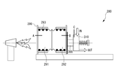
- Example 15 a thermal energy conversion system 280 as shown in FIG. 34 was configured in order to study another configuration using a bellows-like expansion / contraction tube (bellows) as a heat storage frame.
- a flange having a cylinder with an inner diameter equal to the outer diameter of the bellows was inserted into both ends of the heat-resistant bellows to constitute a heat storage frame 290 ( ⁇ 120 mm ⁇ 120 mm).
- a partition plate is provided in the center of the heat storage frame 290 and is divided into two spaces, a heat absorption side heat storage unit 291 and a heat dissipation side heat storage unit 292.
- the heat absorption side heat storage unit 291 is filled with 20Sn-80Zn alloy.
- the heat radiation side heat storage section 292 is filled with 80Sn-20Zn alloy. Further, in order to prevent the alloy from leaking from the gap between the flanges, a fireproof rope 293 ( ⁇ 9 isowool rope) was wound around the valley of the bellows for three valleys.
- thermoelectric conversion module 300 is disposed on the heat radiation side of the heat storage frame 290 with a heat transfer sheet (graphite sheet) interposed therebetween, and the cooling device 310 is further disposed on the low temperature side of the thermoelectric conversion module 300.
- the cooling device 310 was pressed against the thermoelectric conversion module 300 by a compression coil spring with a pressing force of about 4 kgF.
- thermoelectric conversion module 300 the same module as in Example 11 was used.
- a water-cooled heat sink manufactured by Takagi Seisakusho: S-200W, made of oxygen-free copper, 80 mm ⁇ 80 mm ⁇ 19 mm, surface roughness 1.6a
- Grease Toray Dow Corning: SC102 COMPOUND (thermal conductive material) was applied to the electrode on the cooling device 310 side of the thermoelectric conversion module 300.
- thermocouple was provided at the measurement points indicated by A to C in FIG.
- the measurement location A is for measuring the alloy temperature in the heat absorption side heat storage section 291.
- the measurement location B measures the alloy temperature in the heat radiation side heat storage section 292.
- the measurement location C is for measuring the temperature of the cooling water flowing in the cooling device 310.
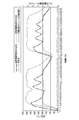
- FIG. 35 shows a change in temperature at each measurement point and a change in the open voltage of the thermoelectric conversion module 300 when the thermal energy conversion system 280 in FIG. 34 is intermittently heated by a burner.
- intermittent heating was repeated so that the melting temperature (380 ° C.) of the alloy in the heat absorption side heat storage section 291 was higher, but the heat storage frame 290 has abnormalities such as leakage and breakage of the alloy. I was not able to admit. Further, there is no influence on the heat storage effect by not welding the both ends of the bellows, and the temperature is kept near the eutectic temperature of the alloy in the heat-radiation side heat storage section 292.
- the open voltage of the thermoelectric conversion module 300 is 6.0 to Stable at 6.5V.
- the elongation of the heat storage frame 290 accompanying the temperature rise was one pile (about 5 mm) of the bellows.
- thermoelectric conversion module 20a thermoelectric conversion layer, 20b electrode layer, 25 gap, 30 cooling device, 100 heat source, 110 thermal energy conversion System, 120 flue, 130 burner, 140 erotic fin tube, 141A, 141B heat storage frame, 142A, 142B heat absorption side heat storage unit, 143A, 143B heat dissipation side heat storage unit, 150 thermoelectric conversion module, 160 cooling device, 170 heat energy Conversion system 180 heat storage frame, 181 heat absorption side heat storage unit, 182 heat radiation side heat storage unit, 190 temperature fuse, 191 soluble alloy, 192A, 192B holding member, 200 thermoelectric conversion module, 210 cooling device, 220
Landscapes
- Engineering & Computer Science (AREA)
- Chemical & Material Sciences (AREA)
- Physics & Mathematics (AREA)
- Thermal Sciences (AREA)
- Combustion & Propulsion (AREA)
- Chemical Kinetics & Catalysis (AREA)
- Materials Engineering (AREA)
- Organic Chemistry (AREA)
- Mechanical Engineering (AREA)
- General Engineering & Computer Science (AREA)
- Cooling Or The Like Of Electrical Apparatus (AREA)
- Cooling Or The Like Of Semiconductors Or Solid State Devices (AREA)
Abstract
一定温度範囲の熱を蓄えて安定に蓄熱可能な蓄熱装置を提供する。 本発明に係る蓄熱装置10は、所定の共晶温度を有する1種の合金又は混合塩を充填した耐熱性枠体11、あるいは共晶温度が異なる2種以上の合金又は混合塩を共晶温度の高さの順に隔壁11aを介して隣接させて充填した耐熱性枠体11を備え、所定の共晶温度を有する1種の合金又は混合塩を充填した耐熱性枠体11を吸熱側蓄熱部12及び放熱側蓄熱部13とし、又は合金又は混合塩が2種以上の場合、共晶温度が最も高い合金(1)又は混合塩(1)を充填した耐熱性枠体11を吸熱側蓄熱部12とし、共晶温度が最も低い合金(2)又は混合塩(2)を充填した耐熱性枠体11を放熱側蓄熱部13とすることを特徴とする。
Description
本発明は、所定の共晶温度を有する合金又は混合塩を備えた蓄熱装置及び当該蓄熱装置を備えるシステムに関する。
近年、環境問題の高まりに応じて、工場等における生産設備、発電所、自動車等から生ずる排熱は、熱エネルギーとして効率的に利用する様々な手段が検討されている。このような排熱は、新たなエネルギーに変換されて利用される。
排熱を新たなエネルギーに変換する装置として、例えば、特許文献1には、熱から発電する2つの熱電変換モジュールの間に所定の温度に設定される温度設定層を設けた熱処理装置が示されている。また、特許文献2には、高温側と低温側の発電素子の間に熱流を制御可能な中間熱伝達ループを設けた熱電発電システムが示されている。
しかしながら、工場等における生産設備、発電所、自動車等から生ずる排熱は温度の上昇と下降が激しいために、温度が安定して生ずるものではないため、この排熱を利用して得られるエネルギーも安定して供給できないという問題がある。
このような温度の激しく上昇する排熱は、熱電変換モジュールやスターリングエンジン等のエネルギー変換装置の熱源として利用しても、エネルギー変換装置が壊れてしまう問題が生ずる。
このような温度の激しく上昇する排熱は、熱電変換モジュールやスターリングエンジン等のエネルギー変換装置の熱源として利用しても、エネルギー変換装置が壊れてしまう問題が生ずる。
ところで、共晶反応を有する合金又は混合塩は、加熱すると温度が上昇し、加熱を止めると温度が降下するが、共晶点近傍では温度変化が緩やかになる。このような合金又は混合塩を用いた蓄熱装置を、排熱が発生する熱源と、例えば熱電変換モジュール等のエネルギー変換装置との間に設けることができれば、共晶点近傍の一定温度範囲の熱を、安定してエネルギー変換装置に供給できる。
本発明は、以上の課題に鑑みてなされたものであり、一定温度範囲の熱を蓄えて安定に蓄熱可能な蓄熱装置を提供することを目的とする。
また、本発明は、前記蓄熱装置から放出される一定温度範囲の熱によって、前記エネルギー変換装置を安定に稼動させるシステムを提供することを目的とする。
更に、本発明は、前記エネルギー変換装置が熱電変換モジュールの場合、前記蓄熱装置から放出される一定温度範囲の熱によって一定の発電量を維持できる発電システムを提供することを目的とする。
また、本発明は、前記蓄熱装置から放出される一定温度範囲の熱によって、前記エネルギー変換装置を安定に稼動させるシステムを提供することを目的とする。
更に、本発明は、前記エネルギー変換装置が熱電変換モジュールの場合、前記蓄熱装置から放出される一定温度範囲の熱によって一定の発電量を維持できる発電システムを提供することを目的とする。
(1) 所定の共晶温度を有する1種の合金又は混合塩を充填した耐熱性枠体、あるいは共晶温度が異なる2種以上の合金又は混合塩を共晶温度の高さの順に隔壁を介して隣接させて充填した耐熱性枠体を備えることを特徴とする蓄熱装置。
(2) 所定の共晶温度を有する1種の合金又は混合塩を充填した耐熱性枠体を吸熱部及び放熱部とすることを特徴とする(1)に記載の蓄熱装置。
(3) 合金又は混合塩が2種以上の場合、共晶温度が最も高い合金(1)又は混合塩(1)を充填した耐熱性枠体を吸熱部とし、共晶温度が最も低い合金(2)又は混合塩(2)を充填した耐熱性枠体を放熱部とすることを特徴とする(1)に記載の蓄熱装置。
(4) 集熱部品を備える(1)乃至(3)のいずれかに記載の蓄熱装置。
(5) 前記耐熱性枠体が伸縮可能な構造である(1)乃至(4)のいずれかに記載の蓄熱装置。
(6) (2)に記載の蓄熱装置と、前記放熱部に接続されるエネルギー変換装置と、を備えることを特徴とするシステム。
(7) (3)に記載の蓄熱装置と、前記放熱部に接続されるエネルギー変換装置と、を備えることを特徴とするシステム。
(8) 前記エネルギー変換装置が熱電変換モジュールであることを特徴とする(6)又は(7)に記載のシステム。
(9) 前記エネルギー変換装置がスターリングエンジンであることを特徴とする(6)又は(7)に記載のシステム。
(10) 温度ヒューズ及び/又は冷却部を備える(6)乃至(9)のいずれかに記載のシステム。
(11) (8)に記載のシステムを用い、前記吸熱部において吸熱することによって蓄熱し、前記放熱部から放出される熱を熱源にして前記熱電変換モジュールで発電させる方法。
(12) (9)に記載のシステムを用い、前記吸熱部において吸熱することによって蓄熱し、前記放熱部から放出される熱を熱源にしてスターリングエンジンを稼動させる方法。
本発明によれば、一定温度範囲の熱を蓄えて安定に蓄熱可能な蓄熱装置を提供することができる。
また、本発明によれば、前記蓄熱装置から放出される一定温度範囲の熱によって、前記エネルギー変換装置を安定に稼動させるシステムを提供できる。
更に、本発明によれば、前記エネルギー変換装置が熱電変換モジュールの場合、前記蓄熱装置から放出される一定温度範囲の熱によって一定の発電量を維持できる発電システムを提供できる。
また、本発明によれば、前記蓄熱装置から放出される一定温度範囲の熱によって、前記エネルギー変換装置を安定に稼動させるシステムを提供できる。
更に、本発明によれば、前記エネルギー変換装置が熱電変換モジュールの場合、前記蓄熱装置から放出される一定温度範囲の熱によって一定の発電量を維持できる発電システムを提供できる。
以下に、本発明の実施形態を図面に基づいて詳細に説明する。なお、以下の実施形態の説明にあたって、同一構成については同一符号を付し、その説明を省略もしくは簡略化する。
《第1実施形態》
本発明の蓄熱装置は、熱源から得た温度が不安定な熱を潜熱により蓄積する装置である。
本発明の蓄熱装置は、所定の共晶温度を有する合金又は混合塩で蓄熱し、この合金又は混合塩は1種類でもよいし複数種類でもよい。
以下に説明する本発明の第1実施形態に係る蓄熱装置10は、本発明の蓄熱装置の一例として、2種類の合金を用いたものである。
図1は、本発明の実施形態に係る蓄熱装置10の一例を模式的に示す図である。
本発明の蓄熱装置は、熱源から得た温度が不安定な熱を潜熱により蓄積する装置である。
本発明の蓄熱装置は、所定の共晶温度を有する合金又は混合塩で蓄熱し、この合金又は混合塩は1種類でもよいし複数種類でもよい。
以下に説明する本発明の第1実施形態に係る蓄熱装置10は、本発明の蓄熱装置の一例として、2種類の合金を用いたものである。
図1は、本発明の実施形態に係る蓄熱装置10の一例を模式的に示す図である。
蓄熱装置10は、箱状の耐熱性枠体11と、熱源100側の耐熱性枠体11の内部に合金(1)が充填されて形成される吸熱側蓄熱部12と、吸熱側蓄熱部12と耐熱性枠体11の隔壁11aを介して隣接し、耐熱性枠体11の内部に合金(2)が充填されて形成される放熱側蓄熱部13と、を備える。
<蓄熱装置10の構成>
[耐熱性枠体]
耐熱性枠体11は、箱状体であり、内部に所定の容量の空間を有する。耐熱性枠体11は、奥行き方向において耐熱性枠体11の内部を2等分にする隔壁11aを有する。すなわち、耐熱性枠体11は、隔壁11aを介して隣接する所定の容量の空間を2つ有する。なお、本実施形態に係る耐熱性枠体11は箱状体に形成しているが、本発明においては箱状体に限らず、管状体等の合金を充填可能な形状とすることができる。また、本実施形態に係る耐熱性枠体11は内部を2等分にしているが、本発明においては2等分に限らず、充填する合金の特性等に応じた容積比で分けることができる。また、合金(1)及び合金(2)が同種の合金である場合は、隔壁11aを設けないこともできる。この場合、耐熱性枠体11は、1つの空間を有することとなる。
更に、耐熱性枠体11は、放熱側蓄熱部13における吸熱側蓄熱部12と接する面とは反対側の面を、吸熱側蓄熱部12と接する面より広くすることもできる。これにより、例えば、蓄熱装置10を熱電変換モジュールに接続する場合、1つの蓄熱装置10に複数の熱電変換モジュールに接続することができる。
[耐熱性枠体]
耐熱性枠体11は、箱状体であり、内部に所定の容量の空間を有する。耐熱性枠体11は、奥行き方向において耐熱性枠体11の内部を2等分にする隔壁11aを有する。すなわち、耐熱性枠体11は、隔壁11aを介して隣接する所定の容量の空間を2つ有する。なお、本実施形態に係る耐熱性枠体11は箱状体に形成しているが、本発明においては箱状体に限らず、管状体等の合金を充填可能な形状とすることができる。また、本実施形態に係る耐熱性枠体11は内部を2等分にしているが、本発明においては2等分に限らず、充填する合金の特性等に応じた容積比で分けることができる。また、合金(1)及び合金(2)が同種の合金である場合は、隔壁11aを設けないこともできる。この場合、耐熱性枠体11は、1つの空間を有することとなる。
更に、耐熱性枠体11は、放熱側蓄熱部13における吸熱側蓄熱部12と接する面とは反対側の面を、吸熱側蓄熱部12と接する面より広くすることもできる。これにより、例えば、蓄熱装置10を熱電変換モジュールに接続する場合、1つの蓄熱装置10に複数の熱電変換モジュールに接続することができる。
また、耐熱性枠体11は、所定の厚さの耐熱材(例えば、SS、SUS、SCH、SCS等)で形成されている。
耐熱性枠体11は、2つの空間を形成し1面が開放された箱部と、箱部の開放された1面を塞ぐ蓋部とを備える。
耐熱性枠体11は、2つの空間を形成し1面が開放された箱部と、箱部の開放された1面を塞ぐ蓋部とを備える。
吸熱側蓄熱部12は、耐熱性枠体11の2つの空間のうち熱源100側の空間に合金(1)が充填されて形成されている。
放熱側蓄熱部13は、耐熱性枠体11の2つの空間のうち熱源100側の反対側の空間に合金(2)が充填されて形成されている。
本実施形態において、吸熱側蓄熱部12及び放熱側蓄熱部13は、直接耐熱性枠体11に合金(1)又は合金(2)が充填されているが、本発明はこれに限定されず、吸熱側蓄熱部12及び放熱側蓄熱部13は、それぞれ個別の枠体を備え、この枠体に合金(1)又は合金(2)が充填され、合金(1)又は合金(2)が充填された枠体を、耐熱性枠体11と着脱自在に設けることもできる。
放熱側蓄熱部13は、耐熱性枠体11の2つの空間のうち熱源100側の反対側の空間に合金(2)が充填されて形成されている。
本実施形態において、吸熱側蓄熱部12及び放熱側蓄熱部13は、直接耐熱性枠体11に合金(1)又は合金(2)が充填されているが、本発明はこれに限定されず、吸熱側蓄熱部12及び放熱側蓄熱部13は、それぞれ個別の枠体を備え、この枠体に合金(1)又は合金(2)が充填され、合金(1)又は合金(2)が充填された枠体を、耐熱性枠体11と着脱自在に設けることもできる。
[合金]
吸熱側蓄熱部12の合金(1)の共晶温度は、放熱側蓄熱部13の合金(2)の共晶温度より高い。
合金(1)は、熱源100により発生する熱の温度及び熱量の変動を吸収し、所定の温度範囲の熱を合金(2)に供給する。
合金(2)は、合金(1)から供給された熱の温度変化を吸収し、所定の温度範囲の熱を蓄熱する。
吸熱側蓄熱部12の合金(1)の共晶温度は、放熱側蓄熱部13の合金(2)の共晶温度より高い。
合金(1)は、熱源100により発生する熱の温度及び熱量の変動を吸収し、所定の温度範囲の熱を合金(2)に供給する。
合金(2)は、合金(1)から供給された熱の温度変化を吸収し、所定の温度範囲の熱を蓄熱する。
合金(1)及び合金(2)は、所定の共晶温度を有する合金であり、熱源100により発生する熱の温度範囲に、共晶温度が含まれる合金が選択される。
例えば、熱源100により発生する熱の温度範囲が図2中のT1からT2の範囲であり、蓄熱装置10に接続される熱電変換モジュールの無次元性能指数ZTが温度変化に伴って図2中に示されるように変化する場合、合金(1)としては、共晶温度が図2中のT3からT4の範囲であるものを選択することが好ましく、合金(2)としては、共晶温度が図2中のT5からT6の範囲であるものを選択することが好ましい。このように合金(1)及び合金(2)を選択することにより、無次元性能指数ZTが最も高くなるような温度範囲の熱を熱電変換モジュールに伝達することができる。
例えば、熱源100により発生する熱の温度範囲が図2中のT1からT2の範囲であり、蓄熱装置10に接続される熱電変換モジュールの無次元性能指数ZTが温度変化に伴って図2中に示されるように変化する場合、合金(1)としては、共晶温度が図2中のT3からT4の範囲であるものを選択することが好ましく、合金(2)としては、共晶温度が図2中のT5からT6の範囲であるものを選択することが好ましい。このように合金(1)及び合金(2)を選択することにより、無次元性能指数ZTが最も高くなるような温度範囲の熱を熱電変換モジュールに伝達することができる。
図3は、本実施形態に係る合金の一例であるSn-Zn合金の状態図を示している。
図3に示すように、本実施形態に係る合金の一例であるSn-Zn合金の共晶温度は、199℃である。
合金は、例えば、Sn-Zn合金の様に共晶温度が199℃である場合、合金の温度を199℃より高く加熱する場合には熱を吸熱し、199℃より低く冷却する場合には熱を放熱する。
図3に示すように、本実施形態に係る合金の一例であるSn-Zn合金の共晶温度は、199℃である。
合金は、例えば、Sn-Zn合金の様に共晶温度が199℃である場合、合金の温度を199℃より高く加熱する場合には熱を吸熱し、199℃より低く冷却する場合には熱を放熱する。
合金による吸熱量及び発熱量は、合金の熱容量(比熱×比重×容積)+融解エンタルピーを変化させることで、調整可能となる。例えば、吸熱量及び発熱量をより大きくしたい場合には、比重や融解エンタルピーがより大きい金属で合金を組成したり、容積をより大きくしたりすることで、合金の吸熱量及び発熱量をより大きくできる。
本実施形態において、吸熱側蓄熱部12及び放熱側蓄熱部13の合金を、それぞれ異なるものとしているが、本発明はこれに限定されず、吸熱側蓄熱部12及び放熱側蓄熱部13の合金を同じものとすることもできる。この場合、耐熱性枠体11の隔壁11aを設けず、耐熱性枠体11の空間を1つにすることもできる。
また、本実施形態において、耐熱性枠体11の内部の空間を2等分にし、この2つの空間に2種類の合金を充填しているが、本発明はこれに限定されず、耐熱性枠体11の内部の空間を3以上の空間に分割し、これらの空間にそれぞれ異なる合金を充填することもできる。この場合、合金は、熱源100側から、共晶温度が高い順に充填される。
また、本実施形態において、吸熱側蓄熱部12及び放熱側蓄熱部13には合金を充填しているが、本発明はこれに限定されず、吸熱側蓄熱部12及び放熱側蓄熱部13に混合塩を充填することができる。
(合金及び混合塩の具体例)
合金及び混合塩の具体例を以下に示す。
表1は、低温用の合金(1)及び合金(2)の具体例である。低温用とは、熱源100より発生される熱の温度が最大400℃までの場合に用いられる合金である。
表2は、表1に示した合金以外の低温用の合金及び低温用の混合塩の具体例である。

合金及び混合塩の具体例を以下に示す。
表1は、低温用の合金(1)及び合金(2)の具体例である。低温用とは、熱源100より発生される熱の温度が最大400℃までの場合に用いられる合金である。
表2は、表1に示した合金以外の低温用の合金及び低温用の混合塩の具体例である。

表3は、中温用の合金(1)及び合金(2)の具体例である。中温用とは、熱源100より発生される熱の温度が最大800℃までの場合に用いられる合金である。
表4は、表3に示した合金以外の中温用の合金及び中温用の混合塩の具体例である。

表4は、表3に示した合金以外の中温用の合金及び中温用の混合塩の具体例である。

表5は、高温用の合金(1)及び合金(2)の具体例である。高温用とは、熱源100より発生される熱の温度が最大1000℃までの場合に用いられる合金である。
表6は、表5に示した合金以外の高温用の合金の具体例である。

表6は、表5に示した合金以外の高温用の合金の具体例である。

<蓄熱装置10の製造方法>
蓄熱装置10の製造方法について説明する。
まず、吸熱側蓄熱部12及び放熱側蓄熱部13を形成する2つの空間を有する耐熱性枠体11を箱部と蓋部とに分けて製作する。
次に、熱源100で発生する熱の温度範囲に応じて、合金(1)及び合金(2)の合金の種類を選択する。
合金(1)を組成する2種類の単体金属を所定の重量比で配合し、るつぼ炉にて加熱することで溶解し、箱部における吸熱側蓄熱部12を形成する空間に注湯する。また、合金(2)を組成する2種類の単体金属を所定の重量比で配合し、るつぼ炉にて加熱することで溶解し、箱部における放熱側蓄熱部13を形成する空間に注湯する。
次に、箱部に蓋部を取り付ける。
なお、更に、熱損失を防ぐため、蓄熱装置10に断熱材を巻き付ける場合もある。
蓄熱装置10の製造方法について説明する。
まず、吸熱側蓄熱部12及び放熱側蓄熱部13を形成する2つの空間を有する耐熱性枠体11を箱部と蓋部とに分けて製作する。
次に、熱源100で発生する熱の温度範囲に応じて、合金(1)及び合金(2)の合金の種類を選択する。
合金(1)を組成する2種類の単体金属を所定の重量比で配合し、るつぼ炉にて加熱することで溶解し、箱部における吸熱側蓄熱部12を形成する空間に注湯する。また、合金(2)を組成する2種類の単体金属を所定の重量比で配合し、るつぼ炉にて加熱することで溶解し、箱部における放熱側蓄熱部13を形成する空間に注湯する。
次に、箱部に蓋部を取り付ける。
なお、更に、熱損失を防ぐため、蓄熱装置10に断熱材を巻き付ける場合もある。
<蓄熱装置10における熱伝達のメカニズム>
熱源100において熱が発生していない状態では、吸熱側蓄熱部12の合金(1)及び放熱側蓄熱部13の合金(2)は、固体状態である。
熱源100において熱が発生すると、まず、合金(1)の温度が上昇する。合金(1)は、共晶温度まで温度が上昇すると一定時間その温度を保ち、その後固液共存状態となり、温度の上昇が緩やかとなる。
この合金(1)の熱は、合金(2)に伝達される。合金(2)は、共晶温度まで温度が上昇すると一定時間その温度を保ち、その後固液共存状態となり、温度の上昇が緩やかとなる。
蓄熱装置10に熱電変換モジュールを取り付けた場合には、この合金(2)の熱は、熱電変換モジュールに伝達される。
なお、蓄熱装置10は、共晶温度付近における吸熱/発熱反応により、熱の温度変動を吸収することができるが、合金(1)及び/又は合金(2)が共晶反応及び共析反応を有する場合には、共析温度付近における吸熱/発熱反応によっても、熱の温度変動を吸収することができる。
熱源100において熱が発生していない状態では、吸熱側蓄熱部12の合金(1)及び放熱側蓄熱部13の合金(2)は、固体状態である。
熱源100において熱が発生すると、まず、合金(1)の温度が上昇する。合金(1)は、共晶温度まで温度が上昇すると一定時間その温度を保ち、その後固液共存状態となり、温度の上昇が緩やかとなる。
この合金(1)の熱は、合金(2)に伝達される。合金(2)は、共晶温度まで温度が上昇すると一定時間その温度を保ち、その後固液共存状態となり、温度の上昇が緩やかとなる。
蓄熱装置10に熱電変換モジュールを取り付けた場合には、この合金(2)の熱は、熱電変換モジュールに伝達される。
なお、蓄熱装置10は、共晶温度付近における吸熱/発熱反応により、熱の温度変動を吸収することができるが、合金(1)及び/又は合金(2)が共晶反応及び共析反応を有する場合には、共析温度付近における吸熱/発熱反応によっても、熱の温度変動を吸収することができる。
<蓄熱装置の変形例1>
次に、蓄熱装置の変形例1について説明する。
図4は、変形例1に係る蓄熱装置10Aを模式的に示す図である。
蓄熱装置10Aは、吸熱側蓄熱部12Aに集熱部品12bが設けられている。蓄熱装置10Aにおける合金(1)と合金(2)の容積比は略3:7である。
吸熱側蓄熱部12Aは、耐熱性枠体11の隔壁11aにより分けられた2つの空間のうち熱源100側の空間に合金(1)が充填された部分と、合金(1)が充填された管状体12aと、管状体12aの外周に螺旋状に形成された集熱部品12bと、を備える。
集熱部品12bは、気体や液体の熱を吸熱する部品であり、気体と接する面積を増加させるフィンである。集熱部品12bで吸熱された熱は、管状体12aに伝達され、管状体12aに充填された合金(1)に吸熱される。集熱部品12bを設けることで、気体や液体から熱を吸熱する場合に、吸熱の効率を向上できる。
なお、図4には、集熱部品12bの具体的な一態様としてフィンを示しているが、集熱部品12bの態様はフィンに限定されず、例えば、ジャバラ状の管状体とすることもできる。
次に、蓄熱装置の変形例1について説明する。
図4は、変形例1に係る蓄熱装置10Aを模式的に示す図である。
蓄熱装置10Aは、吸熱側蓄熱部12Aに集熱部品12bが設けられている。蓄熱装置10Aにおける合金(1)と合金(2)の容積比は略3:7である。
吸熱側蓄熱部12Aは、耐熱性枠体11の隔壁11aにより分けられた2つの空間のうち熱源100側の空間に合金(1)が充填された部分と、合金(1)が充填された管状体12aと、管状体12aの外周に螺旋状に形成された集熱部品12bと、を備える。
集熱部品12bは、気体や液体の熱を吸熱する部品であり、気体と接する面積を増加させるフィンである。集熱部品12bで吸熱された熱は、管状体12aに伝達され、管状体12aに充填された合金(1)に吸熱される。集熱部品12bを設けることで、気体や液体から熱を吸熱する場合に、吸熱の効率を向上できる。
なお、図4には、集熱部品12bの具体的な一態様としてフィンを示しているが、集熱部品12bの態様はフィンに限定されず、例えば、ジャバラ状の管状体とすることもできる。
<蓄熱装置の変形例2>
次に、蓄熱装置の変形例2について説明する。
図5は、変形例2に係る蓄熱装置10A’を模式的に示す図である。
変形例2は、耐熱性枠体に隔壁が設けられておらず、耐熱性枠体の空間及び管状体に1種類の合金が充填されている点が、変形例1と異なる。
蓄熱装置10A’は、1つの空間を有する耐熱性枠体11Aと、管状体12aと、管状体12aの外周に螺旋状に形成された集熱部品12bと、を備え、耐熱性枠体11Aの空間及び管状体12aに同一種類の合金(1)が充填されている。
次に、蓄熱装置の変形例2について説明する。
図5は、変形例2に係る蓄熱装置10A’を模式的に示す図である。
変形例2は、耐熱性枠体に隔壁が設けられておらず、耐熱性枠体の空間及び管状体に1種類の合金が充填されている点が、変形例1と異なる。
蓄熱装置10A’は、1つの空間を有する耐熱性枠体11Aと、管状体12aと、管状体12aの外周に螺旋状に形成された集熱部品12bと、を備え、耐熱性枠体11Aの空間及び管状体12aに同一種類の合金(1)が充填されている。
<蓄熱装置の変形例3>
次に、蓄熱装置の変形例3について説明する。
図6は、変形例3に係る蓄熱装置10Bを模式的に示す図である。
蓄熱装置10Bは、吸熱側蓄熱部12の熱源100側に温度ヒューズ15が設けられている。蓄熱装置10Bにおける合金(1)と合金(2)の容積比は略4:6である。
温度ヒューズ15は、所定の温度で溶解する可溶性合金15aと、可溶性合金15aを保持する保持部材15bと、を備える。
可溶性合金15aは、合金(1)で吸熱可能な温度近傍で溶解する合金で形成されている。可溶性合金15aの融点は、合金(1)の共晶温度よりも高く、合金(1)の融点よりも低ければよい。
保持部材15bは、少なくとも高温用(最大1000℃)の合金(1)より融点が高い、例えば、銅等により形成されている。
温度ヒューズ15は、熱源100から発生した熱の温度が合金(1)で吸熱可能な温度のときは、熱を吸熱し合金(1)にこの熱を伝達し、熱源100から発生した熱の温度が合金(1)で吸熱可能な温度を超えたときには、可溶性合金15aが溶解し、熱が合金(1)に伝達するのを防止する。
図6に示す蓄熱装置10Bでは、蓄熱装置10と熱源100との間に温度ヒューズ15を設けたが、蓄熱装置10に熱電変換モジュールを接続する場合、この温度ヒューズ15は、蓄熱装置10と熱電変換モジュールとの間に設けることもできる。
次に、蓄熱装置の変形例3について説明する。
図6は、変形例3に係る蓄熱装置10Bを模式的に示す図である。
蓄熱装置10Bは、吸熱側蓄熱部12の熱源100側に温度ヒューズ15が設けられている。蓄熱装置10Bにおける合金(1)と合金(2)の容積比は略4:6である。
温度ヒューズ15は、所定の温度で溶解する可溶性合金15aと、可溶性合金15aを保持する保持部材15bと、を備える。
可溶性合金15aは、合金(1)で吸熱可能な温度近傍で溶解する合金で形成されている。可溶性合金15aの融点は、合金(1)の共晶温度よりも高く、合金(1)の融点よりも低ければよい。
保持部材15bは、少なくとも高温用(最大1000℃)の合金(1)より融点が高い、例えば、銅等により形成されている。
温度ヒューズ15は、熱源100から発生した熱の温度が合金(1)で吸熱可能な温度のときは、熱を吸熱し合金(1)にこの熱を伝達し、熱源100から発生した熱の温度が合金(1)で吸熱可能な温度を超えたときには、可溶性合金15aが溶解し、熱が合金(1)に伝達するのを防止する。
図6に示す蓄熱装置10Bでは、蓄熱装置10と熱源100との間に温度ヒューズ15を設けたが、蓄熱装置10に熱電変換モジュールを接続する場合、この温度ヒューズ15は、蓄熱装置10と熱電変換モジュールとの間に設けることもできる。
<蓄熱装置の変形例4>
次に、蓄熱装置の変形例4について説明する。
図7は、変形例4に係る蓄熱装置10Cを模式的に示す図である。
蓄熱装置10Cは、耐熱性枠体11Bがジャバラ状の伸縮管(ベローズ)となっている。熱源100の熱を蓄熱装置10Cの吸熱側蓄熱部12から吸熱し、放熱側蓄熱部13から放熱する場合、合金(1)及び合金(2)の体積は固体状態よりも膨張する。また、耐熱性枠体11B内の気体も加熱により膨張する。耐熱性枠体11Bは、このように耐熱性枠体11B内の合金や気体が膨張した場合に伸長することができるため、耐熱性枠体が破損したり耐熱性枠体から合金が漏れ出たりすることを防ぐことができる。
なお、図7では、耐熱性枠体11Bをジャバラ状の管状管(ベローズ)としたが、これに限定されるものではなく、伸縮可能な構造であればよい。
次に、蓄熱装置の変形例4について説明する。
図7は、変形例4に係る蓄熱装置10Cを模式的に示す図である。
蓄熱装置10Cは、耐熱性枠体11Bがジャバラ状の伸縮管(ベローズ)となっている。熱源100の熱を蓄熱装置10Cの吸熱側蓄熱部12から吸熱し、放熱側蓄熱部13から放熱する場合、合金(1)及び合金(2)の体積は固体状態よりも膨張する。また、耐熱性枠体11B内の気体も加熱により膨張する。耐熱性枠体11Bは、このように耐熱性枠体11B内の合金や気体が膨張した場合に伸長することができるため、耐熱性枠体が破損したり耐熱性枠体から合金が漏れ出たりすることを防ぐことができる。
なお、図7では、耐熱性枠体11Bをジャバラ状の管状管(ベローズ)としたが、これに限定されるものではなく、伸縮可能な構造であればよい。
《第2実施形態》
本発明の第2実施形態に係る熱エネルギー変換システムは、熱源から得た熱を利用して発電するシステムである。
図8は、本発明の実施形態に係る熱エネルギー変換システム1の一例を模式的に示す図である。
熱エネルギー変換システム1は、熱を発生する熱源100に面する蓄熱装置10と、熱源100の反対側において蓄熱装置10と接する熱電変換モジュール20と、熱電変換モジュール20と接する冷却装置30と、を備える。なお、本実施形態に係る熱エネルギー変換システム1は冷却装置30を備えるが、本発明において冷却装置30は必須の構成ではない。
本発明の第2実施形態に係る熱エネルギー変換システムは、熱源から得た熱を利用して発電するシステムである。
図8は、本発明の実施形態に係る熱エネルギー変換システム1の一例を模式的に示す図である。
熱エネルギー変換システム1は、熱を発生する熱源100に面する蓄熱装置10と、熱源100の反対側において蓄熱装置10と接する熱電変換モジュール20と、熱電変換モジュール20と接する冷却装置30と、を備える。なお、本実施形態に係る熱エネルギー変換システム1は冷却装置30を備えるが、本発明において冷却装置30は必須の構成ではない。
蓄熱装置10は、第1実施形態と同様の構成であるので、説明を省略する。
熱電変換モジュール20は、熱電変換層20aと、熱電変換層20aを挟み、一方が蓄熱装置10に接し、他方が冷却装置30に接する一対の電極層20bと、を備える。熱電変換モジュール20は、電極層20bの一方を高温、他方を低温に維持して温度差を形成させ、かかる温度差に対応させて起電力が発生するゼーベック効果を利用し、熱を電力に変換する。
熱電変換層20aを構成する熱電変換材料としては、例えば、高温用としてシリコン-ゲルマニウム(SiGe)系材料が用いられ、高温用として酸化物系、クラスレート系、LAST(Ag,Pb,Sb,Te系)、TAGS(Te、Ag,Ge、Sb系)系材料が用いられ、中温用としてマグネシウムシリサイド(Mg2Si)系、PbTe系、Co-Sb系、Zn-Sb系、Mn-Si系材料が用いられ、低温用としてビスマス-テルル(Bi2Te3)系材料が用いられる。
蓄熱装置10と電極層20bとの間、及び冷却装置30と電極層20bとの間には、絶縁層を設けてもよい。
熱電変換モジュール20は、熱電変換層20aと、熱電変換層20aを挟み、一方が蓄熱装置10に接し、他方が冷却装置30に接する一対の電極層20bと、を備える。熱電変換モジュール20は、電極層20bの一方を高温、他方を低温に維持して温度差を形成させ、かかる温度差に対応させて起電力が発生するゼーベック効果を利用し、熱を電力に変換する。
熱電変換層20aを構成する熱電変換材料としては、例えば、高温用としてシリコン-ゲルマニウム(SiGe)系材料が用いられ、高温用として酸化物系、クラスレート系、LAST(Ag,Pb,Sb,Te系)、TAGS(Te、Ag,Ge、Sb系)系材料が用いられ、中温用としてマグネシウムシリサイド(Mg2Si)系、PbTe系、Co-Sb系、Zn-Sb系、Mn-Si系材料が用いられ、低温用としてビスマス-テルル(Bi2Te3)系材料が用いられる。
蓄熱装置10と電極層20bとの間、及び冷却装置30と電極層20bとの間には、絶縁層を設けてもよい。
冷却装置30は、流体又は気体である冷媒(図8中矢印)を流通させる冷却管30aを備え、冷却管を熱電変換モジュール20の他方の電極層20bに当接させて、冷却管30aを流通する冷媒により冷却する。冷却装置30は、公知の技術を流用できる。例えば、冷却装置30は、特開2008-159762号公報に示された冷媒冷却用熱交換器を備えた冷却装置や、特開2005-321156号公報に示された流体が流通する伝熱管を備えた熱交換器を流用できる。
なお、一般に2つの固体間の接触熱抵抗は、それぞれの固体の接触面における表面粗さや固体間の接触圧力等に依存する。したがって、蓄熱装置10から熱電変換モジュール20への熱伝達、及び熱電変換モジュール20から冷却装置30への熱伝達を効率化するためには、接触面の表面粗さを小さくしたり、接触圧力を大きくしたりすることが好ましい。
<熱エネルギー変換システムの変形例1>
次に、熱エネルギー変換システムの変形例1について説明する。
図9は、変形例に係る熱エネルギー変換システム1Aを模式的に示す図である。
熱エネルギー変換システム1Aは、蓄熱装置10Dに、耐熱性枠体11Cの熱電変換モジュール20に対面する面に開口16が形成されている点が、熱エネルギー変換システム1(図8参照)と異なる。
次に、熱エネルギー変換システムの変形例1について説明する。
図9は、変形例に係る熱エネルギー変換システム1Aを模式的に示す図である。
熱エネルギー変換システム1Aは、蓄熱装置10Dに、耐熱性枠体11Cの熱電変換モジュール20に対面する面に開口16が形成されている点が、熱エネルギー変換システム1(図8参照)と異なる。
蓄熱装置10Dと熱電変換モジュール20との間には、僅かな隙間25が存在する場合がある。熱エネルギー変換システム1Aは、放熱側蓄熱部13の合金(2)が、共晶温度において、デンドライト組織(柱状組織)が液相の過剰な溶け出しを防止し、隙間25から液層が流出しない合金(例えば、30Sn-70Zn合金)である場合に適用される。
図10は、30Sn-70Zn合金の金属組織の顕微鏡写真である。
ここで、30Sn-70Zn合金の記載に付した各数字は、配合割合を%表示したものであり、例えば、30Sn-70Zn合金との記載であれば、Snの配合割合が30%であり、Znの配合割合が70%であることを示す。以下、合金の記載に付した数字は同様の意味である。
図10は、30Sn-70Zn合金の金属組織の顕微鏡写真である。
ここで、30Sn-70Zn合金の記載に付した各数字は、配合割合を%表示したものであり、例えば、30Sn-70Zn合金との記載であれば、Snの配合割合が30%であり、Znの配合割合が70%であることを示す。以下、合金の記載に付した数字は同様の意味である。
熱エネルギー変換システム1Aにおいて、合金(2)は、共晶温度まで温度が上昇すると一定時間その温度を保ち、その後、デンドライト組織と液相が混在する固液共存状態となり、デンドライト組織が隙間をシールし、液相の過剰な溶け出しを防止する。また液相は電極層20bを濡らし合金(2)と電極層20bの熱伝達を容易にする。
<熱エネルギー変換システムの変形例2>
次に、熱エネルギー変換システムの変形例2について説明する。
図11は、変形例に係る熱エネルギー変換システム1Bを模式的に示す図である。
熱エネルギー変換システム1Bは、熱電変換モジュール20の低温側に更に、蓄熱装置10’と熱電変換モジュール20Aとを連結してから、冷却装置30を接続している点が、熱エネルギー変換システム1(図8参照)と異なる。
次に、熱エネルギー変換システムの変形例2について説明する。
図11は、変形例に係る熱エネルギー変換システム1Bを模式的に示す図である。
熱エネルギー変換システム1Bは、熱電変換モジュール20の低温側に更に、蓄熱装置10’と熱電変換モジュール20Aとを連結してから、冷却装置30を接続している点が、熱エネルギー変換システム1(図8参照)と異なる。
蓄熱装置10’は、吸熱側蓄熱部12’に合金(3)が充填され、放熱側蓄熱部13’に合金(4)が充填されている点が蓄熱装置10(図1参照)と異なる。
合金(1)と合金(2)、あるいは合金(3)と合金(4)は、同一種類の合金であってもよいし、種類が異なる合金であってもよい。また、合金(1)~(4)がそれぞれ種類の異なる合金である場合、熱源100側から合金(1)~(4)の順に共晶温度が高い合金であることが好ましい。
合金(1)と合金(2)、あるいは合金(3)と合金(4)は、同一種類の合金であってもよいし、種類が異なる合金であってもよい。また、合金(1)~(4)がそれぞれ種類の異なる合金である場合、熱源100側から合金(1)~(4)の順に共晶温度が高い合金であることが好ましい。
熱エネルギー変換システム1Bにおいて、熱電変換モジュール20はその熱電変換材料が中・高温用(例えば、Mg2Si系材料)であり、熱電変換モジュール20Aはその熱電変換材料が低温用(例えば、Bi2Te3系材料)であることが好ましい。
<熱エネルギー変換システムの変形例3>
次に、熱エネルギー変換システムの変形例3について説明する。
変形例3に係る熱エネルギー変換システムは、熱電変換モジュール20の代わりに、スターリングエンジンを備える。
変形例3に係る熱エネルギー変換システムは、熱源から得た熱を熱源にしてスターリングエンジンを稼動させるシステムである。
スターリングエンジンは、シリンダと、シリンダ内で往復移動するピストンを備える。
変形例3に係る熱エネルギー変換システムは、シリンダの壁面に蓄熱装置及び冷却装置を接触させて、シリンダ内の気体の膨張・圧縮を繰り返すことで、ピストンを往復移動させ、熱エネルギーを運動エネルギーに変換する。
次に、熱エネルギー変換システムの変形例3について説明する。
変形例3に係る熱エネルギー変換システムは、熱電変換モジュール20の代わりに、スターリングエンジンを備える。
変形例3に係る熱エネルギー変換システムは、熱源から得た熱を熱源にしてスターリングエンジンを稼動させるシステムである。
スターリングエンジンは、シリンダと、シリンダ内で往復移動するピストンを備える。
変形例3に係る熱エネルギー変換システムは、シリンダの壁面に蓄熱装置及び冷却装置を接触させて、シリンダ内の気体の膨張・圧縮を繰り返すことで、ピストンを往復移動させ、熱エネルギーを運動エネルギーに変換する。
まず、参考例を説明する。
参考例では、蓄熱装置を設けずに、熱電変換モジュールの高温側を加熱し、冷却側を冷やし、時間経過における高温側及び低温側の温度変化、並びに熱電変換モジュールの開放電圧を測定した。
参考例においては、熱電変換モジュールとして以下のモジュールを用いた。
商品名:サーモ・モジュール
型番:T150-60-127
メーカー名:S.T.S社
構成:
1.熱電素子:Bi-Te系(実測素子サイズ:略□1.3×1.5mm)
2.素子数 :254本(127対)
3.モジュールサイズ:39.6×39.6×4.16(mm)
また、参考例において、熱電変換モジュールの高温側には肉厚10m/mの低炭素鋼板を低温側に水冷低炭素鋼板ボックスを配置し、高温側の低炭素鋼板をバーナーにより間欠加熱した。
参考例では、蓄熱装置を設けずに、熱電変換モジュールの高温側を加熱し、冷却側を冷やし、時間経過における高温側及び低温側の温度変化、並びに熱電変換モジュールの開放電圧を測定した。
参考例においては、熱電変換モジュールとして以下のモジュールを用いた。
商品名:サーモ・モジュール
型番:T150-60-127
メーカー名:S.T.S社
構成:
1.熱電素子:Bi-Te系(実測素子サイズ:略□1.3×1.5mm)
2.素子数 :254本(127対)
3.モジュールサイズ:39.6×39.6×4.16(mm)
また、参考例において、熱電変換モジュールの高温側には肉厚10m/mの低炭素鋼板を低温側に水冷低炭素鋼板ボックスを配置し、高温側の低炭素鋼板をバーナーにより間欠加熱した。
図12は、参考例における熱電変換モジュールの高温側及び低温側の温度変化、並びに熱電変換モジュールの開放電圧の変化を示す図である。
一点鎖線は、熱電変換モジュールの高温側の温度変化を示す。
二点鎖線は、熱電変換モジュールの低温側の温度変化を示す。
実線は、熱電変換モジュールの開放電圧の変化を示す。
図12に示すように、熱電変換モジュールの高温側の温度が激しく変動し、この高温側の温度変動により、熱電変換モジュールの開放電圧の出力も激しく変動することが確認できた。また、高温側の温度が200℃を超えた場合、熱電変換モジュールが破損することが確認できた。
一点鎖線は、熱電変換モジュールの高温側の温度変化を示す。
二点鎖線は、熱電変換モジュールの低温側の温度変化を示す。
実線は、熱電変換モジュールの開放電圧の変化を示す。
図12に示すように、熱電変換モジュールの高温側の温度が激しく変動し、この高温側の温度変動により、熱電変換モジュールの開放電圧の出力も激しく変動することが確認できた。また、高温側の温度が200℃を超えた場合、熱電変換モジュールが破損することが確認できた。
以下、本発明について、実施例を挙げて詳細に説明する。なお、本発明は以下に示す実施例に何ら限定されるものではない。
以下に説明する実施例1~6では、実施形態の蓄熱装置の所定箇所に測定装置(グラフテック社製:midi LOGGER GL200)に接続された熱電対を設け、蓄熱装置の吸熱側蓄熱部を熱源により加熱し、時間経過における上記所定箇所の温度変化を測定した。また、実施例7~10では、熱エネルギー変換システムの所定箇所の温度変化に加え、熱電変換モジュールの開放電圧を測定した。
<実施例1>
実施例1は、変形例2に係る蓄熱装置10A’(図5参照)を用いた実施例である。
図13は、実施例1において、蓄熱装置10A’に熱電対を設けた位置を示す図である。
測定箇所A(図13中点線)に設けた熱電対は、熱源中央部の温度変化を測定する。
測定箇所B(図13中一点鎖線)に設けた熱電対は、管状体12a中央部に充填された合金(1)の温度変化を測定する。
測定箇所C(図13中二点鎖線)に設けた熱電対は、管状体12aの耐熱性枠体11A近傍に充填された合金(1)の温度変化を測定する。
測定箇所D(図13中太い点線)に設けた熱電対は、熱源の耐熱性枠体11A近傍の温度変化を測定する。
測定箇所E(図13中太い一点鎖線)に設けた熱電対は、耐熱性枠体11Aの管状体12a近傍に充填された合金(1)の熱源側の温度変化を測定する。
測定箇所F(図13中太い二点鎖線)に設けた熱電対は、耐熱性枠体11A中央部に充填された合金(1)の温度変化を測定する。
測定箇所G(図13中実線)に設けた熱電対は、耐熱性枠体11Aの放熱側近傍に充填された合金(1)の温度変化を測定する。
測定箇所H(図13中破線)に設けた熱電対は、耐熱性枠体11Aの放熱側の温度変化を測定する。
以下に説明する実施例1~6では、実施形態の蓄熱装置の所定箇所に測定装置(グラフテック社製:midi LOGGER GL200)に接続された熱電対を設け、蓄熱装置の吸熱側蓄熱部を熱源により加熱し、時間経過における上記所定箇所の温度変化を測定した。また、実施例7~10では、熱エネルギー変換システムの所定箇所の温度変化に加え、熱電変換モジュールの開放電圧を測定した。
<実施例1>
実施例1は、変形例2に係る蓄熱装置10A’(図5参照)を用いた実施例である。
図13は、実施例1において、蓄熱装置10A’に熱電対を設けた位置を示す図である。
測定箇所A(図13中点線)に設けた熱電対は、熱源中央部の温度変化を測定する。
測定箇所B(図13中一点鎖線)に設けた熱電対は、管状体12a中央部に充填された合金(1)の温度変化を測定する。
測定箇所C(図13中二点鎖線)に設けた熱電対は、管状体12aの耐熱性枠体11A近傍に充填された合金(1)の温度変化を測定する。
測定箇所D(図13中太い点線)に設けた熱電対は、熱源の耐熱性枠体11A近傍の温度変化を測定する。
測定箇所E(図13中太い一点鎖線)に設けた熱電対は、耐熱性枠体11Aの管状体12a近傍に充填された合金(1)の熱源側の温度変化を測定する。
測定箇所F(図13中太い二点鎖線)に設けた熱電対は、耐熱性枠体11A中央部に充填された合金(1)の温度変化を測定する。
測定箇所G(図13中実線)に設けた熱電対は、耐熱性枠体11Aの放熱側近傍に充填された合金(1)の温度変化を測定する。
測定箇所H(図13中破線)に設けた熱電対は、耐熱性枠体11Aの放熱側の温度変化を測定する。
図14は、実施例1における所定箇所の温度変化を示す図である。図14中における各線は、以下のものを示す。
点線は、測定箇所Aにおいて測定された熱源中央部の温度変化を示す。
一点鎖線は、測定箇所Bにおいて測定された管状体12a中央部に充填された合金(1)の温度変化を示す。
二点鎖線は、測定箇所Cにおいて測定された管状体12aの耐熱性枠体11A近傍に充填された合金(1)の温度変化を示す。
太い点線は、測定箇所Dにおいて測定された熱源の耐熱性枠体11A近傍の温度変化を示す。
太い一点鎖線は、測定箇所Eにおいて測定された耐熱性枠体11Aの管状体12a近傍に充填された合金(1)の温度変化を示す。
太い二点鎖線は、測定箇所Fにおいて測定された耐熱性枠体11A中央部に充填された合金(1)の温度変化を示す。
実線は、測定箇所Gにおいて測定された耐熱性枠体11Aの放熱側近傍に充填された合金(1)の温度変化を示す。
破線は、測定箇所Hにおいて測定された耐熱性枠体11Aの放熱側の温度変化を示す。
点線は、測定箇所Aにおいて測定された熱源中央部の温度変化を示す。
一点鎖線は、測定箇所Bにおいて測定された管状体12a中央部に充填された合金(1)の温度変化を示す。
二点鎖線は、測定箇所Cにおいて測定された管状体12aの耐熱性枠体11A近傍に充填された合金(1)の温度変化を示す。
太い点線は、測定箇所Dにおいて測定された熱源の耐熱性枠体11A近傍の温度変化を示す。
太い一点鎖線は、測定箇所Eにおいて測定された耐熱性枠体11Aの管状体12a近傍に充填された合金(1)の温度変化を示す。
太い二点鎖線は、測定箇所Fにおいて測定された耐熱性枠体11A中央部に充填された合金(1)の温度変化を示す。
実線は、測定箇所Gにおいて測定された耐熱性枠体11Aの放熱側近傍に充填された合金(1)の温度変化を示す。
破線は、測定箇所Hにおいて測定された耐熱性枠体11Aの放熱側の温度変化を示す。
実施例1では、合金(1)として50Sn-50Zn合金を用い、熱源により間欠加熱した。
図14に示すように、約60分間の加熱により、加熱部の温度は450~470℃まで上昇したが、耐熱性枠体11Aの放熱側近傍に充填された合金(1)は、いったん250~270℃まで上昇するが、その後50~60分間一定範囲の温度(50Sn-50Znの共晶温度である199℃前後)に保たれている。
よって、本発明の蓄熱装置が一定範囲温度の熱を蓄えられることを確認できた。
図14に示すように、約60分間の加熱により、加熱部の温度は450~470℃まで上昇したが、耐熱性枠体11Aの放熱側近傍に充填された合金(1)は、いったん250~270℃まで上昇するが、その後50~60分間一定範囲の温度(50Sn-50Znの共晶温度である199℃前後)に保たれている。
よって、本発明の蓄熱装置が一定範囲温度の熱を蓄えられることを確認できた。
図15は、実施例2~9において、蓄熱装置又は熱エネルギー変換システムに熱電対を設けた位置を示す図である。
測定箇所A(図15中点線)に設けた熱電対は、バーナーにより加熱されている加熱部の温度変化を測定する。
測定箇所B(図15中一点鎖線)に設けた熱電対は、合金(1)の熱源側の温度変化を測定する。
測定箇所C(図15中二点鎖線)に設けた熱電対は、合金(1)の合金(2)側の温度変化を測定する。
測定箇所D(図15中太い一点鎖線)に設けた熱電対は、合金(2)の合金(1)側の温度変化を測定する。
測定箇所E(図15中太い二点鎖線)に設けた熱電対は、合金(2)の合金(1)側とは反対側の温度変化を測定する。
測定箇所F(図15中破線)に設けた熱電対は、耐熱性枠体11における加熱部とは反対側の温度変化を測定する。
測定箇所G(図15中太い点線)に設けた熱電対は、冷却装置30の冷媒によって冷却されている冷却部の温度変化を測定する。
測定箇所A(図15中点線)に設けた熱電対は、バーナーにより加熱されている加熱部の温度変化を測定する。
測定箇所B(図15中一点鎖線)に設けた熱電対は、合金(1)の熱源側の温度変化を測定する。
測定箇所C(図15中二点鎖線)に設けた熱電対は、合金(1)の合金(2)側の温度変化を測定する。
測定箇所D(図15中太い一点鎖線)に設けた熱電対は、合金(2)の合金(1)側の温度変化を測定する。
測定箇所E(図15中太い二点鎖線)に設けた熱電対は、合金(2)の合金(1)側とは反対側の温度変化を測定する。
測定箇所F(図15中破線)に設けた熱電対は、耐熱性枠体11における加熱部とは反対側の温度変化を測定する。
測定箇所G(図15中太い点線)に設けた熱電対は、冷却装置30の冷媒によって冷却されている冷却部の温度変化を測定する。
図16~23は、各実施例における所定箇所の温度変化や開放電圧の変化を示す図であり、各図中における各線は、以下のものを示す。
点線は、測定箇所Aにおいて測定された加熱部の温度変化を示している。
一点鎖線は、測定箇所Bにおいて測定された合金(1)の熱源側の温度変化を示す。
二点鎖線は、測定箇所Cにおいて測定された合金(1)の合金(2)側の温度変化を示す。
太い一点鎖線は、測定箇所Dにおいて測定された合金(2)の合金(1)側の温度変化を示す。
太い二点鎖線は、測定箇所Eにおいて測定された合金(2)の合金(1)側とは反対側の温度変化を示す。
破線は、測定箇所Fにおいて測定された耐熱性枠体11における加熱部とは反対側の温度変化を示す。
太い点線は、測定箇所Gにおいて測定された冷却装置30の冷媒の温度変化を示す。
実線は、熱電変換モジュール20の開放電圧の変化を示す。
点線は、測定箇所Aにおいて測定された加熱部の温度変化を示している。
一点鎖線は、測定箇所Bにおいて測定された合金(1)の熱源側の温度変化を示す。
二点鎖線は、測定箇所Cにおいて測定された合金(1)の合金(2)側の温度変化を示す。
太い一点鎖線は、測定箇所Dにおいて測定された合金(2)の合金(1)側の温度変化を示す。
太い二点鎖線は、測定箇所Eにおいて測定された合金(2)の合金(1)側とは反対側の温度変化を示す。
破線は、測定箇所Fにおいて測定された耐熱性枠体11における加熱部とは反対側の温度変化を示す。
太い点線は、測定箇所Gにおいて測定された冷却装置30の冷媒の温度変化を示す。
実線は、熱電変換モジュール20の開放電圧の変化を示す。
<実施例2>
実施例2~7は、第1実施形態に係る蓄熱装置10(図1参照)を用いた実施例である。
図16は、実施例2における蓄熱装置10の所定箇所の温度変化を示す図である。
実施例2では、耐熱性枠体における100mm×100mm×50mmの2つの空間に合金(1)及び(2)をそれぞれ充填し、合金(1)として15Al-85Zn合金を用い、合金(2)として30Sn-70Zn合金を用い、バーナーにより間欠加熱した。
図16に示すように、4,5分間の加熱により、加熱部の温度は500~600℃まで上昇したが、この加熱部の温度変化に対して合金(1)の温度変化は緩やかであり、合金(2)は30Sn-70Zn合金の共晶温度(199℃)まで温度が上昇すると一定範囲の温度(199℃前後)に保たれている。また、合金(2)はバーナーをオフにし加熱を止めた後20~30分間一定範囲の温度(199℃前後)に保たれている。
よって、本発明の蓄熱装置が一定範囲温度の熱を蓄えられることを確認できた。
実施例2~7は、第1実施形態に係る蓄熱装置10(図1参照)を用いた実施例である。
図16は、実施例2における蓄熱装置10の所定箇所の温度変化を示す図である。
実施例2では、耐熱性枠体における100mm×100mm×50mmの2つの空間に合金(1)及び(2)をそれぞれ充填し、合金(1)として15Al-85Zn合金を用い、合金(2)として30Sn-70Zn合金を用い、バーナーにより間欠加熱した。
図16に示すように、4,5分間の加熱により、加熱部の温度は500~600℃まで上昇したが、この加熱部の温度変化に対して合金(1)の温度変化は緩やかであり、合金(2)は30Sn-70Zn合金の共晶温度(199℃)まで温度が上昇すると一定範囲の温度(199℃前後)に保たれている。また、合金(2)はバーナーをオフにし加熱を止めた後20~30分間一定範囲の温度(199℃前後)に保たれている。
よって、本発明の蓄熱装置が一定範囲温度の熱を蓄えられることを確認できた。
<実施例3>
図17は、実施例3における蓄熱装置10の所定箇所の温度変化を示す図である。
実施例3では、耐熱性枠体における100mm×100mm×50mmの2つの空間に合金(1)及び(2)をそれぞれ充填し、合金(1)として15Al-85Zn合金を用い、合金(2)として30Sn-70Zn合金を用い、バーナーにより連続加熱した。
図17に示すように、30~35分間の加熱により、合金(1)の温度が300~400℃となっても、合金(2)は30~40分間一定範囲の温度(30Sn-70Zn合金の共晶温度である199℃前後)に保たれている。
よって、本発明の蓄熱装置が一定範囲温度の熱を蓄えられることを確認できた。
図17は、実施例3における蓄熱装置10の所定箇所の温度変化を示す図である。
実施例3では、耐熱性枠体における100mm×100mm×50mmの2つの空間に合金(1)及び(2)をそれぞれ充填し、合金(1)として15Al-85Zn合金を用い、合金(2)として30Sn-70Zn合金を用い、バーナーにより連続加熱した。
図17に示すように、30~35分間の加熱により、合金(1)の温度が300~400℃となっても、合金(2)は30~40分間一定範囲の温度(30Sn-70Zn合金の共晶温度である199℃前後)に保たれている。
よって、本発明の蓄熱装置が一定範囲温度の熱を蓄えられることを確認できた。
<実施例4>
図18は、実施例4における蓄熱装置10の所定箇所の温度変化を示す図である。
実施例4では、耐熱性枠体における100mm×100mm×50mmの2つの空間に合金(1)及び(2)をそれぞれ充填し、合金(1)として86Al-11Si-3Cu合金を用い、合金(2)として80Al-20Mg合金を用い、バーナーにより間欠加熱した。
図18に示すように、4~5分間の加熱により、合金(1)の温度が520~580℃となっても、合金(2)は30~40分間一定範囲の温度(80Al-20Mg合金の共晶温度である450℃前後)に保たれている。
よって、本発明の蓄熱装置が一定範囲温度の熱を蓄えられることを確認できた。
図18は、実施例4における蓄熱装置10の所定箇所の温度変化を示す図である。
実施例4では、耐熱性枠体における100mm×100mm×50mmの2つの空間に合金(1)及び(2)をそれぞれ充填し、合金(1)として86Al-11Si-3Cu合金を用い、合金(2)として80Al-20Mg合金を用い、バーナーにより間欠加熱した。
図18に示すように、4~5分間の加熱により、合金(1)の温度が520~580℃となっても、合金(2)は30~40分間一定範囲の温度(80Al-20Mg合金の共晶温度である450℃前後)に保たれている。
よって、本発明の蓄熱装置が一定範囲温度の熱を蓄えられることを確認できた。
<実施例5>
図19は、実施例5における蓄熱装置10の所定箇所の温度変化を示す図である。
実施例5では、耐熱性枠体における100mm×100mm×50mmの2つの空間に合金(1)及び(2)をそれぞれ充填し、合金(1)として80Al-20Ni合金を用い、合金(2)として93Al-7Si合金を用い、バーナーにより間欠加熱した。
図19に示すように、40~50分間の加熱により、合金(1)の温度が600~700℃となっても、高温側の合金(1)の共晶点で吸熱されるため、合金(2)は一定範囲の温度(93Al-7Si合金の共晶温度である577℃前後)に保たれている。
よって、本発明の蓄熱装置が一定範囲温度の熱を蓄えられることを確認できた。
図19は、実施例5における蓄熱装置10の所定箇所の温度変化を示す図である。
実施例5では、耐熱性枠体における100mm×100mm×50mmの2つの空間に合金(1)及び(2)をそれぞれ充填し、合金(1)として80Al-20Ni合金を用い、合金(2)として93Al-7Si合金を用い、バーナーにより間欠加熱した。
図19に示すように、40~50分間の加熱により、合金(1)の温度が600~700℃となっても、高温側の合金(1)の共晶点で吸熱されるため、合金(2)は一定範囲の温度(93Al-7Si合金の共晶温度である577℃前後)に保たれている。
よって、本発明の蓄熱装置が一定範囲温度の熱を蓄えられることを確認できた。
<実施例6>
図20は、実施例6における蓄熱装置10の所定箇所の温度変化を示す図である。
実施例6では、耐熱性枠体における100mm×100mm×50mmの2つの空間に合金(1)及び(2)をそれぞれ充填し、合金(1)及び合金(2)として30Sn-70Zn合金を用い、バーナーにより間欠加熱した。
図20に示すように、2,3分間の加熱により、加熱部の温度は300~400℃まで上昇したが、この加熱部の温度変化に対して合金(1)の温度変化は緩やかであり、合金(2)は30Sn-70Zn合金の共晶温度(199℃)まで温度が上昇すると一定範囲の温度(199℃前後)に保たれている。また、実施例2と比べると一定範囲の温度に保たれている時間が短いものの、合金(2)はバーナーをオフにし加熱を止めた後10~15分間一定範囲の温度(199℃前後)に保たれている。
図20は、実施例6における蓄熱装置10の所定箇所の温度変化を示す図である。
実施例6では、耐熱性枠体における100mm×100mm×50mmの2つの空間に合金(1)及び(2)をそれぞれ充填し、合金(1)及び合金(2)として30Sn-70Zn合金を用い、バーナーにより間欠加熱した。
図20に示すように、2,3分間の加熱により、加熱部の温度は300~400℃まで上昇したが、この加熱部の温度変化に対して合金(1)の温度変化は緩やかであり、合金(2)は30Sn-70Zn合金の共晶温度(199℃)まで温度が上昇すると一定範囲の温度(199℃前後)に保たれている。また、実施例2と比べると一定範囲の温度に保たれている時間が短いものの、合金(2)はバーナーをオフにし加熱を止めた後10~15分間一定範囲の温度(199℃前後)に保たれている。
<実施例7>
図21は、実施例7における熱エネルギー変換システム1の所定箇所の温度変化及び熱電変換モジュール20の開放電圧の変化を示す図である。
実施例7では、耐熱性枠体における100mm×100mm×50mmの2つの空間に合金(1)及び(2)をそれぞれ充填し、合金(1)として15Al-85Zn合金を用い、合金(2)として30Sn-70Zn合金を用い、バーナーにより間欠加熱した。
また、実施例7においては、熱電変換モジュール20として以下のモジュールを用いた。
商品名:サーモ・モジュール
型番:T150-60-127
メーカー名:S.T.S社
構成:
1.熱電素子:Bi-Te系(実測素子サイズ:略□1.3×1.5mm)
2.素子数 :254本(127対)
3.モジュールサイズ:39.6×39.6×4.16(mm)
また、熱電変換モジュール20の電極と蓄熱装置10との接触面には伝熱シート(グラファイトシート)を用いた。
また、熱電変換モジュール20の冷却装置30側の電極には、グリース(東レ・ダウコーニング社製:SC102 COMPOUND(熱伝導材))を塗布した。
図21は、実施例7における熱エネルギー変換システム1の所定箇所の温度変化及び熱電変換モジュール20の開放電圧の変化を示す図である。
実施例7では、耐熱性枠体における100mm×100mm×50mmの2つの空間に合金(1)及び(2)をそれぞれ充填し、合金(1)として15Al-85Zn合金を用い、合金(2)として30Sn-70Zn合金を用い、バーナーにより間欠加熱した。
また、実施例7においては、熱電変換モジュール20として以下のモジュールを用いた。
商品名:サーモ・モジュール
型番:T150-60-127
メーカー名:S.T.S社
構成:
1.熱電素子:Bi-Te系(実測素子サイズ:略□1.3×1.5mm)
2.素子数 :254本(127対)
3.モジュールサイズ:39.6×39.6×4.16(mm)
また、熱電変換モジュール20の電極と蓄熱装置10との接触面には伝熱シート(グラファイトシート)を用いた。
また、熱電変換モジュール20の冷却装置30側の電極には、グリース(東レ・ダウコーニング社製:SC102 COMPOUND(熱伝導材))を塗布した。
図21に示すように、加熱開始時(0分)から約20分~約100分の間及び約160分~約280分の間において、合金(2)は一定範囲の温度(30Sn-70Znの共晶温度である199℃前後)に保たれ、熱電変換モジュール20の開放電圧は2.5V前後に維持されていることから、熱電変換モジュール20の開放電圧は合金(2)の温度に追随することが確認できた。
<実施例8>
図22は、実施例8における熱エネルギー変換システム1の所定箇所の温度変化及び熱電変換モジュール20の開放電圧の変化を示す図である。
実施例8では、耐熱性枠体における100mm×100mm×50mmの2つの空間に合金(1)及び(2)をそれぞれ充填し、合金(1)として80Al-20Ni合金を用い、合金(2)として93Al-7Si合金を用い、バーナーにより間欠加熱した。
また、実施例8においては、熱電変換モジュール20として以下のモジュールを用いた。
商品名:ユニレグ型Mg2Si熱電変換モジュール
型番:試作品
メーカー名:日本サーモスタット株式会社
構成:
1.熱電素子:Mg2Si(素子サイズ:4mm□×10mm)
2.素子数 :9本
3.モジュールサイズ:28×28×12(mm)
また、熱電変換モジュール20の冷却装置30側の電極には、グリース(東レ・ダウコーニング社製:SC102 COMPOUND(熱伝導材))を塗布した。
図22は、実施例8における熱エネルギー変換システム1の所定箇所の温度変化及び熱電変換モジュール20の開放電圧の変化を示す図である。
実施例8では、耐熱性枠体における100mm×100mm×50mmの2つの空間に合金(1)及び(2)をそれぞれ充填し、合金(1)として80Al-20Ni合金を用い、合金(2)として93Al-7Si合金を用い、バーナーにより間欠加熱した。
また、実施例8においては、熱電変換モジュール20として以下のモジュールを用いた。
商品名:ユニレグ型Mg2Si熱電変換モジュール
型番:試作品
メーカー名:日本サーモスタット株式会社
構成:
1.熱電素子:Mg2Si(素子サイズ:4mm□×10mm)
2.素子数 :9本
3.モジュールサイズ:28×28×12(mm)
また、熱電変換モジュール20の冷却装置30側の電極には、グリース(東レ・ダウコーニング社製:SC102 COMPOUND(熱伝導材))を塗布した。
図22に示すように、加熱開始時(0分)から約150分の間において、加熱部が600~700℃に亘る加熱を3回繰り返したが、この間(約150分間)、合金(2)は一定範囲の温度(93Al-7Siの共晶温度である577℃前後)に保たれ、熱電変換モジュール20の開放電圧は0.35V前後に維持されていることが確認できた。
また、合金(2)はバーナーをオフにし加熱を止めた後30分間一定範囲の温度(577℃前後)に保たれ、熱電変換モジュール20の開放電圧は0.35V前後に維持されていることが確認できた。
また、合金(2)はバーナーをオフにし加熱を止めた後30分間一定範囲の温度(577℃前後)に保たれ、熱電変換モジュール20の開放電圧は0.35V前後に維持されていることが確認できた。
<実施例9>
図23は、実施例9における熱エネルギー変換システム1の所定箇所の温度変化及び熱電変換モジュール20の開放電圧の変化を示す図である。
実施例9では、耐熱性枠体における60mm×60mm×15mmの2つの空間に合金(1)及び(2)をそれぞれ充填し、合金(1)として15Al-85Zn合金を用い、合金(2)として30Sn-70Zn合金を用い、バーナーにより間欠加熱した。
また、実施例9においては、熱電変換モジュール20として実施例7と同様のモジュールを用いた。
図23は、実施例9における熱エネルギー変換システム1の所定箇所の温度変化及び熱電変換モジュール20の開放電圧の変化を示す図である。
実施例9では、耐熱性枠体における60mm×60mm×15mmの2つの空間に合金(1)及び(2)をそれぞれ充填し、合金(1)として15Al-85Zn合金を用い、合金(2)として30Sn-70Zn合金を用い、バーナーにより間欠加熱した。
また、実施例9においては、熱電変換モジュール20として実施例7と同様のモジュールを用いた。
図23に示すように、加熱開始時(0分)から約5分~約55分の間において、合金(2)は一定範囲の温度(30Sn-70Znの共晶温度である199℃前後)に保たれ、熱電変換モジュール20の開放電圧は3.5~4.0V前後に維持されていることから、熱電変換モジュール20の開放電圧は合金(2)の温度に追随することが確認できた。
<実施例10>
実施例10では、耐熱性枠体における60mm×60mm×15mmの2つの空間に合金(1)及び(2)をそれぞれ充填し、合金(1)及び(2)として30Sn-70Zn合金を用い、バーナーにより間欠加熱した。
また、実施例10においては、熱電変換モジュール20として実施例7と同様のモジュールを用いた。
実施例10では、耐熱性枠体における60mm×60mm×15mmの2つの空間に合金(1)及び(2)をそれぞれ充填し、合金(1)及び(2)として30Sn-70Zn合金を用い、バーナーにより間欠加熱した。
また、実施例10においては、熱電変換モジュール20として実施例7と同様のモジュールを用いた。
図24は、実施例10において、熱エネルギー変換システム1に熱電対を設けた位置を示す図である。
測定箇所A(図24中一点鎖線)に設けた熱電対は、合金(1)の温度変化を測定する。
測定箇所B(図24中太い一点鎖線)に設けた熱電対は、合金(2)の温度変化を測定する。
測定箇所C(図24中点線)に設けた熱電対は、冷却装置30の冷媒によって冷却されている冷却部の温度変化を測定する。
測定箇所A(図24中一点鎖線)に設けた熱電対は、合金(1)の温度変化を測定する。
測定箇所B(図24中太い一点鎖線)に設けた熱電対は、合金(2)の温度変化を測定する。
測定箇所C(図24中点線)に設けた熱電対は、冷却装置30の冷媒によって冷却されている冷却部の温度変化を測定する。
図25は、実施例10における熱エネルギー変換システム1の所定箇所の温度変化を示す図である。図25中における各線は、以下のものを示す。
一点鎖線は、測定箇所Aにおいて測定された合金(1)の温度変化を示す。
二点鎖線は、測定箇所Bにおいて測定された合金(2)の温度変化を示す。
点線は、測定箇所Cにおいて測定された冷却装置30の冷媒によって冷却されている冷却部の温度変化を示す。
実線は、熱電変換モジュール20の開放電圧の変化を示す。
一点鎖線は、測定箇所Aにおいて測定された合金(1)の温度変化を示す。
二点鎖線は、測定箇所Bにおいて測定された合金(2)の温度変化を示す。
点線は、測定箇所Cにおいて測定された冷却装置30の冷媒によって冷却されている冷却部の温度変化を示す。
実線は、熱電変換モジュール20の開放電圧の変化を示す。
図25に示すように、加熱開始時(0分)から約5分~約55分の間において、合金(2)は一定範囲の温度(30Sn-70Znの共晶温度である199℃前後)に保たれ、熱電変換モジュール20の開放電圧は2.5V前後に維持されていることから、熱電変換モジュール20の開放電圧は合金(2)の温度に追随することが確認できた。
なお、実施例9及び実施例10では、実施例7及び実施例8よりも耐熱性枠体のサイズが小さく、充填されている合金の量が約1/10となっているため、吸収できる温度変動も小さく、その結果、熱電変換モジュール20の開放電圧の変動が実施例7及び実施例8よりも大きくなっている。このため、このようなサイズの小さい熱エネルギー変換システムは、熱源の温度変動が小さい場合や、設置サイズに制約のある場合に適用することが好ましい。また、必要に応じて、複数の耐熱性枠体又は熱エネルギー変換システムを組み合わせてもよく、あるいは、複数の耐熱性枠体又は熱エネルギー変換システムを繋げて用いてもよい。
<実施例11>
実施例11では、煙道内の雰囲気から吸熱し、電力に変換することを想定し、図26に示すような熱エネルギー変換システム110を構成した。
図26に示すように、650mm×850mmの煙道120の下方からバーナー130で加熱し、上方に雰囲気を逃がしている。煙道120の内部には吸熱用のエロフィンチューブ140(内径φ27mm、外径φ65mm)を配置しており、その内部には高温側の15Al-85Zn合金を充填している。また、エロフィンチューブ140の両端には蓄熱用枠体141A,141B(70mm×70mm×100mm)を連結している。蓄熱用枠体141A,141Bは、それぞれ内部が吸熱側蓄熱部142A,142Bと放熱側蓄熱部143A,143Bとの2つの空間に分かれており、エロフィンチューブ140と連続している吸熱側蓄熱部142A,142Bには高温側の15Al-85Zn合金を充填しており、放熱側蓄熱部143A,143Bには低温側の30Sn-70Zn合金を充填している。
実施例11では、煙道内の雰囲気から吸熱し、電力に変換することを想定し、図26に示すような熱エネルギー変換システム110を構成した。
図26に示すように、650mm×850mmの煙道120の下方からバーナー130で加熱し、上方に雰囲気を逃がしている。煙道120の内部には吸熱用のエロフィンチューブ140(内径φ27mm、外径φ65mm)を配置しており、その内部には高温側の15Al-85Zn合金を充填している。また、エロフィンチューブ140の両端には蓄熱用枠体141A,141B(70mm×70mm×100mm)を連結している。蓄熱用枠体141A,141Bは、それぞれ内部が吸熱側蓄熱部142A,142Bと放熱側蓄熱部143A,143Bとの2つの空間に分かれており、エロフィンチューブ140と連続している吸熱側蓄熱部142A,142Bには高温側の15Al-85Zn合金を充填しており、放熱側蓄熱部143A,143Bには低温側の30Sn-70Zn合金を充填している。
蓄熱用枠体141Aの放熱側には熱電変換モジュール150を配置し、熱電変換モジュール150の低温側には更に冷却装置160を配置した。蓄熱用枠体141A、熱電変換モジュール150、及び冷却装置160は、M10ボルトで固定した。
熱電変換モジュール150としては、以下のモジュールを用いた。
商品名:サーモ・モジュール
型番:T150-60-127
メーカー名:S.T.S社
構成:
1.熱電素子:Bi-Te系(実測素子サイズ:略□1.3×1.5mm)
2.素子数 :254本(127対)
3.モジュールサイズ:39.6×39.6×4.16(mm)
なお、熱電変換モジュール150と蓄熱用枠体141Aとの接触面には伝熱シート(グラファイトシート)を挟んだ。また、熱電変換モジュール150の冷却装置160側の電極には、グリース(東レ・ダウコーニング社製:SC102 COMPOUND(熱伝導材))を塗布した。
熱電変換モジュール150としては、以下のモジュールを用いた。
商品名:サーモ・モジュール
型番:T150-60-127
メーカー名:S.T.S社
構成:
1.熱電素子:Bi-Te系(実測素子サイズ:略□1.3×1.5mm)
2.素子数 :254本(127対)
3.モジュールサイズ:39.6×39.6×4.16(mm)
なお、熱電変換モジュール150と蓄熱用枠体141Aとの接触面には伝熱シート(グラファイトシート)を挟んだ。また、熱電変換モジュール150の冷却装置160側の電極には、グリース(東レ・ダウコーニング社製:SC102 COMPOUND(熱伝導材))を塗布した。
また、温度変化を測定するため、図26のA~Fで示す測定箇所に熱電対を設けた。
測定箇所Aは、エロフィンチューブ140の下方60mmの位置であり、煙道120の中心部における雰囲気温度を測定するものである。
測定箇所Bは、エロフィンチューブ140内の合金温度を測定するものである。
測定箇所Cは、吸熱側蓄熱部142A内の合金温度を測定するものである。
測定箇所Dは、放熱側蓄熱部143A内のうち、吸熱側蓄熱部142Aに近い部分の合金温度を測定するものである。
測定箇所Eは、放熱側蓄熱部143A内のうち、熱電変換モジュール150に近い部分の合金温度を測定するものである。
測定箇所Fは、冷却装置160内を流れる冷却水の温度を測定するものである。
測定箇所Aは、エロフィンチューブ140の下方60mmの位置であり、煙道120の中心部における雰囲気温度を測定するものである。
測定箇所Bは、エロフィンチューブ140内の合金温度を測定するものである。
測定箇所Cは、吸熱側蓄熱部142A内の合金温度を測定するものである。
測定箇所Dは、放熱側蓄熱部143A内のうち、吸熱側蓄熱部142Aに近い部分の合金温度を測定するものである。
測定箇所Eは、放熱側蓄熱部143A内のうち、熱電変換モジュール150に近い部分の合金温度を測定するものである。
測定箇所Fは、冷却装置160内を流れる冷却水の温度を測定するものである。
図26の煙道120をバーナー130により間欠加熱した際の各測定箇所の温度変化、及び熱電変換モジュール150の開放電圧の変化を図27に示す。
図27に示すように、加熱開始時(0分)から約40分~約50分で煙道120の中心部における雰囲気温度は550℃まで達したが、エロフィンチューブ140及び吸熱側蓄熱部142Aの合金が共析温度(275℃)及び共晶温度(382℃)にて吸熱するため、エロフィンチューブ140及び吸熱側蓄熱部142Aの合金の温度上昇は緩やかである。また、約50分後に加熱を一旦止めた後も、共析温度(275℃)及び共晶温度(382℃)にて発熱するため、エロフィンチューブ140及び吸熱側蓄熱部142Aの合金の温度下降は一様ではなくなっている。
また、煙道120の中心部における雰囲気温度が200~550℃の範囲となるよう間欠加熱しても、放熱側蓄熱部143Aの合金の温度は30Sn-70Znの共晶温度である199℃前後に保たれ、熱電変換モジュール150の開放電圧は5V前後に維持されていることが確認できた。
また、加熱を完全に止めた後も約30分間は、放熱側蓄熱部143Aの合金の温度は199℃前後に保たれ、熱電変換モジュール150の開放電圧は5V前後に維持されていることが確認できた。
図27に示すように、加熱開始時(0分)から約40分~約50分で煙道120の中心部における雰囲気温度は550℃まで達したが、エロフィンチューブ140及び吸熱側蓄熱部142Aの合金が共析温度(275℃)及び共晶温度(382℃)にて吸熱するため、エロフィンチューブ140及び吸熱側蓄熱部142Aの合金の温度上昇は緩やかである。また、約50分後に加熱を一旦止めた後も、共析温度(275℃)及び共晶温度(382℃)にて発熱するため、エロフィンチューブ140及び吸熱側蓄熱部142Aの合金の温度下降は一様ではなくなっている。
また、煙道120の中心部における雰囲気温度が200~550℃の範囲となるよう間欠加熱しても、放熱側蓄熱部143Aの合金の温度は30Sn-70Znの共晶温度である199℃前後に保たれ、熱電変換モジュール150の開放電圧は5V前後に維持されていることが確認できた。
また、加熱を完全に止めた後も約30分間は、放熱側蓄熱部143Aの合金の温度は199℃前後に保たれ、熱電変換モジュール150の開放電圧は5V前後に維持されていることが確認できた。
<実施例12>
実施例12では、温度ヒューズの効果を確認するため、図28に示すような熱エネルギー変換システム170を構成した。
図28に示すように、蓄熱用枠体180(60mm×60mm×60mm)は、内部が吸熱側蓄熱部181と放熱側蓄熱部182との2つの空間に分かれており、吸熱側蓄熱部181には高温側の15Al-85Zn合金を充填しており、放熱側蓄熱部182には低温側の30Sn-70Zn合金を充填している。
蓄熱用枠体180の高温側には、伝熱シート(グラファイトシート)を挟んで温度ヒューズ190が設けた。温度ヒューズ190は円筒状であり、耐火物製の筐体(□60mm)に収められている。温度ヒューズ190は、15Al-85Zn合金の融点450℃よりも低い419℃の融点を持つ亜鉛製の可溶性合金191と、可溶性合金191を保持するSS400製の保持部材192A,192Bとを備える。なお、温度ヒューズ190の総厚みは30mm、可溶性合金191の厚みは6mm、保持部材192A,192Bの厚みは12mmである。
実施例12では、温度ヒューズの効果を確認するため、図28に示すような熱エネルギー変換システム170を構成した。
図28に示すように、蓄熱用枠体180(60mm×60mm×60mm)は、内部が吸熱側蓄熱部181と放熱側蓄熱部182との2つの空間に分かれており、吸熱側蓄熱部181には高温側の15Al-85Zn合金を充填しており、放熱側蓄熱部182には低温側の30Sn-70Zn合金を充填している。
蓄熱用枠体180の高温側には、伝熱シート(グラファイトシート)を挟んで温度ヒューズ190が設けた。温度ヒューズ190は円筒状であり、耐火物製の筐体(□60mm)に収められている。温度ヒューズ190は、15Al-85Zn合金の融点450℃よりも低い419℃の融点を持つ亜鉛製の可溶性合金191と、可溶性合金191を保持するSS400製の保持部材192A,192Bとを備える。なお、温度ヒューズ190の総厚みは30mm、可溶性合金191の厚みは6mm、保持部材192A,192Bの厚みは12mmである。
蓄熱用枠体180の放熱側には伝熱シート(グラファイトシート)を挟んで熱電変換モジュール200を配置し、熱電変換モジュール200の低温側には更に冷却装置210を配置した。熱電変換モジュール200としては、実施例11と同様のモジュールを用いた。また、冷却装置210としては、水冷ヒートシンク(高木製作所製:S-200W、無酸素銅製、80mm×80mm×19mm、表面粗度1.6a)を用いた。なお、熱電変換モジュール200の冷却装置210側の電極には、グリース(東レ・ダウコーニング社製:SC102 COMPOUND(熱伝導材))を塗布した。
また、温度変化を測定するため、図28のA~Fで示す測定箇所に熱電対を設けた。
測定箇所Aは、受熱側となる保持部材192Aの温度を測定するものである。
測定箇所Bは、可溶性合金191の温度を測定するものである。
測定箇所Cは、伝熱側となる保持部材192Bの温度を測定するものである。
測定箇所Dは、吸熱側蓄熱部181内のうち、温度ヒューズ190に近い部分の合金温度を測定するものである。
測定箇所Eは、放熱側蓄熱部182内のうち、熱電変換モジュール200に近い部分の合金温度を測定するものである。
測定箇所Fは、冷却装置210内を流れる冷却水の温度を測定するものである。
測定箇所Aは、受熱側となる保持部材192Aの温度を測定するものである。
測定箇所Bは、可溶性合金191の温度を測定するものである。
測定箇所Cは、伝熱側となる保持部材192Bの温度を測定するものである。
測定箇所Dは、吸熱側蓄熱部181内のうち、温度ヒューズ190に近い部分の合金温度を測定するものである。
測定箇所Eは、放熱側蓄熱部182内のうち、熱電変換モジュール200に近い部分の合金温度を測定するものである。
測定箇所Fは、冷却装置210内を流れる冷却水の温度を測定するものである。
図28の温度ヒューズ190をバーナーにより間欠加熱した際の各測定箇所の温度変化、及び熱電変換モジュール200の開放電圧の変化を図29に示す。
図29に示すように、温度ヒューズ190の可溶性合金191が溶解する温度に達する前にバーナーでの加熱を止めることを2回繰り返した後、可溶性合金191の溶解温度以上となるようにバーナーで連続加熱した。連続加熱により、温度ヒューズ190の受熱側の保持部材192Aの温度が上昇し、可溶性合金191と接触している面が可溶性合金191の融点近くの温度になるに従い、その面付近の可溶性合金191が徐々に溶解していって、最終的に自重で落下し、保持部材192Aと可溶性合金191との間に間隙が生じる。その結果、保持部材192Aからの伝熱が悪くなり、可溶性合金191の温度が下がり、可溶性合金191の溶解が一旦終了している。更に連続加熱を続けると、可溶性合金191が融点近くの温度に達し、上記と同じ現象が生じて間隙が更に大きくなる。この繰り返しにより、保持部材192Aと可溶性合金191との間の間隙は徐々に大きくなっていく。その結果として、可溶性合金191が初めて溶解温度に達してから約100℃以上の温度上昇をしても、可溶性合金191の温度は溶解温度でほぼ一定に保たれ、保持部材192Bの温度もほぼ一定に保たれ、蓄熱用枠体180に一定温度を伝達している。このことから、温度ヒューズとしての役割を果たしていることが確認できた。
なお、可溶性合金191の温度が下がり、可溶性合金191の溶解が一旦終了してから、次に溶解し、間隙が生じるまでの時間は、最初は図29中のt1の長さであったが、繰り返すに従って、t2、t3と次第に長くなることが分かった。
図29に示すように、温度ヒューズ190の可溶性合金191が溶解する温度に達する前にバーナーでの加熱を止めることを2回繰り返した後、可溶性合金191の溶解温度以上となるようにバーナーで連続加熱した。連続加熱により、温度ヒューズ190の受熱側の保持部材192Aの温度が上昇し、可溶性合金191と接触している面が可溶性合金191の融点近くの温度になるに従い、その面付近の可溶性合金191が徐々に溶解していって、最終的に自重で落下し、保持部材192Aと可溶性合金191との間に間隙が生じる。その結果、保持部材192Aからの伝熱が悪くなり、可溶性合金191の温度が下がり、可溶性合金191の溶解が一旦終了している。更に連続加熱を続けると、可溶性合金191が融点近くの温度に達し、上記と同じ現象が生じて間隙が更に大きくなる。この繰り返しにより、保持部材192Aと可溶性合金191との間の間隙は徐々に大きくなっていく。その結果として、可溶性合金191が初めて溶解温度に達してから約100℃以上の温度上昇をしても、可溶性合金191の温度は溶解温度でほぼ一定に保たれ、保持部材192Bの温度もほぼ一定に保たれ、蓄熱用枠体180に一定温度を伝達している。このことから、温度ヒューズとしての役割を果たしていることが確認できた。
なお、可溶性合金191の温度が下がり、可溶性合金191の溶解が一旦終了してから、次に溶解し、間隙が生じるまでの時間は、最初は図29中のt1の長さであったが、繰り返すに従って、t2、t3と次第に長くなることが分かった。
<実施例13>
実施例13では、蓄熱用枠体にジャバラ状の伸縮管(ベローズ)を用いることによる伸縮作用を確認するため、図30に示すような熱エネルギー変換システム220を構成した。
図30に示すように、耐熱性のベローズの両端にフランジ板を溶接することにより、蓄熱用枠体230(φ120mm×120mm)を構成した。蓄熱用枠体230の中央には仕切り板が設けられ、吸熱側蓄熱部231と放熱側蓄熱部232との2つの空間に分かれており、吸熱側蓄熱部231には20Sn-80Zn合金を充填しており、放熱側蓄熱部232には80Sn-20Zn合金を充填している。
フランジ板には石英ガラス板233A,233Bを一体に取り付け、石英ガラス板233Aには石英ガラス棒234を取り付けた。そして、図示しない接触型デジタルセンサ(キーエンス社製、センサヘッドGT2-H12、アンプGT2-70MCN)により、石英ガラス棒234を介して蓄熱用枠体230の全長の変化を測定可能とした。
実施例13では、蓄熱用枠体にジャバラ状の伸縮管(ベローズ)を用いることによる伸縮作用を確認するため、図30に示すような熱エネルギー変換システム220を構成した。
図30に示すように、耐熱性のベローズの両端にフランジ板を溶接することにより、蓄熱用枠体230(φ120mm×120mm)を構成した。蓄熱用枠体230の中央には仕切り板が設けられ、吸熱側蓄熱部231と放熱側蓄熱部232との2つの空間に分かれており、吸熱側蓄熱部231には20Sn-80Zn合金を充填しており、放熱側蓄熱部232には80Sn-20Zn合金を充填している。
フランジ板には石英ガラス板233A,233Bを一体に取り付け、石英ガラス板233Aには石英ガラス棒234を取り付けた。そして、図示しない接触型デジタルセンサ(キーエンス社製、センサヘッドGT2-H12、アンプGT2-70MCN)により、石英ガラス棒234を介して蓄熱用枠体230の全長の変化を測定可能とした。
蓄熱用枠体230の放熱側には伝熱シート(グラファイトシート)を挟んで熱電変換モジュール240を配置し、熱電変換モジュール240の低温側には更に冷却装置250を配置した。冷却装置250は、圧縮コイルバネにより約4kgFの押し付け力にて熱電変換モジュール240に対して押し付けた。熱電変換モジュール240としては、実施例11と同様のモジュールを用いた。また、冷却装置250としては、水冷ヒートシンク(高木製作所製:S-200W、無酸素銅製、80mm×80mm×19mm、表面粗度1.6a)を用いた。なお、熱電変換モジュール240の冷却装置250側の電極には、グリース(東レ・ダウコーニング社製:SC102 COMPOUND(熱伝導材))を塗布した。
また、温度変化を測定するため、図30のA~Eで示す測定箇所に熱電対を設けた。
測定箇所Aは、バーナー側のフランジ板の温度を測定するものである。
測定箇所Bは、吸熱側蓄熱部231内の合金温度を測定するものである。
測定箇所Cは、放熱側蓄熱部232内の合金温度を測定するものである。
測定箇所Dは、熱電変換モジュール240側のフランジ板の温度を測定するものである。
測定箇所Eは、冷却装置250内を流れる冷却水の温度を測定するものである。
測定箇所Aは、バーナー側のフランジ板の温度を測定するものである。
測定箇所Bは、吸熱側蓄熱部231内の合金温度を測定するものである。
測定箇所Cは、放熱側蓄熱部232内の合金温度を測定するものである。
測定箇所Dは、熱電変換モジュール240側のフランジ板の温度を測定するものである。
測定箇所Eは、冷却装置250内を流れる冷却水の温度を測定するものである。
図30の熱エネルギー変換システム220をバーナーにより間欠加熱した際の各測定箇所の温度変化、熱電変換モジュール240の開放電圧の変化、及び蓄熱用枠体230の伸び量の変化を図31に示す。なお、図31中、伸び量が正の値である場合は蓄熱用枠体230が伸張したことを意味し、伸び量が負の値である場合は蓄熱用枠体230が収縮したことを意味する。
図31に示すように、最大約550℃まで加熱した後、約200~約500℃の範囲で間欠加熱しても、蓄熱用枠体230には合金の漏れや破損等の異常は認められなかった。また、蓄熱用枠体230にベローズを用いることによる蓄熱効果への影響はなく、放熱側蓄熱部232内の合金の共晶温度付近に保たれ、その結果、熱電変換モジュール240の開放電圧は5.0V前後で安定した。
蓄熱用枠体230は、温度上昇に従って最大1mmほど伸張し、また、加熱停止後には温度下降に従って収縮しており、加熱のサイクルに同調していることが確認できた。
図31に示すように、最大約550℃まで加熱した後、約200~約500℃の範囲で間欠加熱しても、蓄熱用枠体230には合金の漏れや破損等の異常は認められなかった。また、蓄熱用枠体230にベローズを用いることによる蓄熱効果への影響はなく、放熱側蓄熱部232内の合金の共晶温度付近に保たれ、その結果、熱電変換モジュール240の開放電圧は5.0V前後で安定した。
蓄熱用枠体230は、温度上昇に従って最大1mmほど伸張し、また、加熱停止後には温度下降に従って収縮しており、加熱のサイクルに同調していることが確認できた。
<実施例14>
実施例14では、冷却装置の種類による影響を確認するため、図32に示すような熱エネルギー変換システム260を構成した。冷却装置270としては、SS400製の鉄板で作製された水冷ボックスの表面に黒皮を貼り付けたものを用い、実施例13と同様に、圧縮コイルバネにより約4kgFの押し付け力にて熱電変換モジュール240に対して押し付けた。その他の構成は実施例13と同様であるため、同様の符号を付して詳細な説明を省略する。
実施例14では、冷却装置の種類による影響を確認するため、図32に示すような熱エネルギー変換システム260を構成した。冷却装置270としては、SS400製の鉄板で作製された水冷ボックスの表面に黒皮を貼り付けたものを用い、実施例13と同様に、圧縮コイルバネにより約4kgFの押し付け力にて熱電変換モジュール240に対して押し付けた。その他の構成は実施例13と同様であるため、同様の符号を付して詳細な説明を省略する。
図32の熱エネルギー変換システム260をバーナーにより間欠加熱した際の各測定箇所の温度変化、及び熱電変換モジュール240の開放電圧の変化を図33に示す。
図33に示すように、最大約550℃まで加熱した後、約200~約500℃の範囲で間欠加熱しても、蓄熱用枠体230には合金の漏れや破損等の異常は認められなかった。また、蓄熱用枠体230にベローズを用いることによる蓄熱効果に変化はなく、放熱側蓄熱部232内の合金の共晶温度付近に保たれ、その結果、熱電変換モジュール240の開放電圧は4.0~4.5Vで安定した。なお、実施例13と比較して熱電変換モジュール240の開放電圧が低くなっているのは、冷却装置の表面粗度や表面性状の違いにより、冷却装置270を用いた場合の方が熱抵抗が高かったためと推測される。
図33に示すように、最大約550℃まで加熱した後、約200~約500℃の範囲で間欠加熱しても、蓄熱用枠体230には合金の漏れや破損等の異常は認められなかった。また、蓄熱用枠体230にベローズを用いることによる蓄熱効果に変化はなく、放熱側蓄熱部232内の合金の共晶温度付近に保たれ、その結果、熱電変換モジュール240の開放電圧は4.0~4.5Vで安定した。なお、実施例13と比較して熱電変換モジュール240の開放電圧が低くなっているのは、冷却装置の表面粗度や表面性状の違いにより、冷却装置270を用いた場合の方が熱抵抗が高かったためと推測される。
<実施例15>
実施例15では、蓄熱用枠体にジャバラ状の伸縮管(ベローズ)を用いた他の構成を検討するため、図34に示すような熱エネルギー変換システム280を構成した。
図34に示すように、耐熱性のベローズの両端に、ベローズの外径と等しい内径の円筒を有するフランジを差し込み、蓄熱用枠体290(φ120mm×120mm)を構成した。蓄熱用枠体290の中央には仕切り板が設けられ、吸熱側蓄熱部291と放熱側蓄熱部292との2つの空間に分かれており、吸熱側蓄熱部291には20Sn-80Zn合金を充填しており、放熱側蓄熱部292には80Sn-20Zn合金を充填している。また、フランジの隙間から合金が漏れ出ることを防ぐため、ベローズの谷部に耐火ロープ293(φ9イソウールロープ)を3谷分だけ巻きつけた。
実施例15では、蓄熱用枠体にジャバラ状の伸縮管(ベローズ)を用いた他の構成を検討するため、図34に示すような熱エネルギー変換システム280を構成した。
図34に示すように、耐熱性のベローズの両端に、ベローズの外径と等しい内径の円筒を有するフランジを差し込み、蓄熱用枠体290(φ120mm×120mm)を構成した。蓄熱用枠体290の中央には仕切り板が設けられ、吸熱側蓄熱部291と放熱側蓄熱部292との2つの空間に分かれており、吸熱側蓄熱部291には20Sn-80Zn合金を充填しており、放熱側蓄熱部292には80Sn-20Zn合金を充填している。また、フランジの隙間から合金が漏れ出ることを防ぐため、ベローズの谷部に耐火ロープ293(φ9イソウールロープ)を3谷分だけ巻きつけた。
蓄熱用枠体290の放熱側には伝熱シート(グラファイトシート)を挟んで熱電変換モジュール300を配置し、熱電変換モジュール300の低温側には更に冷却装置310を配置した。冷却装置310は、圧縮コイルバネにより約4kgFの押し付け力にて熱電変換モジュール300に対して押し付けた。熱電変換モジュール300としては、実施例11と同様のモジュールを用いた。また、冷却装置310としては、水冷ヒートシンク(高木製作所製:S-200W、無酸素銅製、80mm×80mm×19mm、表面粗度1.6a)を用いた。なお、熱電変換モジュール300の冷却装置310側の電極には、グリース(東レ・ダウコーニング社製:SC102 COMPOUND(熱伝導材))を塗布した。
また、温度変化を測定するため、図34のA~Cで示す測定箇所に熱電対を設けた。
測定箇所Aは、吸熱側蓄熱部291内の合金温度を測定するものである。
測定箇所Bは、放熱側蓄熱部292内の合金温度を測定するものである。
測定箇所Cは、冷却装置310内を流れる冷却水の温度を測定するものである。
測定箇所Aは、吸熱側蓄熱部291内の合金温度を測定するものである。
測定箇所Bは、放熱側蓄熱部292内の合金温度を測定するものである。
測定箇所Cは、冷却装置310内を流れる冷却水の温度を測定するものである。
図34の熱エネルギー変換システム280をバーナーにより間欠加熱した際の各測定箇所の温度変化、及び熱電変換モジュール300の開放電圧の変化を図35に示す。
図35に示すように、吸熱側蓄熱部291内の合金の溶解温度(380℃)以上となるように間欠加熱を繰り返したが、蓄熱用枠体290には合金の漏れや破損等の異常は認められなかった。また、ベローズの両端を溶接しないことによる蓄熱効果への影響はなく、放熱側蓄熱部292内の合金の共晶温度付近に保たれ、その結果、熱電変換モジュール300の開放電圧は6.0~6.5Vで安定した。
なお、温度上昇に伴う蓄熱用枠体290の伸びは、ベローズの1山分(約5mm)であった。
図35に示すように、吸熱側蓄熱部291内の合金の溶解温度(380℃)以上となるように間欠加熱を繰り返したが、蓄熱用枠体290には合金の漏れや破損等の異常は認められなかった。また、ベローズの両端を溶接しないことによる蓄熱効果への影響はなく、放熱側蓄熱部292内の合金の共晶温度付近に保たれ、その結果、熱電変換モジュール300の開放電圧は6.0~6.5Vで安定した。
なお、温度上昇に伴う蓄熱用枠体290の伸びは、ベローズの1山分(約5mm)であった。
1,1A,1B 熱エネルギー変換システム、10,10A,10B,10C,10D 蓄熱装置、11,11A,11B,11C 耐熱性枠体、11a 隔壁、12 吸熱側蓄熱部、13 放熱側蓄熱部、14 集熱部品、14a フィン、15 温度ヒューズ、15a 可溶性合金、15b 保持部材、16 開口、20 熱電変換モジュール、20a 熱電変換層、20b 電極層、25 隙間、30 冷却装置、100 熱源、110 熱エネルギー変換システム、120 煙道、130 バーナー、140 エロフィンチューブ、141A,141B 蓄熱用枠体、142A,142B 吸熱側蓄熱部、143A,143B 放熱側蓄熱部、150 熱電変換モジュール、160 冷却装置、170 熱エネルギー変換システム、180 蓄熱用枠体、181 吸熱側蓄熱部、182 放熱側蓄熱部、190 温度ヒューズ、191 可溶性合金、192A,192B 保持部材、200 熱電変換モジュール、210 冷却装置、220 熱エネルギー変換システム、230 蓄熱用枠体、231 吸熱側蓄熱部、232 放熱側蓄熱部、233A,233B 石英ガラス板、234 石英ガラス棒、240 熱電変換モジュール、250 冷却装置、260 熱エネルギー変換システム、270 冷却装置、280 熱エネルギー変換システム、290 蓄熱用枠体、291 吸熱側蓄熱部、292 放熱側蓄熱部、293 耐火ロープ、300 熱電変換モジュール、310 冷却装置
Claims (12)
- 所定の共晶温度を有する1種の合金又は混合塩を充填した耐熱性枠体、あるいは共晶温度が異なる2種以上の合金又は混合塩を共晶温度の高さの順に隔壁を介して隣接させて充填した耐熱性枠体を備えることを特徴とする蓄熱装置。
- 所定の共晶温度を有する1種の合金又は混合塩を充填した耐熱性枠体を吸熱部及び放熱部とすることを特徴とする請求項1に記載の蓄熱装置。
- 合金又は混合塩が2種以上の場合、共晶温度が最も高い合金(1)又は混合塩(1)を充填した耐熱性枠体を吸熱部とし、共晶温度が最も低い合金(2)又は混合塩(2)を充填した耐熱性枠体を放熱部とすることを特徴とする請求項1に記載の蓄熱装置。
- 集熱部品を備える請求項1乃至3のいずれかに記載の蓄熱装置。
- 前記耐熱性枠体が伸縮可能な構造である請求項1乃至4のいずれかに記載の蓄熱装置。
- 請求項2に記載の蓄熱装置と、
前記放熱部に接続されるエネルギー変換装置と、を備えることを特徴とするシステム。 - 請求項3に記載の蓄熱装置と、
前記放熱部に接続されるエネルギー変換装置と、を備えることを特徴とするシステム。 - 前記エネルギー変換装置が熱電変換モジュールであることを特徴とする請求項6又は7に記載のシステム。
- 前記エネルギー変換装置がスターリングエンジンであることを特徴とする請求項6又は7に記載のシステム。
- 温度ヒューズ及び/又は冷却部を備える請求項6乃至9のいずれかに記載のシステム。
- 請求項8に記載のシステムを用い、前記吸熱部において吸熱することによって蓄熱し、前記放熱部から放出される熱を熱源にして前記熱電変換モジュールで発電させる方法。
- 請求項9に記載のシステムを用い、前記吸熱部において吸熱することによって蓄熱し、前記放熱部から放出される熱を熱源にしてスターリングエンジンを稼動させる方法。
Priority Applications (2)
| Application Number | Priority Date | Filing Date | Title |
|---|---|---|---|
| EP12762986.3A EP2693148B1 (en) | 2011-03-30 | 2012-03-30 | Heat storage device, and system provided with heat storage device |
| US14/007,922 US20140216027A1 (en) | 2011-03-30 | 2012-03-30 | Heat storage device, and system provided with heat storage device |
Applications Claiming Priority (2)
| Application Number | Priority Date | Filing Date | Title |
|---|---|---|---|
| JP2011-075255 | 2011-03-30 | ||
| JP2011075255 | 2011-03-30 |
Publications (1)
| Publication Number | Publication Date |
|---|---|
| WO2012133790A1 true WO2012133790A1 (ja) | 2012-10-04 |
Family
ID=46931485
Family Applications (1)
| Application Number | Title | Priority Date | Filing Date |
|---|---|---|---|
| PCT/JP2012/058613 Ceased WO2012133790A1 (ja) | 2011-03-30 | 2012-03-30 | 蓄熱装置及び蓄熱装置を備えるシステム |
Country Status (4)
| Country | Link |
|---|---|
| US (1) | US20140216027A1 (ja) |
| EP (1) | EP2693148B1 (ja) |
| JP (1) | JP6202783B2 (ja) |
| WO (1) | WO2012133790A1 (ja) |
Cited By (3)
| Publication number | Priority date | Publication date | Assignee | Title |
|---|---|---|---|---|
| US10777726B2 (en) | 2016-07-22 | 2020-09-15 | Fujitsu Limited | Thermoelectric conversion module, sensor module, and information processing system |
| WO2022025202A1 (ja) * | 2020-07-31 | 2022-02-03 | ダイキン工業株式会社 | 組成物の装置における冷媒としての使用、装置、および、冷凍サイクル装置 |
| JP2022027633A (ja) * | 2020-07-31 | 2022-02-10 | ダイキン工業株式会社 | 組成物の装置における使用、装置、および、冷凍サイクル装置 |
Families Citing this family (12)
| Publication number | Priority date | Publication date | Assignee | Title |
|---|---|---|---|---|
| DE102014211208A1 (de) * | 2014-06-10 | 2015-12-17 | Robert Bosch Gmbh | Heizvorrichtung zum Heizen von Innenräumen, insbesondere eine Einzelraumfeuerstätte |
| JP2016080315A (ja) * | 2014-10-22 | 2016-05-16 | 株式会社デンソー | 蓄熱部材 |
| EP3212981B1 (en) * | 2014-10-28 | 2020-06-17 | General Electric Technology GmbH | Dissimilar metal connection and method for operating such a dissimilar metal connection |
| JP2017535952A (ja) * | 2014-11-12 | 2017-11-30 | ジーイー・アビエイション・システムズ・エルエルシー | 過渡冷却用のヒートシンク組立体 |
| WO2017068476A1 (en) * | 2015-10-21 | 2017-04-27 | Soreq Nuclear Research Center | Ultra-compact cooling systems based on phase change material heat-reservoirs |
| DE102016105308A1 (de) * | 2016-03-22 | 2017-09-28 | Phoenix Contact E-Mobility Gmbh | Steckverbinderteil mit einem an einem Kontaktelement angeordneten Wärmekapazitätselement |
| US20200132393A1 (en) * | 2016-04-06 | 2020-04-30 | Avon Phillips | Thermal Cell |
| US10415474B2 (en) * | 2017-01-31 | 2019-09-17 | General Electric Company | Method and system for phase change material component cooling |
| JP7163865B2 (ja) * | 2019-05-14 | 2022-11-01 | 株式会社オートネットワーク技術研究所 | 接続端子及びコネクタ |
| US11292948B2 (en) * | 2019-05-14 | 2022-04-05 | Purdue Research Foundation | Heat transfer/storage fluids and systems that utilize such fluids |
| CN110635020B (zh) * | 2019-08-30 | 2021-05-25 | 中国科学院物理研究所 | 一种镁锑基热电元件及其制备方法和应用 |
| JP7408888B2 (ja) * | 2020-03-05 | 2024-01-09 | 国立大学法人 新潟大学 | 蓄熱材料および蓄熱発電装置 |
Citations (9)
| Publication number | Priority date | Publication date | Assignee | Title |
|---|---|---|---|---|
| JPH1144495A (ja) * | 1997-07-23 | 1999-02-16 | Mitsubishi Chem Eng Corp | 蓄熱装置 |
| JP2002285274A (ja) | 2001-03-27 | 2002-10-03 | Daido Steel Co Ltd | Mg−Si系熱電材料及びその製造方法 |
| JP2005321156A (ja) | 2004-05-10 | 2005-11-17 | Teigu:Kk | 伝熱管及び熱交換器 |
| JP2008034700A (ja) | 2006-07-31 | 2008-02-14 | Ihi Corp | 熱処理装置 |
| JP2008089186A (ja) * | 2006-09-05 | 2008-04-17 | Susumu Kiyokawa | 平板状蓄熱シートとその利用製品 |
| JP2008089239A (ja) * | 2006-10-02 | 2008-04-17 | Susumu Kiyokawa | 薄板状蓄熱部材 |
| JP2008159762A (ja) | 2006-12-22 | 2008-07-10 | Espec Corp | 熱媒体供給装置及び温度調節機器 |
| JP2008224066A (ja) * | 2007-03-09 | 2008-09-25 | Matsushita Electric Ind Co Ltd | 蓄熱装置 |
| JP2011521192A (ja) * | 2008-05-16 | 2011-07-21 | サンアンプ リミテッド | エネルギー貯蔵システム |
Family Cites Families (21)
| Publication number | Priority date | Publication date | Assignee | Title |
|---|---|---|---|---|
| US3276720A (en) * | 1963-01-28 | 1966-10-04 | George E Rich | Steady-state heat of fusion thermoelectric generator |
| DE2334619C2 (de) * | 1973-07-07 | 1985-04-18 | Fa. J. Eberspächer, 7300 Esslingen | Heizeinrichtung für Fahrzeuge mit Verbrennungsmotor |
| GB1497042A (en) * | 1973-12-22 | 1978-01-05 | Nat Res Dev | Thermal storage apparatus |
| JPS5239181B2 (ja) * | 1975-02-12 | 1977-10-04 | ||
| CH617767A5 (en) * | 1975-04-28 | 1980-06-13 | Ciba Geigy Ag | Heat accumulator and use thereof |
| US4316048A (en) * | 1980-06-20 | 1982-02-16 | International Business Machines Corporation | Energy conversion |
| US4696338A (en) * | 1982-06-01 | 1987-09-29 | Thermal Energy Stroage, Inc. | Latent heat storage and transfer system and method |
| JPS61265492A (ja) * | 1985-05-20 | 1986-11-25 | Chubu Electric Power Co Inc | 冷却用潜熱蓄熱装置 |
| US4657067A (en) * | 1985-06-19 | 1987-04-14 | Ohio State University | Hypereutectic direct-contact thermal storage material and method of production thereof |
| US4951739A (en) * | 1988-01-28 | 1990-08-28 | Baltimore Aircoil Company, Inc. | Thermal storage with tubular containers of storage mediums |
| US5192460A (en) * | 1988-02-10 | 1993-03-09 | Colgate-Palmolive Company | Safe acidic hard surface cleaner |
| US5685289A (en) * | 1994-10-04 | 1997-11-11 | Yeda Research And Development Co., Ltd. | Heat storage device |
| DE29914113U1 (de) * | 1998-08-05 | 1999-10-14 | Rapido Wärmetechnik GmbH, 41748 Viersen | Schichtenspeicher |
| JP2007178043A (ja) * | 2005-12-27 | 2007-07-12 | Toshiba Corp | 熱流制御システムおよびペルチェモジュール動作特性推定方法 |
| DE102006040853B3 (de) * | 2006-08-31 | 2008-02-14 | Siemens Ag | Einrichtung der Thermoelektrik mit einem thermoelektrischen Generator und Mitteln zur Temperaturbegrenzung an dem Generator |
| US8584734B2 (en) * | 2008-02-11 | 2013-11-19 | Navatek, Ltd | Two material phase change energy storage system |
| US20100212656A1 (en) * | 2008-07-10 | 2010-08-26 | Infinia Corporation | Thermal energy storage device |
| JP5439089B2 (ja) * | 2009-08-18 | 2014-03-12 | 日本碍子株式会社 | ハニカム構造体の製造方法 |
| WO2011047086A2 (en) * | 2009-10-14 | 2011-04-21 | Infinia Corporation | Systems, apparatus and methods for thermal energy storage, coupling and transfer |
| US8480064B2 (en) * | 2010-07-09 | 2013-07-09 | Specialized Bicycle Components, Inc. | Bicycle with suspension |
| US8646261B2 (en) * | 2010-09-29 | 2014-02-11 | GM Global Technology Operations LLC | Thermoelectric generators incorporating phase-change materials for waste heat recovery from engine exhaust |
-
2012
- 2012-03-30 WO PCT/JP2012/058613 patent/WO2012133790A1/ja not_active Ceased
- 2012-03-30 JP JP2012081093A patent/JP6202783B2/ja not_active Expired - Fee Related
- 2012-03-30 US US14/007,922 patent/US20140216027A1/en not_active Abandoned
- 2012-03-30 EP EP12762986.3A patent/EP2693148B1/en not_active Not-in-force
Patent Citations (9)
| Publication number | Priority date | Publication date | Assignee | Title |
|---|---|---|---|---|
| JPH1144495A (ja) * | 1997-07-23 | 1999-02-16 | Mitsubishi Chem Eng Corp | 蓄熱装置 |
| JP2002285274A (ja) | 2001-03-27 | 2002-10-03 | Daido Steel Co Ltd | Mg−Si系熱電材料及びその製造方法 |
| JP2005321156A (ja) | 2004-05-10 | 2005-11-17 | Teigu:Kk | 伝熱管及び熱交換器 |
| JP2008034700A (ja) | 2006-07-31 | 2008-02-14 | Ihi Corp | 熱処理装置 |
| JP2008089186A (ja) * | 2006-09-05 | 2008-04-17 | Susumu Kiyokawa | 平板状蓄熱シートとその利用製品 |
| JP2008089239A (ja) * | 2006-10-02 | 2008-04-17 | Susumu Kiyokawa | 薄板状蓄熱部材 |
| JP2008159762A (ja) | 2006-12-22 | 2008-07-10 | Espec Corp | 熱媒体供給装置及び温度調節機器 |
| JP2008224066A (ja) * | 2007-03-09 | 2008-09-25 | Matsushita Electric Ind Co Ltd | 蓄熱装置 |
| JP2011521192A (ja) * | 2008-05-16 | 2011-07-21 | サンアンプ リミテッド | エネルギー貯蔵システム |
Non-Patent Citations (1)
| Title |
|---|
| See also references of EP2693148A4 |
Cited By (5)
| Publication number | Priority date | Publication date | Assignee | Title |
|---|---|---|---|---|
| US10777726B2 (en) | 2016-07-22 | 2020-09-15 | Fujitsu Limited | Thermoelectric conversion module, sensor module, and information processing system |
| WO2022025202A1 (ja) * | 2020-07-31 | 2022-02-03 | ダイキン工業株式会社 | 組成物の装置における冷媒としての使用、装置、および、冷凍サイクル装置 |
| JP2022027633A (ja) * | 2020-07-31 | 2022-02-10 | ダイキン工業株式会社 | 組成物の装置における使用、装置、および、冷凍サイクル装置 |
| JP2022027634A (ja) * | 2020-07-31 | 2022-02-10 | ダイキン工業株式会社 | 組成物の装置における冷媒としての使用、装置、および、冷凍サイクル装置 |
| JP7177368B2 (ja) | 2020-07-31 | 2022-11-24 | ダイキン工業株式会社 | 組成物の装置における冷媒としての使用、装置、および、冷凍サイクル装置 |
Also Published As
| Publication number | Publication date |
|---|---|
| EP2693148A4 (en) | 2015-03-04 |
| EP2693148A1 (en) | 2014-02-05 |
| EP2693148B1 (en) | 2020-05-27 |
| JP2012215378A (ja) | 2012-11-08 |
| US20140216027A1 (en) | 2014-08-07 |
| JP6202783B2 (ja) | 2017-09-27 |
Similar Documents
| Publication | Publication Date | Title |
|---|---|---|
| JP6202783B2 (ja) | 蓄熱装置を備えるシステム及びその用途 | |
| Karthick et al. | Experimental investigation of solar reversible power generation in Thermoelectric Generator (TEG) using thermal energy storage | |
| Chen et al. | Thermodynamic analyses and optimization for thermoelectric devices: The state of the arts | |
| CN101313420B (zh) | 具有中间回路的热电发电器 | |
| Maduabuchi et al. | Numerical Study of a Phase Change Material Integrated Solar Thermoelectric Generator: Maduabuchi and Mgbemene | |
| Ismail et al. | Thermoelectric power generation using waste-heat energy as an alternative green technology | |
| Sajid et al. | An overview of cooling of thermoelectric devices | |
| Manikandan et al. | A novel technique to enhance thermal performance of a thermoelectric cooler using phase-change materials: S. Manikandan et al. | |
| Riffat et al. | A novel thermoelectric refrigeration system employing heat pipes and a phase change material: an experimental investigation | |
| Manikandan et al. | Modified pulse operation of thermoelectric coolers for building cooling applications | |
| Çağlar | Optimization of operational conditions for a thermoelectric refrigerator and its performance analysis at optimum conditions | |
| Bhuiya et al. | Thermal management of phase change material integrated thermoelectric cooler with different heat sink geometries | |
| US20100186399A1 (en) | Thermoelectric facility comprising a thermoelectric generator and means for limiting the temperature on the generator | |
| US11538975B2 (en) | Thermodynamic systems for efficiently harvesting heat to generate electrical energy | |
| Krishna et al. | Enhanced performance of thermoelectric cooler with phase change materials: An experimental study | |
| Atta | Thermoelectric cooling | |
| Asadi et al. | Efficient waste heat management using hybrid thermoelectric systems with phase change material and porous foam for sustainable energy conversion | |
| JP5488368B2 (ja) | 冷却装置 | |
| JP2009194019A (ja) | 放熱方法及び装置、半導体チップ並びに電子機器 | |
| Aranguren et al. | Study of complete thermoelectric generator behavior including water-to-ambient heat dissipation on the cold side | |
| JP2004200428A (ja) | 冷却装置 | |
| US20230138919A1 (en) | Thermoelectric systems for efficiently harvesting heat to generate electrical energy | |
| JP6634664B2 (ja) | 環境温度の時間変動から定常熱流や安定電力を得る機構 | |
| Kiran et al. | Performance evaluation of thermoelectric cooler | |
| Park et al. | Thermal performance of a heat pipe with two dissimilar condensers for a medium-temperature thermal storage system |
Legal Events
| Date | Code | Title | Description |
|---|---|---|---|
| 121 | Ep: the epo has been informed by wipo that ep was designated in this application |
Ref document number: 12762986 Country of ref document: EP Kind code of ref document: A1 |
|
| DPE1 | Request for preliminary examination filed after expiration of 19th month from priority date (pct application filed from 20040101) | ||
| NENP | Non-entry into the national phase |
Ref country code: DE |
|
| WWE | Wipo information: entry into national phase |
Ref document number: 2012762986 Country of ref document: EP |
|
| WWE | Wipo information: entry into national phase |
Ref document number: 14007922 Country of ref document: US |