WO2012133762A1 - 建築物及びその施工方法 - Google Patents
建築物及びその施工方法 Download PDFInfo
- Publication number
- WO2012133762A1 WO2012133762A1 PCT/JP2012/058571 JP2012058571W WO2012133762A1 WO 2012133762 A1 WO2012133762 A1 WO 2012133762A1 JP 2012058571 W JP2012058571 W JP 2012058571W WO 2012133762 A1 WO2012133762 A1 WO 2012133762A1
- Authority
- WO
- WIPO (PCT)
- Prior art keywords
- building
- power transmission
- transmission coil
- indoor space
- power
- Prior art date
- Legal status (The legal status is an assumption and is not a legal conclusion. Google has not performed a legal analysis and makes no representation as to the accuracy of the status listed.)
- Ceased
Links
Images







Classifications
-
- H—ELECTRICITY
- H02—GENERATION; CONVERSION OR DISTRIBUTION OF ELECTRIC POWER
- H02J—ELECTRIC POWER NETWORKS; CIRCUIT ARRANGEMENTS OR SYSTEMS FOR SUPPLYING OR DISTRIBUTING ELECTRIC POWER; SYSTEMS FOR STORING ELECTRIC ENERGY
- H02J50/00—Circuit arrangements or systems for wireless supply or distribution of electric power
- H02J50/40—Circuit arrangements or systems for wireless supply or distribution of electric power using two or more transmitting or receiving devices
- H02J50/402—Circuit arrangements or systems for wireless supply or distribution of electric power using two or more transmitting or receiving devices the two or more transmitting or the two or more receiving devices being integrated in the same unit, e.g. power mats with several coils or antennas with several sub-antennas
-
- E—FIXED CONSTRUCTIONS
- E04—BUILDING
- E04B—GENERAL BUILDING CONSTRUCTIONS; WALLS, e.g. PARTITIONS; ROOFS; FLOORS; CEILINGS; INSULATION OR OTHER PROTECTION OF BUILDINGS
- E04B5/00—Floors; Floor construction with regard to insulation; Connections specially adapted therefor
- E04B5/43—Floor structures of extraordinary design; Features relating to the elastic stability; Floor structures specially designed for resting on columns only, e.g. mushroom floors
-
- H—ELECTRICITY
- H01—ELECTRIC ELEMENTS
- H01F—MAGNETS; INDUCTANCES; TRANSFORMERS; SELECTION OF MATERIALS FOR THEIR MAGNETIC PROPERTIES
- H01F38/00—Adaptations of transformers or inductances for specific applications or functions
- H01F38/14—Inductive couplings
-
- H—ELECTRICITY
- H02—GENERATION; CONVERSION OR DISTRIBUTION OF ELECTRIC POWER
- H02J—ELECTRIC POWER NETWORKS; CIRCUIT ARRANGEMENTS OR SYSTEMS FOR SUPPLYING OR DISTRIBUTING ELECTRIC POWER; SYSTEMS FOR STORING ELECTRIC ENERGY
- H02J50/00—Circuit arrangements or systems for wireless supply or distribution of electric power
- H02J50/10—Circuit arrangements or systems for wireless supply or distribution of electric power using inductive coupling
- H02J50/12—Circuit arrangements or systems for wireless supply or distribution of electric power using inductive coupling of the resonant type
-
- H—ELECTRICITY
- H02—GENERATION; CONVERSION OR DISTRIBUTION OF ELECTRIC POWER
- H02J—ELECTRIC POWER NETWORKS; CIRCUIT ARRANGEMENTS OR SYSTEMS FOR SUPPLYING OR DISTRIBUTING ELECTRIC POWER; SYSTEMS FOR STORING ELECTRIC ENERGY
- H02J50/00—Circuit arrangements or systems for wireless supply or distribution of electric power
- H02J50/50—Circuit arrangements or systems for wireless supply or distribution of electric power using additional energy repeaters between transmitting devices and receiving devices
-
- E—FIXED CONSTRUCTIONS
- E04—BUILDING
- E04B—GENERAL BUILDING CONSTRUCTIONS; WALLS, e.g. PARTITIONS; ROOFS; FLOORS; CEILINGS; INSULATION OR OTHER PROTECTION OF BUILDINGS
- E04B1/00—Constructions in general; Structures which are not restricted either to walls, e.g. partitions, or floors or ceilings or roofs
- E04B1/348—Structures composed of units comprising at least considerable parts of two sides of a room, e.g. box-like or cell-like units closed or in skeleton form
- E04B1/34815—Elements not integrated in a skeleton
-
- E—FIXED CONSTRUCTIONS
- E04—BUILDING
- E04B—GENERAL BUILDING CONSTRUCTIONS; WALLS, e.g. PARTITIONS; ROOFS; FLOORS; CEILINGS; INSULATION OR OTHER PROTECTION OF BUILDINGS
- E04B1/00—Constructions in general; Structures which are not restricted either to walls, e.g. partitions, or floors or ceilings or roofs
- E04B1/348—Structures composed of units comprising at least considerable parts of two sides of a room, e.g. box-like or cell-like units closed or in skeleton form
- E04B1/34869—Elements for special technical purposes, e.g. with a sanitary equipment
Definitions
- the present invention relates to a building including a non-contact power feeding system and a construction method for the building.
- This application is based on Japanese Patent Application No. 2011-078081 filed in Japan on March 31, 2011 and Japanese Patent Application No. 2011-078082 filed on March 31, 2011 in Japan. And these are incorporated herein by reference.
- connection devices such as outlets can be connected via, for example, table taps or the like so as to be able to supply power to more electrical devices simultaneously with the recent increase in the use of electrical products.
- furniture not only furniture but also connectors are provided to meet the increasing demand for power supplies.
- Patent Document 1 utilizes a plurality of non-contact power supply units that are installed at a plurality of positions in a housing and generate a high-frequency magnetic field, and electromagnetic induction by the high-frequency magnetic field generated by these non-contact power supply units.
- a non-contact power receiving unit that supplies power received in a non-contact manner from each non-contact power feeding unit to a load, and a non-contact power receiving unit that includes an attachment unit that attaches the non-contact power receiving unit to the outer surface of the casing that faces the non-contact power feeding unit.
- a contact power supply panel is disclosed.
- this non-contact power supply panel By installing this non-contact power supply panel in a building, it is possible to supply power to a load without providing a contact type connector such as an outlet, so there is no need to provide an opening for installing the connector in the building member. . For this reason, while being able to prevent performance degradation, such as airtightness, by forming opening in a building member, it becomes possible to aim at simplification of construction.
- An object of the present invention is to provide a building including a power transmission coil for a non-contact power feeding system and a method for constructing the building.
- the present invention provides the following.
- the building which concerns on 1 aspect of this invention is equipped with the power transmission coil of the magnetic resonance type non-contact electric power feeding system.
- the power transmission coil is between a building member located in the innermost layer facing the indoor space and another building member located in the outermost layer facing the outdoors. It may be arranged.
- the building according to (1) or (2) may further include a repeater that resonates at the same frequency as the power transmission coil.
- the building according to any one of (1) to (3) further including a plurality of building members connected so as to surround an indoor space; It is provided in each of the building members so as to form a loop surrounding the indoor space along the arrangement direction.
- the power transmission coil may include a divided electric wire divided for each building member and a connector for electrically connecting the divided electric wires.
- the building member may be at least one of a wall material, a baseboard, a floor material, and a ceiling material.
- the building member is a flooring provided with joists arranged in a lattice pattern and heat insulating materials arranged between the joists; The small coil is integrally provided on at least one of the joists; a configuration may be adopted.
- the size of the small coil may be different for each region.
- a plurality of building members each provided with divided wires obtained by dividing a power transmission coil at a plurality of locations along the wire are connected to surround an indoor space. And forming the power transmission coil surrounding the indoor space by electrically connecting the divided wires.
- the magnetic resonance type non-contact power feeding system is adopted, which is not a radio wave system that is difficult to transmit, but has a longer power transmission distance than the electromagnetic induction system and can transmit larger power than the radio wave system.
- the degree of freedom in the placement of loads such as home appliances is increased, and it is possible to easily change the indoor design, and the floor plan is not restricted, so it is not necessary to decide the floor plan from the viewpoint of power supply when designing the building. Also gets better.
- the layout and indoor design can be easily changed after the building is completed.
- the building described in (2) above it is located on the outermost layer facing the outdoors, such as on the roof or outer wall surface, from the building member located between the inner wall and the outer wall or the innermost layer that forms the indoor space A power transmission coil is provided within the range of other building members. According to this configuration, the power transmission coil does not appear in the indoor space, and the indoor design of the building can be prevented from being damaged by the power transmission coil.
- the power transmission coil is provided on a series of building members (such as walls, skirting boards and beams) arranged so as to surround the indoor space so as to surround the indoor space.
- a series of building members such as walls, skirting boards and beams
- loads such as a household appliance
- cordlessness by eliminating the need for connecting devices such as outlets, and it is possible to improve the design of the interior.
- an opening for installing the connector is not necessary, it is possible to prevent performance deterioration such as airtightness of the building member or the building due to the formation of the opening.
- the floor plan is not constrained, and the floor plan is not constrained from the viewpoint of power supply when designing a building.
- the layout and indoor design can be easily changed after the building is completed.
- the interior can be matched with a trendy design, and it is possible to easily cope with a design change of a building such as a house that evolves with the times.
- a divided electric wire of a power transmission coil is provided on each building member formed by dividing in a direction surrounding an indoor space, such as a wall or a baseboard, and the building members adjacent to each other are provided. Simultaneously with the connection, the divided electric wires adjacent to each other can be electrically connected with the connector. As a result, it is possible to form a loop-shaped power transmission coil by connecting the divided electric wires so as to surround the indoor space. According to this configuration, it is possible to arrange the power transmission coil so as to surround the indoor space more reliably and easily.
- the power transmission coil is securely and easily surrounded by the indoor coil. It can be arranged.
- a building member adjacent to each other is provided by providing a split wire of a power transmission coil on each building member formed by dividing in a direction surrounding an indoor space, such as a wall or a baseboard. While connecting together, the divided electric wires adjacent to each other are electrically connected. As a result, it is possible to form a loop-shaped power transmission coil by connecting the divided electric wires so as to surround the indoor space. According to this construction method, it is possible to reliably and easily arrange the power transmission coil so as to surround the indoor space. As a result, it is possible to obtain the same effect as the building described in (1) above.
- FIG. 1 It is a perspective view which shows the building which concerns on 1st Embodiment of this invention. It is a figure which shows the building unit of the building, Comprising: It is a perspective view which shows arrangement
- FIG. 1 It is a figure which shows the building member of the building unit, Comprising: It is a perspective view of the edge part of the baseboard provided with the electric wire of the power transmission coil of a non-contact electric power feeding system. It is a figure which shows the modification of the building unit, Comprising: It is a perspective view which shows the case where the power transmission coil is provided in the beam member. It is a perspective view which shows the building unit of the building which concerns on 3rd Embodiment of this invention. It is a figure which shows arrangement
- FIG. 12 is a view showing the arrangement of the power transmission coil, and is a cross-sectional view taken along line EE of FIG. 11. It is explanatory drawing for demonstrating the difference of the magnetic field shape in the said 2nd Embodiment and the said 3rd Embodiment.
- the building of the present embodiment is a house, a store, an office building, etc., and is constructed using, for example, a unit method.
- a ceiling panel 4 is formed on a frame structure 3 having, for example, a ramen structure formed by connecting a plurality of steel columns 1 and a plurality of steel beams 2 (building members) at a factory.
- the wall panel 5, the floor panel 6, and the like (hereinafter referred to as building members) are installed to construct a rectangular parallelepiped building unit 7.
- the plurality of building units 7 are transported to the construction site and installed side by side on the foundation structure.
- the upper building unit 7 is stacked on the lower building unit 7.
- the building A is constructed by integrating the plurality of building units 7 with each other.
- the building A includes a non-contact power supply system for supplying electric power to electrical equipment (load) such as home appliances in a non-contact manner.
- This non-contact power supply system is a magnetic resonance type power supply system, and includes a power transmission coil (power transmission side device, magnetic field generator) and a power reception coil (power reception side device).
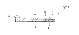
- the ceiling panel 4, the wall panel 5, and the floor panel are formed by sandwiching a sheet-like or plate-like power transmission coil 10 between the base 8 and the decorative board 9. 6 etc. are formed, and each building unit 7 is constructed by installing these building members.
- the power transmission coil 10 is provided in the outdoor H2 side rather than the inner surface 9a of the building members 4, 5, and 6 which divide and form the indoor space H1.
- a power transmission line 10 (not shown) connected to a power source is provided on the ceiling panel 4, wall panel 5, floor panel 6, etc. By being connected to the power supply, power can be supplied from the power source to each power transmission coil 10.
- the power receiving coil has the same resonance frequency as that of the power transmission coil 10 and is attached to an electric device (load) such as a home appliance and then directly connected to the electric device or a power transmission line. Or the like, and is appropriately disposed in the indoor space H1 or the outdoor H2 of the building A.
- the “same resonance frequency” is not limited to completely the same, but means substantially the same.
- the building A including the power transmission coil 10 having the above-described configuration when a current having the same frequency as the resonance frequency is passed from the power source to the power transmission coil 10, the magnetic field between the power transmission coil 10 and the power reception coil vibrates, A resonance phenomenon occurs between the power transmission coil 10 and the power reception coil.
- the resonance phenomenon is generated in this way, electric power is supplied from the power transmission coil 10 to the power reception coil and eventually to the electric device via a magnetic field generated between the power transmission coil 10 and the power reception coil.
- the transmission coil 10 of the magnetic resonance type non-contact power feeding system that can make the power transmission distance longer than the electromagnetic induction method and can transmit larger power than the radio method is provided.
- the degree of freedom of arrangement of electrical equipment such as home appliances is increased, the indoor design can be easily changed, the floor plan is not restricted, and the floor plan is not determined from the viewpoint of power supply when the building A is designed. It will be better. In particular, after the building A is completed, the floor plan and the design of the indoor H1 can be easily changed afterwards.
- the economic burden can be reduced when the floor plan is changed after the fact. Thereby, it can change to the indoor design matched with the fashion, and it becomes possible to easily cope with the design change of the building A such as a house that evolves with the times.
- the building A of this embodiment is constructed using a unit method. Further, in the frame structure 3 of the building unit 7, C-type steel is used for the steel beam 2 used as a ceiling beam or a floor beam, and a square steel pipe is used for the steel column 1.
- C-type steel is used for the steel beam 2 used as a ceiling beam or a floor beam
- a square steel pipe is used for the steel column 1.
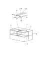
- through-holes 11 are previously drilled in each of adjacent steel beams 2 (ceiling beams). It has been installed, and the electric wires 12 are passed through the through holes 11 so that the wiring between the building units 7 adjacent to each other is performed.
- the electric wires 12 connected to the switches in the factory are connected at the construction site. However, in order to avoid shortage of the wiring length at the construction site, the electric wires 12 are left longer. In this case, the long remaining electric wires 12 are spirally wound and placed on the ceiling 4, and the building units 7 are transported from the factory to the construction site.
- the magnetic field resonance power feeding system may be applied to the connection between the building units 7 adjacent to each other. That is, a small power transmission coil 10a is pasted on one steel beam 2 (ceiling beam or floor beam) of building units 7 adjacent to each other, and a power receiving coil is installed on the steel beam 2 (ceiling beam or floor beam) of the other building unit 7. You may affix 13a. In this case, when installing each building unit 7 in a predetermined position, it is preferable to install so that the power transmission coil 10a and the power reception coil 13a face each other. Furthermore, when the through hole 11 is formed in each steel beam 2 (ceiling beam or floor beam), it is preferable to provide the power transmission coil 10a and the power receiving coil 13a so as to cover the through hole 11.
- the amount of wiring tends to increase. If the size of the through holes 11 formed in the steel beam 2 (ceiling beam, etc.) of the building unit 7 is increased or the number of the through holes 11 is increased in accordance with the increase in the wiring amount, the steel beam The strength of 2 may decrease.
- the power transmission coil 10a and the power reception coil 13a as described above and performing power transmission between the adjacent building units 7, the through hole 11 is not required, so that IT is used in a house or the like. It becomes possible to respond flexibly and surely to all electrification.
- the power transmission coils 10 and 10a of the magnetic field resonance type non-contact power feeding system are provided as in the present embodiment and the non-contact power feeding is performed to the electrical equipment in the indoor H1 of the building A, There is no limit on the number of electric devices to be fed. Therefore, even if the number of electric devices to be used increases due to the spread of IT in homes and the like, and the spread of all-electric electrification, it becomes possible to respond reliably.
- the building A which concerns on 1st Embodiment of this invention was demonstrated, this invention is not limited only to the structure of the said embodiment, In the range which does not deviate from the meaning, it can change suitably.
- the building A is constructed by the unit construction method has been described, but it may be constructed by other construction methods such as a general conventional wooden construction method. Even in this case, it is possible to obtain the same effect as the present embodiment by providing the building member with the power transmission coil 10 and the power transmission coil 10a.
- the power transmission coil 10 is located in the outermost layer which faces the outdoor H2 from the inner wall facing the indoor space H1 to the outer wall, the roof, etc., that is, from the innermost building member (for example, the decorative board 9) forming the indoor space H1.
- the power transmission coil 10 is not exposed to the indoor space H1, and the indoor design of the indoor space H1 of the building A can be prevented from being damaged by the power transmission coil 10.
- an electric wire may be printed on an interior cloth to form the power transmission coil 10, and the power transmission coil 10 may be attached to the outermost building member (the outermost surface side) forming the indoor space H1 together with the cloth.
- the power transmission coil 10 can be easily provided on the building member by printing the electric wire on the cloth, and the cloth is attached to the wall panel 5 or the ceiling panel 4 so as to surround the indoor space H1.
- the power transmission coil 10 can be easily formed on the building A.
- a repeater that resonates at the same frequency as the power transmission coils 10 and 10 a may be provided between the power transmission coils 10 and 10 a and the power reception coil 13.
- a repeater that resonates at the same frequency as the power transmission coils 10 and 10 a
- the power supply efficiency can be maintained.
- limiting of the distance between the power transmission coil 10 and the receiving coil 13 becomes small, the freedom degree of arrangement
- the building of this embodiment is a house, a store, an office building, etc., as in the first embodiment, and is constructed using, for example, a unit method.
- a frame structure 103 having, for example, a ramen structure formed by connecting a plurality of steel columns 101 and a plurality of steel beams 102 (building members) at a factory, a ceiling panel 104, The wall panel 105, the floor panel 106, etc. (building member) are installed, and the rectangular parallelepiped building unit 107 is constructed.
- the plurality of building units 107 are transported to the construction site, installed on the foundation structure, and arranged side by side. Further, the upper building unit 107 is stacked on the lower building unit 107.
- the building B is constructed by integrating the plurality of building units 107 with each other.
- building B when building B is constructed using such a unit method, the construction efficiency of building B can be increased, and high structural strength can be ensured.
- the building B of the present embodiment is provided with a non-contact power feeding system for feeding power to electrical equipment (load) such as home appliances in a non-contact manner as in the first embodiment.
- This non-contact power supply system is a magnetic resonance type power supply system, and includes a power transmission coil (power transmission side device, magnetic field generator) and a power reception coil (power reception side device).
- the building B of this embodiment is assembled by installing the ceiling panel 104, the wall panel 105, the floor panel 106, etc. with respect to the frame structure.
- the power transmission coil is comprised with respect to a series of building members surrounding the indoor space H3 of this building B.
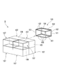
- FIG. And the power transmission coil of this embodiment is provided with the division
- the baseboard 110 that is a parting material attached along the lower edge of each wall panel 105 is selected as the series of building members.
- the skirting board 110 has a built-in electric wire 112 forming the power transmission coil 111.
- the skirting board 110 is divided into four so as to surround the indoor space H3 when seen in a plan view.
- Each divided baseboard 110 baseboard piece
- a plurality of electric wires 112 (divided electric wires) constituting the power transmission coil 111 built in each skirting board 110 are arranged along the longitudinal direction (extending direction) of the skirting board 110.
- each base board 110 is provided so as to form a loop surrounding the indoor space H3 along the arrangement direction of the trees 110.
- each connector 113 has a built-in conductive member 114 such as an L-shaped lead for electrically connecting the electric wire 112 built in one adjacent baseboard 110 and the electric wire 112 built in the other baseboard 110. is doing. That is, each connector 113 has a role of mechanically connecting the baseboards 110 and a role of electrically connecting the electric wires 112.
- a plurality of (four) skirting boards 110 are arranged so as to surround the indoor space H3 by connecting the ends of the adjacent skirting boards 110 so as to form a right angle between each other using the connector 113. Is done. Then, the electric wires 112 respectively built in the adjacent baseboards 110 are electrically connected via the connector 113 so as to form a coil shape, and when viewed in plan, the power transmission coil 111 is rectangular so as to surround the indoor space H3. Is formed.
- the electric wire 112 which comprises the power transmission coil 111 is provided in each of a series of baseboard 110 (building member) arrange
- the power receiving coil 119 a has the same resonance frequency as that of the power transmitting coil 111, and is attached to an electric device (load) 119 such as a home appliance, and then is electrically connected to the electric device 119.
- load an electric device
- it is appropriately arranged in the indoor space H3 of the building B by connecting directly or via a power transmission line.
- the “same resonance frequency” is not limited to completely the same, but means substantially the same.
- a power transmission coil 111 of the system is provided.
- the power transmission coil 111 is provided so as to surround the indoor space H3 by being provided in a series of baseboards 110 (building members) arranged so as to surround the indoor space H3.
- the electrical equipment 119 such as home appliances at an arbitrary position in the indoor space H3 of the building B.
- the power transmission coil 111 can be reliably and easily formed so as to surround the indoor space H3 by selecting the baseboard 110 as a building member including the power transmission coil 111. It becomes possible.
- an electric wire 112 is provided for each baseboard 110 (building member) formed by dividing the rectangular frame surrounding the indoor space H3 in the circumferential direction, and the adjacent baseboards 110 are mechanically connected to each other using the connector 113. Connect. By this connection, the electric wires 112 of the skirting boards 110 adjacent to each other can also be electrically connected via the conductive member 114. As a result, the electric wires 112 are connected so as to surround the indoor space H3 and are looped.
- the power transmission coil 111 can be formed. Therefore, the power transmission coil 111 can be reliably and easily disposed so as to surround the indoor space H3.
- the power transmission coil 111 surrounding the indoor space H3 is formed by providing the power transmission coil 111 on a series of baseboards 110 arranged so as to surround the indoor space H3. It is possible to obtain the effects of the building B including the power transmission coil 111.
- the building B and its construction method concerning 2nd Embodiment of this invention were demonstrated, this invention is not limited only to the structure of the said embodiment, In the range which does not deviate from the meaning, it can change suitably. It is.
- the building B is constructed by the unit construction method has been described, but of course, it may be constructed by other construction methods such as a general conventional wooden construction method. Even in this case, it is possible to obtain the same effect as that of the present embodiment by providing the building member with the power transmission coil 111.
- the baseboard 110 was employ
- the skirting board 110 can be applied to at least one of a wall material, a floor material, and a ceiling material.
- the wall panel 105 including the electric wires 112 a laid horizontally at a predetermined height position in the vertical direction is employed, the same effect as that of the present embodiment can be obtained. Is possible. Further, for example, as shown in FIG.
- the steel beam 102 is extended by providing a power transmission coil 111 on a steel beam 102 such as a series of ceiling beams arranged so as to surround the indoor space H ⁇ b> 3 in plan view.
- the power transmission coil 111 may be formed (arranged) so as to surround the indoor space H3 along the direction.
- the electric wire 112 may be formed so as to surround the indoor space H3, and the power transmission coil 111 may be disposed with this.
- the electric wire 112 can be easily provided on the building member by printing the electric wire 112 on the cloth.
- the power transmission coil 111 can be easily formed on the building B by pasting the cloth on the wall panel 105 or the ceiling panel 104 so as to surround the indoor space H3.
- the building of this embodiment is a house, a store, an office building, etc., as in the first embodiment, and is constructed using, for example, a unit method.
- a plurality of steel columns and a plurality of steel beams are connected and formed, for example, ramen Ceiling panels, wall panels, floor panels, etc. (building members) are installed on the structural framework structure to construct a rectangular parallelepiped building unit.
- a some building unit is conveyed to a construction site, and it installs in parallel on a foundation structure.
- the upper building unit is stacked on the lower building unit.
- a building is constructed by integrating the plurality of building units with each other.
- the building of this embodiment is also equipped with the non-contact electric power feeding system for supplying electric power non-contactingly with respect to electric equipments (load), such as a household appliance, similarly to the building A of the said 1st Embodiment.
- the non-contact power supply system is a magnetic field resonance type power supply system, and includes a power transmission coil (power transmission side device, magnetic field generator) and a power reception coil (power reception side device).
- the size, number, and arrangement of the power transmission coils are different from the configuration of the first embodiment. Hereinafter, the difference will be mainly described.
- FIG. 10 shows the building unit 207 of the present embodiment, which corresponds to the building unit 7 described in the first embodiment.
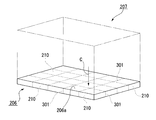
- the single big power transmission coil 10 was provided so that the substantially whole surface of the floor panel 6 of the building unit 7 might be enclosed was demonstrated in the said 1st Embodiment, as shown in FIG.10 and FIG.11 in this embodiment.
- a plurality of power transmission coils 210 (small coils) smaller than the power transmission coil 10 are provided in the floor panel 206 so as to cover the entire surface of the floor panel 206 when viewed in plan.
- the floor panel 206 of this embodiment includes a bottom wall 352; a plurality of joists 301 standing on the bottom wall 352; and a flooring 306 supported on these joists 301; At least a power transmission coil 210, a heat insulating material 303, a particle board 304, and a sail sheet 305 disposed in a space 302 defined by a bottom wall 352, a joist 301 and a flooring 306.
- the flooring 306 is supported by a plurality of joists 301 arranged in a lattice pattern, and the power transmission coils 210 are individually arranged in a rectangular space 302 partitioned by these joists 301. Has been.
- Each power transmission coil 210 forms a substantially quadrangle (square or rectangle) surrounding the space 302 when viewed in plan.
- the power transmission coil of the present embodiment includes the power transmission coils 210 that are a plurality of small coils, and the power transmission coils 210 divide the indoor surface 206a that is the upper surface of the floor panel 206 into a plurality of regions. , Arranged vertically and horizontally. As a pitch between the joists 301, for example, 45 cm can be adopted.
- each power transmission coil 210 is disposed between the pair of joists 301 provided on the bottom wall 352 so as to surround the space 302.
- a heat insulating material 303 is spread in the space 302 so as to cover the power transmission coil 210 from above, and a particle board 304 and a sill sheet 305 are further spread in this order.
- the flooring 306 is applied to the upper surface of the joist 301.
- each member from the heat insulating material 303 to the flooring 306 does not include metal, it does not hinder the generation of the magnetic field 350 for receiving power in the indoor space. For the same reason, during construction, it is necessary not to provide a metal heat insulating film such as an aluminum sheet, which may adversely affect the formation of the magnetic field 350, above the power transmission coil 210.
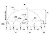
- FIG. 13 shows the distribution in the direction along the surface of the floor panel 206 of the magnetic field 350 formed by each power transmission coil 210 of the present embodiment and the magnetic field 351 formed by the power transmission coil 10 described in the first embodiment.
- the horizontal axis indicates the arrangement of the power transmission coil 10 or 210 from one end of the floor panel 206 to the other end, and the vertical axis indicates the height from the floor where the magnetic field reaches.
- the power transmission coil 210 of the present embodiment is disposed between the joists 301 and generates a magnetic field 350 having a substantially semicircular intensity distribution. Since the size of each power transmission coil 210 is smaller than the size of the power transmission coil 10 of the first embodiment, the range covered by the magnetic field (that is, the width dimension in the horizontal direction and the height in the vertical direction) is relatively small. As a result, a plurality of magnetic fields 350 having a lower magnetic field than the power transmission coil 10 of the first embodiment are formed to cover the upper surface of the floor panel 206. Therefore, as compared with the magnetic field 351 having the height H2 formed by the power transmission coil 10, the magnetic field strength can be suppressed to a desired height H1 (for example, about 1.5 m) as a whole.
- a desired height H1 for example, about 1.5 m
- the height H ⁇ b> 2 that the magnetic field 351 reaches is increased according to the size of the power transmission coil 10, so that the electric device 308 (load) disposed at a relatively high position relatively far from the floor panel 206. This is suitable for receiving power with the power receiving coil 308a.
- the floor surface of the floor panel 206 is partitioned in a grid pattern, and the power transmission coil 210 is arranged in each partition. Therefore, the renovation work for changing the indoor design of the building unit 207 Can be flexibly dealt with. That is, referring to FIG. 13 again, even if it is necessary to newly provide a partition wall at the position W1 in the figure for the purpose of changing the indoor design, the three power transmission coils 210 from the left side of the drawing Magnetic fields with the same height as before the renovation work can be distributed indoors.
- the size may be different for each arrangement location. For example, when it is desired to increase the magnetic field strength (the range covered by the magnetic field), a larger power transmission coil 210 is installed, and when it is desired to lower it, a smaller power transmission coil 210 is installed.
- the term “large” or “small” refers to the size of the area surrounded by the loop formed by the power transmission coil 210.
- the power transmission coil 210 is provided in the heat insulating material 303. You may make it integrate and integrate. In this case, the heat insulating material 303 containing the power transmission coil 210 is manufactured in advance in the factory, transported to the renovation site, and the floor panel 206 of the building unit 207 is peeled off, and then the old heat insulating material is removed. Instead, a new heat insulating material 303 is installed.
- the old heat insulating material 303 is removed and a new heat insulating material 303 is installed instead.
- the heat insulating material 303 may be changed for each installation location so that the indoor distribution in the range of (1) reaches a desired distribution. For example, in a place where it is desired to increase the magnetic field strength (the range covered by the magnetic field), the heat insulating material 303 including the large power transmission coil 210 is disposed, while the magnetic field strength (the range covered by the magnetic field) is desired to be low or zero.
- a heat insulating material 303 with a small power transmission coil 210 built therein or a heat insulating material 303 that does not include the power transmission coil 210 may be disposed at a place where the power transmission coil 210 is desired.
- the power transmission coil 210 may be provided integrally with the joist 301 itself. In that case, it is possible to install a large number of power transmission coils 210 at the same time only by installing joists 301.
- the power transmission coil 210 may be provided integrally only on either the heat insulating material 303 or the joist 301 as described above, or may be provided integrally on both if necessary. You may do it.
- each power transmission coil 210 of the present embodiment is connected in parallel to the power supply via a control circuit, and the current value flowing through each power transmission coil 210 can be individually controlled. It has become. By such control, the current value can be finely adjusted for each power transmission coil 210, so that the magnetic field intensity generated for each power transmission coil 210 can be finely adjusted.
- a region where the magnetic field strength is partially increased or a region where the magnetic field strength is lowered is formed to increase or decrease the magnetic field strength distribution along the floor surface. It is possible.
- a wiring is provided so as to straddle the upper surface of each joist 301 and the power transmission adjacent to each other is provided by this wiring.
- the coils 210 can be electrically connected.
- a repeater (relay unit) (not shown) may be provided between the power transmission coils 210 and wirelessly connected via the repeater. In this case, a plurality of repeaters are required. However, since the manufacturing cost of the repeater itself is low, the construction cost is not greatly affected. Rather, the advantage of the high degree of construction freedom by wireless connection is better.
- the building provided with the power transmission coil of the non-contact electric power feeding system which can perform the electric power feeding to a load, without receiving restrictions by indoor floor plans etc., and the construction method of this building are provided. be able to.
- Ceiling panel (ceiling material) 5 Wall materials (wall panels) 6,206 Floor material (floor panel) 8 Other building components (base) located in the outermost layer 9 Building material (decorative board) located in the innermost layer 10, 111 Power transmission coil 110 Plural building members, skirting boards 112 electric wires (divided electric wires) 113 connector 206a indoor surface 210 power transmission coil, small coil A, B building H1, H3 indoor space
Landscapes
- Engineering & Computer Science (AREA)
- Power Engineering (AREA)
- Computer Networks & Wireless Communication (AREA)
- Architecture (AREA)
- Physics & Mathematics (AREA)
- Electromagnetism (AREA)
- Civil Engineering (AREA)
- Structural Engineering (AREA)
- Building Environments (AREA)
Abstract
Description
本願は、2011年03月31日に、日本国に出願された特願2011-078081号と、2011年03月31日に、日本国に出願された特願2011-078082号とに基づき優先権を主張し、これらの内容をここに援用する。
本発明は、上記接触式の給電システム及び電磁誘導方式による非接触給電用パネルが有する課題を解消して、屋内の間取りの制約やデザインの自由度の規制、そして負荷配置の制約を緩和させることを可能にした、非接触給電システムの送電コイルを備えた建築物と、この建築物の施工方法とを提供することを課題とする。
(1)本発明の一態様に係る建築物は、磁界共鳴式の非接触給電システムの送電コイルを備えている。
(2)上記(1)に記載の建築物において、屋内空間に面する最内層に位置する建築部材と、屋外に面する最外層に位置する他の建築部材との間に、前記送電コイルが配置されていてもよい。
(3)上記(1)又は(2)に記載の建築物において、前記送電コイルと同じ周波数で共鳴するリピータをさらに備えてもよい。
(5)上記(4)に記載の建築物の場合、前記送電コイルが、前記建築部材毎に分割された分割電線と、これら分割電線間を電気的に接続するコネクタとを備えてもよい。
(7)上記(1)~(6)の何れか一項に記載の建築物において、屋内空間に面する屋内面を有する建築部材をさらに備え;前記送電コイルが複数の小コイルを含んでかつ、これら小コイルが前記屋内面を複数領域に区画するように配列されている;構成を採用してもよい。
(8)上記(7)に記載の建築物において、前記建築部材が、格子状に配置された根太と、これら根太間に配された断熱材とを備えた床材であり;前記断熱材及び前記根太の少なくとも一方に、前記小コイルが一体に設けられている;構成を採用してもよい。
(9)上記(7)または(8)に記載の建築物において、前記小コイルの大きさが、前記領域毎に異なってもよい。
上記(9)に記載の建築物の場合、改築工事により屋内デザインを変更する際、改築後の室内レイアウトに応じて、領域毎に、磁界強度及び磁界が及ぶ範囲に強弱を自由に付けることができる。
以下、図1から図5を参照しながら、本発明の第1実施形態に係る建築物について説明する。
また、電線を予め備えた、壁パネル5、鉄骨梁2、その他の建築部材を適宜組み合わせることで、屋内空間H1内に複数の送電コイル10を配設してもよい。
以下、図6から図9を参照しながら、本発明の第2実施形態に係る建築物及びその施工方法について説明する。
本実施形態の建築物Bを施工する際には、屋内空間H3を取り囲むように配設される一連の幅木110(建築部材)のそれぞれに送電コイル111をなす電線112を設け、この幅木110を各壁パネル105の下端縁に設置するとともに、幅木110の延在方向に沿って屋内空間H3を取り囲む送電コイル111を形成する。すなわち、本実施形態に係る建築物の施工方法は、全体としてループをなす送電コイル111をその延在方向に沿った複数箇所で分割した電線112がそれぞれ設けられた複数の幅木110を、屋内空間H3を囲むように連接する工程と;各電線112間をコネクタ113により電気的に接続することで、屋内空間H3を囲む送電コイル111を形成する工程と;を含む。
このようにして、複数の建物ユニット107を設置して建築物Bを構築した後に、図示しない電源に繋がる送電線を、幅木110に設けた送電コイル111(電線112)に接続する。
さらに、例えば図9に示すように、平面視した場合に屋内空間H3を取り囲むように配設される一連の天井梁などの鉄骨梁102に送電コイル111を設けることによって、鉄骨梁102の延在方向に沿って屋内空間H3を取り囲むように送電コイル111を形成(配設)してもよい。勿論、この場合においても、上記実施形態と同様の作用効果を得ることが可能である。
また、例えば、内装のクロスに印刷して電線112を形成し、屋内空間H3を形成する最表面(最表面側)に位置する建築部材の表面側又は裏面側にクロスを貼り付けることで、各電線112を、屋内空間H3を囲むように形成し、これをもって送電コイル111を配設してもよい。このように、クロスに電線112を印刷することで、容易に、電線112を建築部材に設けることができる。また、このクロスを、屋内空間H3を取り囲むように壁パネル105や天井パネル104に貼り付けることによって、容易に、建築物Bに送電コイル111を形成することが可能となる。
また、電線112を備えた壁パネル105や幅木110、電線112を備えた梁やその他の建築部材を適宜組み合わせて、屋内空間H3を囲む複数の送電コイル111を配設してもよい。
以下、図10から図13を参照しながら、本発明の第3実施形態に係る建築物について説明する。
図11に示すように、フローリング306は、格子状に配置された複数本の根太301により支持されているが、これら根太301により区画された四角形の空間302内に、送電コイル210が個別に配置されている。各送電コイル210は、平面視した場合に空間302を囲む略四角形(正方形又は長方形)を成している。このように、本実施形態の送電コイルは、複数の小コイルである送電コイル210を備え、なおかつ、これら送電コイル210が、床パネル206の上面である屋内面206aを複数領域に区画するように、縦横に配列されている。なお、各根太301間のピッチとしては、例えば45cmを採用することができる。
一方、前記送電コイル10の場合には、その大きさに応じて磁界351の及ぶ高さH2が高くなるので、床パネル206より比較的離れた高い位置に配置された電気機器308(負荷)の受電コイル308aで受電する場合などに適している。
また、屋内で得られる磁界強度(磁界の及ぶ範囲)の屋内分布が所望の分布となるようにしたい場合、本実施形態では、各領域(各区画)内のそれぞれに送電コイル210を配置する構成を採用しているので、その大きさを配置場所毎に異ならせても良い。例えば、磁界強度(磁界の及ぶ範囲)を高くしたい場合には大きめの送電コイル210を設置する一方、低くしたい場合には小さめの送電コイル210を設置する。なお、ここで言う大きい、小さいとは、送電コイル210が形成するループにより囲まれる面積の大小を言う。
さらに言うと、屋内の間取りを変えるための改築工事を行う場合、古い断熱材303を取り除いた上で、新たな断熱材303を代わりに設置するが、改築後の屋内で得られる磁界強度(磁界の及ぶ範囲)の屋内分布が所望の分布となるように、設置場所毎に断熱材303を変えても良い。例えば、磁界強度(磁界の及ぶ範囲)を高めにしたい場所には、大きめの送電コイル210を内蔵した断熱材303を配置する一方、磁界強度(磁界の及ぶ範囲)を低めにしたいか、またはゼロにしたい場所には、小さめの送電コイル210を内蔵した断熱材303か、または送電コイル210を備えない断熱材303を配置してもよい。
なお、送電コイル210を一体に設ける場合には、上述のように断熱材303または根太301の何れか一方のみに一体に設けても良いし、または、必要に応じて両方に対して一体に設けるようにしてもよい。
5 壁材(壁パネル)
6,206 床材(床パネル)
8 最外層に位置する他の建築部材(下地)
9 最内層に位置する建築部材(化粧板)
10,111 送電コイル
110 連設された複数の建築部材,幅木
112 電線(分割電線)
113 コネクタ
206a 屋内面
210 送電コイル,小コイル
A,B 建築物
H1,H3 屋内空間
Claims (10)
- 磁界共鳴式の非接触給電システムの送電コイルを備えていることを特徴とする建築物。
- 屋内空間に面する最内層に位置する建築部材と、屋外に面する最外層に位置する他の建築部材との間に、前記送電コイルが配置されていることを特徴とする請求項1に記載の建築物。
- 前記送電コイルと同じ周波数で共鳴するリピータをさらに備えることを特徴とする請求項1に記載の建築物。
- 屋内空間を取り囲むように連設された複数の建築部材をさらに備え;
前記送電コイルが、前記各建築部材の並び方向に沿って前記屋内空間を取り囲むループをなすように、前記各建築部材に設けられている;
ことを特徴とする請求項1に記載の建築物。 - 前記送電コイルが、前記建築部材毎に分割された分割電線と、これら分割電線間を電気的に接続するコネクタとを備えることを特徴とする請求項4に記載の建築物。
- 前記建築部材が、壁材、幅木、床材、天井材、のうちの少なくとも一つであることを特徴とする請求項4または5に記載の建築物。
- 屋内空間に面する屋内面を有する建築部材をさらに備え;
前記送電コイルが複数の小コイルを含んでかつ、これら小コイルが前記屋内面を複数領域に区画するように配列されている;
ことを特徴とする請求項1に記載の建築物。 - 前記建築部材が、格子状に配置された根太と、これら根太間に配された断熱材とを備えた床材であり;
前記断熱材及び前記根太の少なくとも一方に、前記小コイルが一体に設けられている;
ことを特徴とする請求項7に記載の建築物。 - 前記小コイルの大きさが、前記領域毎に異なることを特徴とする請求項7または8に記載の建築物。
- 送電コイルをその線材に沿った複数箇所で分割した分割電線がそれぞれ設けられた複数の建築部材を、屋内空間を囲むように連接する工程と;
前記各分割電線間を電気的に接続することで、前記屋内空間を囲む前記送電コイルを形成する工程と;
を有することを特徴とする建築物の施工方法。
Priority Applications (3)
| Application Number | Priority Date | Filing Date | Title |
|---|---|---|---|
| US14/005,703 US10176920B2 (en) | 2011-03-31 | 2012-03-30 | Building and construction method for the same |
| JP2013507781A JP5847161B2 (ja) | 2011-03-31 | 2012-03-30 | 建築物及びその施工方法 |
| CN201280015454.5A CN103460554B (zh) | 2011-03-31 | 2012-03-30 | 建筑物及其施工方法 |
Applications Claiming Priority (4)
| Application Number | Priority Date | Filing Date | Title |
|---|---|---|---|
| JP2011-078082 | 2011-03-31 | ||
| JP2011078081 | 2011-03-31 | ||
| JP2011078082 | 2011-03-31 | ||
| JP2011-078081 | 2011-03-31 |
Publications (1)
| Publication Number | Publication Date |
|---|---|
| WO2012133762A1 true WO2012133762A1 (ja) | 2012-10-04 |
Family
ID=46931459
Family Applications (1)
| Application Number | Title | Priority Date | Filing Date |
|---|---|---|---|
| PCT/JP2012/058571 Ceased WO2012133762A1 (ja) | 2011-03-31 | 2012-03-30 | 建築物及びその施工方法 |
Country Status (4)
| Country | Link |
|---|---|
| US (1) | US10176920B2 (ja) |
| JP (1) | JP5847161B2 (ja) |
| CN (1) | CN103460554B (ja) |
| WO (1) | WO2012133762A1 (ja) |
Cited By (4)
| Publication number | Priority date | Publication date | Assignee | Title |
|---|---|---|---|---|
| WO2014068849A1 (ja) * | 2012-10-31 | 2014-05-08 | パナソニック 株式会社 | 非接触給電システム、可動装置及び非接触給電システムの給電制御方法 |
| JP2017045675A (ja) * | 2015-08-28 | 2017-03-02 | 株式会社Lixil | 温度制御システム |
| WO2021111880A1 (ja) * | 2019-12-05 | 2021-06-10 | パナソニック液晶ディスプレイ株式会社 | 無線電力伝送ユニット、無線電力伝送システム、無線電力伝送ユニットの設置方法 |
| CN111813056B (zh) * | 2020-06-02 | 2023-05-23 | 深圳全景空间工业有限公司 | 一种调节室内环境的方法 |
Families Citing this family (10)
| Publication number | Priority date | Publication date | Assignee | Title |
|---|---|---|---|---|
| JP5646425B2 (ja) * | 2011-09-28 | 2014-12-24 | 株式会社東芝 | 電子機器 |
| JP5817500B2 (ja) * | 2011-12-16 | 2015-11-18 | 株式会社Ihi | 給電システム及び非接触給電方法 |
| US9780573B2 (en) * | 2014-02-03 | 2017-10-03 | Witricity Corporation | Wirelessly charged battery system |
| WO2016038772A1 (ja) * | 2014-09-11 | 2016-03-17 | パナソニックIpマネジメント株式会社 | 建物ユニット及び建物 |
| CN107026494B (zh) * | 2017-04-25 | 2024-04-02 | 常州大学 | 用于室内的三维无线充电结构 |
| WO2020161666A1 (en) | 2019-02-07 | 2020-08-13 | Powermat Technology Ltd | Wireless power transmission system |
| DE102021112872A1 (de) * | 2021-05-18 | 2022-11-24 | expo steel Gesellschaft für Planung und Ausführung mbH | Modulares Gebäude mit einer einen Innenraum umgebenden Stützkonstruktion |
| NL2033101B1 (en) * | 2022-09-22 | 2024-03-26 | Copiam Floor Systems B V | Modular building unit |
| US12595932B2 (en) * | 2022-11-11 | 2026-04-07 | Rheem Manufacturing Company | Systems and methods for powering water heating devices using wireless power transmissions |
| US12388266B1 (en) | 2024-03-26 | 2025-08-12 | Hyve Systems, Inc. | Mobile distributed energy resource transport system and methods of use |
Citations (9)
| Publication number | Priority date | Publication date | Assignee | Title |
|---|---|---|---|---|
| WO2009111597A2 (en) * | 2008-03-05 | 2009-09-11 | Nigel Power Llc | Packaging and details of a wireless power device |
| JP4366699B2 (ja) * | 2005-11-25 | 2009-11-18 | パナソニック電工株式会社 | 配線システム及び配線システムに用いられる延長配線モジュール |
| JP2010239848A (ja) * | 2009-03-31 | 2010-10-21 | Fujitsu Ltd | 電力伝送装置 |
| JP2010239847A (ja) * | 2009-03-31 | 2010-10-21 | Fujitsu Ltd | 送電装置、送受電装置および送電方法 |
| JP2011501633A (ja) * | 2007-10-09 | 2011-01-06 | パワーマット リミテッド | 境界面内の誘導電力提供システム |
| JP2011030317A (ja) * | 2009-07-23 | 2011-02-10 | Sony Corp | 非接触給電システム、非接触中継装置、非接触受電装置および非接触給電方法 |
| JP2011151901A (ja) * | 2010-01-19 | 2011-08-04 | Panasonic Electric Works Co Ltd | 非接触給電機能付き化粧材、および非接触給電機能付き面状構造物 |
| JP2011151900A (ja) * | 2010-01-19 | 2011-08-04 | Panasonic Electric Works Co Ltd | 非接触給電システム |
| JP2012016250A (ja) * | 2010-07-05 | 2012-01-19 | Panasonic Electric Works Co Ltd | 非接触給電機能付き什器 |
Family Cites Families (8)
| Publication number | Priority date | Publication date | Assignee | Title |
|---|---|---|---|---|
| US6235988B1 (en) * | 1999-05-28 | 2001-05-22 | Pent Assemblies, Inc. | Wall panel assembly |
| JP2005143181A (ja) * | 2003-11-05 | 2005-06-02 | Seiko Epson Corp | 非接触電力伝送装置 |
| US7952322B2 (en) * | 2006-01-31 | 2011-05-31 | Mojo Mobility, Inc. | Inductive power source and charging system |
| US20100219183A1 (en) * | 2007-11-19 | 2010-09-02 | Powermat Ltd. | System for inductive power provision within a bounding surface |
| KR101261686B1 (ko) * | 2007-11-28 | 2013-05-06 | 퀄컴 인코포레이티드 | 무급전 안테나를 사용한 무선 전력 범위 증가 |
| JP2009159675A (ja) | 2007-12-25 | 2009-07-16 | Panasonic Electric Works Co Ltd | 非接触給電用パネル |
| US9312924B2 (en) * | 2009-02-10 | 2016-04-12 | Qualcomm Incorporated | Systems and methods relating to multi-dimensional wireless charging |
| JP2011030318A (ja) | 2009-07-23 | 2011-02-10 | Sony Corp | 非接触給電装置、非接触受電装置、非接触給電装置における優先度表示方法および非接触受電装置における優先度表示方法 |
-
2012
- 2012-03-30 WO PCT/JP2012/058571 patent/WO2012133762A1/ja not_active Ceased
- 2012-03-30 JP JP2013507781A patent/JP5847161B2/ja not_active Expired - Fee Related
- 2012-03-30 US US14/005,703 patent/US10176920B2/en not_active Expired - Fee Related
- 2012-03-30 CN CN201280015454.5A patent/CN103460554B/zh not_active Expired - Fee Related
Patent Citations (9)
| Publication number | Priority date | Publication date | Assignee | Title |
|---|---|---|---|---|
| JP4366699B2 (ja) * | 2005-11-25 | 2009-11-18 | パナソニック電工株式会社 | 配線システム及び配線システムに用いられる延長配線モジュール |
| JP2011501633A (ja) * | 2007-10-09 | 2011-01-06 | パワーマット リミテッド | 境界面内の誘導電力提供システム |
| WO2009111597A2 (en) * | 2008-03-05 | 2009-09-11 | Nigel Power Llc | Packaging and details of a wireless power device |
| JP2010239848A (ja) * | 2009-03-31 | 2010-10-21 | Fujitsu Ltd | 電力伝送装置 |
| JP2010239847A (ja) * | 2009-03-31 | 2010-10-21 | Fujitsu Ltd | 送電装置、送受電装置および送電方法 |
| JP2011030317A (ja) * | 2009-07-23 | 2011-02-10 | Sony Corp | 非接触給電システム、非接触中継装置、非接触受電装置および非接触給電方法 |
| JP2011151901A (ja) * | 2010-01-19 | 2011-08-04 | Panasonic Electric Works Co Ltd | 非接触給電機能付き化粧材、および非接触給電機能付き面状構造物 |
| JP2011151900A (ja) * | 2010-01-19 | 2011-08-04 | Panasonic Electric Works Co Ltd | 非接触給電システム |
| JP2012016250A (ja) * | 2010-07-05 | 2012-01-19 | Panasonic Electric Works Co Ltd | 非接触給電機能付き什器 |
Cited By (6)
| Publication number | Priority date | Publication date | Assignee | Title |
|---|---|---|---|---|
| WO2014068849A1 (ja) * | 2012-10-31 | 2014-05-08 | パナソニック 株式会社 | 非接触給電システム、可動装置及び非接触給電システムの給電制御方法 |
| US10177599B2 (en) | 2012-10-31 | 2019-01-08 | Panasonic Intellectual Property Management Co., Ltd. | Contactless power feeding system, movable device and method for controlling power feeding of contactless power feeding system |
| JP2017045675A (ja) * | 2015-08-28 | 2017-03-02 | 株式会社Lixil | 温度制御システム |
| WO2017038153A1 (ja) * | 2015-08-28 | 2017-03-09 | 株式会社Lixil | 温度制御システム |
| WO2021111880A1 (ja) * | 2019-12-05 | 2021-06-10 | パナソニック液晶ディスプレイ株式会社 | 無線電力伝送ユニット、無線電力伝送システム、無線電力伝送ユニットの設置方法 |
| CN111813056B (zh) * | 2020-06-02 | 2023-05-23 | 深圳全景空间工业有限公司 | 一种调节室内环境的方法 |
Also Published As
| Publication number | Publication date |
|---|---|
| US10176920B2 (en) | 2019-01-08 |
| JP5847161B2 (ja) | 2016-01-20 |
| CN103460554B (zh) | 2017-06-23 |
| US20140008996A1 (en) | 2014-01-09 |
| JPWO2012133762A1 (ja) | 2014-07-28 |
| CN103460554A (zh) | 2013-12-18 |
Similar Documents
| Publication | Publication Date | Title |
|---|---|---|
| JP5847161B2 (ja) | 建築物及びその施工方法 | |
| US4596095A (en) | Underfloor cable tray assembly | |
| CN110469048B (zh) | 一种装配式墙体的布线方法 | |
| CN102947899A (zh) | Rf信号分配的多通道布线 | |
| JP6882286B2 (ja) | 壁や天井に電気的に接続可能な仕切りを備えた拡張可能な部屋 | |
| CN212104683U (zh) | 转接件、基板内管线集成装置及隔墙内管线集成系统 | |
| KR101930368B1 (ko) | 입상 케이블 트레이용 슬리브의 무볼트 조인트 커넥터 장치 | |
| JP7738456B2 (ja) | 配線室の施工方法、及び配線室ユニット | |
| JP5035736B1 (ja) | ユニットハウス用配線システム | |
| JP2025031473A (ja) | フロアコンセントボックスを有する建築物の床構造 | |
| JP2015036492A (ja) | ユニット式建物の配管構造及び方法 | |
| JP5215910B2 (ja) | 配線ダクト | |
| KR20170104018A (ko) | 전기 온돌판넬 및 이를 갖는 전기 온돌시스템 | |
| CN111188438A (zh) | 隔墙内管线集成系统及安装方法 | |
| JP6255041B2 (ja) | ユニットハウス | |
| NL2016078B1 (en) | Preassembled electrical wiring assembly for a building. | |
| US12571209B2 (en) | Wall panel | |
| JP7503874B1 (ja) | フロアコンセントボックスを有するログハウスの床構造 | |
| JP7615471B2 (ja) | 床構造及び床構造の施工方法 | |
| US12206230B2 (en) | Power cable system prefabricated in a building structure | |
| EP4193439B1 (en) | Structured cabling for "intelligent buildings" | |
| JP3178394U (ja) | 組立てハウス用配線システム | |
| JP2018206049A (ja) | 建物、建物の電気供給方法、建物の冷却水供給方法、及び、建物の構築方法 | |
| JP4792265B2 (ja) | Oa機器の接地機能を高めたフロア | |
| CN105337222A (zh) | 一种idc机房六类线的布放施工方法 |
Legal Events
| Date | Code | Title | Description |
|---|---|---|---|
| 121 | Ep: the epo has been informed by wipo that ep was designated in this application |
Ref document number: 12764775 Country of ref document: EP Kind code of ref document: A1 |
|
| ENP | Entry into the national phase |
Ref document number: 2013507781 Country of ref document: JP Kind code of ref document: A |
|
| WWE | Wipo information: entry into national phase |
Ref document number: 14005703 Country of ref document: US |
|
| NENP | Non-entry into the national phase |
Ref country code: DE |
|
| 122 | Ep: pct application non-entry in european phase |
Ref document number: 12764775 Country of ref document: EP Kind code of ref document: A1 |