WO2012133283A1 - コンテナターミナルとその制御方法 - Google Patents
コンテナターミナルとその制御方法 Download PDFInfo
- Publication number
- WO2012133283A1 WO2012133283A1 PCT/JP2012/057714 JP2012057714W WO2012133283A1 WO 2012133283 A1 WO2012133283 A1 WO 2012133283A1 JP 2012057714 W JP2012057714 W JP 2012057714W WO 2012133283 A1 WO2012133283 A1 WO 2012133283A1
- Authority
- WO
- WIPO (PCT)
- Prior art keywords
- container
- carriage
- storage lane
- yard
- yard crane
- Prior art date
- Legal status (The legal status is an assumption and is not a legal conclusion. Google has not performed a legal analysis and makes no representation as to the accuracy of the status listed.)
- Ceased
Links
Images




Classifications
-
- B—PERFORMING OPERATIONS; TRANSPORTING
- B65—CONVEYING; PACKING; STORING; HANDLING THIN OR FILAMENTARY MATERIAL
- B65G—TRANSPORT OR STORAGE DEVICES, e.g. CONVEYORS FOR LOADING OR TIPPING, SHOP CONVEYOR SYSTEMS OR PNEUMATIC TUBE CONVEYORS
- B65G63/00—Transferring or trans-shipping at storage areas, railway yards or harbours or in opening mining cuts; Marshalling yard installations
- B65G63/002—Transferring or trans-shipping at storage areas, railway yards or harbours or in opening mining cuts; Marshalling yard installations for articles
- B65G63/004—Transferring or trans-shipping at storage areas, railway yards or harbours or in opening mining cuts; Marshalling yard installations for articles for containers
Definitions
- the present invention relates to a container terminal and a control method in which, in a container terminal, the movement distance of a yard crane straddling a storage lane is shortened to increase cargo handling efficiency, and energy consumption is suppressed.
- the container terminal is a facility that loads or unloads containers to / from ships, and loads and unloads containers using an external chassis for land transportation. It is also a facility that temporarily stores containers that have been loaded or unloaded.
- the storage lane is extended in a direction substantially orthogonal to the quay and equipped with an automatic guided vehicle that switches back between the storage lanes.
- a gate is provided on the opposite side of the quay side to provide an external chassis and transfer crane (yard crane). )
- a container terminal provided with an area for cargo handling (see, for example, Patent Document 1). In this container terminal, since the manned foreign chassis does not enter the storage area, the storage area ratio increases and the container terminal can be automated.
- the transfer crane (yard crane) moves on the storage lane while holding the container.
- cargo handling efficiency deteriorates. This is because the transfer speed of the transfer crane (yard crane) is as low as about 18 km / h.
- the transfer distance of the transfer crane (yard crane) is also used. You have to make more.
- the container loaded from the foreign chassis and loaded into the ship is placed on the sea side of the storage lane and unloaded from the ship. If the container to be transported to the foreign chassis is placed on the land side of the storage lane, cargo handling efficiency will increase. In the container terminal described in Patent Document 1, the efficiency decreases because the transfer crane (yard crane) picks up the container and travels in the storage lane particularly when the container terminal is carried out and carried into the foreign chassis.
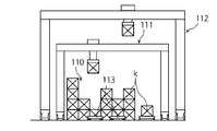
- a container terminal that includes a yard crane that moves in the longitudinal direction of the storage lane and separates and stores the container to be carried out and the container that has been carried in, as shown in FIG. And a container terminal provided with a large yard crane 112 straddling the yard crane 111. Since this container terminal can pass the yard crane 111 and the yard crane 112 without colliding, the container k can be efficiently arranged in the storage lane 110. However, since it is necessary to move the yard cranes 111 and 112 for a long distance, it takes much time. In addition, there is a problem that the manufacturing cost and the maintenance cost of the large yard crane 112 increase.
- the present invention has been made in view of the above problems, and its purpose is to shorten the moving distance of the yard crane and to carry the container loaded from the foreign chassis and loaded into the ship and unloaded from the ship. It is to provide a container terminal capable of improving the efficiency of cargo handling by efficiently arranging containers to be transported to a chassis in a storage lane and a control method therefor. In addition, it is to provide a container terminal that can reduce energy consumption and a control method thereof.
- the container terminal of the present invention for solving the above problems includes a plurality of quay cranes for handling containers with respect to a ship, a plurality of storage lanes for arranging containers at predetermined positions, and at least straddling each storage lane
- a container terminal comprising two yard cranes, a plurality of circular transport carriages for transporting containers to the quay crane and each of the yard cranes, and a plurality of foreign chassis for transporting containers to the outside of the container terminals, Adjacent to each of the storage lanes between one yard crane handling the circulatory carriage or the foreign chassis outside the end of the storage lane and the other yard crane handling the storage lane
- a reciprocating carriage that reciprocates in the longitudinal direction in the area to carry the container is provided.
- the circular transport carriage or the foreign chassis and the reciprocating carriage deliver the container via one yard crane outside the end of the storage lane, and the reciprocating carriage can carry the container to the other yard crane. it can.
- the reciprocating carriage for transporting containers in the storage lane area, the moving distance (traveling distance) of the yard crane can be shortened, and the time required for cargo handling work can be shortened.
- energy consumption can be suppressed by shortening the moving distance (traveling distance) of the yard crane and transporting the container with a reciprocating carriage that is lighter and consumes less energy.
- the container terminal includes a first delivery area for delivering containers between the orbiting carriage and the reciprocating carriage via a first yard crane that handles the orbiting carriage, and the foreign chassis.
- a second delivery area for delivering the container between the reciprocating carriage and the foreign chassis via a second yard crane that handles the cargo, and the reciprocating carriage is formed by an unmanned conveyance carriage, A reciprocating path that connects the delivery area and the second delivery area is provided.
- the reciprocating carriage can move to the first delivery area and the second delivery area, and the first or second crane hardly moves, and the orbiting carriage or the foreign chassis to the reciprocating carriage, or The container can be passed from the reciprocating carriage to the round conveyance carriage or the foreign chassis. Therefore, the moving distance of the yard crane can be further suppressed.
- the travel distance of the circular conveyor cart is reduced, and at the same time, the number of the circular conveyor carts is reduced, and the cost is lower than that of the circular conveyor cart. Cost can be reduced by using a reciprocating carriage. Moreover, safety is increased by providing the second delivery area for handling the foreign chassis.
- the reciprocating carriage only needs to reciprocate in the longitudinal direction of the storage lane, and the manufacturing cost can be reduced as compared with the circulating conveyance carriage. Further, by forming the reciprocating path with rails, the control of the reciprocating carriage can be simplified. Therefore, it is possible to further reduce the cost for the reciprocating carriage.
- the container terminal is formed of an unmanned transport cart that switches back the circular transport cart, branches from a travel route that circulates in the quay apron region of the circular transport cart in the first delivery region, and the storage terminal A plurality of delivery paths extending to the end of the lane and substantially parallel to the round-trip path are provided.
- the plurality of delivery paths and the round-trip path of the reciprocating carriage can be provided substantially in parallel, and the first yard crane can straddle the delivery path, so that the circular conveyance performed in the first delivery area
- the delivery of containers between the carriage and the reciprocating carriage via the first yard crane can be made smooth. Since the delivery route and the reciprocating route are positioned substantially parallel to each other, it is possible to eliminate the need to change the direction when the container is placed on the orbiting transport carriage and the reciprocating carriage. Furthermore, since a plurality of orbital transport carts can be stopped directly below the first yard crane, the cargo handling efficiency for the ship can be increased.
- the container terminal is formed by an unmanned transport cart that switches back the circular transport cart, branches from a travel route that circulates in the quay apron region of the circular transport cart in the first delivery region, and the reciprocating route It is configured with a shared route extending to
- the first yard crane winds up the container with the lifting tool, and after the orbiting carriage retreats from directly below the yard crane, the reciprocating carriage is the first. It stops just below the yard crane, and the first yard crane can unload the container with a lifting device. Therefore, there is no traversing of the trolley of the first yard crane, it is possible to shorten the time required for the delivery of the container via the yard crane between the circular conveyance carriage and the reciprocating carriage, and to simplify the operation of the first yard crane. .
- the container terminal control method of the present invention for achieving the above object includes a plurality of quay cranes for handling containers with respect to a ship, a plurality of storage lanes for arranging containers at predetermined positions, and the storage lanes.
- a container terminal comprising: at least two yard cranes straddling a plurality of terrain cranes; a plurality of circular transport carriages for transporting containers to the quay cranes and the yard cranes; and a plurality of foreign chassis for transporting containers to the outside of the container terminals
- this control method outside the end of each storage lane, one yard crane handles the circulatory carriage or the foreign chassis, and the other yard crane loads the container at a predetermined position in the storage lane.
- the reciprocating carriage that loads and reciprocates in the longitudinal direction in the adjacent area of each storage lane is each yard. Transporting the container to the lane.
- the transport distance of the container by the yard crane whose movement speed is slower than that of the reciprocating carriage can be shortened, and the shortened container can be transported by the reciprocating carriage having a movement speed faster than that of the yard crane. Therefore, the cargo handling efficiency of the container terminal can be increased.
- the reciprocating carriage consumes less energy. Therefore, energy consumption can be suppressed by transporting the container with a round-trip cart instead of the yard crane.
- the container terminal control method may be configured such that when a container is unloaded from the ship or the foreign chassis to the storage lane, one yard crane is disposed outside the end of the storage lane, and A container is passed from the foreign chassis to the reciprocating carriage, the reciprocating carriage conveys the container to the other yard crane, the other yard crane arranges the container in the storage lane, and the ship or the foreign
- one yard crane passes the container from the storage lane to the reciprocating carriage
- the reciprocating carriage conveys the container to the other yard crane, outside the end of the storage lane
- the other yard crane is connected from the reciprocating carriage to the orbiting carriage or the foreign chassis. Passing the container.
- the orbiting carriage that received the containers from the quay crane stops at the first delivery area outside the end of the storage lane and is placed on the spot.
- the one-yard crane receives the container and passes it to the round-trip carriage.
- the reciprocating cart that has received the container travels in an adjacent area of the storage lane and transports the container to a second yard crane arranged at a position for storing the container on the storage lane.
- the second yard crane can place the container at a predetermined position in the storage lane.
- the second yard crane When carrying a container from the foreign chassis, the foreign chassis stops in the second delivery area outside the end of the storage lane, the second yard crane receives the container, and passes the container to the round-trip carriage.
- the carriage that has received the container transports the container to the first yard crane that is disposed at a position to store the container.
- the first yard crane can place the container at a predetermined position in the storage lane.
- one yard crane passes the container from a predetermined position in the storage lane to the reciprocating carriage, and the reciprocating carriage is placed outside the end of the storage lane. Transport the container to the other yard crane.
- the yard crane can pass the container to the orbiting carriage or the foreign chassis. Therefore, by reducing the moving distance of a yard crane with a slow moving speed as much as possible and transporting the container by using a reciprocating carriage that reciprocates the adjoining storage lane, the container handling work can be efficiently performed. .
- energy consumption by increasing cargo handling efficiency can be suppressed, and container transportation by a yard crane can be reduced, and the amount of energy consumed can be further suppressed by a reciprocating carriage.
- containers placed in the storage lane are placed on the sea side of the storage lane, and containers loaded from the ship are placed on the land side of the storage lane.
- the best handling efficiency when placed it is possible to make the arrangement of the containers in the storage lane the most efficient arrangement while reducing the moving distance of the yard crane as much as possible.
- the moving distance of the yard crane can be shortened, and the container is received from the storage lane to the quay crane and the foreign chassis. Since the moving distance of the yard crane can be shortened also when handing over, the cargo handling efficiency of the container terminal can be increased. In addition, it is possible to reduce the energy consumption of the container terminal by increasing the cargo handling efficiency of the container terminal and reducing the power consumption by reducing the container transportation by the yard crane.
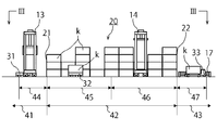
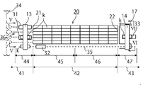
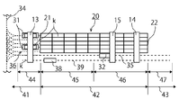
- FIG. 1 is a plan view showing a container terminal according to a first embodiment of the present invention.
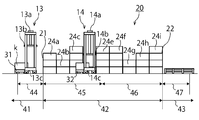
- FIG. 2 is a view taken along the line II-II in FIG.
- FIG. 3 is a view taken along the line III-III in FIG.
- FIG. 4 is an enlarged view of the seaside delivery area (first delivery area) 44 of FIG.
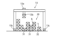
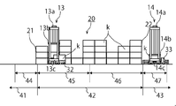
- FIG. 5 is a view taken along the line VV in FIG. 6 is a view taken in the direction of arrow VI-VI in FIG.
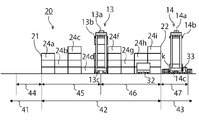
- FIG. 7 is an arrow view showing the operation of loading / unloading containers from a ship in II-II of FIG.
- FIG. 8 is an arrow view showing the operation of loading a container from the foreign chassis in II-II of FIG.
- FIG. 1 is a plan view showing a container terminal according to a first embodiment of the present invention.
- FIG. 2 is a view taken along the line II-II in FIG.
- FIG. 3 is a view taken along the line III-III in FIG.
- FIG. 9 is an arrow view showing an operation of loading a container on a ship in II-II of FIG.
- FIG. 10 is an arrow view showing the operation of carrying out the container to the foreign chassis in II-II of FIG.
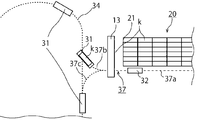
- FIG. 11 is an enlarged view showing a part of the container terminal according to the second embodiment of the present invention.
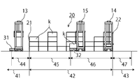
- FIG. 12 is a view showing a container terminal according to a third embodiment of the present invention.
- FIG. 13 is a view showing a container terminal according to the fourth embodiment of the present invention.
- FIG. 14 is a front view showing a part of a conventional container terminal.
- the container terminal 10 includes a ship 11 that comes in contact with the quay 1, three quay cranes 12 that unload a container k against the ship 11,
- the storage lane 20 has a longitudinal direction in the sea-land direction or a direction orthogonal to the traveling direction of the quay crane 12 (the transverse direction of the quay crane 12), and the container k is disposed at a predetermined position.
- six storage lanes having a longitudinal direction in the transverse direction of the quay crane 12 are used, but depending on the container terminal 10, a storage lane having a longitudinal direction in the traveling direction of the quay crane 12 may be used. It can be the number of lanes.
- the container terminal 10 includes a quay apron area 41 on the most sea side, a storage area 42 in which the storage lane 20 is installed, and a gate yard 43.
- a quay crane 12 and a travel route 34 of the orbiting transport carriage 31 are provided in the quay apron region 41.
- the quay crane 12 loads and unloads the container k with respect to one ship 11 by hoisting and lowering the suspension and reciprocating the trolley in the transverse direction (sea and land direction).
- the container k is an ISO standard container having a width of 8 feet, a height of 8 feet, a length of 20 feet or 40 feet, but may be a container of other standards.
- the orbiting transport cart 31 is formed of an unmanned transport cart (hereinafter referred to as AGV) that passes through each quay crane 12 and travels on a travel route 34 that circulates in the quay apron region 41 in an annular shape.
- AGV unmanned transport cart
- the circular transport carriage 31 is not limited to AGV but may be manned, but AGV is suitable in terms of efficiency.
- the travel path 34 is formed by embedding a magnetic tape or the like, and the traveling carriage 31 detects the magnetic tape with a sensor so that the travel direction is selected without departing from the travel path 34 or by branching or crossing. Even in this case, the traveling direction can be controlled. Further, the circular transport carriage 31 is formed so as to be capable of switchback traveling.
- the circumferential transport cart 31 only circulates around the quay apron region 41 in an annular shape, so that the travel distance is shortened to each stage compared to the conventional case, and failure or the like is unlikely to occur, and the maintenance cost can be suppressed.
- the circular transport carriage 31 is not particularly limited to the above configuration, and may be anything that can transport the container k.
- a first yard crane 13 hereinafter referred to as a sea-side yard crane 13
- a second yard crane 14 hereinafter referred to as a land-side yard crane 14
- a reciprocating carriage 32 capable of reciprocating in the longitudinal direction of the storage lane 20 in an area adjacent to each storage lane 20, and a reciprocating path 35 thereof And provide.
- the gate yard 43 is provided with a control system for controlling at least the unmanned circulatory carriage 31 and the reciprocating carriage 32, and instructed to the manned quay crane 12, the sea yard crane 13, the land yard crane 14 and the foreign chassis 33.
- Management building 15 and gate 16 serving as an entrance to the outside.
- Reference numeral 33 denotes an external chassis 33.
- the storage lane 20 includes a first end 21 (hereinafter referred to as sea-side end 21) and a second end 22 (hereinafter referred to as land-side end 22).
- a first delivery area 44 (hereinafter referred to as a sea-side delivery area 44) is provided in an area in contact with the sea-side end portion 21 of the quay apron area 41, and a storage container for storing the storage area 42 mainly containing containers from the sea side.
- An area 45 and a carry-out container area 46 for storing containers mainly carried out from the land side are provided, and a second delivery area 47 (hereinafter referred to as a land-side delivery area 47) is provided in an area in contact with the land side end 22 of the gate yard 43 Is provided).
- the sea-side delivery area 44 is an area where the orbiting transport carriage 31 and the reciprocating carriage 32 deliver the container k via the sea-side yard crane 13.
- the land-side delivery area 47 is an area where the carriage 32 and the foreign chassis 33 deliver the container k via the land-side yard crane 14.
- the orbiting carriage 31 has been designated adjacent to the storage lane 20, for example, traveling adjacent to the storage lane 20 up to the yard cranes 13 and 14 of the storage lane 20. Therefore, when the container k is transported to the vicinity of the land side end portion 22 of the storage lane 20, the traveling distance of the circular transport carriage 31 is long, and since it returns to each quay crane 12 after reciprocating the storage lane 20, It took time. In order to eliminate the decrease in cargo handling efficiency due to the time required, the number of the circular transport carts 31 has been increased.
- the orbiting carriage 31 can deliver the container k in the sea-side delivery area 44, immediately return to the travel path 34, and transport the container k from the quay crane 12 again. And loading and unloading of the container k of the ship 11 can be performed. Therefore, since the travel distance of the circular conveyance cart 31 can be reduced, the number of the circular conveyance carts 31 that are costly can be reduced and the cost for maintaining the same can also be reduced. In order to transport the container k between the yard cranes 13, 14, a round-trip carriage 32 must be provided, but the round-trip carriage 32 only needs to be able to reciprocate adjacent to the storage lane 20. The structure is simple and the cost can be reduced.
- the manned foreign chassis 33 is loaded by the land-side yard crane 14 in the land-side delivery area 47 provided outside the land-side end 22 of the storage lane 20, so the manned foreign chassis 33 enters the storage area 42. I will not let you. In particular, since the container k and the land-side yard crane 14 do not pass directly above the driver's seat where the driver is located, safety is improved.
- the carry-in container area 45 is an area in which the container k into which the foreign chassis 33 is carried from the outside of the container terminal 10 and loaded into the ship 11 is arranged.
- the carry-out container area 46 is an area in which a container k that is unloaded from the ship 11 and is carried out by the foreign chassis 33 to the outside of the container terminal 10 is arranged.
- the cargo handling efficiency is further improved by roughly separating the storage lane 20 on the sea side into the carry-in container area 45 and the land side on the carry-out container area 46.
- this distinction is a rough distinction and is not limited to the above configuration.
- containers can be stored without distinction in the case of a hub port that handles cargo from ship to ship.
- the round trip path 35 of the round trip cart 32 connects the sea side delivery area 44 and the land side delivery area 47 in the adjacent area of the storage lane 20.
- the reciprocating path 35 may be formed of a magnetic tape
- the reciprocating carriage 32 may be formed in a rail shape because it only travels back and forth.
- the reciprocating carriage 32 is also formed of AGV as with the orbiting conveyance carriage 31, but the performance equivalent to that of the orbiting carriage 31 is not required.
- the reciprocating carriage 32 includes a wheel that can run on the rail and a motor that can control forward / reverse rotation or a mechanism that normally rotates the motor and controls the wheel forward / reversely. Compared with the carriage 31, the manufacturing cost is low.
- the delivery route 36 of the circular transport carriage 31 provided in the sea side delivery region 44 branches from the travel route 34 and extends to the sea side end 21.
- the delivery path 36 includes a stop path 36a where the circular conveyance carriage 31 stops, an entry path 36b which allows the circular conveyance carriage 31 to enter the stop path 36a from the travel path 34, and a circular conveyance carriage 31 which switches from the stop path 36a. It consists of an escape path 36 c that allows the vehicle to travel back and escape to the travel path 34.
- the delivery path 36 may be formed only by the stop path 36 a extending to the travel path 34.
- the circular transport carriage 31 is controlled to stop on the stop path 36a so that the seaside yard crane 13 that delivers the container k does not move one by one.
- the sea side yard crane 13 is provided so as to straddle the storage lane 20 and the travel route 34 of the reciprocating carriage 32. Further, in the sea-side delivery area 44, the sea-side yard crane 13 straddles a plurality of circular transport carriages 31 and the reciprocating carriage 32.
- the sea-side yard crane 13 includes a traversing trolley 13a, a lifting tool 13b, and a traveling device 13c for moving on the storage lane 20.
- the plurality of orbiting transport carts 31 can transport the container k to the sea-side delivery area 44 and transport them one by one in order. Rather than efficiently. Further, the circular transport carriage 31 and the reciprocating carriage 32 do not wait for each other's operation.
- the configuration of the land side yard crane 14 is the same as that of the sea side yard crane 13. Since the foreign chassis 33 is manned, the safety fence 17 is provided so as not to enter the area where the land-side yard crane 14 and the reciprocating carriage 32 travel in consideration of safety. By providing the safety fence 17, the manned foreign chassis 33 does not enter the storage area 42, and an accident such as a collision with the land-side yard crane 14 or the reciprocating carriage 32 can be prevented. In addition, since the area where the container terminal 10 operates unattended and the area where the container terminal 10 operates unmanned are distinguished, automation can be further promoted in the area where the container terminal 10 operates unattended.
- At least the circulating carriage 31 and the reciprocating carriage 32 are controlled so as to operate automatically, and the control is performed by the computer of the management building 15 provided in the gate yard 41. Yes.
- FIG. 7 shows the operation of loading and unloading the container k from the ship 11 to the storage lane 20 using the circular transport carriage 31, and
- FIG. 8 shows the operation of loading the container k from the foreign chassis 33 to the storage lane 20.
- FIG. 9 shows the operation of loading the container k into the ship 11 using the circular transport carriage 31, and
- FIG. 10 shows the operation of carrying out the container k from the storage lane 20 to the foreign chassis 33.
- the sea-side yard crane 13 moves to the sea-side delivery area 44 and waits before the orbiting carriage 31 stops on the delivery path 36. Moreover, the sea side yard crane 13 moves the trolley 13a to the stop position of the orbiting conveyance carriage 31 so that the container k can be picked up at the position where the orbiting conveyance carriage 31 stops. Then, at the same time as the circular conveyance carriage 31 is stopped, the suspension tool 13b is lowered, the container k is grasped by the suspension tool 13b, and the container k is wound up. The orbiting carriage 31 that has passed the container k to the seaside yard crane 13 performs switchback traveling, returns to the traveling path 34, and recirculates to receive the container k from the quay crane 12.
- the round-trip carriage 32 returns to the seaside delivery area 44 and stops.
- the sea side yard crane 13 traverses the trolley 13a to a position directly above the reciprocating carriage 32, lowers the suspension 13b, and passes the container k to the reciprocating carriage 32.
- the reciprocating carriage 32 that has received the container k travels on the reciprocating path 35 and travels to the land-side yard crane 14 that is standing by at a designated position in the carry-out area 46 where the container k is disposed.
- the land-side yard crane 14 is waiting by moving the trolley 14a to a position where the reciprocating carriage 32 stops.
- the land-side yard crane 14 lowers the suspension 14b at the same time as the reciprocating carriage 32 stops, grips the container k, and raises the container k.
- the round-trip cart 32 that has transferred the container k to the land-side yard crane 14 returns to the sea-side delivery area 44.
- the land-side yard crane 14 that has wound up the container k traverses the trolley 14 a and stops it at a specified position, lowers the hanger 14 b, and places the container k at a predetermined position in the storage lane 20. This completes the operation of loading and unloading the container k from the ship 11. This operation is performed for all the designated containers k of the ship 11.
- the operation of carrying the container k from the foreign chassis 33 to the storage lane 20 is to replace the circulating carriage 31 in the above operation with the foreign chassis 33, exchange the roles of the sea side yard crane 13 and the land side yard crane 14, and The operation is the same when the area for transfer to and from the round-trip carriage 32 is changed to the sea-side transfer area 44 and the land-side transfer area 47.
- the container k unloaded from the ship 11 can be arranged on the land side of the storage lane 20 so that it can be easily carried out to the foreign chassis 33, and each yard crane 13, 14 is operated during the operation. Since the movement of the vehicle can be reduced, cargo handling efficiency can be increased. On the contrary, the container k carried in from the foreign chassis 33 can be arranged near the sea side of the storage lane 20 so that it can be easily loaded on the ship 11.
- the orbiting carriage 31 has a role of transporting the container k in the quay apron region, one of the sea side yard crane 13 and the land side yard crane 14 has a role of delivery of the container k, and the other has an arrangement of the container k.
- Role, reciprocating carriage 32 is used to transport container k between yard cranes, and external chassis 33 is used to carry out to the outside. Efficiency can be realized.
- the sea side yard crane 13 is moved to the sea side delivery area 44 and made to stand by, and the land side yard crane 14 is moved from the land side of the carry-in container area 45 and made to stand by.
- the distance between the container k loaded on the ship 11 and the sea side yard crane 13 is calculated, and if the distance is within a predetermined range, the sea side yard crane 13 moves to the carry-in container area 45 and grabs the container k. It is transported to the circular transport cart 31. If the distance exceeds a certain range, the land-side yard crane 14 delivers the container k to the reciprocating carriage 32, and the reciprocating carriage 32 carries the sea-side yard crane 13.
- the circular transport cart 31 that has received the container k switches back on the delivery path 36, returns to the travel path 34, transports the container k to the quay crane 12, and the quay crane 12 loads the container k onto the ship 11. Thus, loading of the container k into the ship 11 is completed.
- the predetermined range is, for example, the middle container row 24c in the carry-in container area 45 of the storage lane 20 shown in FIG.
- the sea side yard crane 13 moves to the container row 24a, grabs the container k, returns to the sea side delivery area 44, and passes the container k to the circulating transport cart 31.
- the land-side yard crane 14 moves to the container row 24e, passes the container k to the reciprocating carriage 32, and the reciprocating carriage 32 reaches the sea-side yard crane 13.
- Transport container k is, for example, the middle container row 24c in the carry-in container area 45 of the storage lane 20 shown in FIG.
- the predetermined range is not limited to the above.
- the working time required when the reciprocating carriage 32 is used or not used may be calculated in advance, and the working time may be used as a basis.
- the container k arranged in the carry-out container area 46 of the storage lane 20 is carried out to the foreign chassis 33. As shown in FIG. If the role of the yard crane 14 is reversed and the orbiting carriage 31 is replaced with the foreign chassis 33, the same method is used.
- the transportation by the yard cranes 13 and 14 is selected, the distance of the container k is long, and the round trip is performed.
- the carriage 32 can finish the work in a shorter time, it is possible to select transportation by the other yard crane 13 or 14 and the reciprocating carriage 32, so that the cargo can be efficiently handled. it can.
- a shared route 37 is provided instead of the delivery route 36 provided in the seaside delivery region 44 of the container terminal 10 having the above-described configuration and the round-trip route 35 on which the round-trip carriage 32 travels.
- the shared path 37 includes a round-trip path 37a extending between the sea-side delivery area 44 and the land-side delivery area 45, and an approach path 37b that allows the circular transport carriage 31 to enter the round-trip path 37a from the travel path 34. And an evacuation path 37c that enables the circulatory carriage 31 to switch back from the round-trip path 37a and to escape to the travel path 34.
- the round trip path 37a is formed so that the round trip carriage 32 can travel.
- Rotating conveyance cart 31 carries container k, and sea side yard crane 13 winds up container k. Thereafter, the revolving carriage 31 switches back and travels back to the travel path 34. At the same time, the reciprocating carriage 32 enters under the sea side yard crane 13 and passes the container k from the sea side yard crane 13 to the reciprocating carriage 32.
- the sea side yard crane 13 delivers the container k only by the lifting and lowering operation of the lifting tool 13b. be able to. Therefore, it is not necessary to traverse the trolley 13a, thereby shortening the work time and reducing energy consumption as much as the trolley 13a is not traversed.
- an intermediate yard crane 15 is provided between the sea side yard crane 13 and the land side yard crane 14 in the storage lane 20 as shown in FIG.
- the land side yard crane 14 and the intermediate yard crane 15 are made to stand by in the carry-out container area 46 and the container k is closer to the position when the container k is placed at a predetermined position. Therefore, the cargo handling efficiency can be further increased.
- FIG. 13 As a fourth embodiment according to the present invention, as shown in FIG. 13, another reciprocation path 39 is provided adjacent to the storage lane 20 and next to the reciprocation path 35 in the above configuration.
- the reciprocating carriage 38 is caused to travel. Since the container k can be transported by the two carriages 32 and 38, the cargo handling efficiency can be increased.
- the container terminal 10 of the present invention is not limited to the above configuration, and for example, another six storage lanes may be provided on the land side of the storage lane 20.
- the traveling path 34 of the circular transport carriage 31 is formed so as to go around the storage lane 20, and the container is transported to the sea-side delivery area of the land-side storage lane.
- a round-trip carriage that can reciprocate between the sea-side storage lane and the land-side storage lane is provided, and the round-trip carriage that receives the container in the sea-side delivery area of the sea-side storage lane transports the container to the land-side storage lane. May be.
- the storage lane 20 may be formed to have a longitudinal direction in a direction substantially parallel to the quay. Even in that case, the storage lanes may be arranged so that the first delivery areas 44 or the second delivery areas 47 of the storage lanes 20 are aligned. Furthermore, the longitudinal direction of each storage lane 20 may face a plurality of directions.
- the control system for the container terminal 10 is performed by a personal computer in the management building 15 and controls the entire container terminal 10. It controls the automatic operation of the circular transport carriage 31 and the reciprocating carriage 32, and also performs linked control of the respective operations.
- the yard cranes 13 and 14 and the quay crane 12 are automated, the quay apron region 41 and the storage region 42 can be completely unmanned.
- the control system also manages each container k arranged in the storage lane 20. Each device can be instructed to stack containers k in the order of loading and unloading.
- the container terminal of the present invention reduces the movement of the yard crane as much as possible when handling the container, and instead transports the container with a reciprocating carriage, so that it is possible to increase the handling efficiency and suppress the consumption of energy. Therefore, it can be installed on a quay or the like and used as a base for marine transportation and land transportation.
Landscapes
- Warehouses Or Storage Devices (AREA)
Abstract
ヤードクレーンの移動を極力減らし、荷役効率を上げるコンテナターミナルとその制御方法を提供する。蔵置レーン20の一方の端部の外側に第1受渡領域44ともう一方の端部の外側に第2受渡領域47とを設け、第1受渡領域44で周回搬送台車31と往復台車32とが第1ヤードクレーン13を介してコンテナkの受け渡しを行うとき、往復台車32が第2ヤードクレーン14へコンテナkを運搬し、第2ヤードクレーン14が蔵置レーン20の搬出コンテナ領域46で荷役し、第2受渡領域47で外来シャーシ33と往復台車32とが第2ヤードクレーン14を介してコンテナkの受け渡しを行うとき、往復台車32が海側ヤードクレーン13へコンテナkを運搬し、第1ヤードクレーン13が蔵置レーン20の搬入コンテナ領域45で荷役するように構成された。
Description
本発明は、コンテナターミナルにおいて、蔵置レーンを跨ぐヤードクレーンの移動距離を短くして荷役効率を高めると共に、エネルギーの消費を抑えたコンテナターミナルと制御方法に関する。
コンテナターミナルは船舶に対してコンテナを積み込み又は積み卸し、陸上輸送用の外来シャーシでコンテナを搬入および搬出する施設である。また、積み卸し又は搬入されたコンテナを一時的に保管する施設でもある。
現在、国際航路におけるコンテナ輸送システムの急速な進展に伴い、コンテナターミナル内での荷役や蔵置作業の自動化や省力化が望まれている。すなわち船舶とコンテナターミナル間のコンテナの搬送およびコンテナターミナルでのコンテナの蔵置部分での自動化や高能率化、ならびに低コスト化などが重要になっている。
そこで、蔵置レーンを岸壁に対して略直交する向きに延在させ、蔵置レーン間をスイッチバック走行する無人搬送台車を備え、岸壁側と反対側にゲートを設けて外来シャーシとトランスファークレーン(ヤードクレーン)とが荷役を行う領域を設けたコンテナターミナルがある(例えば特許文献1参照)。このコンテナターミナルは、外来シャーシが蔵置領域に有人の外来シャーシが進入することがないため、蔵置面積率が上昇すると共に、コンテナターミナルを自動化することができた。
しかし、特に蔵置レーンに保管されたコンテナを外来シャーシへの搬出および外来シャーシから搬入して蔵置レーンに保管する際に、トランスファークレーン(ヤードクレーン)がコンテナを掴みながら蔵置レーン上を移動するため、荷役効率が悪くなるという問題がある。これはトランスファークレーン(ヤードクレーン)の移動速度が約18km/hと遅いためである。
また、特許文献1に記載のコンテナターミナルでは、船舶への積み込みおよび外来シャーシへの搬出が効率的に行えるように、コンテナを蔵置レーンに配置するには、やはりトランスファークレーン(ヤードクレーン)の移動距離を多くしなければならない。岸壁クレーンの走行方向と直交する方向、つまり海陸方向に延在する蔵置レーンを設ける場合、外来シャーシから搬入され、船舶へ積み込まれるコンテナを蔵置レーンの海側に配置し、船舶から積み卸しされて外来シャーシへ搬出されるコンテナを蔵置レーンの陸側に配置すると荷役効率は上がる。特許文献1に記載のコンテナターミナルでは特に外来シャーシへの搬出および搬入の際に、トランスファークレーン(ヤードクレーン)がコンテナを掴み上げ、蔵置レーンを走行するため、効率が落ちる。
さらに、トランスファークレーン(ヤードクレーン)がコンテナを吊って運搬する方法は荷役効率が悪く、そのため、無駄なエネルギーを消費しているという問題が発生する。
一方で、蔵置レーンの長手方向に移動するヤードクレーンを備え、搬出されるコンテナと搬入されたコンテナを区分して蔵置するコンテナターミナルにおいて、図14に示すように、蔵置レーン110を跨ぐヤードクレーン111と、そのヤードクレーン111を跨ぐ大きなヤードクレーン112を設けたコンテナターミナルがある。このコンテナターミナルはヤードクレーン111とヤードクレーン112とが衝突せずにすれ違うことができるため、蔵置レーン110で効率的にコンテナkを配置することができる。しかし、やはりヤードクレーン111および112を長距離移動させなければならないため、その分時間が掛かってしまう。加えて大型のヤードクレーン112の製造コストや維持コストが高くなるという問題も発生する。
本発明は、上記の問題を鑑みてなされたものであり、その目的は、ヤードクレーンの移動距離を短縮すると共に、外来シャーシから搬入され、船舶へ積み込まれるコンテナと、船舶から積み卸しされて外来シャーシへ搬出されるコンテナとを蔵置レーンに効率よく配置することで、荷役の効率化を図ることができるコンテナターミナルとその制御方法を提供することである。加えて、エネルギーの消費を抑えることができるコンテナターミナルとその制御方法を提供することである。
上記の問題を解決するための本発明のコンテナターミナルは、船舶に対してコンテナを荷役する複数の岸壁クレーンと、コンテナを所定の位置に配置する複数の蔵置レーンと、各該蔵置レーンを跨ぐ少なくとも2台のヤードクレーンと、前記岸壁クレーンと各前記ヤードクレーンとにコンテナを運搬する複数の周回搬送台車と、コンテナターミナルの外部にコンテナを運搬する複数の外来シャーシとを備えたコンテナターミナルにおいて、各前記蔵置レーンの端部の外側で前記周回搬送台車又は前記外来シャーシに対して荷役する一方のヤードクレーンと、各前記蔵置レーンで荷役する他方のヤードクレーンとの間を、各前記蔵置レーンに隣接する領域で長手方向に往復し、コンテナを運搬する往復台車を設けて構成される。
この構成によれば、蔵置レーンの端部の外側で周回搬送台車又は外来シャーシと往復台車とが一方のヤードクレーンを介してコンテナを受け渡し、往復台車が他方のヤードクレーンまでコンテナを運搬することができる。往復台車を蔵置レーンの領域でのコンテナの運搬に使用することでヤードクレーンの移動距離(走行距離)を短縮し、荷役作業に掛かる時間を短縮することができる。また、ヤードクレーンの移動距離(走行距離)を短くして、より重量が軽く消費エネルギーの少ない往復台車でコンテナを運搬させることでエネルギーの消費を抑えることができる。
また、上記のコンテナターミナルは、前記周回搬送台車に対して荷役する第1ヤードクレーンを介して前記周回搬送台車と前記往復台車との間でコンテナの受け渡しを行う第1受渡領域と、前記外来シャーシに対して荷役する第2ヤードクレーンを介して前記往復台車と前記外来シャーシとの間でコンテナの受け渡しを行う第2受渡領域とを設け、前記往復台車を無人搬送台車で形成し、前記第1受渡領域と前記第2受渡領域とを連絡する往復経路を設けて構成される。
この構成によれば、往復台車が第1受渡領域と第2受渡領域まで移動することができ、第1又は第2クレーンがほとんど移動することなく、周回搬送台車又は外来シャーシから往復台車へ、もしくは、往復台車から周回搬送台車又は外来シャーシへコンテナを渡すことができる。そのため、よりヤードクレーンの移動距離を抑えることができる。
周回搬送台車に対して第1ヤードクレーンが荷役する第1受渡領域を設けることで、周回搬送台車の走行距離を縮めると同時に、周回搬送台車の台数を削減し、周回搬送台車よりもコストの安い往復台車を用いることでコストを削減することができる。また、外来シャーシに対して荷役する第2受渡領域を設けることで、安全性が増す。
また、この構成によれば、往復台車は蔵置レーンの長手方向に往復するだけでよく、周回搬送台車よりも製造コストを抑えることができる。さらに往復経路をレールで形成することで、往復台車の制御を単純化することができる。そのため、往復台車に掛かるコストをさらに抑えることができる。
その上、上記のコンテナターミナルは、前記周回搬送台車をスイッチバック走行する無人搬送台車で形成し、前記第1受渡領域で前記周回搬送台車の岸壁エプロン領域を循環する走行経路から分岐し、前記蔵置レーンの端部まで延在し、前記往復路と略平行な複数の受渡経路を設けて構成される。
この構成によれば、複数の受渡経路と往復台車の往復路とを略平行に設けることができ、且つ第1ヤードクレーンが受渡経路を跨ぐことができるので、第1受渡領域で行われる周回搬送台車と往復台車との第1ヤードクレーンを介したコンテナの受け渡しを円滑にすることができる。受渡経路と往復経路とが略平行に位置することで、周回搬送台車と往復台車にコンテナを載せるときの向きを変える必要を無くすことができる。さらに、第1ヤードクレーンの直下に複数の周回搬送台車を停車させることができるため、船舶に対する荷役効率を高くすることができる。
もしくは、上記のコンテナターミナルは、前記周回搬送台車をスイッチバック走行する無人搬送台車で形成し、前記第1受渡領域で前記周回搬送台車の岸壁エプロン領域を循環する走行経路から分岐し、前記往復経路へと延長する共有経路を設けて構成される。
この構成によれば、周回搬送台車が第1ヤードクレーンの直下で停止し、第1ヤードクレーンがコンテナを吊り具で巻上げ、周回搬送台車がヤードクレーンの直下から退いたのち、往復台車が第1ヤードクレーンの直下に停止し、第1ヤードクレーンがコンテナを吊り具で巻下ろすことができる。そのため、第1ヤードクレーンのトロリの横行がなく、周回搬送台車と往復台車とのヤードクレーンを介したコンテナの受け渡しに掛かる時間を短縮し、且つ第1ヤードクレーンの操作を単純にすることができる。
上記の目的を達成するための本発明のコンテナターミナルの制御方法は、船舶に対してコンテナを荷役する複数の岸壁クレーンと、コンテナを所定の位置に配置する複数の蔵置レーンと、各該蔵置レーンを跨ぐ少なくとも2台のヤードクレーンと、前記岸壁クレーンと各前記ヤードクレーンとにコンテナを運搬する複数の周回搬送台車と、コンテナターミナルの外部にコンテナを運搬する複数の外来シャーシとを備えたコンテナターミナルの制御方法において、各前記蔵置レーンの端部の外側で、一方のヤードクレーンが前記周回搬送台車又は前記外来シャーシに対して荷役し、他方のヤードクレーンが前記蔵置レーンの所定の位置でコンテナを荷役し、各前記蔵置レーンの隣接する領域を長手方向に往復する前記往復台車が各前記ヤードクレーンにコンテナを運搬する。
この方法によれば、移動速度が往復台車に比べて遅いヤードクレーンによるコンテナの運搬距離を短縮し、ヤードクレーンよりも移動速度の速い往復台車でその短縮した分のコンテナの運搬を行うことができるため、コンテナターミナルの荷役効率を高めることができる。また、ヤードクレーンと往復台車とで消費されるエネルギーを比べたとき、往復台車の方がエネルギーの消費は少ない。そのため、ヤードクレーンの代わりに往復台車でコンテナを運搬することでエネルギーの消費を抑えることができる。
また、上記のコンテナターミナルの制御方法は、前記船舶又は前記外来シャーシから前記蔵置レーンへコンテナを荷役する際に、前記蔵置レーンの端部の外側で、一方のヤードクレーンが前記周回搬送台車又は前記外来シャーシから前記往復台車へとコンテナを渡し、前記往復台車が他方のヤードクレーンにコンテナを運搬し、前記他方のヤードクレーンが前記蔵置レーンにコンテナを配置し、前記蔵置レーンから前記船舶又は前記外来シャーシへコンテナを荷役する際に、前記蔵置レーンからコンテナを一方のヤードクレーンが前記往復台車へ渡し、前記往復台車が他方のヤードクレーンにコンテナを運搬し、前記蔵置レーンの端部の外側で、前記他方のヤードクレーンが前記往復台車から前記周回搬送台車又は前記外来シャーシへとコンテナを渡す。
この方法によれば、船舶からコンテナを積み卸す際には、岸壁クレーンからコンテナを受け取った周回搬送台車は蔵置レーンの端部の外側の第1受渡領域で停止し、その場に配置された第1ヤードクレーンがそのコンテナを受け取り、往復台車へコンテナを渡す。コンテナを受け取った往復台車は蔵置レーンの隣接する領域を走行し蔵置レーン上のそのコンテナを収める位置に配置された第2ヤードクレーンまでコンテナを運搬する。運搬されたコンテナを第2ヤードクレーンが蔵置レーンの所定の位置にコンテナを配置することができる。
外来シャーシからコンテナを搬入する際には、外来シャーシは蔵置レーンの端部の外側の第2受渡領域で停止し、第2ヤードクレーンがそのコンテナを受け取り、往復台車へそのコンテナを渡す。コンテナを受け取った往復台車はコンテナを収める位置に配置された第1ヤードクレーンまでコンテナを運搬する。運搬されたコンテナを第1ヤードクレーンが蔵置レーンの所定の位置にコンテナを配置することができる。
船舶への積み込みおよび外来シャーシへの搬出の際にも同様に、一方のヤードクレーンが蔵置レーンの所定の位置からコンテナを往復台車へ渡し、往復台車が蔵置レーンの端部の外側に配置された他方のヤードクレーンまで、コンテナを運搬する。そのヤードクレーンが周回搬送台車又は外来シャーシにコンテナを渡すことができる。よって、移動速度の遅いヤードクレーンの移動距離を極力少なくして、その分を蔵置レーンの隣接を往復する往復台車を使ってコンテナを運搬することで、コンテナの荷役作業を効率よくすることができる。加えて、荷役効率を上げることによるエネルギーの消費を抑えると共に、ヤードクレーンによるコンテナの運搬を減らし、その分を往復台車が行うことでエネルギーの消費をさらに抑えることができる。
加えて、船舶の積み込み又は積み卸しを考慮した場合、蔵置レーンに配置されるコンテナは蔵置レーンの海側に船舶に積み込むコンテナを配置し、蔵置レーンの陸側に船舶から積み卸しされたコンテナを配置するともっとも荷役効率がよい。上記の方法によれば、ヤードクレーンの移動距離を極力減少させた上で、蔵置レーンのコンテナの配置をもっとも効率のよい配置にすることができる。
本発明によれば、搬出および搬入に効率のよい位置にコンテナを蔵置レーンに配置する場合でも、ヤードクレーンの移動距離を短縮することができ、且つ蔵置レーンから岸壁クレーンおよび外来シャーシへコンテナを受け渡す際にもヤードクレーンの移動距離を短縮することができるため、コンテナターミナルの荷役効率を上げることができる。また、コンテナターミナルの荷役効率を上げることと、ヤードクレーンでのコンテナの運搬を減少させて消費電力を低くすることで、コンテナターミナルのエネルギーの消費を低く抑えることができる。
以下、本発明に係る実施の形態のコンテナターミナル10とコンテナターミナル10の制御方法について、図面を参照しながら説明する。
図1に示すように、本発明に係る第1の実施の形態のコンテナターミナル10は岸壁1に接岸する船舶11と、その船舶11に対してコンテナkを荷役する3台の岸壁クレーン12と、海陸方向もしくは岸壁クレーン12の走行方向と直交する方向(岸壁クレーン12の横行方向)に長手方向を持ち、コンテナkが所定の位置に配置されている蔵置レーン20とを備える。ここでは1例として岸壁クレーン12の横行方向に長手方向を持つ蔵置レーンを6レーンとしたが、コンテナターミナル10によっては、岸壁クレーン12の走行方向に長手方向を持つ蔵置レーンとしたり、また様々なレーン数にすることができる。さらに、岸壁クレーン12も1隻の船舶11に対して何台設置してもよく、船舶11も1隻とは限らない。コンテナターミナル10は一番海側の岸壁エプロン領域41と蔵置レーン20が設置される蔵置領域42とゲートヤード43とを備える。
岸壁エプロン領域41に、岸壁クレーン12と、周回搬送台車31の走行経路34とを設ける。岸壁クレーン12は1台の船舶11に対して、吊り具の巻上げ下げとトロリの横行方向(海陸方向)の往復によって、コンテナkの荷役を行う。コンテナkは幅8フィート、高さ8フィート、長さ20フィートまたは40フィートのISO規格コンテナであるが、それ以外の規格のコンテナでもよい。
周回搬送台車31は各岸壁クレーン12を通過して、岸壁エプロン領域41内を環状に周回する走行経路34上を走行する無人搬送台車(以下、AGVという)で形成されている。周回搬送台車31はAGVに限らず、有人のものでもよいが、効率面からAGVが適している。走行経路34は磁気テープなどを埋設して形成され、周回搬送台車31はその磁気テープをセンサーで検知することで走行経路34を外れることなく、また、分岐や交差などで進行方向が選択される場合であっても、その進行方向を制御することができる。さらに、周回搬送台車31はスイッチバック走行が可能なように形成されている。
周回搬送台車31は岸壁エプロン領域41を環状に周回するだけで、従来に比べると走行距離が各段に短縮され、故障等が発生しにくく維持コストを抑えることができる。周回搬送台車31は特に上記の構成に限らず、コンテナkを運搬できるものであればよい。
蔵置領域42に、複数の蔵置レーン20と、各蔵置レーン20を跨ぎ、その長手方向に往復可能な海側寄りに設けられた第1ヤードクレーン13(以下海側ヤードクレーン13という)と、陸側寄りに設けられた第2ヤードクレーン14(以下陸側ヤードクレーン14という)と、各蔵置レーン20に隣接する領域で蔵置レーン20の長手方向に往復可能な往復台車32と、その往復経路35とを設ける。
ゲートヤード43に、少なくとも無人の周回搬送台車31と往復台車32とを制御する制御システムを備え、且つ、有人の岸壁クレーン12と海側ヤードクレーン13と陸側ヤードクレーン14と外来シャーシ33に指示を送る管理棟15や、外部への出入り口になるゲート16とを設ける。また、33は外来シャーシ33を示す。
図2に示すように、蔵置レーン20は第1端部21(以下海側端部21という)と第2端部22(以下陸側端部22という)とを備える。岸壁エプロン領域41の海側端部21と接する領域に第1受渡領域44(以下海側受渡領域44という)を設け、蔵置領域42を海側よりの主に搬入されたコンテナを蔵置する搬入コンテナ領域45と、陸側よりの主に搬出されるコンテナを蔵置する搬出コンテナ領域46とを設け、ゲートヤード43の陸側端部22と接する領域に第2受渡領域47(以下陸側受渡領域47という)を設ける。
海側受渡領域44は、周回搬送台車31と往復台車32とが海側ヤードクレーン13を介してコンテナkの受け渡しを行う領域である。また、陸側受渡領域47は往復台車32と外来シャーシ33とが陸側ヤードクレーン14を介してコンテナkの受け渡しを行う領域である。
従来であれば、周回搬送台車31は蔵置レーン20の中から指定された、例えば蔵置レーン20の各ヤードクレーン13、14まで蔵置レーン20の隣接を走行していた。そのため、周回搬送台車31の走行距離が長く、特に蔵置レーン20の陸側端部22の近傍までコンテナkを運搬する際には、蔵置レーン20を往復してから各岸壁クレーン12に戻るため、時間が掛かっていた。時間が掛かることによる荷役効率の低下を解消するために周回搬送台車31の台数を増やしていた。
海側受渡領域44を設けることによって、周回搬送台車31はコンテナkの受け渡しを海側受渡領域44で行い、直ぐに走行経路34に戻り、再び岸壁クレーン12からコンテナkを運搬することができ、次々と船舶11のコンテナkの積み込みおよび積み卸しを行うことができる。そのため、周回搬送台車31の走行距離を少なくすることができるので、コストが掛かる周回搬送台車31の数を減らすと共に、その維持に掛かるコストも減らすことができる。各ヤードクレーン13、14の間でコンテナkを運搬するために往復台車32を設けなければならないが、往復台車32は蔵置レーン20の隣接を往復することができればよいため、周回搬送台車31よりも構造が単純でコストを抑えることができる。
また、有人の外来シャーシ33は蔵置レーン20の陸側端部22の外側に設けた陸側受渡領域47で陸側ヤードクレーン14によって荷役されるため、有人の外来シャーシ33を蔵置領域42へ進入させることがない。特に運転手のいる運転席の真上をコンテナkや陸側ヤードクレーン14が通過することがなくなるため、安全性が向上する。
搬入コンテナ領域45は、コンテナターミナル10の外部から外来シャーシ33が搬入し、船舶11へ積み込まれるコンテナkを配置する領域である。また、搬出コンテナ領域46は、船舶11から積み卸しされ、外来シャーシ33がコンテナターミナル10の外部へ搬出するコンテナkを配置する領域である。蔵置レーン20の海側を搬入コンテナ領域45と陸側を搬出コンテナ領域46とに大まかに区別して配置することでより荷役効率が上がる。ただし、この区別は大まかな区別であり、上記の構成には限らない。例えば、船舶から船舶へ荷役するハブ港湾の場合などは区別なくコンテナを蔵置することができる。
図3に示すように、往復台車32の往復経路35は、蔵置レーン20の隣接する領域の海側受渡領域44と陸側受渡領域47とを連絡する。往復経路35は磁気テープで形成してもよいが、往復台車32は往復走行しかしないため、レール状に形成してもよい。往復台車32も周回搬送台車31と同様にAGVで形成するが、周回搬送台車31と同等の性能は必要ない。往復台車32はレール上を走行できる車輪と、正逆転制御できるモータ又はモータを定常回転させ車輪を正逆制御する機構とを備え、往復運動を制御する装置で動作を制御するだけなので、周回搬送台車31と比較すると製造コストが安価になる。
海側受渡領域44に設けられた周回搬送台車31の受渡経路36は、図4に示すように、走行経路34から分岐して、海側端部21まで延在している。受渡経路36は周回搬送台車31が停止する停止路36aと、走行経路34から周回搬送台車31が停止路36aへの進入を可能にする進入路36bと、停止路36aから周回搬送台車31がスイッチバック走行して、走行経路34への脱出を可能にする脱出路36cとからなる。周回搬送台車31がスイッチバック走行せずに、縦横自在に走行できるように形成されれば、受渡経路36を走行経路34まで延在する停止路36aのみで形成してもよい。周回搬送台車31はコンテナkを受け渡す海側ヤードクレーン13がいちいち移動することがないように、停止路36aで停車するように制御されている。
図5に示すように、海側ヤードクレーン13は蔵置レーン20と往復台車32の走行経路34とを跨ぐように設けられている。また、海側受渡領域44において、海側ヤードクレーン13は複数の周回搬送台車31と往復台車32とを跨ぐ。海側ヤードクレーン13は横行するトロリ13aと吊り具13bと蔵置レーン20上を移動するための走行装置13cとを備える。
上記のように受渡経路36と海側ヤードクレーン13とを設けることで、複数台の周回搬送台車31がコンテナkを海側受渡領域44へと運搬することができ、1台ずつ順番に運搬するよりも、効率よく運搬することができる。また、周回搬送台車31と往復台車32とが互いの動作を待つことがない。
図6に示すように、陸側ヤードクレーン14の構成は海側ヤードクレーン13と同様である。そして、外来シャーシ33は有人であるため、安全性を考慮して、陸側ヤードクレーン14および往復台車32が走行する領域に進入しないように、安全柵17を設ける。安全柵17を設けることによって、有人の外来シャーシ33は蔵置領域42に進入することがなく、陸側ヤードクレーン14や往復台車32との衝突などの事故を防ぐことができる。加えて、コンテナターミナル10を無人で動作する領域と有人で動作させる領域とが区別されるため、無人で動作する領域ではより自動化を推し進めることが可能となる。
上記の構成のコンテナターミナル10の少なくとも周回搬送台車31と往復台車32とは自動で動作するように制御されており、その制御はゲートヤード41に設けられている管理棟15のコンピュータで行われている。
次に本発明の第1の実施の形態のコンテナターミナル10で行われるコンテナkの荷役動作を説明する。船舶11から周回搬送台車31を使って蔵置レーン20へコンテナkを積み卸す動作を図7に示し、外来シャーシ33から蔵置レーン20へコンテナkを搬入する動作を図8に示し、蔵置レーン20から船舶11へ周回搬送台車31を使ってコンテナkを積み込む動作を図9に示し、蔵置レーン20から外来シャーシ33へコンテナkを搬出する動作を図10に示す。
船舶11から周回搬送台車31を使って蔵置レーン20へコンテナkを積み卸す動作と、外来シャーシ33から蔵置レーン20へコンテナkを搬入する動作は周回搬送台車31と外来シャーシ33との違いになるため、ここでは図7に示す、積み卸し動作を説明する。
図7に示すように、周回搬送台車31が受渡経路36で停止する前に、海側ヤードクレーン13は海側受渡領域44に移動して待機している。また、海側ヤードクレーン13は周回搬送台車31が停止する位置でコンテナkをつかみ上げられるように、トロリ13aを周回搬送台車31の停車位置まで動かしておく。そして、周回搬送台車31が停止すると同時に、吊り具13bを巻下げ、コンテナkを吊り具13bがつかみ、コンテナkを巻上げる。コンテナkを海側ヤードクレーン13に渡した周回搬送台車31は、スイッチバック走行をして、走行経路34へと戻り、岸壁クレーン12からコンテナkを受け取るために再度、周回する。
上記の動作中又は動作完了するまでには、往復台車32が海側受渡領域44に戻って停車している。海側ヤードクレーン13はトロリ13aを往復台車32の真上の位置まで横行させ、吊り具13bを巻下げ、往復台車32へコンテナkを渡す。コンテナkを受け取った往復台車32は往復経路35上を走行し、搬出領域46内のコンテナkを配置する指定の位置で待機している陸側ヤードクレーン14まで走行する。陸側ヤードクレーン14は往復台車32が停止する位置へトロリ14aを移動させて待機している。
陸側ヤードクレーン14は、往復台車32が停止すると同時に吊り具14bを巻下げ、コンテナkを吊り具14bが掴み、コンテナkを巻上げる。コンテナkを陸側ヤードクレーン14へ渡した往復台車32は、海側受渡領域44へ戻っていく。コンテナkを巻上げた陸側ヤードクレーン14はトロリ14aを横行させ指定の位置で停止させ、吊り具14bを巻下げ、コンテナkを蔵置レーン20の所定の位置に配置する。以上で船舶11からコンテナkを積み卸しする動作が完了する。この動作を船舶11の指定されたコンテナk全てに対して行う。
外来シャーシ33から蔵置レーン20へコンテナkを搬入する動作は上記の動作の周回搬送台車31を外来シャーシ33へ換え、海側ヤードクレーン13と陸側ヤードクレーン14の役割を交換し、コンテナkの往復台車32との受け渡す領域を海側受渡領域44と陸側受渡領域47に換えると同様の動作になる。
上記の動作により、船舶11から積み卸しされたコンテナkを外来シャーシ33へ搬出しやすいように蔵置レーン20の陸側寄りに配置することができると共に、その作業の際に各ヤードクレーン13、14の移動を減らすことができるため、荷役効率を上げることができる。その逆で外来シャーシ33から搬入されたコンテナkを船舶11へ積み込みし易いように蔵置レーン20の海側寄りに配置することができる。
また、周回搬送台車31は岸壁エプロン領域でのコンテナkの運搬という役割、海側ヤードクレーン13又は陸側ヤードクレーン14のどちらか一方はコンテナkの受け渡しという役割、もう一方はコンテナkの配置という役割、往復台車32は各ヤードクレーン間でのコンテナkの運搬という役割、外来シャーシ33は外部への搬出という役割と、各装置に役割分担をはっきりさせることで制御を容易にし、且つ荷役の高効率を実現することができる。
次に、外来シャーシ33から蔵置レーン20へコンテナkを搬入する動作と、蔵置レーン20から船舶11へ周回搬送台車31を使ってコンテナkを積み込む動作を説明するが、海側ヤードクレーン13と陸側ヤードクレーン14の役割を逆にして、周回搬送台車31を外来シャーシ33に換えると同様の方法となるため、ここでは図9に示す、蔵置レーン20の搬入コンテナ領域45に配置されたコンテナkを船舶11に積み込む方法を説明する。
海側ヤードクレーン13を海側受渡領域44に移動して待機させ、陸側ヤードクレーン14を搬入コンテナ領域45の陸側よりに移動して待機させておく。船舶11へ積み込むコンテナkと海側ヤードクレーン13との距離を算出し、その距離が予め定められた範囲内であれば海側ヤードクレーン13が搬入コンテナ領域45へ移動してコンテナkを掴み、周回搬送台車31まで運搬する。距離が一定の範囲を超えれば陸側ヤードクレーン14がコンテナkを往復台車32へ渡し、往復台車32が海側ヤードクレーン13へ運搬する。コンテナkを受け取った周回搬送台車31は受渡経路36をスイッチバック走行し、走行経路34へ戻り、岸壁クレーン12へコンテナkを運搬し、岸壁クレーン12がコンテナkを船舶11へ積み込む。以上で船舶11へのコンテナkの積み込みが完了する。
上記の予め定められた範囲は、例えば、図9に示す、蔵置レーン20の搬入コンテナ領域45の真ん中のコンテナ列24cを範囲とする。その場合、コンテナ列24aのコンテナkを搬入する場合は、海側ヤードクレーン13がコンテナ列24aへ移動し、コンテナkを掴んで海側受渡領域44へ戻り、周回搬送台車31へコンテナkを渡す。一方、蔵置レーン20のコンテナ列24eのコンテナkを搬入する場合は、陸側ヤードクレーン14がコンテナ列24eへ移動し、コンテナkを往復台車32へ渡し、往復台車32が海側ヤードクレーン13までコンテナkを運搬する。そして、海側ヤードクレーン13を介して周回搬送台車31にコンテナkを渡す。この予め定められた範囲は上記に限らず、例えば、予め往復台車32を使用した場合と使用しない場合とで掛かる作業時間を算出しておき、その作業時間を元にしてもよい。
蔵置レーン20の搬出コンテナ領域46に配置されたコンテナkを外来シャーシ33に搬出する方法であるが、図10に示すように、上記の船舶11への積み込み方法の海側ヤードクレーン13と陸側ヤードクレーン14の役割を逆にして、周回搬送台車31を外来シャーシ33に換えると同様の方法となる。
上記の方法により、各ヤードクレーン13、14がコンテナkを運搬する方が短時間で作業を終えることができる場合は、各ヤードクレーン13、14による運搬を選び、コンテナkの距離が遠く、往復台車32が運搬する方が短時間で作業を終えることが出来る場合は、もう一方のヤードクレーン13又は14と往復台車32による運搬を選ぶことが可能になるため、効率的に荷役を行うことができる。
次に、本発明に係る第2の実施の形態のコンテナクレーン10について説明する。図11に示すように、上記の構成のコンテナターミナル10の海側受渡領域44に設けられる受渡経路36と往復台車32が走行する往復経路35とに替えて、共有経路37を設ける。共有経路37は、海側受渡領域44と陸側受渡領域45との間に延在する往復路37aと、走行経路34から周回搬送台車31が往復路37aへの進入を可能にする進入路37bと、往復路37aから周回搬送台車31がスイッチバック走行して、走行経路34への脱出を可能にする脱出路37cとからなる。また、往復路37aは往復台車32が走行できるように形成されている。
周回搬送台車31がコンテナkを運搬し、海側ヤードクレーン13がコンテナkを巻上げる。その後周回搬送台車31がスイッチバック走行し走行経路34に戻ると同時に往復台車32が海側ヤードクレーン13の下へ侵入し、海側ヤードクレーン13からコンテナkを往復台車32へ渡す。
上記の動作によれば、周回搬送台車31と往復台車32との走行する経路を一体に形成しているため、海側ヤードクレーン13が吊り具13bの巻上げ下げ動作のみでコンテナkの受け渡しを行うことができる。そのため、トロリ13aを横行させる必要がなくなり、その分作業時間を短縮すると共に、トロリ13aを横行させない分、エネルギーの消費を抑えることができる。
本発明に係る第3の実施の形態は、図12に示すように、蔵置レーン20に海側ヤードクレーン13と陸側ヤードクレーン14との間に中間ヤードクレーン15を設ける。例えば、船舶11からコンテナkを積み卸しするときに、陸側ヤードクレーン14と中間ヤードクレーン15とを搬出コンテナ領域46内に待機させ、コンテナkを所定の位置へ配置するときにより近い方が荷役することができるため、さらに荷役効率を上げることができる。
本発明に係る第4の実施の形態として、上記の構成に、図13に示すように、蔵置レーン20の隣接で往復経路35の隣にもう一本の往復経路39を設け、もう一台の往復台車38を走行させる。往復台車32と38の2台でコンテナkを運搬することができるため、荷役効率を上げることができる。
本発明のコンテナターミナル10は、上記のような構成に限らず、例えば、蔵置レーン20の陸側にもう6本の蔵置レーンを設けてもよい。その場合は周回搬送台車31の走行経路34が蔵置レーン20を周回するように形成し、陸側の蔵置レーンの海側受渡領域までコンテナを運搬するようにする。もしくは、海側の蔵置レーンと陸側蔵置レーンとを往復することができる往復台車を設け、海側蔵置レーンの海側受渡領域でコンテナを受け取った往復台車が陸側蔵置レーンまでコンテナを運搬してもよい。
また、蔵置レーン20を岸壁と略並行な方向に長手方向を持つように形成してもよい。その場合でも、各蔵置レーン20の各第1受渡領域44若しくは各第2受渡領域47同士が並ぶように各蔵置レーンを配置するとよい。さらに、各蔵置レーン20の長手方向が複数の方向を向いていてもよい。
上記のコンテナターミナル10の制御システムは、管理棟15のパソコンなどで行われ、コンテナターミナル10の全体の制御も行っている。周回搬送台車31と往復台車32の自動運転を制御し、また、それぞれの動作の連動制御も行う。加えて、各ヤードクレーン13、14および岸壁クレーン12を自動化すると岸壁エプロン領域41と蔵置領域42とが完全に無人化することもできる。
また、制御システムは蔵置レーン20に配置される1つ1つのコンテナkの管理も行っている。搬入および搬出される順番にコンテナkを積み上げるように各装置に指示を出すことができる。
本発明のコンテナターミナルは、コンテナを荷役する際に、ヤードクレーンの移動を極力減らし、代わりに往復台車でコンテナの運搬をするので、荷役効率を上げると共にエネルギーの消費を抑えることができる。そのため、岸壁などに設け、海上輸送と陸上輸送との拠点として用いることができる。
1 岸壁
10 コンテナターミナル
11 船舶
12 岸壁クレーン
13 海側ヤードクレーン
14 陸側ヤードクレーン
15 管理棟
16 ゲート
17 安全柵
20 蔵置レーン
21 海側端部
22 陸側端部
31 周回搬送台車
32 往復台車
33 外来シャーシ
34 走行経路
35 往復経路
36 受渡経路
37 共有経路
41 岸壁エプロン領域
42 蔵置領域
43 ゲートヤード
44 海側受渡領域
45 搬入コンテナ領域
46 搬出コンテナ領域
47 陸側受渡領域
10 コンテナターミナル
11 船舶
12 岸壁クレーン
13 海側ヤードクレーン
14 陸側ヤードクレーン
15 管理棟
16 ゲート
17 安全柵
20 蔵置レーン
21 海側端部
22 陸側端部
31 周回搬送台車
32 往復台車
33 外来シャーシ
34 走行経路
35 往復経路
36 受渡経路
37 共有経路
41 岸壁エプロン領域
42 蔵置領域
43 ゲートヤード
44 海側受渡領域
45 搬入コンテナ領域
46 搬出コンテナ領域
47 陸側受渡領域
Claims (8)
- 船舶に対してコンテナを荷役する複数の岸壁クレーンと、コンテナを所定の位置に配置する複数の蔵置レーンと、各該蔵置レーンを跨ぐ少なくとも2台のヤードクレーンと、前記岸壁クレーンと各前記ヤードクレーンとにコンテナを運搬する複数の周回搬送台車と、コンテナターミナルの外部にコンテナを運搬する複数の外来シャーシとを備えたコンテナターミナルにおいて、
各前記蔵置レーンの端部の外側で前記周回搬送台車又は前記外来シャーシに対して荷役する一方のヤードクレーンと、各前記蔵置レーンで荷役する他方のヤードクレーンとの間を、各前記蔵置レーンの隣接する領域を長手方向に往復し、コンテナを運搬する往復台車を設けたことを特徴とするコンテナターミナル。 - 前記周回搬送台車に対して荷役する第1ヤードクレーンを介して前記周回搬送台車と前記往復台車との間でコンテナの受け渡しを行う第1受渡領域と、前記外来シャーシに対して荷役する第2ヤードクレーンを介して前記往復台車と前記外来シャーシとの間でコンテナの受け渡しを行う第2受渡領域とを設け、
前記往復台車を無人搬送台車で形成し、前記第1受渡領域と前記第2受渡領域とを連絡する往復経路を設けたことを特徴とする請求項1に記載のコンテナターミナル。 - 前記蔵置レーンが海陸方向に長手方向を有し、
前記蔵置レーンの海側に、前記外来シャーシにより搬入されて前記船舶に積み込みされるコンテナを蔵置する搬入コンテナ領域と、前記蔵置レーンの陸側に、前記船舶から積み卸しされて前記外来シャーシが搬出するコンテナを蔵置する搬出コンテナ領域とを設けたことを特徴とする請求項1又は2に記載のコンテナターミナル。 - 前記周回搬送台車をスイッチバック走行する無人搬送台車で形成し、前記第1受渡領域で前記周回搬送台車の岸壁エプロン領域を循環する走行経路から分岐し、前記蔵置レーンの端部まで延在し、前記往復路と略平行な複数の受渡経路を設けたことを特徴とする請求項1~3のいずれか1項に記載のコンテナターミナル。
- 前記周回搬送台車をスイッチバック走行する無人搬送台車で形成し、前記第1受渡領域で前記周回搬送台車の岸壁エプロン領域を循環する走行経路から分岐し、前記往復経路へと延長する共有経路を設けたことを特徴とする請求項1~3のいずれか1項に記載のコンテナターミナル。
- 船舶に対してコンテナを荷役する複数の岸壁クレーンと、コンテナを所定の位置に配置する複数の蔵置レーンと、各該蔵置レーンを跨ぐ少なくとも2台のヤードクレーンと、前記岸壁クレーンと各前記ヤードクレーンとにコンテナを運搬する複数の周回搬送台車と、コンテナターミナルの外部にコンテナを運搬する複数の外来シャーシとを備えたコンテナターミナルの制御方法において、
各前記蔵置レーンの端部の外側で、一方のヤードクレーンが前記周回搬送台車又は前記外来シャーシに対して荷役し、他方のヤードクレーンが前記蔵置レーンの所定の位置でコンテナを荷役し、各前記蔵置レーンの隣接する領域を長手方向に往復する前記往復台車が各前記ヤードクレーンにコンテナを運搬することを特徴とするコンテナターミナルの制御方法。 - 前記船舶又は前記外来シャーシから前記蔵置レーンへコンテナを荷役する際に、前記蔵置レーンの端部の外側で、一方のヤードクレーンが前記周回搬送台車又は前記外来シャーシから前記往復台車へとコンテナを渡し、前記往復台車が他方のヤードクレーンにコンテナを運搬し、前記他方のヤードクレーンが前記蔵置レーンにコンテナを配置し、
前記蔵置レーンから前記船舶又は前記外来シャーシへコンテナを荷役する際に、前記蔵置レーンからコンテナを一方のヤードクレーンが前記往復台車へ渡し、前記往復台車が他方のヤードクレーンにコンテナを運搬し、前記蔵置レーンの端部の外側で、前記他方のヤードクレーンが前記往復台車から前記周回搬送台車又は前記外来シャーシへとコンテナを渡すことを特徴とする請求項6に記載のコンテナターミナルの制御方法。 - 海陸方向に長手方向を有する前記蔵置レーンの海側に、前記前記外来シャーシにより搬入されて前記船舶に積み込みされるコンテナを蔵置し、前記蔵置レーンの陸側に前記船舶から積み卸しされて前記外来シャーシが搬出するコンテナを蔵置することを特徴とする請求項6又は7に記載のコンテナターミナルの制御方法。
Priority Applications (1)
| Application Number | Priority Date | Filing Date | Title |
|---|---|---|---|
| US14/008,494 US9862557B2 (en) | 2011-03-28 | 2012-03-26 | Container terminal and control method therefor |
Applications Claiming Priority (2)
| Application Number | Priority Date | Filing Date | Title |
|---|---|---|---|
| JP2011069868A JP5793323B2 (ja) | 2011-03-28 | 2011-03-28 | コンテナターミナルとその制御方法 |
| JP2011-069868 | 2011-03-28 |
Publications (1)
| Publication Number | Publication Date |
|---|---|
| WO2012133283A1 true WO2012133283A1 (ja) | 2012-10-04 |
Family
ID=46931001
Family Applications (1)
| Application Number | Title | Priority Date | Filing Date |
|---|---|---|---|
| PCT/JP2012/057714 Ceased WO2012133283A1 (ja) | 2011-03-28 | 2012-03-26 | コンテナターミナルとその制御方法 |
Country Status (3)
| Country | Link |
|---|---|
| US (1) | US9862557B2 (ja) |
| JP (1) | JP5793323B2 (ja) |
| WO (1) | WO2012133283A1 (ja) |
Cited By (4)
| Publication number | Priority date | Publication date | Assignee | Title |
|---|---|---|---|---|
| CN109313736A (zh) * | 2016-03-21 | 2019-02-05 | 马士基码头公司 | 针对集装箱装卸设备的通信布置和通信方法 |
| CN110516894A (zh) * | 2018-05-22 | 2019-11-29 | 招商局国际信息技术有限公司 | 货场调度方法及装置 |
| CN114241799A (zh) * | 2021-12-30 | 2022-03-25 | 北京经纬恒润科技股份有限公司 | 车辆调度方法及装置 |
| CN117208589A (zh) * | 2023-10-23 | 2023-12-12 | 内蒙古电力勘测设计院有限责任公司 | 一种煤场进、出煤布置结构 |
Families Citing this family (13)
| Publication number | Priority date | Publication date | Assignee | Title |
|---|---|---|---|---|
| JP6138720B2 (ja) * | 2014-03-31 | 2017-05-31 | 三井造船株式会社 | コンテナターミナル及びコンテナターミナルの運用方法 |
| JP2015193435A (ja) * | 2014-03-31 | 2015-11-05 | 三井造船株式会社 | コンテナターミナル及びコンテナターミナルの運用方法 |
| FR3031828A1 (fr) * | 2015-01-15 | 2016-07-22 | Batterie Mobile | Procede de chargement/dechargement de conteneurs dans une installation portuaire. |
| ES2871674T3 (es) * | 2015-03-04 | 2021-10-29 | Shibakai Co Ltd | Procedimiento de manipulación de la carga |
| CN105417190B (zh) * | 2015-12-25 | 2017-10-27 | 上海振华重工(集团)股份有限公司 | 集装箱码头、集装箱装卸方法和集装箱集疏方法 |
| DK179085B1 (en) * | 2016-03-21 | 2017-10-16 | Apm Terminals Man Bv | Container handling equipment controller arrangement |
| JPWO2018155716A1 (ja) * | 2017-02-27 | 2019-06-27 | 丸市倉庫株式会社 | 情報処理装置 |
| WO2018231222A1 (en) * | 2017-06-14 | 2018-12-20 | Lydle Richard C | Shipping container handling systems and methods |
| JP6656567B2 (ja) * | 2017-10-23 | 2020-03-04 | 株式会社三井E&Sマシナリー | コンテナターミナル及びその運用方法 |
| CN108502552B (zh) * | 2018-05-16 | 2024-04-30 | 青岛港国际股份有限公司 | 一种集装箱码头自动化堆场 |
| CN108516357B (zh) * | 2018-05-16 | 2024-03-15 | 青岛港国际股份有限公司 | 自动化集装箱装卸码头 |
| JP6762017B2 (ja) * | 2018-11-28 | 2020-09-30 | 一般社団法人港湾荷役機械システム協会 | コンテナターミナルの運用方法 |
| CN113443450A (zh) * | 2021-07-19 | 2021-09-28 | 中交第四航务工程勘察设计院有限公司 | 一种水平运输交互式自动化集装箱码头及其装卸系统 |
Citations (2)
| Publication number | Priority date | Publication date | Assignee | Title |
|---|---|---|---|---|
| JP2005075537A (ja) * | 2003-08-29 | 2005-03-24 | Mitsubishi Heavy Ind Ltd | コンテナターミナル |
| JP2011093654A (ja) * | 2009-10-29 | 2011-05-12 | Japan Association Of Cargo-Handling Machinery Systems | コンテナターミナル |
Family Cites Families (14)
| Publication number | Priority date | Publication date | Assignee | Title |
|---|---|---|---|---|
| DE1798090C2 (de) * | 1968-08-21 | 1981-10-08 | Tax, Hans, 8000 München | Einrichtung zur Steuerung selbsttätig gelenkter Straßenfahrzeuge einer Container-Verladeanlage |
| ES391179A1 (es) * | 1970-06-24 | 1974-03-16 | Salzgitter A G | Procedimiento para descargar yno cargar barcos conteniendo unidades de carga, especialmente containers. |
| US4773807A (en) * | 1986-04-30 | 1988-09-27 | Harnischfeger Engineers, Inc. | High-speed automatic storage and retrieval system and apparatus therefor |
| US5540532A (en) * | 1993-11-12 | 1996-07-30 | Transact International, Inc. | Apparatus for marine cargo container handling and storage |
| US6190107B1 (en) * | 1999-01-27 | 2001-02-20 | John J. Lanigan, Sr. | High density narrow-profile storage system |
| DE19923813A1 (de) * | 1999-05-20 | 2000-12-07 | Mannesmann Ag | Umschlaganlage für Stückgut, insbesondere für ISO-Container |
| US7547173B2 (en) * | 2003-06-30 | 2009-06-16 | Kyong-Ja Jung | Method and apparatus for storing and transferring containers |
| WO2005087633A1 (ja) * | 2004-03-12 | 2005-09-22 | Mitsui Engineering & Shipbuilding Co., Ltd. | コンテナ検査荷役方法およびコンテナ検査荷役システム |
| PT1616822E (pt) * | 2004-07-06 | 2007-01-31 | Perpetuma | Um procedimento e um sistema para transferência de cargas |
| US20060045659A1 (en) * | 2004-08-04 | 2006-03-02 | Hubbard William B Sr | Buffered magazine method and system for loading and unloading ships |
| US8585347B2 (en) * | 2007-06-26 | 2013-11-19 | Mi-Jack Products, Inc. | Hub and distribution system |
| CN101229883A (zh) * | 2008-01-24 | 2008-07-30 | 上海振华港口机械(集团)股份有限公司 | 集装箱码头装卸系统 |
| US7972102B2 (en) * | 2008-07-24 | 2011-07-05 | Marine Terminals Corporation | Automated marine container terminal and system |
| US20110217150A1 (en) * | 2009-12-07 | 2011-09-08 | Toru Takehara | Container storage yard transporation system |
-
2011
- 2011-03-28 JP JP2011069868A patent/JP5793323B2/ja active Active
-
2012
- 2012-03-26 WO PCT/JP2012/057714 patent/WO2012133283A1/ja not_active Ceased
- 2012-03-26 US US14/008,494 patent/US9862557B2/en not_active Expired - Fee Related
Patent Citations (2)
| Publication number | Priority date | Publication date | Assignee | Title |
|---|---|---|---|---|
| JP2005075537A (ja) * | 2003-08-29 | 2005-03-24 | Mitsubishi Heavy Ind Ltd | コンテナターミナル |
| JP2011093654A (ja) * | 2009-10-29 | 2011-05-12 | Japan Association Of Cargo-Handling Machinery Systems | コンテナターミナル |
Cited By (5)
| Publication number | Priority date | Publication date | Assignee | Title |
|---|---|---|---|---|
| CN109313736A (zh) * | 2016-03-21 | 2019-02-05 | 马士基码头公司 | 针对集装箱装卸设备的通信布置和通信方法 |
| US11756143B2 (en) | 2016-03-21 | 2023-09-12 | Apm Terminals B.V. | Communication arrangement for a container handling equipment and communication method |
| CN110516894A (zh) * | 2018-05-22 | 2019-11-29 | 招商局国际信息技术有限公司 | 货场调度方法及装置 |
| CN114241799A (zh) * | 2021-12-30 | 2022-03-25 | 北京经纬恒润科技股份有限公司 | 车辆调度方法及装置 |
| CN117208589A (zh) * | 2023-10-23 | 2023-12-12 | 内蒙古电力勘测设计院有限责任公司 | 一种煤场进、出煤布置结构 |
Also Published As
| Publication number | Publication date |
|---|---|
| JP2012201482A (ja) | 2012-10-22 |
| JP5793323B2 (ja) | 2015-10-14 |
| US20140079513A1 (en) | 2014-03-20 |
| US9862557B2 (en) | 2018-01-09 |
Similar Documents
| Publication | Publication Date | Title |
|---|---|---|
| JP5793323B2 (ja) | コンテナターミナルとその制御方法 | |
| JP5676338B2 (ja) | コンテナターミナルとその制御方法 | |
| JP5755404B2 (ja) | コンテナターミナル | |
| JP5698051B2 (ja) | コンテナターミナルとその制御方法 | |
| JP5969095B2 (ja) | コンテナターミナルとその制御方法 | |
| KR101298895B1 (ko) | 컨테이너 터미널 시스템 | |
| JP4418195B2 (ja) | コンテナターミナル | |
| WO2020110349A1 (ja) | コンテナターミナルの運用方法 | |
| JP5953090B2 (ja) | コンテナターミナルとその制御方法 | |
| JP2019206426A (ja) | コンテナターミナルの運用方法 | |
| JP6138720B2 (ja) | コンテナターミナル及びコンテナターミナルの運用方法 | |
| JP6155217B2 (ja) | コンテナターミナル及びコンテナターミナルの運用方法 | |
| JP6234867B2 (ja) | コンテナターミナル及びコンテナターミナルの運用方法 | |
| JP5840853B2 (ja) | 岸壁クレーンを備えたコンテナターミナルとその制御方法 | |
| JP6038335B2 (ja) | コンテナターミナル、コンテナ荷役方法、および、クレーン数決定方法 | |
| JP6271323B2 (ja) | コンテナターミナル及びコンテナターミナルの運用方法 | |
| JP6113551B2 (ja) | コンテナターミナル及びコンテナターミナルの運用方法 | |
| JP6380839B2 (ja) | コンテナターミナル及びコンテナターミナルの運用方法 | |
| JP2013212884A (ja) | コンテナターミナルとその制御方法 | |
| JP5495277B2 (ja) | 自動倉庫システム | |
| JP2015193435A (ja) | コンテナターミナル及びコンテナターミナルの運用方法 | |
| JP2002362750A (ja) | コンテナターミナルシステム | |
| JP2013212890A (ja) | コンテナターミナルとその制御方法 | |
| JP2007223782A (ja) | コンテナターミナル |
Legal Events
| Date | Code | Title | Description |
|---|---|---|---|
| 121 | Ep: the epo has been informed by wipo that ep was designated in this application |
Ref document number: 12764161 Country of ref document: EP Kind code of ref document: A1 |
|
| NENP | Non-entry into the national phase |
Ref country code: DE |
|
| WWE | Wipo information: entry into national phase |
Ref document number: 14008494 Country of ref document: US |
|
| 122 | Ep: pct application non-entry in european phase |
Ref document number: 12764161 Country of ref document: EP Kind code of ref document: A1 |