WO2012133280A1 - コンテナターミナルとその制御方法 - Google Patents
コンテナターミナルとその制御方法 Download PDFInfo
- Publication number
- WO2012133280A1 WO2012133280A1 PCT/JP2012/057711 JP2012057711W WO2012133280A1 WO 2012133280 A1 WO2012133280 A1 WO 2012133280A1 JP 2012057711 W JP2012057711 W JP 2012057711W WO 2012133280 A1 WO2012133280 A1 WO 2012133280A1
- Authority
- WO
- WIPO (PCT)
- Prior art keywords
- carriage
- container
- reciprocating
- storage lane
- delivery
- Prior art date
- Legal status (The legal status is an assumption and is not a legal conclusion. Google has not performed a legal analysis and makes no representation as to the accuracy of the status listed.)
- Ceased
Links
Images




Classifications
-
- B—PERFORMING OPERATIONS; TRANSPORTING
- B65—CONVEYING; PACKING; STORING; HANDLING THIN OR FILAMENTARY MATERIAL
- B65G—TRANSPORT OR STORAGE DEVICES, e.g. CONVEYORS FOR LOADING OR TIPPING, SHOP CONVEYOR SYSTEMS OR PNEUMATIC TUBE CONVEYORS
- B65G63/00—Transferring or trans-shipping at storage areas, railway yards or harbours or in opening mining cuts; Marshalling yard installations
- B65G63/002—Transferring or trans-shipping at storage areas, railway yards or harbours or in opening mining cuts; Marshalling yard installations for articles
- B65G63/004—Transferring or trans-shipping at storage areas, railway yards or harbours or in opening mining cuts; Marshalling yard installations for articles for containers
Definitions
- the present invention relates to a container terminal and a control method in which, in a container terminal, the movement distance of a yard crane straddling a storage lane is shortened to increase cargo handling efficiency, and energy consumption is suppressed.
- the container terminal is a facility that loads or unloads containers to / from ships, and loads and unloads containers using an external chassis for land transportation. It is also a facility that temporarily stores containers that have been loaded or unloaded.
- the storage lane is extended in a direction substantially orthogonal to the quay and equipped with an automatic guided vehicle that switches back between the storage lanes.
- a gate is provided on the opposite side of the quay side to provide an external chassis and transfer crane (yard crane). )
- a container terminal provided with an area for cargo handling (see, for example, Patent Document 1). In this container terminal, the manned foreign chassis does not enter the storage area, so that the storage area ratio increases and the container terminal can be further automated.
- the method in which the yard crane hangs and transports the container is inferior in cargo handling efficiency, which causes a problem that wasteful energy is consumed.
- a container terminal that includes a yard crane that moves in the longitudinal direction of the storage lane and separates and stores the container to be carried out and the container that has been carried in, as shown in FIG. And a container terminal provided with a large yard crane 112 straddling the yard crane 111. Since this container terminal can pass the yard crane 111 and the yard crane 112 without colliding, the container k can be efficiently arranged in the storage lane 110. However, since it is necessary to move the yard cranes 111 and 112 for a long distance, it takes much time. In addition, there is a problem that the manufacturing cost and the maintenance cost of the large yard crane 112 increase.
- an object of the present invention is to provide a container terminal that can reduce the distance (travel distance) of the yard crane, increase cargo handling efficiency, and suppress energy consumption, and a control method thereof. It is another object of the present invention to provide a container terminal and its control method that can make the traveling of the orbiting conveyance cart smoother without causing the orbiting conveyance cart to switch back.
- a container terminal of the present invention for solving the above-mentioned problem comprises a quay crane and a storage lane for placing a container at a predetermined position, and the container terminal for transporting the container by a circular transport carriage is adjacent to the storage lane.
- the delivery platform delivers the container at the intersection of the traveling route between the circular transport carriage and the reciprocating carriage outside the end of the storage lane.
- a reciprocating cart can reciprocate between a delivery stand and the yard crane provided in the storage lane, and can convey a container. Therefore, the yard crane does not travel and transport the container, the moving distance (travel distance) of the yard crane can be reduced, and the cargo handling efficiency of the container terminal can be increased.
- the container for the revolving carriage and the reciprocating carriage is delivered by a delivery stand that consumes less energy than the yard crane, energy consumption can be further suppressed.
- the orbiting carriage can be carried out without switching back when the container is delivered to the delivery platform provided outside the end of the storage lane. Therefore, the switchback traveling function and the safety check sensor function before or after the orbiting conveyance carriage can be excluded from the orbiting conveyance carriage, and the cost of the orbiting conveyance carriage can be suppressed.
- the traveling directions of the circular transport carriage and the reciprocating carriage are substantially orthogonal. For this reason, since it is necessary to turn the container when the container is transferred to the round transfer carriage and the reciprocating carriage, the delivery platform includes a turning mechanism for turning the lifting tool about the vertical direction as a central axis. Therefore, since the longitudinal direction of the container can be made to coincide with each traveling direction, there is no trouble in transporting the container.
- the storage lane and the reciprocating cart adjacent to each other are arranged in the order of the first storage lane, the first reciprocating cart, the second reciprocating cart, and the second storage lane, and the route of the circular transport cart
- One transfer platform is provided so as to straddle the intersection of the route of the first reciprocating carriage and the route of the orbiting carriage and the second reciprocating carriage of the carriage,
- a moving device configured to traverse the suspension tool in a direction substantially orthogonal to the traveling direction of the reciprocating carriage so as to deliver a container to the carriage and the first reciprocating carriage or the second reciprocating carriage.
- two reciprocating carts are arranged between two adjacent rows of storage lanes.
- a delivery stand can be formed so that two reciprocating carts may be straddled, and a suspension tool can be moved between two reciprocating carts. Therefore, one delivery rack can be shared by two adjacent storage lanes, and the number of delivery racks can be reduced.
- the container terminal is configured such that the circular conveyance carriage and the reciprocating carriage are formed by an unmanned conveyance carriage, and either the circular path or the roundtrip path is formed in a rail shape and embedded in the ground. Is done.
- an automated guided vehicle travels by detecting an electromagnetic tape laid on the ground, but it is difficult to control if the travel route intersects, and there are problems such as stay and collision at the intersection Also occurs.
- the circular conveyance carriage and the reciprocating carriage are formed by an unmanned conveyance carriage (hereinafter referred to as AGV), and one of the traveling paths, that is, the circular path or the round-trip path is formed in a rail shape and embedded in the ground. To do.
- the other traveling route, such as electromagnetic tape is laid on the ground. Then, even if the traveling routes intersect, the control of the orbiting transport carriage and the reciprocating carriage does not mix, so that the orbiting carriage and the reciprocating carriage can smoothly run.
- the transfer platform is operated by lifting and lowering the suspension and turning the suspension so that the container of the circulating transport cart and the reciprocating cart
- the yard crane since the container in the storage lane is transported by the reciprocating carriage, the yard crane does not grab the container and travels, and the moving distance of the yard crane can be reduced. it can.
- the transfer platform in order to facilitate the traveling of the circular transport cart, even if the traveling route of the circular transport cart and the reciprocating cart crosses under the transfer platform, the transfer platform can turn the container. The container can be smoothly transferred to and from the carriage.
- the moving distance (traveling distance) of the yard crane can be reduced, the cargo handling efficiency can be increased, and the consumption of energy can be suppressed.
- switchback travel is not required when the orbital transport cart delivers the container, and either one of the front and rear collision avoidance safety sensors is not required, thus reducing the cost of the orbital transport cart. Can do.
- FIG. 1 is a plan view showing a container terminal according to a first embodiment of the present invention.
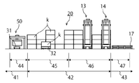
- FIG. 2 is a side view showing II-II in FIG.
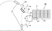
- FIG. 3 is an enlarged plan view showing the sea-side delivery area 44 of FIG.
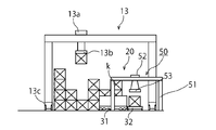
- FIG. 4 is an enlarged view showing IV-IV in FIG.
- FIG. 5 is a front view showing VV in FIG.
- FIG. 6 is a view showing the turning during the delivery of the container.
- FIG. 7 is a view showing the turning during the delivery of the container.
- FIG. 8 is a view showing a container terminal according to the second embodiment of the present invention.
- FIG. 9 is an enlarged view showing IX-IX in FIG.
- FIG. 10 is a front view showing a conventional container terminal.
- the container terminal 10 has a ship 11 that pierces the quay 1, a quay crane 12 in the quay apron area 41, and a storage area 42 that has a longitudinal direction in a direction perpendicular to the traveling direction of the quay crane 12.
- Lane 20 is provided.
- a plurality of storage lanes 20 a first yard crane 13 (hereinafter referred to as the sea side yard crane 13) provided near the sea side that can reciprocate in the longitudinal direction across the storage lanes 20,
- a second yard crane 14 hereinafter referred to as a land side yard crane 14
- the gate yard 43 is provided with a management building 15 and a gate 16 serving as an entrance to the outside.
- the container k is an ISO standard container having a width of 8 feet, a height of 8 feet, a length of 20 feet or 40 feet, but may be a container of other standards.
- the orbiting carriage 31 runs on the quay apron area 42
- the round-trip carriage 32 runs on the storage area 42
- the foreign chassis 33 runs on the gate yard 43.
- a circular path 34 in which the circular transport carriage 31 travels in an annular manner in the quay apron area 41 and a round-trip path 35 in which the reciprocating carriage 32 reciprocates in the longitudinal direction between adjacent areas of the storage lanes 20 are provided.
- a first delivery area 44 (hereinafter referred to as a sea-side delivery area 44) is provided in the quay apron area 41, and a storage area 42 is used to store containers that are mainly carried in from the sea side.
- a carry-out container area 46 for storing containers mainly carried out from the land side
- a second delivery area 47 (hereinafter referred to as a land-side delivery area 47) is provided in the gate yard 43.
- the land-side delivery area 47 includes a safety fence 17 so that the foreign chassis 33 does not enter the storage area 42.
- the carry-in container area 45 is an area where the foreign chassis 33 is loaded from the outside of the container terminal 10 and the container k loaded into the ship 11 is arranged.
- the carry-out container area 46 is unloaded from the ship 11 and the foreign chassis 33 is loaded. This is an area in which a container k to be carried out of the container terminal 10 is arranged.
- the delivery stand 50 is provided in the sea side delivery area 44.
- the sea-side delivery area 44 is an area where the circular transport carriage 31 and the reciprocating carriage 32 deliver the container k via the delivery platform 50
- the land-side delivery area 47 is a land-side yard crane where the round-trip carriage 32 and the foreign chassis 33 are connected.
- 14 is an area in which the container k is transferred via 14.
- the orbiting transport cart 31 transports the container k to the delivery platform 50.
- the delivery stand 50 delivers the container k to the round trip carriage 32.
- the reciprocating carriage 32 that has received the container k travels on the reciprocating path 35 and waits at the designated position where the container k in the unloading container area 46 is placed, or the land-side yard crane 14.
- the round-trip carriage 32 that has delivered the container k to the yard cranes 13 and 14 returns to the delivery platform 50 to transport the container again.
- the loading operation of the container k to the ship 11 is also the reverse of the above operation.
- the container terminal 10 can reduce the movement of the yard cranes 13 and 14 even if the container terminal 10 is arranged in the storage lane 20 with high cargo handling efficiency. This is because the circular transport carriage 31 and the reciprocating carriage 32 deliver the container k through the delivery platform 50 in the sea delivery area 44, so that the sea yard crane 13 does not move to the sea delivery area 44. This is because the yard cranes 13 and 14 do not grab and run the container k. In addition, energy consumed by the container terminal can be suppressed by reducing the movement of the yard cranes 13 and 14.
- a delivery path 36 is provided that allows the orbiting carriage 31 to enter the delivery platform 50.
- the delivery path 36 is a path that branches from the circulation path 34 to the delivery platform 50, and is formed so as to travel in a direction substantially orthogonal to the reciprocation path 35 when the circulation transport carriage 31 passes through the delivery platform 50. Yes.
- the delivery path 36 and the reciprocating path 35 intersect at a substantially right angle when the delivery platform 50 is provided.
- the intersection of the delivery route 36 and the round trip route 35 is an intersection.
- the circular transport carriage 31 and the reciprocating carriage 32 are formed by an automatic guided carriage (hereinafter referred to as AGV). Since the orbiting conveyance cart 31 does not perform switchback running, the switchback running function and the safety sensor for avoiding collision on either the front or rear of the orbiting conveyance cart 31 can be omitted.
- AGV automatic guided carriage
- the cost of the circulating transport cart 31 can be suppressed. Further, in traveling when transporting the container of the circular transport cart 31, it is possible to travel more smoothly when entering the delivery platform 50, and the container transport operation can be performed quickly.
- the reciprocating path 35 is formed by a pair of rails, and is embedded in the ground so that the rails do not protrude from the ground.
- the traveling device 32b of the reciprocating carriage 32 is formed with wheels having flanges that can travel on rails. According to this configuration, since the reciprocating carriage 32 reciprocates along the rail, it is possible to omit a device for detecting the electromagnetic tape laid on the ground, and it is not necessary to bend only by reciprocating on the rail.
- the reciprocating carriage 32 can be manufactured with a carriage that is cheaper than AGV.
- the traveling route of the circular transport carriage 31 and the traveling route of the reciprocating carriage 32 intersect, one of them is formed in a rail shape and embedded in the ground, so that the other traveling route is not disturbed.
- the delivery path 36 and the reciprocating path 35 are formed of electromagnetic tape
- the circular transport carriage 31 and the reciprocating carriage 32 are formed of AGV, one of the traveling paths is formed in a rail shape, so that the traveling paths do not cross each other. . For this reason, safety can be sufficiently maintained even if the traveling routes are crossed.
- the delivery platform 50 is provided in the sea-side delivery area 44 so as to straddle the intersection where the delivery route 36 on which the circular conveyance carriage 31 travels and the reciprocation route 35 on which the round-trip carriage 32 travels.
- the leg part 51, the upper apparatus 52, and the hanging tool 53 are provided.
- the leg portion 51 is formed so that the circular transport carriage 31 and the reciprocating carriage 32 can enter between the leg portions 51 so that the container k does not collide with the leg portions 51 even if the container k is swung between the leg portions 51.
- the leg part 51 does not need to travel, it is not necessary to provide a traveling device.
- the upper device 52 can wind up and down the hanger 53.
- the spreader 53 is suitable for lifting and lowering the container k, it can be replaced with a hook block, a grab bucket, or a lifting magnet.
- the delivery platform 50 is not limited to the above-described configuration, and it is sufficient that the container k can be delivered to the circular transport carriage 31 and the reciprocating carriage 32, and a top lifter, a reach stacker, or the like can be used.
- the upper device 52 is provided with a turning mechanism (not shown) for turning the lifting tool 53 about the central axis in the vertical direction.
- This turning mechanism includes, for example, a mechanism that rotates a plurality of wires that support the suspension 53 with a motor or the like, a mechanism that adjusts the lifting and lowering of the plurality of wires that support the suspension 53 and the suspension 53, and the like. Can be used. Or you may form the upper apparatus 52 by a turning trolley.
- the orbiting carriage 31 enters the delivery platform 50.
- the traveling direction of the circular transport carriage 31 is substantially perpendicular to the traveling direction of the reciprocating carriage 32, and the longitudinal direction of the container k is also the same direction.
- the delivery platform 50 lowers the suspension member 53 and grips the container k.
- FIG. 6C after the container k is wound up, the container k is turned (see arrow). Then, as shown in FIG. 6 (d), the longitudinal direction of the container k is directed to the traveling direction of the reciprocating carriage 32.
- the circulating transport cart 31 that has delivered the container k travels as it is, and returns from the delivery route 36 to the circulating route 34.
- the carriage 32 is stopped so as to be positioned directly under the container k. Then, as shown in FIG. 7 (f), the hanger 53 of the delivery stand 50 is lowered, and the container k is delivered to the reciprocating carriage 32.
- the round-trip cart 32 that has received the container k travels as it is and carries the container k to the storage lane 20.
- some containers k have a length of 40 feet in the longitudinal direction, and when the container k is transported, the longitudinal direction thereof is set to the same direction as the traveling direction of the circular transport carriage 31 and the reciprocating carriage 32. It is preferable. Therefore, the suspension tool 53 of the delivery platform 50 is swung, the container k is swung, and the longitudinal direction of the container k is changed.
- the container terminal 10 As shown in FIG. 8 and FIG. 9, the first round trip path 35a on which the first round trip carriage 32a runs and the second round trip carriage 32b run between the adjacent first storage lane 20a and second storage lane 20b. And a second reciprocating path 35b. Similarly, each of the other storage lanes 20 is provided with two reciprocating carriages 32 and two reciprocating paths 35 between adjacent storage lanes 20.
- a delivery stand 60 is provided in the container terminal 10 so as to straddle the intersection of the round transfer carriage 31, the first round trip carriage 32a, and the second round trip carriage 32b.
- the delivery stand 60 includes a leg portion 61, a trolley (upper device) 62, and a lifting tool 63.
- the leg portion 61 is formed so as to straddle the two reciprocating carriages 32a and 32b and the reciprocating paths 35a and 35b, and so as not to hit the leg portion 61 when the container k is turned.
- the trolley 62 is accompanied by the above-described turning mechanism and the suspension 63, and traverses on the leg portion 61 in a direction substantially orthogonal to the traveling direction of the reciprocating carriages 32a and 32b.
- the same cargo handling operation as described above can be performed. Therefore, the number of delivery platforms 60 provided in the container terminal 10 can be reduced and energy consumption can be further suppressed.
- the delivery platforms 50 and 60 are not limited to the above-described configuration, and may be configured to move the upper devices 51 and 61 in the traveling direction of the reciprocating cart, in the embodiment, the sea-land direction. By doing so, it is not necessary to provide an intersection between the circular transport carriage 31 and the reciprocating carriage 32.
- the terminal container of the present invention reduces the movement of the yard crane as much as possible when handling the container, and instead transports the container with a reciprocating carriage, so it can increase the handling efficiency and reduce energy consumption.
- the cost for the transport cart can be reduced. Therefore, it can be installed on a quay or the like and used as a base for marine transportation and land transportation.
Landscapes
- Warehouses Or Storage Devices (AREA)
Abstract
ヤードクレーンの移動を極力減らし、荷役効率を上げるコンテナターミナルとその制御方法を提供する。蔵置レーン20の一方の端部の外側に第1受渡領域44を設け、第1受渡領域44で周回搬送台車31の走行経路と往復台車32の走行経路が交差する交差点を跨ぐように、周回搬送台車31と往復台車32とにコンテナkの受け渡しを行う受渡架台50を設け、受渡架台50がコンテナkを巻上げ下げする吊り具53と前記吊り具53を旋回させる旋回装置を備え、前記往復台車32が、蔵置レーン20に設けたヤードクレーン13、14と前記受渡架台50との間で、蔵置レーン20に隣接する領域を往復してコンテナkを運搬するように構成された。
Description
本発明は、コンテナターミナルにおいて、蔵置レーンを跨ぐヤードクレーンの移動距離を短くして荷役効率を高めると共に、エネルギーの消費を抑えたコンテナターミナルと制御方法に関する。
コンテナターミナルは船舶に対してコンテナを積み込み又は積み卸し、陸上輸送用の外来シャーシでコンテナを搬入および搬出する施設である。また、積み卸し又は搬入されたコンテナを一時的に保管する施設でもある。
現在、国際航路におけるコンテナ輸送システムの急速な進展に伴い、コンテナターミナル内での荷役や蔵置作業の自動化や省力化が望まれている。すなわち船舶とコンテナターミナル間のコンテナの搬送およびコンテナターミナルでのコンテナの蔵置部分での自動化や高能率化、ならびに低コスト化などが重要になっている。
そこで、蔵置レーンを岸壁に対して略直交する向きに延在させ、蔵置レーン間をスイッチバック走行する無人搬送台車を備え、岸壁側と反対側にゲートを設けて外来シャーシとトランスファークレーン(ヤードクレーン)とが荷役を行う領域を設けたコンテナターミナルがある(例えば特許文献1参照)。このコンテナターミナルは、外来シャーシが蔵置領域に有人の外来シャーシが進入することがないため、蔵置面積率が上昇すると共に、コンテナターミナルをさらに自動化することができたとしている。
しかし、特に蔵置レーンに保管されたコンテナを外来シャーシへの搬出および外来シャーシから搬入して蔵置レーンに保管する際に、ヤードクレーンがコンテナを掴みながら蔵置レーン上を移動するため、荷役効率が悪くなるという問題がある。これはヤードクレーンの移動速度が最速のクレーンでも約18km/hと遅いためである。
また、岸壁に対して略直交する方向、つまり海陸方向に延在する蔵置レーンを設ける場合、外来シャーシから搬入され、船舶へ積み込まれるコンテナを蔵置レーンの海側に配置し、船舶から積み卸しされて外来シャーシへ搬出されるコンテナを蔵置レーンの陸側に配置すると荷役効率は上がる。しかし、特許文献1に記載のコンテナターミナルでは、蔵置レーンに荷役効率の高い配置でコンテナを蔵置するとヤードクレーンの移動距離を多くしなければならない。特に外来シャーシへの搬出および搬入の際に、ヤードクレーンがコンテナを掴み上げ、蔵置レーンを走行するため、効率が落ちる。
さらに、ヤードクレーンがコンテナを吊って運搬する方法は荷役効率が悪く、そのため、無駄なエネルギーを消費しているという問題が発生する。
一方で、蔵置レーンの長手方向に移動するヤードクレーンを備え、搬出されるコンテナと搬入されたコンテナを区分して蔵置するコンテナターミナルにおいて、図10に示すように、蔵置レーン110を跨ぐヤードクレーン111と、そのヤードクレーン111を跨ぐ大きなヤードクレーン112を設けたコンテナターミナルがある。このコンテナターミナルはヤードクレーン111とヤードクレーン112とが衝突せずにすれ違うことができるため、蔵置レーン110で効率的にコンテナkを配置することができる。しかし、やはりヤードクレーン111および112を長距離移動させなければならないため、その分時間が掛かってしまう。加えて大型のヤードクレーン112の製造コストや維持コストが高くなるという問題も発生する。
そこで本発明の目的は、ヤードクレーンの移動距離(走行距離)を減少し、荷役効率を上げると共にエネルギーの消費を抑えることができるコンテナターミナルとその制御方法を提供することである。また、周回搬送台車をスイッチバック走行させることなく、周回搬送台車の走行をより円滑にすることができるコンテナターミナルとその制御方法を提供することである。
上記の問題を解決するための本発明のコンテナターミナルは、岸壁クレーンと、コンテナを所定の位置に配置する蔵置レーンとを備え、周回搬送台車がコンテナを運搬するコンテナターミナルにおいて、前記蔵置レーンの隣接する領域を長手方向に往復し、コンテナを運搬する少なくとも1台の往復台車と、蔵置レーンの端部の外側に、前記周回搬送台車と前記往復台車とがコンテナを受け渡す第1受渡領域とを設け、前記第1受渡領域で前記周回搬送台車の走行経路と前記往復台車の走行経路とが交差する交差点を跨ぐように、コンテナを上げ下げする吊り具と前記吊り具を旋回させる旋回機構を備えた受渡架台を設けて構成される。
この構成によれば、蔵置レーンの端部の外側の、周回搬送台車と往復台車との走行経路の交差点で、受渡架台がコンテナの受け渡しを行う。そして、往復台車が受渡架台と蔵置レーンに設けられたヤードクレーンとの間を往復してコンテナを運搬することができる。そのため、ヤードクレーンが走行してコンテナを運搬することがなくなり、ヤードクレーンの移動距離(走行距離)を低減することができ、コンテナターミナルの荷役効率を上げることができる。また、ヤードクレーンよりも、エネルギー消費の少ない受渡架台で、周回搬送台車と往復台車のコンテナの受け渡しを行うため、よりエネルギーの消費を抑えることができる。
また、周回搬送台車は、蔵置レーンの端部の外側に設けた受渡架台にコンテナを受け渡しする際に、スイッチバック走行せずに行うことができる。そのため、周回搬送台車からスイッチバック走行機能と周回搬送台車の前後のどちらか一方の安全確認センサー機能を除くことができ、周回搬送台車にかかるコストを抑えることができる。また、上記の構成から、周回搬送台車と往復台車の走行方向は略直交する。そのため、コンテナを周回搬送台車と往復台車とに受け渡す際にコンテナを旋回させる必要があるので、受渡架台は吊り具を、鉛直方向を中心軸として旋回させる旋回機構を備える。よって、コンテナの長手方向をそれぞれの走行方向と一致させることができので、コンテナの運搬に支障をきたすことがなくなる。
また、上記のコンテナターミナルは、隣接する前記蔵置レーンと前記往復台車を、第1蔵置レーンと第1往復台車と第2往復台車と第2蔵置レーンの順番に配置し、前記周回搬送台車の経路と第1往復台車の経路との交差点と、前記周回搬送台車の経路と第2往復台車の経路との交差点を跨ぐように、1台の前記受渡架台を設け、前記受渡架台が、前記周回搬送台車と前記第1往復台車又は前記第2往復台車に対してコンテナの受け渡しを行うように、前記吊り具を前記往復台車の走行方向と略直交する方向に横行させる移動装置を備えて構成される。
この構成によれば、隣接する2列の蔵置レーンの間に、2台の往復台車を配置する。そして、2台の往復台車を跨ぐように受渡架台を形成し、また、2台の往復台車の間で吊り具を移動させることができる。そのため、隣接する2列の蔵置レーンで1台の受渡架台を共有することができ、受渡架台の台数を減らすことができる。
加えて、上記のコンテナターミナルは、前記周回搬送台車と前記往復台車を無人搬送台車で形成し、前記周回経路又は前記往復経路のどちらか一方をレール状に形成すると共に、地面に埋設して構成される。
例えば、無人搬送台車は地面上に敷設された電磁テープを検知することで走行しているが、その走行経路が交差してしまうと制御が難しく、また、その交差点での滞留や衝突などの問題も発生する。しかし、この構成によれば、周回搬送台車と往復台車を無人搬送台車(以下AGVという)で形成し、どちらか一方の走行経路である周回経路又は往復経路をレール状に形成して地面に埋設する。もう一方の走行経路である電磁テープなどは地面に敷設する。すると、走行経路が交差しても、周回搬送台車と往復台車の制御が混線することがないので、円滑に周回搬送台車と往復台車を走行させることができる。
上記の目的を達成するための本発明のコンテナターミナルの制御方法は、岸壁クレーンと、コンテナを所定の位置に配置する蔵置レーンと、該蔵置レーンを跨ぐ少なくとも1台のヤードクレーンとを備え、周回搬送台車がコンテナを運搬するコンテナターミナルの制御方法において、前記蔵置レーンの端部の外側で、受渡架台が吊り具の巻上げ下げと吊り具の旋回によって、前記周回搬送台車と往復台車とのコンテナの受け渡しを行う工程と、前記蔵置レーンの隣接する領域を長手方向に前記往復台車が往復して前記受渡架台と前記ヤードクレーンとにコンテナを運搬する工程を有する。
この方法によれば、往復台車によって、蔵置レーンのコンテナの運搬を行うため、ヤードクレーンがコンテナを掴み走行することがなく、ヤードクレーンの移動距離を減らすことができるので、荷役効率を上げることができる。また、周回搬送台車の走行を円滑にするため、受渡架台の下で周回搬送台車と往復台車との走行経路が交差しても、受渡架台がコンテナを旋回することができるため、周回搬送台車と往復台車とのコンテナの受け渡しを円滑に行うことができる。
本発明によれば、ヤードクレーンの移動距離(走行距離)を低減し、荷役効率を上げると共にエネルギーの消費を抑えることができる。また、周回搬送台車がコンテナを受け渡す際にスイッチバック走行を必要とせず、また、その前後のどちらか一方の衝突回避用の安全センサーも必要としないため、周回搬送台車に掛かるコストを下げることができる。加えて、AGVである周回搬送台車と往復台車との交差点でのそれぞれの走行を円滑にすることができる。
以下、本発明に係る実施の形態のコンテナターミナルとコンテナターミナルの制御方法について、図面を参照しながら説明する。
図1に示すように、コンテナターミナル10は岸壁1に接岸する船舶11と、岸壁エプロン領域41に岸壁クレーン12と、蔵置領域42に岸壁クレーン12の走行方向に直交する方向に長手方向を持つ蔵置レーン20とを備える。また、蔵置領域42に、複数の蔵置レーン20と、各蔵置レーン20を跨ぎ、その長手方向に往復可能な海側寄りに設けた第1ヤードクレーン13(以下海側ヤードクレーン13という)と、陸側寄りに設けた第2ヤードクレーン14(以下陸側ヤードクレーン14という)とを備える。さらに、ゲートヤード43に、管理棟15や、外部への出入り口になるゲート16を設ける。
ここでは1例として岸壁クレーン12の走行方向に直交する方向に長手方向を持つ蔵置レーンを6レーンとしたが、コンテナターミナル10によっては、岸壁クレーン12の走行方向に長手方向を持つ蔵置レーンや、また様々なレーン数にすることができる。さらに、岸壁クレーン12も1隻の船舶11に対して何台設置してもよく、船舶11も1隻とは限らない。コンテナkは幅8フィート、高さ8フィート、長さ20フィートまたは40フィートのISO規格コンテナであるが、それ以外の規格のコンテナでもよい。
また、コンテナターミナル10には、周回搬送台車31が岸壁エプロン領域42を走行し、往復台車32が蔵置領域42を走行し、外来シャーシ33がゲートヤード43を走行している。周回搬送台車31が岸壁エプロン領域41内を環状に走行する周回経路34と、往復台車32が各蔵置レーン20の隣接する領域を長手方向に往復する往復経路35とを設ける。
図2に示すように、岸壁エプロン領域41に第1受渡領域44(以下海側受渡領域44という)を設け、蔵置領域42を海側よりの主に搬入されたコンテナを蔵置する搬入コンテナ領域45と、陸側よりの主に搬出されるコンテナを蔵置する搬出コンテナ領域46とを設け、ゲートヤード43に第2受渡領域47(以下陸側受渡領域47という)を設ける。また、陸側受渡領域47には、外来シャーシ33が蔵置領域42へ侵入しないように安全柵17を備える。
搬入コンテナ領域45は、コンテナターミナル10の外部から外来シャーシ33が搬入し、船舶11へ積み込まれるコンテナkを配置する領域であり、搬出コンテナ領域46は、船舶11から積み卸しされ、外来シャーシ33がコンテナターミナル10の外部へ搬出するコンテナkを配置する領域である。このように蔵置レーン20に配置されるコンテナkを分類することで、効率の高い荷役を行うことが可能となる。
そして、海側受渡領域44に受渡架台50を設ける。海側受渡領域44は周回搬送台車31と往復台車32とが受渡架台50を介してコンテナkを受け渡す領域であり、陸側受渡領域47は往復台車32と外来シャーシ33とが陸側ヤードクレーン14を介してコンテナkを受け渡す領域である。
次に本発明の第1の実施の形態のコンテナターミナル10で行われるコンテナkの荷役動作を説明する。船舶11からコンテナkを蔵置レーン20の搬出コンテナ領域46に積み卸しするときは、周回搬送台車31が受渡架台50まで、コンテナkを運搬する。すると、受渡架台50がコンテナkを往復台車32へ渡す。そして、コンテナkを受け取った往復台車32は往復経路35上を走行し、搬出コンテナ領域46内のコンテナkを配置する指定の位置で待機している海側ヤードクレーン13又は、陸側ヤードクレーン14まで走行し、ヤードクレーン13、14にコンテナkを渡す。そして、ヤードクレーン13、14にコンテナkを受け渡した往復台車32は再度コンテナを運搬するために受渡架台50へ戻る。以上で船舶11からコンテナkを積み卸しする動作が完了する。この動作を船舶11の指定されたコンテナk全てに対して行う。船舶11へのコンテナkの積み込み動作も上記の動作と逆の動作を行う。
上記の動作により、コンテナターミナル10は蔵置レーン20に荷役効率の高い配置を行っても、ヤードクレーン13、14の移動を減少させることができる。これは海側受渡領域44で周回搬送台車31と往復台車32とが受渡架台50を介してコンテナkの受け渡しを行うため、海側ヤードクレーン13を海側受渡領域44へ移動することがないことと、ヤードクレーン13、14がコンテナkを掴み走行することがないからである。加えて、ヤードクレーン13、14の移動を低減することで、コンテナターミナルの消費するエネルギーを抑えることができる。
図3に示すように、周回搬送台車31が受渡架台50への進入を可能にする受渡経路36を設ける。受渡経路36は、周回経路34から受渡架台50へと分岐する経路であり、周回搬送台車31が受渡架台50を通過するときは、往復経路35と略直交する方向を走行するように形成されている。受渡経路36と往復経路35とは受渡架台50を設けたところで略直角に交差している。この受渡経路36と往復経路35が交差した箇所が交差点となる。
周回搬送台車31と往復台車32とは無人搬送台車(以下、AGVという)で形成する。周回搬送台車31はスイッチバック走行をしないため、スイッチバック走行機能と、周回搬送台車31の前後のどちらか一方の衝突回避用の安全センサーを省くことができる。
上記の構成から、周回搬送台車31のコストを抑えることができる。また、周回搬送台車31のコンテナを運搬する際の走行において、受渡架台50へ侵入する際により円滑に走行することが可能となり、コンテナの運搬作業を迅速に行うことができる。
図4に示すように、往復経路35を1組のレールで形成し、地面からレールがはみ出ないように、地面に埋設する。そして、往復台車32の走行装置32bを、レール上を走行可能なフランジを有した車輪で形成する。この構成によれば、往復台車32はレール上に沿って往復するので、地面に敷設した電磁テープを検知する装置を省くことができることや、レール上を往復するだけで曲がる必要がないことから、往復台車32をAGVよりも安価な台車で製造することが可能になる。
また、周回搬送台車31の走行経路と往復台車32の走行経路を交差しても、一方がレール状に形成され、地面に埋設されているため、もう一方の走行経路を邪魔することがない。例えば受渡経路36と往復経路35を電磁テープで形成すると交差点では、電磁テープの検知に問題が生じ、AGVが円滑に走行しない問題が発生する。しかし、上記の構成であれば、周回搬送台車31と往復台車32とをAGVで形成しても、片方の走行経路がレール状に形成されているため、互いの走行経路が混線することがない。そのため、走行経路を交差させても、十分に安全を保つことができる。
図5に示すように、受渡架台50は周回搬送台車31が走行する受渡経路36と往復台車32が走行する往復経路35との交差する交差点を跨ぐように、海側受渡領域44に設けられ、脚部51と上部装置52と吊り具53を備える。脚部51を、周回搬送台車31と往復台車32が脚部51の間に侵入でき、コンテナkを脚部51の間で旋回しても脚部51に衝突しないように形成する。また、脚部51は走行する必要はないため、走行装置は備える必要がない。
上部装置52は吊り具53を巻上げ下げすることができる。吊り具53は、コンテナkを巻上げ下げする場合はスプレッダが適しているが、フックブロックやグラブバケット、又はリフチングマグネットなどに換えることができる。また、受渡架台50は上記の構成に限らず、周回搬送台車31と往復台車32とへコンテナkの受け渡しが行うことができればよく、トップリフターやリーチスタッカーなどを使用することもできる。
加えて、上部装置52は吊り具53を鉛直方向に中心軸として旋回させる旋回機構(図示せず)を備えている。この旋回機構は、例えば吊り具53を支えている複数のワイヤーをモータなどで回転させる機構や、吊り具53と吊り具53を支えている複数のワイヤーの上げ下げを調整して旋回させる機構などを用いることができる。若しくは上部装置52を旋回トロリで形成してもよい。
次にこの受渡架台50の吊り具53を旋回させたコンテナkの受け渡し動作を説明する。図6(a)に示すように、周回搬送台車31が受渡架台50に、侵入する。このとき周回搬送台車31の走行方向は往復台車32の走行方向と略直角な方向になり、コンテナkの長手方向も同方向となる。図6(b)に示すように、周回搬送台車31が停止した後、受渡架台50は吊り具53を巻下げ、コンテナkを掴む。次に図6(c)に示すように、コンテナkを巻上げた後、コンテナkを旋回させる(矢印参照)。すると、図6(d)に示すように、コンテナkの長手方向が往復台車32の走行方向に向く。コンテナkを受け渡した周回搬送台車31はそのまま走行し、受渡経路36から周回経路34へと戻る。
次に、図7(e)に示すように、往復台車32がコンテナkの真下に位置するように停止する。そして、図7(f)に示すように、受渡架台50の吊り具53が巻下がり、コンテナkを往復台車32へ渡す。コンテナkを受け取った往復台車32はそのまま走行し、コンテナkを蔵置レーン20へと運ぶ。
上記の動作により、前述と同様の効果を得ることができる。また、コンテナkは前述したように長手方向の長さが40フィートあるものもあり、コンテナkを運搬する際にはその長手方向を周回搬送台車31及び往復台車32の走行方向と同一方向にすることが好ましい。そこで、受渡架台50の吊り具53を旋回させ、コンテナkを旋回させて、コンテナkの長手方向を変える。上記の動作により、周回搬送台車31の走行を円滑にするために、受渡架台50を通過する際に、往復台車32の走行方向と略直交する方向に走行させても、受渡架台50の吊り具53が旋回し、コンテナkの長手方向を周回搬送台車31及び往復台車32の走行方向に合わせることができるので、荷役効率を上げることができる。
さらに、周回搬送台車31はスイッチバック走行をする必要がなくなるため、走行が円滑になり、コンテナの運搬効率を上げることができる。そのため、周回搬送台車31の台数を減らすことができる。
次に、本発明に係る第2の実施の形態のコンテナターミナル10について説明する。図8、図9に示すように、隣接する第1蔵置レーン20aと第2蔵置レーン20bとの間に、第1往復台車32aが走行する第1往復路35aと、第2往復台車32bが走行する第2往復路35bとを設ける。その他の各蔵置レーン20も同様に、隣接する蔵置レーン20の間に2台の往復台車32と2本の往復路35を設ける。
また、コンテナターミナル10に受渡架台60を、周回搬送台車31と、第1往復台車32aと第2往復台車32bの両方の交差点を跨ぐように設ける。受渡架台60は脚部61とトロリ(上部装置)62と吊り具63とを備える。脚部61は、2台の往復台車32a、32bと往復路35a、35bとを跨ぐように、また、コンテナkを旋回させたときに脚部61にぶつからないように形成されている。トロリ62は前述した旋回機構と、吊り具63を伴い、脚部61上を往復台車32a、32bの走行方向に略直交する方向に横行する。
上記の構成によれば、2列の蔵置レーン20a、20bに対して、1台の受渡架台60を設ければ前述と同様の荷役動作を行うことができる。そのため、コンテナターミナル10に設ける受渡架台60の台数を減らすことができ、よりエネルギーの消費を抑えることができる。
受渡架台50、及び60は、前述の構成に限らず、往復台車の走行方向、実施の例では海陸方向に上部装置51、及び61を移動させる構成にしてもよい。そうすることで、周回搬送台車31と往復台車32との交差点を設ける必要がなくなる。
本発明のターミナルコンテナは、コンテナを荷役する際に、ヤードクレーンの移動を極力減らし、代わりに往復台車でコンテナの運搬をするので、荷役効率を上げると共にエネルギーの消費を抑えることができ、さらに周回搬送台車に掛かるコストを抑えることができる。そのため、岸壁などに設け、海上輸送と陸上輸送との拠点として用いることができる。
1 岸壁
10 コンテナターミナル
11 船舶
12 岸壁クレーン
13 海側ヤードクレーン
14 陸側ヤードクレーン
15 管理棟
16 ゲート
17 安全柵
20 蔵置レーン
31 周回搬送台車
32 往復台車
33 外来シャーシ
34 周回経路
35 往復経路
41 岸壁エプロン領域
42 蔵置領域
43 ゲートヤード
44 海側受渡領域(第1受渡領域)
45 搬入コンテナ領域
46 搬出コンテナ領域
47 陸側受渡領域(第2受渡領域)
50、60 受渡架台
10 コンテナターミナル
11 船舶
12 岸壁クレーン
13 海側ヤードクレーン
14 陸側ヤードクレーン
15 管理棟
16 ゲート
17 安全柵
20 蔵置レーン
31 周回搬送台車
32 往復台車
33 外来シャーシ
34 周回経路
35 往復経路
41 岸壁エプロン領域
42 蔵置領域
43 ゲートヤード
44 海側受渡領域(第1受渡領域)
45 搬入コンテナ領域
46 搬出コンテナ領域
47 陸側受渡領域(第2受渡領域)
50、60 受渡架台
Claims (4)
- 岸壁クレーンと、コンテナを所定の位置に配置する蔵置レーンとを備え、周回搬送台車がコンテナを運搬するコンテナターミナルにおいて、
前記蔵置レーンの隣接する領域を長手方向に往復し、コンテナを運搬する少なくとも1台の往復台車と、蔵置レーンの端部の外側に、前記周回搬送台車と前記往復台車とがコンテナを受け渡す第1受渡領域とを設け、
前記第1受渡領域で前記周回搬送台車の走行経路と前記往復台車の走行経路とが交差する交差点を跨ぐように、コンテナを上げ下げする吊り具と前記吊り具を旋回させる旋回機構を備えた受渡架台を設けことを特徴とするコンテナターミナル。 - 隣接する前記蔵置レーンと前記往復台車を、第1蔵置レーンと第1往復台車と第2往復台車と第2蔵置レーンの順番に配置し、前記周回搬送台車の経路と第1往復台車の経路との交差点と、前記周回搬送台車の経路と第2往復台車の経路との交差点を跨ぐように、1台の前記受渡架台を設け、
前記受渡架台が、前記周回搬送台車と前記第1往復台車又は前記第2往復台車に対してコンテナの受け渡しを行うように、前記吊り具を前記往復台車の走行方向と略直交する方向に横行させる移動装置を備えたことを特徴とする請求項1に記載のコンテナターミナル。 - 前記周回搬送台車と前記往復台車とを無人搬送台車で形成し、前記周回経路又は前記往復経路のどちらか一方をレール状に形成すると共に、地面に埋設したことを特徴とする請求項1又は2に記載のコンテナターミナル。
- 岸壁クレーンと、コンテナを所定の位置に配置する蔵置レーンと、該蔵置レーンを跨ぐ少なくとも1台のヤードクレーンとを備え、周回搬送台車がコンテナを運搬するコンテナターミナルの制御方法において、
前記蔵置レーンの端部の外側で、受渡架台が吊り具の巻上げ下げと吊り具の旋回によって、前記周回搬送台車と往復台車とのコンテナの受け渡しを行う工程と、前記蔵置レーンの隣接する領域を長手方向に前記往復台車が往復して前記受渡架台と前記ヤードクレーンとにコンテナを運搬する工程を有することを特徴とするコンテナターミナルの制御方法。
Applications Claiming Priority (2)
| Application Number | Priority Date | Filing Date | Title |
|---|---|---|---|
| JP2011074523A JP5698051B2 (ja) | 2011-03-30 | 2011-03-30 | コンテナターミナルとその制御方法 |
| JP2011-074523 | 2011-03-30 |
Publications (1)
| Publication Number | Publication Date |
|---|---|
| WO2012133280A1 true WO2012133280A1 (ja) | 2012-10-04 |
Family
ID=46930998
Family Applications (1)
| Application Number | Title | Priority Date | Filing Date |
|---|---|---|---|
| PCT/JP2012/057711 Ceased WO2012133280A1 (ja) | 2011-03-30 | 2012-03-26 | コンテナターミナルとその制御方法 |
Country Status (2)
| Country | Link |
|---|---|
| JP (1) | JP5698051B2 (ja) |
| WO (1) | WO2012133280A1 (ja) |
Cited By (6)
| Publication number | Priority date | Publication date | Assignee | Title |
|---|---|---|---|---|
| CN108466844A (zh) * | 2018-05-16 | 2018-08-31 | 青岛港国际股份有限公司 | 一种自动化集装箱码头 |
| CN110239967A (zh) * | 2019-07-01 | 2019-09-17 | 机科(山东)重工科技股份有限公司 | 一种自动化集装箱堆场 |
| CN113153381A (zh) * | 2021-02-02 | 2021-07-23 | 中船第九设计研究院工程有限公司 | 一种液压台车运移系统 |
| CN113602825A (zh) * | 2021-10-08 | 2021-11-05 | 天津港第二集装箱码头有限公司 | 顺岸式全自动化集装箱码头装卸系统及其装卸工艺 |
| CN115947131A (zh) * | 2022-11-23 | 2023-04-11 | 青岛港国际股份有限公司 | 一种集装箱码头 |
| CN120196059A (zh) * | 2025-03-07 | 2025-06-24 | 哈尔滨商业大学 | 一种直线往复多rgv协同作业的出入库调度方法 |
Families Citing this family (3)
| Publication number | Priority date | Publication date | Assignee | Title |
|---|---|---|---|---|
| JP6113551B2 (ja) * | 2013-03-29 | 2017-04-12 | 三井造船株式会社 | コンテナターミナル及びコンテナターミナルの運用方法 |
| JP6155217B2 (ja) * | 2014-03-31 | 2017-06-28 | 三井造船株式会社 | コンテナターミナル及びコンテナターミナルの運用方法 |
| CN106530755A (zh) * | 2016-12-19 | 2017-03-22 | 盐田国际集装箱码头有限公司 | 一种龙转箱街车排队调箱通过方法 |
Citations (3)
| Publication number | Priority date | Publication date | Assignee | Title |
|---|---|---|---|---|
| JPH11292291A (ja) * | 1998-04-14 | 1999-10-26 | Ishikawajima Harima Heavy Ind Co Ltd | コンテナターミナル |
| JP2005075537A (ja) * | 2003-08-29 | 2005-03-24 | Mitsubishi Heavy Ind Ltd | コンテナターミナル |
| JP2010265117A (ja) * | 2009-04-15 | 2010-11-25 | Jfe Engineering Corp | 移載システム及び該移載システムを備える物品荷役施設並びに、コンテナ移載装置及び該コンテナ移載装置を備えるコンテナターミナル |
Family Cites Families (3)
| Publication number | Priority date | Publication date | Assignee | Title |
|---|---|---|---|---|
| JPS60195266U (ja) * | 1984-06-07 | 1985-12-26 | 三菱重工業株式会社 | 運搬装置 |
| JP2007223782A (ja) * | 2006-02-27 | 2007-09-06 | Mitsubishi Heavy Ind Ltd | コンテナターミナル |
| JP2009242084A (ja) * | 2008-03-31 | 2009-10-22 | Mitsui Eng & Shipbuild Co Ltd | レールマウント式門型クレーンの片ターンテーブルによるブロック移動方法及び装置 |
-
2011
- 2011-03-30 JP JP2011074523A patent/JP5698051B2/ja active Active
-
2012
- 2012-03-26 WO PCT/JP2012/057711 patent/WO2012133280A1/ja not_active Ceased
Patent Citations (3)
| Publication number | Priority date | Publication date | Assignee | Title |
|---|---|---|---|---|
| JPH11292291A (ja) * | 1998-04-14 | 1999-10-26 | Ishikawajima Harima Heavy Ind Co Ltd | コンテナターミナル |
| JP2005075537A (ja) * | 2003-08-29 | 2005-03-24 | Mitsubishi Heavy Ind Ltd | コンテナターミナル |
| JP2010265117A (ja) * | 2009-04-15 | 2010-11-25 | Jfe Engineering Corp | 移載システム及び該移載システムを備える物品荷役施設並びに、コンテナ移載装置及び該コンテナ移載装置を備えるコンテナターミナル |
Cited By (8)
| Publication number | Priority date | Publication date | Assignee | Title |
|---|---|---|---|---|
| CN108466844A (zh) * | 2018-05-16 | 2018-08-31 | 青岛港国际股份有限公司 | 一种自动化集装箱码头 |
| CN108466844B (zh) * | 2018-05-16 | 2024-01-09 | 青岛港国际股份有限公司 | 一种自动化集装箱码头 |
| CN110239967A (zh) * | 2019-07-01 | 2019-09-17 | 机科(山东)重工科技股份有限公司 | 一种自动化集装箱堆场 |
| CN110239967B (zh) * | 2019-07-01 | 2023-08-18 | 上海海丰智能科技有限公司 | 一种自动化集装箱堆场 |
| CN113153381A (zh) * | 2021-02-02 | 2021-07-23 | 中船第九设计研究院工程有限公司 | 一种液压台车运移系统 |
| CN113602825A (zh) * | 2021-10-08 | 2021-11-05 | 天津港第二集装箱码头有限公司 | 顺岸式全自动化集装箱码头装卸系统及其装卸工艺 |
| CN115947131A (zh) * | 2022-11-23 | 2023-04-11 | 青岛港国际股份有限公司 | 一种集装箱码头 |
| CN120196059A (zh) * | 2025-03-07 | 2025-06-24 | 哈尔滨商业大学 | 一种直线往复多rgv协同作业的出入库调度方法 |
Also Published As
| Publication number | Publication date |
|---|---|
| JP5698051B2 (ja) | 2015-04-08 |
| JP2012206838A (ja) | 2012-10-25 |
Similar Documents
| Publication | Publication Date | Title |
|---|---|---|
| JP5676338B2 (ja) | コンテナターミナルとその制御方法 | |
| JP5698051B2 (ja) | コンテナターミナルとその制御方法 | |
| JP5793323B2 (ja) | コンテナターミナルとその制御方法 | |
| JP5755404B2 (ja) | コンテナターミナル | |
| AU2015391350B2 (en) | Method and container transfer installation for placing containers into and removing containers from container storage areas | |
| JP6492324B2 (ja) | コンテナターミナル | |
| JP4690594B2 (ja) | コンテナターミナル | |
| JP2017502896A (ja) | コンテナ用の中間保管領域を備えるスタッキングクレーン | |
| JP4418195B2 (ja) | コンテナターミナル | |
| JP5969095B2 (ja) | コンテナターミナルとその制御方法 | |
| JP6138720B2 (ja) | コンテナターミナル及びコンテナターミナルの運用方法 | |
| JP5953090B2 (ja) | コンテナターミナルとその制御方法 | |
| JP5840853B2 (ja) | 岸壁クレーンを備えたコンテナターミナルとその制御方法 | |
| JP6234867B2 (ja) | コンテナターミナル及びコンテナターミナルの運用方法 | |
| JP6155217B2 (ja) | コンテナターミナル及びコンテナターミナルの運用方法 | |
| US20170327325A1 (en) | Horse And Saddle Transfer Apparatus For Shipping Containers And Method Of Operation | |
| JP6271323B2 (ja) | コンテナターミナル及びコンテナターミナルの運用方法 | |
| JP6113551B2 (ja) | コンテナターミナル及びコンテナターミナルの運用方法 | |
| JP2013212884A (ja) | コンテナターミナルとその制御方法 | |
| JP6380839B2 (ja) | コンテナターミナル及びコンテナターミナルの運用方法 | |
| JP2015193435A (ja) | コンテナターミナル及びコンテナターミナルの運用方法 | |
| JP2013212890A (ja) | コンテナターミナルとその制御方法 | |
| JP2013212883A (ja) | コンテナターミナルとその制御方法 |
Legal Events
| Date | Code | Title | Description |
|---|---|---|---|
| 121 | Ep: the epo has been informed by wipo that ep was designated in this application |
Ref document number: 12765246 Country of ref document: EP Kind code of ref document: A1 |
|
| NENP | Non-entry into the national phase |
Ref country code: DE |
|
| 122 | Ep: pct application non-entry in european phase |
Ref document number: 12765246 Country of ref document: EP Kind code of ref document: A1 |