WO2012133196A1 - 太陽電池封止材シートの製造方法 - Google Patents
太陽電池封止材シートの製造方法 Download PDFInfo
- Publication number
- WO2012133196A1 WO2012133196A1 PCT/JP2012/057531 JP2012057531W WO2012133196A1 WO 2012133196 A1 WO2012133196 A1 WO 2012133196A1 JP 2012057531 W JP2012057531 W JP 2012057531W WO 2012133196 A1 WO2012133196 A1 WO 2012133196A1
- Authority
- WO
- WIPO (PCT)
- Prior art keywords
- sheet
- solar cell
- temperature
- resin composition
- encapsulant
- Prior art date
- Legal status (The legal status is an assumption and is not a legal conclusion. Google has not performed a legal analysis and makes no representation as to the accuracy of the status listed.)
- Ceased
Links
Images


Classifications
-
- H—ELECTRICITY
- H10—SEMICONDUCTOR DEVICES; ELECTRIC SOLID-STATE DEVICES NOT OTHERWISE PROVIDED FOR
- H10F—INORGANIC SEMICONDUCTOR DEVICES SENSITIVE TO INFRARED RADIATION, LIGHT, ELECTROMAGNETIC RADIATION OF SHORTER WAVELENGTH OR CORPUSCULAR RADIATION
- H10F19/00—Integrated devices, or assemblies of multiple devices, comprising at least one photovoltaic cell covered by group H10F10/00, e.g. photovoltaic modules
-
- B—PERFORMING OPERATIONS; TRANSPORTING
- B29—WORKING OF PLASTICS; WORKING OF SUBSTANCES IN A PLASTIC STATE IN GENERAL
- B29C—SHAPING OR JOINING OF PLASTICS; SHAPING OF MATERIAL IN A PLASTIC STATE, NOT OTHERWISE PROVIDED FOR; AFTER-TREATMENT OF THE SHAPED PRODUCTS, e.g. REPAIRING
- B29C59/00—Surface shaping of articles, e.g. embossing; Apparatus therefor
- B29C59/02—Surface shaping of articles, e.g. embossing; Apparatus therefor by mechanical means, e.g. pressing
- B29C59/04—Surface shaping of articles, e.g. embossing; Apparatus therefor by mechanical means, e.g. pressing using rollers or endless belts
-
- H—ELECTRICITY
- H10—SEMICONDUCTOR DEVICES; ELECTRIC SOLID-STATE DEVICES NOT OTHERWISE PROVIDED FOR
- H10F—INORGANIC SEMICONDUCTOR DEVICES SENSITIVE TO INFRARED RADIATION, LIGHT, ELECTROMAGNETIC RADIATION OF SHORTER WAVELENGTH OR CORPUSCULAR RADIATION
- H10F19/00—Integrated devices, or assemblies of multiple devices, comprising at least one photovoltaic cell covered by group H10F10/00, e.g. photovoltaic modules
- H10F19/80—Encapsulations or containers for integrated devices, or assemblies of multiple devices, having photovoltaic cells
- H10F19/804—Materials of encapsulations
-
- B—PERFORMING OPERATIONS; TRANSPORTING
- B29—WORKING OF PLASTICS; WORKING OF SUBSTANCES IN A PLASTIC STATE IN GENERAL
- B29C—SHAPING OR JOINING OF PLASTICS; SHAPING OF MATERIAL IN A PLASTIC STATE, NOT OTHERWISE PROVIDED FOR; AFTER-TREATMENT OF THE SHAPED PRODUCTS, e.g. REPAIRING
- B29C71/00—After-treatment of articles without altering their shape; Apparatus therefor
- B29C71/02—Thermal after-treatment
-
- Y—GENERAL TAGGING OF NEW TECHNOLOGICAL DEVELOPMENTS; GENERAL TAGGING OF CROSS-SECTIONAL TECHNOLOGIES SPANNING OVER SEVERAL SECTIONS OF THE IPC; TECHNICAL SUBJECTS COVERED BY FORMER USPC CROSS-REFERENCE ART COLLECTIONS [XRACs] AND DIGESTS
- Y02—TECHNOLOGIES OR APPLICATIONS FOR MITIGATION OR ADAPTATION AGAINST CLIMATE CHANGE
- Y02E—REDUCTION OF GREENHOUSE GAS [GHG] EMISSIONS, RELATED TO ENERGY GENERATION, TRANSMISSION OR DISTRIBUTION
- Y02E10/00—Energy generation through renewable energy sources
- Y02E10/50—Photovoltaic [PV] energy
Definitions
- the present invention relates to a method for producing a solar cell encapsulant sheet.
- the present invention relates to a method for producing a sheet suitably used for producing a solar cell encapsulant sheet having a small heat shrinkage and having a clear protrusion formed on the surface.
- a solar cell is a solar cell sealing material sheet (hereinafter referred to as a sealing material sheet) between a light-receiving surface protective material typified by a glass substrate and a back surface protective material called a back sheet. The cell is sealed.
- a sealing material sheet a solar cell sealing material sheet between a light-receiving surface protective material typified by a glass substrate and a back surface protective material called a back sheet. The cell is sealed.
- Crystalline silicon solar cells which are mainstream as solar cell modules, are generally manufactured as follows. First, a glass substrate, a sealing material sheet, a solar battery cell (silicon power generation element), a sealing material sheet, and a back sheet are laminated in this order.
- This sealing material sheet is generally composed of an ethylene-vinyl acetate copolymer (hereinafter referred to as EVA). Subsequently, this laminated body is heated under vacuum with a vacuum laminator, and the sealing material sheet is heated and melted to be cured by crosslinking. In this way, a solar cell module in which the constituent members are bonded without bubbles is manufactured.
- EVA ethylene-vinyl acetate copolymer
- the solar cell module since the solar cell module is used for a long time after manufacturing, its reliability is extremely important. Typical defects that occur in a solar cell module that has been used for a long period of time include peeling between the solar cells and the sealing material sheet, poor appearance such as swelling, and a corresponding decrease in the amount of power generation. The reason for these malfunctions is not necessarily clarified, but studies have been made from the raw material side constituting the encapsulant sheet. For example, a method of adjusting the viscosity of EVA constituting the encapsulant sheet (Patent Document 2) and a method of adding a silane coupling agent to improve the adhesive strength between the solar battery cell and the encapsulant sheet (Patent Document) 3) etc. are being studied.
- Patent Document 6 after forming an embossed shape on the surface of a sheet in the manufacturing process (hereinafter referred to as a process sheet), the process sheet is annealed. Therefore, when the process sheet is sufficiently heated to reduce the heat shrinkage of the encapsulant sheet, the embossed shape formed on the surface of the process sheet is broken by the heating. Conversely, if the heating of the process sheet is loosened in order to maintain the embossed shape, the annealing process becomes insufficient. As described above, in the manufacturing method of Patent Document 6, it is very difficult to achieve both reduction in heat shrinkage and clear formation of an embossed shape.
- the encapsulant sheet composed of EVA often contains a cross-linking agent, and the molding temperature of the process sheet becomes low, so that a lot of residual distortion remains in the process sheet.
- the residual strain is often not uniform in the width direction of the wide process sheet.
- an object of the present invention is to provide a production method capable of forming a clear embossed shape on the surface of the encapsulant sheet while sufficiently reducing the heat shrinkage of the encapsulant sheet.
- the method for producing a solar cell encapsulant sheet of the present invention is characterized in that the following step (a), step (b) and step (c) are performed in this order.
- a solar cell encapsulant sheet having a small heat shrinkage and a clear embossed shape can be efficiently produced at low cost.
- FIG. 1 is a schematic diagram showing an example of a method for producing a solar cell encapsulant sheet of the present invention.
- FIG. 2 is a schematic diagram showing an example of a conventional method for producing a solar cell encapsulant sheet.
- FIG. 3 is a diagram for explaining a method of measuring the height of the protrusions of the solar cell encapsulant sheet having protrusions formed on one side.
- FIG. 4 is a diagram for explaining a method for measuring the height of the protrusions of the solar cell encapsulant sheet having protrusions formed on both sides.
- FIG. 5 is a diagram illustrating the length D of the bottom side of the protrusion.
- FIG. 1 is a schematic diagram showing one embodiment of the production method of the present invention.
- Step (a) is a step of forming a raw material resin into a sheet and cooling it to obtain a process sheet.
- the step (a) is referred to as a film forming step.
- the film forming process in FIG. 1 includes an extruder 11 that melts and kneads the raw resin and additives at high temperature, a gear pump 31 that reduces the pressure fluctuation of the resin and stabilizes the thickness of the sheet, and the kneaded molten resin into the sheet.
- a die 12 to be extruded into a shape and polishing rollers 13a, 13b and 13c for cooling and solidifying the extruded high-temperature process sheet to form a solid process sheet are installed.
- a single screw extruder or a twin screw extruder can be used as the extruder 11.
- the use of a twin screw extruder is preferred from the viewpoints of productivity, kneadability of resin and additive, and the like.
- a single screw extruder since the inside of the extruder is filled with resin, the pressure fluctuation at the die portion at the tip of the extruder is relatively small, and therefore it is not always necessary to install a quantitative supply device such as the gear pump 31. .
- a twin screw extruder is used, the inside of the extruder is not filled, and therefore it is preferable to install a quantitative supply device such as a gear pump 31 between the extruder and the die.
- the raw material resin and the additive to be charged into the extruder 11 may be mixed in advance using a mixer or a blender, or may be individually charged. Moreover, you may use the method etc. which side-feed an additive from the middle of an extruder, or add with an injection pump etc., if it is a liquid additive.
- the temperature at which the raw material resin and the additive are kneaded depends on the type and viscosity of the resin used, but is preferably in the range of (melting point of raw material resin + 10 ° C.) to (melting point of raw material resin + 60 ° C.).
- the melting point is an endothermic peak value temperature when the temperature is raised at 10 ° C./min in differential scanning calorimetry (DSC).
- DSC differential scanning calorimetry
- an organic peroxide is often contained as an additive in order to crosslink EVA. Therefore, it should be noted that the organic peroxide is kneaded without being decomposed as much as possible.
- the resin temperature is preferably in the range of 80 to 130 ° C., for example, in the case of EVA having a melting point of about 70 ° C. More preferably, it is in the range of 100 to 120 ° C. If it is less than 80 degreeC, kneadability becomes inadequate and the uniform dispersibility of an additive may fall. As a result, the appearance of the encapsulant sheet may be deteriorated. When it exceeds 130 ° C., when an organic peroxide is blended, the organic peroxide is decomposed, the quality of the sealing material sheet is not stabilized, and the continuous productivity may be lowered.
- the molten resin kneaded by melting the raw resin and the additive in the extruder 11 or the like is extruded into a sheet shape using the die 12.
- a T die, a circular die, or the like can be used. Since a flat die has a wide shape in accordance with the sheet width to be extruded, it becomes a T shape when attached to an extruder, and is collectively called a T die.
- the residence time and flow rate differ in the die width direction in the T die, problems such as uneven thickness and uneven thickness in the width direction occur when the process sheet is heated in step (b). It's easy to do.
- a cylindrical circular die is a cylindrical die for extruding a resin into a cylindrical shape and cutting it into a sheet shape, and the physical properties in the width direction of the sheet tend to be relatively uniform.
- the process sheet extruded using the die 12 is formed into a sheet shape by polishing rollers 13a, 13b, and 13c.
- the polishing roller is a process sheet conveying apparatus composed of a plurality of rollers for simultaneously pressing the molten resin between a pair of rollers and shaping the sheet thickness and surface properties.
- Each configured roller includes a mechanism that adjusts the temperature to a temperature suitable for cooling and shaping of the molten resin, and a mechanism that adjusts the gap between the rollers and the pressure.
- the temperature of the cooling water is preferably adjusted in the range of 0 to 30 ° C.
- the thickness of the silicon rubber on the surface of the polishing roller 13a is 3 to 10 mm. It is preferably 4 to 8 mm.
- the thickness of the silicon rubber is less than 3 mm, the transfer of the textured pattern becomes insufficient, and the process sheet may adhere to a free roller or the like for conveying the process sheet. If the thickness of the silicon rubber exceeds 10 mm, the heat from the molten resin is stored on the rubber surface, and the resin may stick to the roller.
- the heater 16 for heating the process sheet is not particularly limited as long as it can heat the process sheet, and a known method such as a ceramic heater, a stainless steel heater, or a sheath heater can be used.
- a known method such as a ceramic heater, a stainless steel heater, or a sheath heater can be used.
- the method of heating the sheet with infrared rays is preferable because the sheet can be heated uniformly in the thickness direction of the sheet.
- heating with a heat medium such as hot air or steam, a method of contacting with a heated roll, or the like can also be preferably used. These heating methods may be used alone or in combination of several methods.
- the conveyance roller 17 for conveying the process sheet is excellent in releasability in order to convey the heated process sheet.
- fluorocarbon resins such as polytetrafluoroethylene, perfluoroethylene propene copolymer, and perfluoroalkoxyalkane are coated on metal rollers that have uneven surfaces by embossing or thermal spraying of compounds such as metals and metal oxides. You may use the roller which did. Or you may use the roller which wound the paper, the film, etc. which performed the releasable coating process on the surface of the metal roller.
- These means for imparting releasability need not be particularly limited, and conventionally known methods can be used.
- the heater 16 and the transport roller 17 are installed in the annealing furnace 15 and the contact with the outside air is minimized as the temperature in the furnace is stabilized and the heat treatment of the process sheet is stabilized. Moreover, it is one of the preferable aspects to supply hot air into a furnace in order to stabilize the temperature in a furnace uniformly.
- nip rollers 14 upstream of the annealing furnace 15 as necessary.
- Providing the nip roller 14 is preferable because the influence of the annealing process on the film forming process can be blocked. Specifically, shrinkage when heating the process sheet can be prevented from affecting the film forming process, and the supply of the process sheet to the annealing process can be stabilized.
- the distance between the annealing furnace 15 and the embossing roller 20 is preferably as short as possible.
- a plurality of sheet take-out rollers 18 can be installed, but it is preferable that the number is less, and it is preferable that the number be at most 3 or less, and more preferably 1 or 2.
- the annealing process heating is performed until the maximum temperature of at least one surface of the process sheet reaches a temperature equal to or higher than the melting point of the resin composition constituting the surface portion.
- the surface on the heated side is embossed in the next step (c).
- the “resin composition constituting the surface portion” is a resin composition constituting the process sheet
- the process sheet is a laminated sheet in which a plurality of layers are laminated. In this case, it is a resin composition constituting the layer on the surface on the heated side.
- the maximum surface temperature is within the temperature range of (the melting point of the resin composition constituting the heated surface portion + 5 ° C.) to (the melting point of the resin composition constituting the heated surface portion + 35 ° C.). preferable. If the temperature during the annealing process becomes too high, the process sheet may adhere to the transport roller, the flatness may deteriorate, or wrinkles may occur in the next process (c) due to these reasons.
- the highest surface temperature in the annealing process is preferably in the range of 76 to 106 ° C.
- Step (c) is a step of embossing the process sheet that has been brought to a high temperature state by heating in the annealing process to form an embossed shape on the surface of the process sheet.
- an embossing roller 20, an embossing counter roller 19, and a cooling roller 21 for forming an embossed shape on the process sheet are provided.
- this step (c) is referred to as an embossing step.
- the surface of the embossing roller 20 is engraved with the embossed shape inverted corresponding to the embossed shape desired to be formed on the process sheet. What is necessary is just to determine the emboss shape formed in a process sheet
- the engraving pattern applied to the surface of the embossing roller can be a hemispherical shape, a triangular pyramid shape, a quadrangular pyramid shape, a hexagonal pyramid shape, a conical shape such as a conical shape, or a trapezoidal shape with a flat top.
- the pattern in which these shapes were mixed may be sufficient.
- a hemispherical shape and / or a quadrangular pyramid shape are preferable.
- “hemispherical and quadrangular pyramid” means sculpture with a pattern in which hemispherical and quadrangular pyramid are mixed.
- a hemispherical shape is preferable in that concentrated load is not easily applied when the encapsulant sheet is pressed against the solar battery cell, and the load can be uniformly dispersed. Further, a quadrangular pyramid shape is preferable in that unevenness of reflected light of the encapsulant sheet hardly occurs and the surface quality is excellent. And since both hemispherical and quadrangular pyramid features can be produced, a pattern in which hemispherical and quadrangular pyramid shapes are mixed is also preferable. When the hemispherical shape and the quadrangular pyramid shape are mixed, the ratio of each may be arbitrarily determined according to which feature is to be obtained. Particularly preferably, all are hemispherical patterns.
- the engraving depth of the emboss roller is preferably in the range of 65 to 350 ⁇ m, although it depends on the thickness of the process sheet.
- the depth of engraving of the embossing roller is the distance from the center of the embossing roller to the surface of the embossing roller (the part not engraved) and the deepest of the engraving recess (the valley part) from the center of the embossing roller. Indicates the difference from the distance to the part.
- the depth of this sculpture is indicated by the maximum height Pz ( ⁇ m) measured using a surface roughness measuring machine in accordance with JIS B0601 (2001).
- the surface of the embossing roller is preferably further recessed with a depth of 1 to 20 ⁇ m.
- minute projections are formed on the surface of the sheet.
- the slipperiness of the sheet is improved and handling is facilitated, and light is scattered by minute projections, and the whiteness of the sheet is improved, so that it is easy to inspect adhered foreign matters and the like.
- Such a minute depression can be easily formed by carrying out a known blasting process after engraving the embossing roller surface.
- the depth of the minute recess can be adjusted by the particle size at the time of blasting and the pressure condition.
- the embossing counter roller 19 facing the embossing roller is preferably a rubber roller wrapped around a metal roller in order to improve transferability of the embossing roller surface to the engraving process sheet.
- the type of rubber is not particularly limited, such as silicone rubber, nitrile rubber, and chloroprene rubber, but rubber having a type A hardness in the range of 65 to 85 ° in accordance with JIS K 6253-2006 is preferable. Even if the angle is less than 65 ° or exceeds 85 °, the transfer property of the embossed shape may be deteriorated.
- silicon rubber is most preferable because of its good releasability from a process sheet that is easily adhered at high temperatures.
- the temperature of the surface heated in the annealing process of the process sheet supplied to the embossing roller is set to (melting point of the resin composition constituting this surface ⁇ 10 ° C.) to (of the resin composition constituting this surface). (Melting point + 20 ° C.). If it is less than (the melting point of the resin composition ⁇ 10 ° C.), the transferability of the embossed shape is lowered. If it exceeds (the melting point of the resin composition + 20 ° C.), the temperature of the process sheet in the annealing process becomes too high, and wrinkles and the like are likely to occur in the annealing process. For example, when the surface layer is made of EVA resin having a melting point of 71 ° C., the surface temperature during embossing is in the range of 61 to 91 ° C.
- the pressing pressure of the embossing roller 20 is preferably set so that the linear pressure applied to the process sheet is in the range of 150 to 500 N / cm. More preferably, it is in the range of 200 to 450 N / cm. If the linear pressure is less than 150 N / cm, the embossed shape transferability may be lowered. If an attempt is made to apply a linear pressure exceeding 500 N / cm, it is necessary to increase the size of the equipment, and in this case, the life of the opposing rubber roller is reduced.
- a linear pressure of about 100 N / cm is sufficient even if the pressing pressure of the embossing roller 13b 'is high. This is because the temperature of the resin extruded from the T die is, for example, in the range of 100 to 120 ° C. when EVA resin having a melting point of 71 ° C. is used. It is estimated that a pressure of about 100 N / cm is sufficient.
- embossing is performed within the temperature range of (melting point of resin composition ⁇ 10 ° C.) to (melting point of resin composition + 20 ° C.).
- the linear pressure is preferably 150 N / cm or more.
- the linear pressure said by this invention is the value which remove
- the process sheet is held by the embossing roller 20 in order to improve the transferability of the embossed shape.
- the hugging angle to the embossing roller is preferably in the range of 30 to 270 °. If only shallow embossing is to be applied, the hugging angle may be less than 30 °. However, in order to give a deep and well-defined embossing, it is preferable to set the hugging angle to 30 ° or more.
- the hugging angle can be simply calculated from the ratio between the arc length of the portion where the process sheet 32 is in contact with the embossing roller 20 and the circumference of the embossing roller. For example, when the hugging angle is 90 °, it means that the process sheet is in contact with a portion corresponding to 1 ⁇ 4 of the circumference of the embossing roller.
- the process sheet After releasing the process sheet from the embossing roller, the process sheet is cooled by the cooling roller 21, and the surface temperature of the process sheet is quickly lowered to near room temperature.
- the process sheet 32 is adjusted to a desired width by a defect inspection and then rolled into a roll shape by a winder or the like. Or cut into a cut sheet having a desired length and used for manufacturing a solar cell module.
- the encapsulant sheet preferably has an independent protrusion having a height of 60 to 300 ⁇ m on the surface.
- the air remaining between the encapsulant sheet and the solar cells is multi-directional during vacuum lamination when manufacturing a solar cell module. It is possible to efficiently remove the bubbles and suppress the generation of bubbles. Furthermore, it is possible to disperse the pressing force of the encapsulant sheet to the solar battery cells and suppress the occurrence of cell cracking.
- the shape of the surface of the sealing material sheet is not an independent protrusion but a continuous groove shape, deaeration in a direction perpendicular to the groove becomes insufficient, and the remaining air becomes bubbles. Further, when the height of the protrusion is 300 ⁇ m or less, the concentration of the load on the top of the protrusion during vacuum lamination is suppressed, and the solar battery cell can be prevented from cracking.
- the “independent protrusion” refers to a protrusion having a bottom length D to be described later in the range of 70 to 6000 ⁇ m when attention is paid to the bottom surface of the protrusion.
- the independent protrusions are sandwiched between flat plates, applied with a pressure of 50 kPa in the thickness direction and compressed to deform the protrusions, and when the area where the tops of the protrusions contact the flat plate expands, It is preferable that a gap of 20 to 800 ⁇ m is secured between the two regions derived from the protrusions.
- the independent protrusion preferably has a ratio (T / D) of the protrusion height (T) to the base length (D) of 0.05 to 0.80. More preferably, it is 0.15 to 0.80. If the T / D ratio is less than 0.05, the cushioning property of the encapsulant sheet may be insufficient. When the T / D ratio exceeds 0.80, a concentrated load on the top of the protrusion occurs, and cell cracking may occur.
- the height T of the protrusion is measured as follows. First, the case where there is a protrusion on one side will be described. The surface of the encapsulant sheet having the protrusions is referred to as A surface, and the surface having no protrusion is referred to as B surface. As shown in FIG.
- the distance from the apex of the protrusion on the A surface to the B surface is Tmax, and the distance from the portion having no protrusion on the A surface to the B surface is Tmin.
- Tmax the distance from the portion having no protrusion on the A surface to the B surface
- Tmin the distance from the portion having no protrusion on the A surface to the B surface.
- Tmax the distance from the portion having no protrusion on the A surface to the B surface.
- Tmin The difference between Tmax and Tmin is the height T of the protrusion.
- the distance from the apex of the protrusion on the A surface to the portion without the protrusion on the B surface is TAmax
- the distance from the apex of the protrusion on the B surface to the portion without the protrusion on the A surface is TBmax
- the distance from the portion having no protrusion to the portion having no protrusion on the B surface is defined as Tmin.
- the difference between TAmax and Tmin is the height TA of the projection on the A surface
- the difference between TBmax and Tmin is the height TB of the projection on the B surface.
- the length of the bottom of the protrusion is the outer diameter D of the protrusion shown in FIG.
- Desirable protrusion height T is 60 to 300 ⁇ m as described above.
- the length of the base D of the protrusion is preferably 75 to 1200 ⁇ m, more preferably 75 to 400 ⁇ m.
- the length of the base D of the protrusion is preferably 375 to 6000 ⁇ m, more preferably 375 to 2000 ⁇ m.
- the number of independent protrusions is preferably 40 to 2300 per 1 cm 2 area on one side of the sheet. More preferably, it is 40 to 1100. If the number of independent protrusions is less than 40 / cm 2 , cell cracks or bubbles may occur. If it exceeds 2300 pieces / cm 2 , the T / D ratio increases, and cell cracking may occur due to the concentrated load on the top of the protrusion.
- the “sheet flow direction” is a direction in which the process sheet flows in the manufacturing process of the sealing material sheet.
- vacuuming is performed without applying pressure to the sealing material sheet until the sealing material sheet is sufficiently melted, and the sealing material sheet is melted and removed. Do care.
- the encapsulant sheet contracts, and as a result, cell cracks and displacement occur.
- the heat shrinkage rate in the sheet flow direction is 30. It was found that the cell cracking can be further suppressed if it is at most%.
- the state where the inside of the vacuum laminator is reproduced is a state where the process sheet is left in 80 ° warm water.
- the heat shrinkage rate in the direction orthogonal to the flow direction of the sheet is not particularly limited because it is minute compared to the flow direction, but is preferably 5% or less.
- the shape of the independent protrusion is preferably a hemispherical shape, a pyramid shape such as a triangular pyramid, a quadrangular pyramid, a hexagonal pyramid, or a cone, or a trapezoidal shape in which the tops thereof are flattened.
- a hemispherical shape and / or a quadrangular pyramid shape are preferable.
- “hemispherical and quadrangular pyramid” means a surface shape in which hemispherical protrusions and quadrangular pyramidal protrusions are mixed.
- a hemispherical shape is preferable in that a concentrated load on the solar battery cell is difficult to be applied and the load can be uniformly dispersed when the pressure is applied to the solar battery cell. Further, a quadrangular pyramid shape is also preferable in that unevenness of reflected light hardly occurs and the surface quality is excellent. And since both hemispherical and quadrangular pyramid features can be obtained, a shape in which a hemispherical shape and a quadrangular pyramid shape are mixed is also preferable. When the hemispherical shape and the quadrangular pyramid shape are mixed, the ratio of each may be arbitrarily determined according to which feature is to be obtained. Particularly preferably, all are hemispherical patterns.
- the sealing material sheet of the present invention preferably further has a protrusion having a height of 1 to 15 ⁇ m on the surface having an independent protrusion.
- Such fine protrusions can be achieved by the manufacturing method of the present invention in which embossing is performed after the annealing step.
- embossing is performed after the annealing step.
- large protrusions with a height of several tens of ⁇ m may remain on the sheet even after the heat treatment, but they are very small with a height of several ⁇ m. The protrusion disappears with the heat treatment.
- the height of the minute protrusion is a numerical value measured as follows.
- the surface of the sheet is photographed at a magnification of 400 using a well-known laser microscope such as a laser microscope VK-X100 manufactured by Keyence Corporation in accordance with JIS B0601 (2001).
- a well-known laser microscope such as a laser microscope VK-X100 manufactured by Keyence Corporation in accordance with JIS B0601 (2001).
- the Rz value when the cutoff value is 0.080 mm is defined as the height of the minute protrusion.
- the repulsive stress of the sheet when the surface having the projection of the encapsulant sheet is compressed 100 ⁇ m in the thickness direction is used. adopt.
- the repulsive stress at which cell cracking is suppressed is preferably 70 kPa or less.
- the above repulsive stress is a sealing material sheet using a compression test apparatus having a resolution of 5 ⁇ m or less as a compression displacement and 100 Pa or less as a compression load, and a flat pressure terminal at a pressure rate of 0.02 mm / s. It is obtained by measuring the repulsive stress (kPa) of the sheet when the surface having the protrusions is pressed 100 ⁇ m in the thickness direction.
- the repulsive stress of the encapsulant sheet is 70 kPa or less, the solar cell can be prevented from cracking by laminating the surface having the protrusion so as to be in contact with the solar cell and performing vacuum lamination.
- the shape of the surface opposite to the surface having the projection of the encapsulant sheet is not particularly limited, but it is about 2 to 10 ⁇ m in height from the viewpoint of preventing adhesion of the encapsulant sheet when manufacturing the solar cell module. It is preferable to have minute protrusions.
- the thickness of the sealing material sheet is preferably 50 to 1500 ⁇ m. More preferably, it is 100 to 1000 ⁇ m, particularly preferably 200 to 800 ⁇ m. If it is less than 50 ⁇ m, the cushioning property of the solar cell encapsulant sheet may be poor, or a problem may occur from the viewpoint of workability. On the other hand, if the thickness exceeds 1500 ⁇ m, a decrease in productivity and a decrease in adhesion may be a problem.
- the thickness of a sealing material sheet is the distance from the vertex of a permite
- the encapsulant sheet is used in the production method of the present invention. It is preferable to manufacture.
- the resin composition which comprises a sealing material sheet contains polyolefin resin.
- Polyolefin resins include homopolypropylene, copolymers with other monomers based on propylene, polypropylene resins such as ethylene-propylene-butene terpolymers, low density polyethylene, ultra low density polyethylene, straight Examples thereof include chain-type low-density polyethylene, medium-density polyethylene, high-density polyethylene, polyethylene resins such as copolymers with other monomers mainly composed of ethylene, and polyolefin-based thermoplastic elastomers.
- Examples of the copolymer with other monomers mainly composed of ethylene include an ethylene- ⁇ -olefin copolymer and an ethylene-unsaturated monomer copolymer.
- ⁇ -olefin ethylene, propylene, 1-butene, isobutylene, 1-pentene, 2-methyl-1-butene, 3-methyl-1-butene, 1-hexene, 1-heptane, 1 -Octene, 1-nonene, 1-decene and the like.
- Examples of the unsaturated monomer include vinyl acetate, acrylic acid, methacrylic acid, methyl acrylate, methyl methacrylate, ethyl acrylate, and vinyl alcohol.
- these polyolefin resins are copolymerized or modified in a small amount using a silane compound, a carboxylic acid, a glycidyl compound, or the like, if necessary.
- ethylene vinyl acetate copolymer ethylene methyl methacrylate copolymer
- low density polyethylene ethylene vinyl acetate copolymer
- the content of the copolymer component is preferably in the range of 15 to 40% by mass.
- the resin composition constituting the sealing material sheet contains an organic peroxide. Any organic peroxide can be used as long as it decomposes at a temperature of 100 ° C. or higher to generate radicals.
- the temperature at which the solar cell encapsulant sheet is produced, the solar cell What is necessary is just to select in consideration of the heating and laminating temperature at the time of producing a module, the storage stability of the crosslinking agent itself, and the like. In particular, those having a decomposition temperature of 70 hours or more with a half-life of 10 hours are preferred.
- organic peroxides examples include 1,1-di (t-hexylperoxy) cyclohexane, n-butyl 4,4-di- (t-butylperoxy) valerate, 2,5-dimethyl- 2,5-di (t-butylperoxy) hexane, di-t-butyl peroxide, di-t-hexyl peroxide, 2,5-dimethyl-2,5-di (t-butylperoxy) hexyne-3 Disuccinic acid peroxide, di (4-t-butylcyclohexyl) peroxydicarbonate, 1,1,3,3-tetramethylbutylperoxy-2-ethylhexanoate, t-hexylperoxy-2-ethylhexa Noate, t-butylperoxy-2-ethylhexanoate, t-hexylperoxyisopropyl monocarbonate, di (4-t-
- organic peroxides may be used in combination of two or more.
- the content of these organic peroxides is preferably 0.1 to 5 parts by mass with respect to 100 parts by mass of the polyolefin resin.
- the amount is more preferably 0.1 to 3 parts by mass, particularly preferably 0.2 to 2 parts by mass. If the content of the organic peroxide is less than 0.1 part by mass, the polyolefin resin may not be crosslinked. Even if the content exceeds 5 parts by mass, the content effect is low, and undecomposed organic peroxide may remain in the encapsulant sheet, which may cause deterioration over time.
- the resin composition constituting the encapsulant sheet may further contain a crosslinking aid, a silane coupling agent, a light stabilizer, an ultraviolet absorber, an antioxidant, and the like.
- the crosslinking aid is a polyfunctional monomer having a plurality of unsaturated bonds in the molecule and reacts with the active radical compound generated by the decomposition of the organic peroxide to uniformly and efficiently crosslink the polyolefin resin. Used for.
- crosslinking aids examples include triallyl isocyanurate, triallyl cyanurate, trimethylolpropane tri (meth) acrylate, pentaerythritol tri (meth) acrylate, tris [(meth) acryloyloxyethyl] isocyanurate, Dimethylolpropane tetra (meth) acrylate, pentaerythritol tetra (meth) acrylate, pentaerythritol ethoxytetra (meth) acrylate, dipentaerystol penta (meth) acrylate, dipentaerystol hexa (meth) acrylate, divinylbenzene, etc. Can be mentioned.
- These crosslinking aids may be used alone or in combination of two or more.
- “(meth) acrylate” means “acrylate or methacrylate”.
- crosslinking aids triallyl isocyanurate and trimethylolpropane tri (meth) acrylate are particularly preferable.
- the content in the case of adding these crosslinking aids is preferably 0 to 5 parts by mass with respect to 100 parts by mass of the polyolefin resin.
- the amount is more preferably 0.1 to 3 parts by mass, particularly preferably 0.3 to 3 parts by mass. Even if the content exceeds 5 parts by mass, the effect is only slightly improved, which causes a cost increase.
- alkoxysilane compounds having a functional group include methacryloxy group-containing alkoxysilane compounds such as ⁇ -methacryloxypropylmethyldimethoxysilane, ⁇ -methacryloxypropyltrimethoxysilane, ⁇ -methacryloxypropylmethyldiethoxysilane, and ⁇ -methacryloxypropyltrimethoxysilane.
- Acryloxy group-containing alkoxysilane compounds such as ⁇ -acryloxypropyltrimethoxysilane, ⁇ -glycidoxypropyltrimethoxysilane, ⁇ -glycidoxypropyltriethoxysilane, ⁇ - (3,4-epoxycyclohexyl) ethyl
- Epoxy group-containing alkoxysilane compounds such as trimethoxysilane, mercapto group-containing alkoxysilane compounds such as ⁇ -mercaptopropyltrimethoxysilane and ⁇ -mercaptopropyltriethoxysilane
- Ureido group-containing alkoxysilane compounds such as ⁇ -ureidopropyltriethoxysilane, ⁇ -ureidopropyltrimethoxysilane, ⁇ -isocyanatopropyltriethoxysilane, ⁇ -isocyanatopropyltrimethoxysilane
- benzophenone ultraviolet absorber examples include 2,2′-dihydroxy-4,4′-di (hydroxymethyl) benzophenone, 2,2′-dihydroxy-4,4′-di (2-hydroxyethyl) benzophenone, 2,2'-dihydroxy-3,3'-dimethoxy-5,5'-di (hydroxymethyl) benzophenone, 2,2'-dihydroxy-3,3'-dimethoxy-5,5'-di (2-hydroxy Ethyl) benzophenone, 2,2′-dihydroxy-3,3′-di (hydroxymethyl) -5,5′-dimethoxybenzophenone, 2,2′-dihydroxy-3,3′-di (2-hydroxyethyl)- Examples include 5,5′-dimethoxybenzophenone and 2,2-dihydroxy-4,4-dimethoxybenzophenone.
- benzotriazole ultraviolet absorber examples include 2- [2′-hydroxy-5 ′-(hydroxymethyl) phenyl] -2H-benzotriazole, 2- [2′-hydroxy-5 ′-(2-hydroxyethyl). ) Phenyl] -2H-benzotriazole, 2- [2'-hydroxy-5 '-(3-hydroxypropyl) phenyl] -2H-benzotriazole, 2- [2'-hydroxy-3'-methyl-5'- (Hydroxymethyl) phenyl] -2H-benzotriazole, 2- [2′-hydroxy-3′-methyl-5 ′-(2-hydroxyethyl) phenyl] -2H-benzotriazole, 2- [2′-hydroxy- 3′-methyl-5 ′-(3-hydroxypropyl) phenyl] -2H-benzotriazole, 2- [2′-hydroxy- '-T-butyl-5'-(hydroxymethyl) phenyl] -2H-benzotriazole
- triazine ultraviolet absorbers examples include 2- (2-hydroxy-4-hydroxymethylphenyl) -4,6-diphenyl-s-triazine, 2- (2-hydroxy-4-hydroxymethylphenyl) -4, 6-bis (2,4-dimethylphenyl) -s-triazine, 2- [2-hydroxy-4- (2-hydroxyethyl) phenyl] -4,6-diphenyl-s-triazine, 2- [2-hydroxy -4- (2-hydroxyethyl) phenyl] -4,6-bis (2,4-dimethylphenyl) -s-triazine, 2- [2-hydroxy-4- (2-hydroxyethoxy) phenyl] -4, 6-diphenyl-s-triazine, 2- [2-hydroxy-4- (2-hydroxyethoxy) phenyl] -4,6-bis (2,4-dimethylphenyl) -S-triazine, 2- [2-hydroxy-4- (3-hydroxypropoxy) phenyl] -4
- salicylic acid ultraviolet absorber examples include phenyl salicylate, p-tert-butylphenyl salicylate, p-octylphenyl salicylate and the like.
- cyanoacrylate ultraviolet absorber examples include 2-ethylhexyl-2-cyano-3,3′-diphenyl acrylate, ethyl-2-cyano-3,3′-diphenyl acrylate, and the like.
- benzophenone-based ultraviolet absorbers are most preferable from the viewpoints of the ultraviolet absorption effect and coloring of the ultraviolet absorber itself.
- 0.05 to 3 parts by mass is preferable with respect to 100 parts by mass of the polyolefin resin. More preferably, it is 0.05 to 2.0 parts by mass.
- the content is less than 0.05 parts by mass, the content effect is low, and when it exceeds 3 parts by mass, a coloring tendency occurs.
- the resin composition which comprises a sealing material sheet contains a light stabilizer further.
- the light stabilizer captures radical species that are harmful to the polymer and prevents the generation of new radicals.
- a hindered amine light stabilizer is preferably used as the light stabilizer.
- Hindered amine light stabilizers include bis (2,2,6,6-tetramethyl-1 (octyloxy) -4-piperidinyl) ester, 1,1-dimethylethyl hydroperoxide and octane produced by reaction with decanedioic acid 70% by mass of a product and 30% by mass of polypropylene, bis (1,2,2,6,6-pentamethyl-4-piperidyl) [[3,5-bis (1,1-dimethylethyl) -4-hydroxy Phenyl] methyl] butyl malonate, bis (1,2,2,6,6-pentamethyl-4-piperidyl) sebacate and methyl-1,2,2,6,6-pentamethyl-4-piperidyl sebacate mixture, bis (2,2,6,6-tetramethyl-4-piperidyl) sebacate, tetrakis (2,2,6,6-tetramethyl-4-piperidyl ) -1,2,3,4-butanetetracar
- hindered amine light stabilizers include bis (1,2,2,6,6-pentamethyl-4-piperidyl) sebacate and methyl-1,2,2,6,6-pentamethyl-4-piperidyl seba. It is preferred to use a mixture of ketates, as well as methyl-4-piperidyl sebacate, bis (2,2,6,6-tetramethyl-4-piperidyl) sebacate. Moreover, it is preferable to use a hindered amine light stabilizer having a melting point of 60 ° C. or higher.
- the content is preferably 0.05 to 3.0 parts by mass with respect to 100 parts by mass of the polyolefin resin. More preferably, it is 0.05 to 1.0 part by mass. If the content is less than 0.05 parts by mass, the stabilizing effect is insufficient, and even if the content exceeds 3.0 parts by mass, coloring and cost increase are caused.
- an antioxidant a flame retardant, a flame retardant aid, a plasticizer, a lubricant, a colorant, and the like may be included as necessary within the range not impairing the effects of the present invention.
- the solar cell module is composed of a light-receiving surface protective material, a back surface protective material, and a layer in which the solar cells are sealed with a sealing material sheet disposed between the light-receiving surface protective agent and the back surface protective material.
- a sealing material sheet used here, you may use the sealing material sheet obtained by the manufacturing method of this invention, and use the sealing material sheet which has the permite
- the encapsulant sheet obtained by the production method of the present invention has small heat shrinkage when the above-structured materials are laminated and integrated. Therefore, the residual stress at the time of molding between the solar battery cell and the encapsulant sheet, between the light-receiving surface protective material and the encapsulant sheet, and between the back surface protector and the encapsulant sheet is small, and long-term durability Becomes an excellent solar cell module.
- the sealing material sheet having independent protrusions on the surface described above can disperse the pressing force to the solar battery cells when the materials having the above-mentioned configuration are laminated and integrated, the solar battery cells and the sealing material Residual stress between the sheet and the sheet can be reduced. In addition, no bubbles remain in the sealing material. Therefore, the solar cell module is excellent in durability over a long period of time.
- Thickness of sheet The 20-point thickness of the molded encapsulant sheet was measured in the width direction to obtain an average thickness.
- a thickness gauge (type 547-301) manufactured by Mitutoyo Corporation was used.
- the thickness of the sealing material sheet was measured by measuring the distance from the top of the protrusion to the surface opposite to the surface having the protrusion when the protrusion was formed only on one side of the sealing material sheet. When protrusions were formed on both surfaces of the encapsulant sheet, the distance from the top of the protrusion on one surface to the top of the protrusion on the opposite surface was measured.
- T ( ⁇ m) Tmax ⁇ Tmin (i)
- Tmin the distance from the apex of the protrusion on the A surface to the portion without the protrusion on the B surface.
- TA ( ⁇ m) TAmax ⁇ Tmin (ii)
- TB ( ⁇ m) TBmax ⁇ Tmin (iii).
- Pattern depth of embossing roller The surface of the embossing roller was measured under the measurement conditions of a standard length of 20 mm, a load of 0.75 mN, and a measurement speed of 0.3 mm / s in accordance with JIS B0601 (2001). The measurement was performed by using a small surface roughness measuring device SJ401 manufactured by Mitutoyo Corporation and a diamond stylus having a cone of 60 ° and a tip curvature radius of 2 ⁇ m. This measured value was taken as the pattern depth Pz value ( ⁇ m) of the embossing roller.
- Heat shrinkage rate A flat square test piece having a side of 120 mm was cut out from the encapsulant sheet. On this test piece, two parallel straight lines (5 cm) in the TD direction were drawn at a distance of 100 mm at the center in the TD direction during production. And the mark was attached
- Bottom length of protrusion (D) The surface having the protrusions on the sheet is observed with a stereomicroscope, and the base length (D) is measured.
- the shape of the bottom surface of the protrusion is a polygon such as a triangle or a hexagon, or an ellipse, the diameter of the smallest perfect circle including the shape was measured.
- the sealing material sheet was laminated so that the surface having the protrusions was in contact with the solar battery cell.
- This laminate was vacuum laminated under the conditions of a temperature of 145 ° C., evacuation for 30 seconds, pressing for 1 minute, and pressure holding for 10 minutes to produce a solar cell module.
- the obtained solar cell module was photographed with a solar cell EL image inspection device, and a light emission image was taken, and the total crack length (mm) of the cell crack portion was measured. This test was repeated three times to obtain the average value of the total crack length.
- Example 1 A solar cell encapsulant sheet was prepared according to the production method shown in FIG. 1.
- the resin composition consisting of 1 part by mass was supplied to the extruder 11 set at 80 ° C.
- the kneaded resin composition was extruded from a T-die 12 connected to an extruder 11 and maintained at 105 ° C.
- the T die used had a lip width of 1300 mm and a lip gap of 0.8 mm.
- the resin composition thus extruded was cooled and solidified by polishing rollers 13a, 13b, and 13c maintained at 20 ° C. to form a sheet.
- seat at the time of discharging from T die was 107 degreeC. At this time, the width of the process sheet was 1150 mm, the thickness was 450 ⁇ m, and the conveyance speed was 10 m / min.
- the heat shrinkage rate and emboss transfer rate of the obtained solar cell encapsulant sheet were evaluated. The results are shown in Table 1. As shown in Table 1, a solar cell encapsulant sheet having a very small heat shrinkage and an embossed pattern clearly transferred was obtained.
- Example 3 A sealing material sheet was prepared in the same manner as in Example 1 except that the hot air temperature in step (b) was 80 ° C., the heater temperature was 300 ° C., the residence time in the furnace was 30 seconds, and the linear pressure was 450 N / cm. did. Since the surface temperature of the process sheet was further lowered, the heat shrinkage rate was slightly increased and the emboss transfer rate was slightly lowered, but the heat shrinkage rate was very small as in Example 1 and the embossed pattern was clearly transferred. A solar cell encapsulant sheet was obtained.
- Example 4 A sealing material sheet was prepared in the same manner as in Example 3 except that the linear pressure in the step (c) was 200 N / cm. Although the emboss transfer rate was slightly low, a solar cell encapsulant sheet in which the emboss pattern was clearly transferred as in Example 3 was obtained.
- Example 5 A sheet was prepared in the same manner as in Example 1 except that the hot air temperature in the step (b) was 110 ° C., the residence time in the furnace was 27 seconds, and the linear pressure in the step (c) was 200 N / cm. Since the surface temperature of the process sheet increased, the solar cell encapsulant sheet with a very small heating shrinkage and a clear emboss transfer rate was obtained.
- Example 6 A sealing material sheet was prepared in the same manner as in Example 5 except that the hugging angle to the embossing roller in the step (c) was 45 °. The embossing transfer rate was slightly shallow due to the shallow hugging angle, but the sheet had a good appearance.
- the solar cell encapsulant sheets prepared in Examples 1 to 7 had a low heat shrinkage rate and a high emboss transfer rate, and the emboss shape was clearly transferred.
- a solar cell module was created by a conventionally known method. At the time of module creation, problems such as cell displacement, cell cracking, and air bubbles were introduced. I did not.
- Comparative Example 1 since the temperature during annealing and the sheet temperature at the entrance of the embossing roller 20 were both low, the heat shrinkage rate was large and the embossing transfer rate was low. In Comparative Example 3, since the space between the annealing furnace outlet and the embossing roller inlet was widened, the sheet temperature was lowered and the embossing transfer rate was lowered. In Comparative Example 4, since the sheet surface temperature in the annealing furnace was low, the heat shrinkage rate could not be sufficiently reduced. In Comparative Example 2, the process sheet was wound around the embossing roller, and a sample could not be obtained.
- Comparative Example 5 since the annealing treatment time was short, the heat shrinkage of the solar cell encapsulant sheet could not be sufficiently reduced.
- Comparative Examples 6 and 7 the embossed shape was given by the polishing roller, so the embossed shape was clear. However, when trying to reduce the heat shrinkage, the embossed shape collapsed, and when trying to maintain the embossed shape, the heat shrinkage was reduced. could not.
- the kneaded resin composition was extruded from a T die connected to a twin screw extruder and held at 105 ° C.
- the lip width of the T die was 1300 mm, and the lip gap was 0.8 mm.
- the EVA sheet was cooled and solidified by a polishing roll maintained at 20 ° C.
- the sheet temperature when the EVA sheet was discharged from the T die was 107 ° C.
- the sheet width was 1150 mm
- the sheet thickness was 450 ⁇ m
- the sheet conveyance speed was 10 m / min.
- annealing treatment and embossing were continuously performed.
- the embossing process is performed by embossing the sheet taken out of the annealing furnace with an embossing roller having a pattern depth of 180 ⁇ m, a diameter of 460 ⁇ m and 450 hemispherical concave engraving patterns / cm 2, and a hardness of 75 °. This was carried out by passing it between opposed rollers wound with a thickness of 10 mm.
- Sheet surface temperature at the annealing furnace entrance 23 ° C
- Hot air temperature 93 ° C
- Maximum temperature of sheet surface in annealing furnace 90 ° C
- Sheet surface temperature at annealing furnace outlet 90 ° C
- Sheet residence time in the annealing furnace 28 seconds
- Sheet speed at the outlet of the annealing furnace 15: 9.6 m / min
- Sheet surface temperature at the embossing roller entrance 78 ° C
- Embossed roller linear pressure 350 N / cm Hang angle to emboss roller: 120 °.
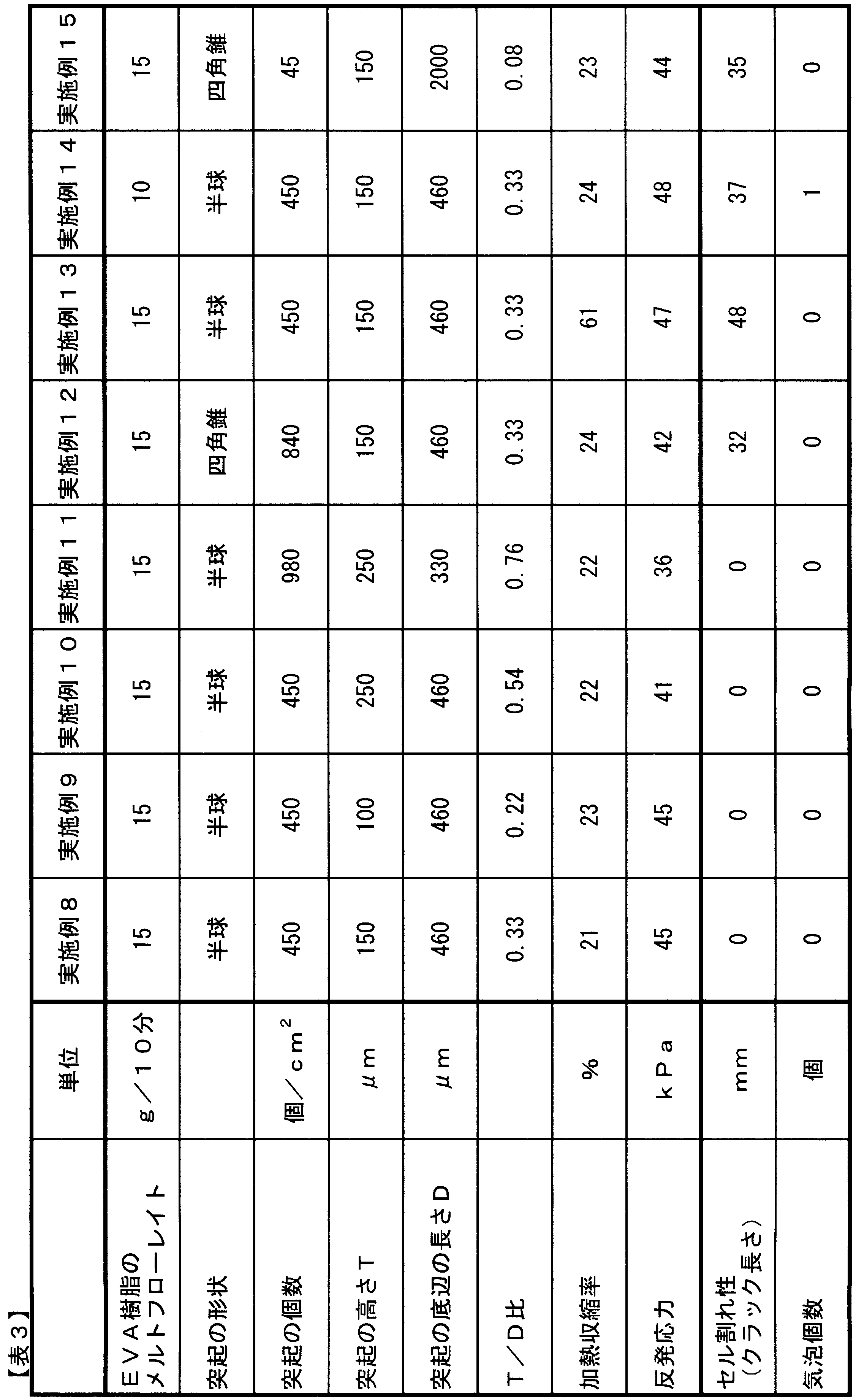
- the heat shrinkage rate, rebound stress, cell cracking property during module production, and the number of bubbles of the obtained encapsulant sheet were evaluated.
- the results are shown in Table 3.
- the sheet was a sealing material sheet having a small sheet heat shrinkage ratio and having few cell cracks and bubbles during module production.
- Example 9 The embossing roller in step (c) was sealed in the same manner as in Example 8 except that the embossing roller was changed to an embossing roller having a pattern depth of 120 ⁇ m, a diameter of 460 ⁇ m, and 450 hemispherical concave engraving patterns / cm 2. A material sheet was created. As shown in Table 3, the obtained encapsulant sheet was a encapsulant sheet having a small sheet heat shrinkage ratio and few cell cracks and bubbles during module production.
- Example 10 The embossing roller in the step (c) was sealed in the same manner as in Example 8 except that the embossing roller was changed to an embossing roller having a pattern depth of 300 ⁇ m, a diameter of 460 ⁇ m, and 450 hemispherical concave engraving patterns / cm 2.
- a material sheet was created.
- the obtained encapsulant sheet was a encapsulant sheet having a small sheet heat shrinkage ratio and few cell cracks and bubbles during module production.
- Example 11 The embossing roller in the step (c) was sealed in the same manner as in Example 8 except that the embossing roller was changed to an embossing roller having a pattern depth of 300 ⁇ m and a diameter of 330 ⁇ m and a hemispherical concave engraving pattern of 980 pieces / cm 2.
- a material sheet was created.
- the obtained encapsulant sheet was a encapsulant sheet having a small sheet heat shrinkage ratio and few cell cracks and bubbles during module production.
- Example 12 In the same manner as in Example 8, except that the embossing roller in the step (c) was changed to an embossing roller having a pattern depth of 180 ⁇ m, an outer diameter of 460 ⁇ m and a rectangular pyramid-shaped concave engraving pattern of 840 pieces / cm 2.
- a sealing material sheet was prepared. As shown in Table 3, the obtained encapsulant sheet was a encapsulant sheet having a small sheet heat shrinkage rate and few bubbles, although some cell cracking during module production occurred.
- Example 13 A sealing material sheet was prepared in the same manner as in Example 8 except that the annealing was not performed and the sheet surface temperature was heated to 90 ° C. with an infrared heater and embossing was performed. As shown in Table 3, the obtained encapsulant sheet was a encapsulant sheet with a small number of bubbles, although the sheet had a large heat shrinkage rate and cell cracking occurred slightly during module production.
- Example 14 A sealing material sheet was prepared in the same manner as in Example 8 except that the EVA resin was changed to an EVA resin having a melt flow rate of 10 g / 10 min. As shown in Table 3, the obtained encapsulant sheet was a encapsulant sheet having a small sheet heat shrinkage rate and few bubbles, although some cell cracking during module production occurred.
- Example 15 In the same manner as in Example 8, except that the embossing roller in the step (c) was changed to an embossing roller having a pattern depth of 180 ⁇ m, an outer peripheral diameter of 2000 ⁇ m, and 45 pyramidal concave engraving patterns / cm 2.
- a sealing material sheet was prepared. As shown in Table 3, the obtained encapsulant sheet was a encapsulant sheet with a small number of bubbles, although the sheet heat shrinkage rate was small and cell cracking during module production was slightly generated.
- the sealing material sheet which implemented by annealing method by the method similar to Example 8 was created, and it used for evaluation.
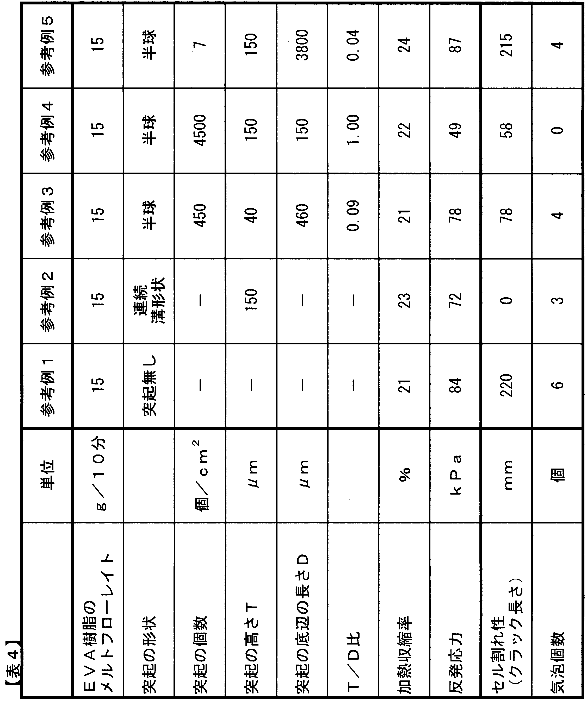
- the obtained encapsulant sheet was a encapsulant sheet in which the heat shrinkage rate of the sheet was small, but a large number of cell cracks and bubbles were generated during module production.
- Example 8 except that the embossing roller in the step (c) was changed to an embossing roller having a pattern depth of 180 ⁇ m and an engraving pattern of a semicircular groove (groove width 460 ⁇ m) continuous in the rotation direction of the roll.
- a sealing material sheet was prepared in the same manner.
- the obtained encapsulant sheet was a encapsulant sheet having a small sheet heat shrinkage rate and few cell cracks during module production, but having many bubbles.
- the embossing roller in the step (c) was sealed in the same manner as in Example 8 except that the embossing roller was changed to an embossing roller having a pattern depth of 180 ⁇ m and a diameter of 150 ⁇ m and a hemispherical concave engraving pattern of 4500 pieces / cm 2.
- a material sheet was created.
- the obtained encapsulant sheet was a encapsulant sheet having a small sheet heat shrinkage rate and a small number of bubbles, but many cell cracks during module production.
- step (c) The embossing roller in step (c) was sealed in the same manner as in Example 8 except that the embossing roller was changed to an embossing roller having a pattern depth of 180 ⁇ m, a diameter of 3800 ⁇ m, and 7 hemispherical concave engraving patterns / cm 2.
- a material sheet was created. As shown in Table 4, the obtained encapsulant sheet had a small sheet heat shrinkage rate, but was a encapsulant sheet with many cell cracks and bubbles during module production.
Landscapes
- Engineering & Computer Science (AREA)
- Mechanical Engineering (AREA)
- Shaping Of Tube Ends By Bending Or Straightening (AREA)
Abstract
Description
工程(a): 加熱により溶融した樹脂組成物をシート状に成形し、次いで冷却することで工程シートを得る工程
工程(b): 前記工程(a)で得られた工程シートの少なくとも一方の表面を22~55秒間加熱し、この加熱中にこの表面の温度を、この表面部分を構成する樹脂組成物の融点以上の温度に到達させる工程
工程(c): 前記工程(b)において加熱された工程シートの表面を、(前記表面部分を構成する樹脂組成物の融点-10℃)~(前記表面部分を構成する樹脂組成物の融点+20℃)の温度にし、次いでこの表面にエンボスローラーを押し当て、この表面にエンボス形状を形成する工程
本発明の太陽電池封止材シートの製造方法は、下記の工程(a)、工程(b)および工程(c)をこの順番に行う。
工程(a): 加熱により溶融した樹脂組成物をシート状に成形し、次いで冷却することで工程シートを得る工程。
工程(b): 前記工程(a)で得られた工程シートの少なくとも一方の表面を22~55秒間加熱し、この加熱中にこの表面の温度を、この表面部分を構成する樹脂組成物の融点以上の温度に到達させる工程。
工程(c): 前記工程(b)において加熱された工程シートの表面を、(前記表面部分を構成する樹脂組成物の融点-10℃)~(前記表面部分を構成する樹脂組成物の融点+20℃)の温度にし、次いでこの表面にエンボスローラーを押し当て、この表面にエンボス形状を形成する工程。
まず、工程(a)について説明する。工程(a)は、原料樹脂をシート状に成形し、これを冷却して工程シートを得る工程である。以下、工程(a)を製膜工程と呼ぶ。
次に工程(b)について説明する。工程(b)の目的は、製膜工程で成形された工程シートが有する残留歪みを除去し、工程シートの加熱収縮を低減させることである。工程(b)では、アニール炉15の中に設置されたヒータ16で加熱しながら、複数の搬送ローラー17の上に工程シートを通すなどの方法が挙げられる。以下、工程(b)をアニール工程と呼ぶ。
次に工程(c)について説明する。工程(c)は、アニール工程での加熱により高温状態となった工程シートにエンボス加工を施し、工程シート表面にエンボス形状を形成する工程である。工程(c)には、工程シートにエンボス形状を形成するためのエンボスローラー20、エンボス対向ローラー19、および冷却ローラー21が設けられている。以後、この工程(c)をエンボス加工工程と呼ぶ。
次に太陽電池封止材シートについて説明する。封止材シートは、表面に高さ60~300μmの独立した突起を有しているのが好ましい。封止材シートの表面に独立した高さ60μm以上の突起を有することにより、太陽電池モジュールを製造する際の真空ラミネート時に、封止材シートと太陽電池セルとの間に残留した空気を多方向から効率的に除去し、気泡の発生を抑制できる。さらに、封止材シートの太陽電池セルへの押し圧力を分散させ、セル割れの発生を抑制することができる。封止材シート表面の形状が独立した突起ではなく、連続した溝形状であると、溝に直行する方向への脱気が不十分となり、残留した空気が気泡となる。また、突起の高さが300μm以下であると、真空ラミネート時の突起の頂部への荷重の集中が抑制され、太陽電池セルが割れることを防止できる。ここで、「独立した突起」とは、突起の底面に着目したときに、後述する底辺の長さDが70~6000μmの範囲の突起である。
次に封止材シートを構成する樹脂組成物について説明する。なお、少なくとも突起が形成される側の表面部分を構成する樹脂組成物が、以下に説明する樹脂組成物の組成等を満たすことが好ましい。もちろん、工程シートを構成する全ての樹脂組成物が、以下に説明する樹脂組成物の組成等を満たしていることがより好ましい。
太陽電池モジュールは、受光面保護材と、裏面保護材と、この受光面保護剤と裏面保護材との間に配置され、封止材シートにより太陽電池セルが封止された層と、で構成されている。ここで使用される封止材シートとしては、本発明の製造方法により得られた封止材シートを使用してもよいし、前述した表面に独立した突起を有する封止材シートを使用してもよい。
成形した封止材シートを、幅方向で任意の20点の厚みを測定し、平均厚みを求めた。測定器は、ミツトヨ社製 シックネスゲージ(547-301型)を使用した。封止材シートの厚みは、封止材シートの片面のみに突起が形成されている場合は、突起の頂点から、突起を有する面とは反対側の面までの距離を測定した。封止材シートの両面に突起が形成されている場合は、一方の面の突起の頂点から、反対面の突起の頂点までの距離を測定した。
製造時のシートの走行方向(以下、MD方向と略する)とは直角の方向(幅方向)に、突起の頂部を通過するよう封止材シートを切断した。切断した封止材シートの厚み方向断面を実体顕微鏡でシートの全幅に渡って観察した。
封止材シートの片面に突起がある場合、封止材シートの突起のある側の面をA面、突起のない側の面をB面とする。図3に示すように、A面の突起の頂点からB面までの距離をTmax、A面の突起のない部分からB面までの距離をTminとする。そして、突起の高さTを式(i)で計算した。
・T(μm)=Tmax-Tmin ・・・(i)
封止材シートの両面に突起がある場合、封止材シートの一方の面をA面、もう一方の面をB面とする。図4に示すように、A面の突起の頂点からB面の突起のない部分までの距離をTAmax、B面の突起の頂点からA面の突起のない部分までの距離をTBmax、A面の突起のない部分からB面の突起のない部分までの距離をTminとする。そして、A面の突起の高さTAを式(ii)で、B面の突起の高さTBを式(iii)で計算した。
・TA(μm)=TAmax-Tmin ・・・(ii)
・TB(μm)=TBmax-Tmin ・・・(iii)。
エンボスローラーの表面を、JIS B0601(2001)に準拠し、基準長さ20mm、荷重0.75mN、測定速度0.3mm/sの測定条件で測定した。測定は、ミツトヨ社製 小形表面粗さ測定器 SJ401を用い、円錐60°、先端曲率半径2μmのダイヤモンド触針を用いて測定した。この測定値を、エンボスローラーの模様深さPz値(μm)とした。
上記(2)で測定した突起高さT(μm)(または、突起高さTA(μm)若しくは突起高さTB(μm))を、上記(3)で測定したエンボスローラーの模様深さPzで除した値をエンボス転写率とした。
・エンボス転写率(%)=T/Pz×100。
封止材シートから一辺が120mmの平面正方形状の試験片を切り出した。この試験片上に、製造時のTD方向中央部に、100mmの間隔をあけて二本の平行なTD方向の直線(5cm)を引いた。そして、各直線を6等分する位置(それぞれ5カ所)に印を付した。
次に、試験片を80℃に加熱した温水中に60秒間放置した。封止材シートの比重が小さく、封止材シートが温水の表面に浮ぶ場合は、その浮かんだままの状態で放置した。封止材シートの比重が大きく、封止材シートが温水の中に沈む場合は、その沈んだままの状態で放置した。60秒経過してから、試験片を温水から取り出し、20℃の常温水中に10秒間浸漬させ冷却した後、シート表面の水分を取り除いた。
試験片上に引いた一方の直線に付した5カ所の各印から、もう一方の直線に付した対向する各印までの間隔A(mm)をノギスで測定し、下記式に基づいて加熱収縮率を算出し、5カ所の平均値を求めた。
・加熱収縮率(%)=(100-A)/100×100。
樹脂組成物を、JIS K7210(1999)「プラスチック-熱可塑性プラスチックのメルトマスフローレイト(MFR)およびメルトボリュームフローレイト(MVR)の試験方法」に準拠し、温度190℃、加重2.16kgの試験条件で測定した。
シートの突起を有する面を実体顕微鏡で観察し、底辺長さ(D)を測定する。突起の底面の形状が三角形や六角形などの多角形や、楕円形である場合は、前記の形状を包含する最小真円の直径を測定した。
封止材シートから一辺が180mmの平面正方形状の試験片を2枚切り出した。多結晶太陽電池セル(3バスバー、サイズ156mm角、厚み200μm)に、インターコネクタ(厚み280μm、幅2mm)を半田付けし、インターコネクタ付きの太陽電池セルを作成した。ガラス板(サイズ180mm角、厚み3mm)と、ポリエステル製太陽電池バックシート(サイズ180mm角、厚み240μm)を用意した。ガラス板の上に、封止材シート、太陽電池セル、封止材シート、バックシートの順で積層した。この際、封止材シートの突起を有する面が太陽電池セルに接するようにして積層した。この積層体を、温度145℃、真空引き30秒、プレス1分、圧力保持10分の条件で真空ラミネートを行い、太陽電池モジュールを製作した。得られた太陽電池モジュールを太陽電池EL画像検査装置によって、発光画像を撮影し、セル割れ部の総クラックの長さ(mm)を測定した。この試験を3回繰り返し総クラック長さの平均値を求めた。
上記(8)で製作した太陽電池モジュール中の気泡個数を目視により数えた。3回分の試験の平均値を求めた。
封止材シートから一辺が120mmの平面正方形状の試験片を切り出した。次いで、カトーテック社製 圧縮試験機 KES FB-3を用い、試験片の突起を有する面から、直径16mmの扁平加圧端子により、速度20μm/秒で封止材シートを加圧し、厚み方向に100μm加圧した際のシートの反発応力(kPa)を測定した。この試験を3回繰り返し反発応力の平均値を求めた。
図1に示した製造方法に従って太陽電池封止材シートを作成した
工程(a):製膜工程
押出機11として2軸押出機を用い、EVA(酢酸ビニル含有量:28質量%、メルトフローレイト:15g/10分、融点:71℃)100質量部、t-ブチルパーオキシ-2-エチルヘキシルモノカーボネート(1時間半減期温度:119℃)0.7質量部、トリアリルイソシアヌレート0.3質量部、γ-メタクリロキシプロピルトリメトキシシラン0.2質量部、2-ヒドロキシ-4-メトキシベンゾフェノン0.3質量部、ビス(1,2,2,6,6-ペンタメチル-4-ピペリジル)セバケート0.1質量部からなる樹脂組成物を80℃に設定した押出機11に供給して溶融混練した。混練した樹脂組成物を押出機11に接続された105℃に保持されたTダイ12から押出した。なお用いたTダイのリップ幅は1300mm、リップ間隙は0.8mmであった。
このように押出した樹脂組成物を20℃に保持されたポリシングローラー13a、13b、13cによって冷却固化し、シート状にした。なお、Tダイから吐出された時点の工程シートの温度は107℃であった。またこのときの工程シートの幅は1150mm、厚みは450μm、搬送速度は10m/分であった。
次に、アニール処理を表1に記載の条件にて実施した。
加熱にはセラミックヒータ16を用い、搬送ローラー17には直径150mmで表面に“テフロン(登録商標)”コーティングした金属ローラーを、ローラーの中心間距離が200mmとなるような間隔で設置したものを用いた。アニール炉15は、SUS製の筐体に断熱材を巻きつけたものを用いた。また、アニール炉15の入り口下部と出口下部より、風速1m/secで、熱風を吹き込んだ。
表1に記載の条件に従い、エンボス加工をアニール処理に連続して実施した。
エンボス加工は、アニール炉から搬送された工程シートを、模様深さが120μmのエンボスローラー20と、硬度75°のシリコンゴムを厚み10mm巻きつけたエンボス対向ローラー19との間を通すことで実施した。
工程(b)における熱風の温度を87℃、ヒータ温度を320℃、炉内滞留時間を29秒とした以外は、実施例1と同じ方法で封止材シートを作成した。工程シートの表面温度が下がったため、加熱収縮率が少し大きくなり、またエンボス転写率が少し低くなったが、実施例1と同様に加熱収縮率が非常に小さく、かつエンボス模様が明瞭に転写された太陽電池封止材シートが得られた。
工程(b)における熱風の温度を80℃、ヒータ温度を300℃、炉内滞留時間を30秒、線圧力を450N/cmとした以外は、実施例1と同じ方法で封止材シートを作成した。工程シートの表面温度がさらに下がったため、加熱収縮率が少し大きくなり、またエンボス転写率が少し低くなったが、実施例1と同様に加熱収縮率が非常に小さく、かつエンボス模様が明瞭に転写された太陽電池封止材シートが得られた。
工程(c)における線圧力を200N/cmとした以外は実施例3と同じ方法で封止材シートを作成した。エンボス転写率が少し低くなったが、実施例3と同様にエンボス模様が明瞭に転写された太陽電池封止材シートが得られた。
工程(b)における熱風温度を110℃、炉内滞留時間を27秒とし、工程(c)における線圧力を200N/cmとした以外は実施例1と同様の方法でシートを作成した。工程シートの表面温度が上がったため、加熱収縮率が非常に小さくなり、エンボス転写率も明瞭な太陽電池封止材シートが得られた。
工程(c)におけるエンボスローラーへの抱き付け角を45°とした以外は、実施例5と同じ方法で封止材シートを作成した。抱き付け角が浅くなったことにより、エンボス転写率が若干浅くなったが、良好な外観を有するシートであった。
工程(b)における工程シートの搬送速度を7m/min、熱風温度を110℃、ヒータ温度を300℃、炉内滞留時間を39秒とし、工程(c)における線圧力を120N/cmとした以外は実施例1と同様の方法で封止材シートを作成した。工程シートの加熱時間が長くなり、表面温度が高くなったため、加熱収縮率が大きく低減し、線圧力が低くても明瞭なエンボス形状のシートを作成することができた。
表2に示した条件を適用した以外は、実施例1と同様の方法で太陽電池封止材シートを作成した。
図2に示す従来の製造方法にてTダイから押し出した直後にエンボス加工を実施し、次いでアニール処理を行った。アニール処理装置は実施例1と同様のものとし、Tダイ直後のエンボスローラー13b’に模様深さが120μmのローラーを用いた。

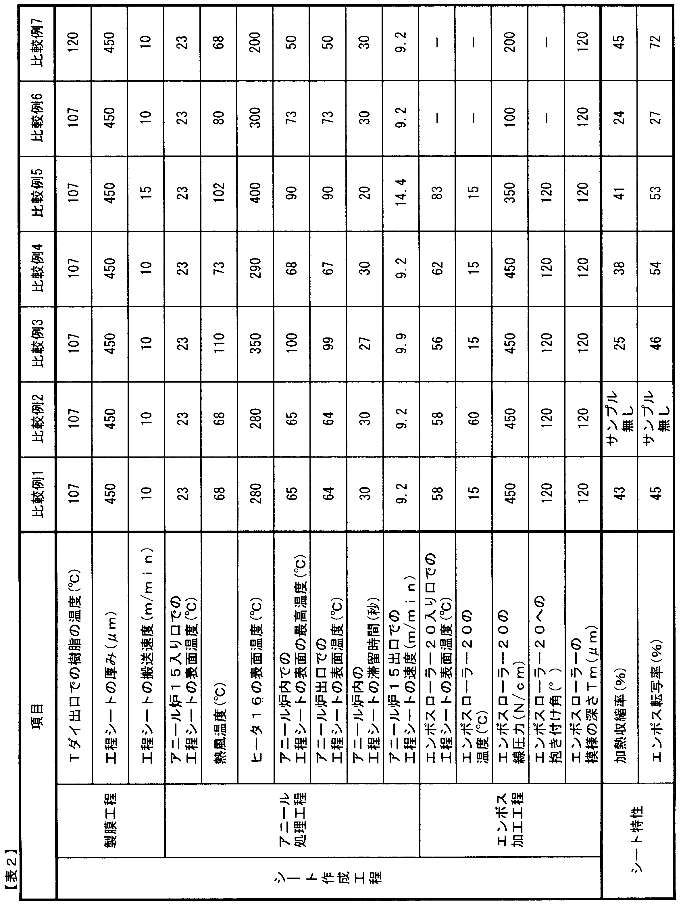
表1に示すとおり、実施例1~7で作成した太陽電池封止材シートは、加熱収縮率が小さく、しかもエンボス転写率が高く、エンボス形状が明確に転写されていた。
これらの太陽電池封止材シートを用いて、太陽電池モジュールを従来公知の方法で作成したところ、モジュール作成時に、セルがずれたり、セルが割れたり、気泡が混入してしまうような不具合は発生しなかった。
比較例2では、エンボスローラーに工程シートが巻き付き、サンプルを得ることができなかった。
比較例5では、アニール処理時間が短いため、太陽電池封止材シートの加熱収縮を十分低減することができなかった。
比較例6,7では、ポリシングローラーでエンボス形状を付与したためエンボス形状は明瞭であったが、加熱収縮を低減しようとすると、エンボス形状が崩れてしまい、エンボス形状を保持しようとすると加熱収縮が低減できなかった。
工程(a):製膜工程
EVA(酢酸ビニル含有量:28質量%、メルトフローレイト:15g/10分(190℃)、融点:71℃)100質量部、t-ブチルパーオキシ-2-エチルヘキシルモノカーボネート(1時間半減期温度:119℃)0.7質量部、トリアリルイソシアヌレート0.3質量部、γ-メタクリロキシプロピルトリメトキシシラン0.2質量部、2-ヒドロキシ-4-メトキシベンゾフェノン0.3質量部、ビス(1,2,2,6,6-ペンタメチル-4-ピペリジル)セバケート0.1質量部からなる樹脂組成物を80℃に設定した2軸押出機に供給して溶融混練した。混練した樹脂組成物を、2軸押出機に接続され105℃に保持されたTダイからを押出した。なおTダイのリップ幅は1300mm、リップ間隙は0.8mmであった。
アニール処理は、表面温度を350℃に設定したセラミックヒータを設置し、直径150mmで表面に“テフロン(登録商標)”コーティングした金属ローラーを、ローラーの中心間距離が250mmとなるような間隔で設置した、SUS製の筐体に断熱材を巻きつけたアニール炉内を通すことで行った。また、炉の入り口下部と出口下部より、風速1m/secで、熱風を吹き込んだ。
エンボス加工は、アニール炉から取り出したシートを、模様深さが180μm、直径460μmで半球形状の凹型の彫刻模様を450個/cm2有するエンボスローラーと、硬度75°のシリコンゴムを厚み10mm巻きつけた対向ローラーとの間を通すことで実施した。
アニール炉入り口でのシート表面温度:23℃
熱風温度:93℃
アニール炉内でのシート表面の最高温度:90℃
アニール炉出口でのシート表面温度:90℃
アニール炉内のシート滞留時間:28秒
アニール炉15出口でのシート速度:9.6m/min
エンボスローラー入り口でのシート表面温度:78℃
エンボスローラー温度:15℃
エンボスローラーの線圧力:350N/cm
エンボスローラーへの抱き付け角:120°。
工程(c)におけるエンボスローラーを、模様深さが120μm、直径460μmで半球形状の凹型の彫刻模様を450個/cm2有するエンボスローラーに変更した以外は、実施例8と同様の方法で封止材シートを作成した。
得られた封止材シートは表3に示すとおり、シート加熱収縮率が小さく、モジュール製造時のセル割れ、気泡の少ない封止材シートであった。
工程(c)におけるエンボスローラーを、模様深さが300μm、直径460μmで半球形状の凹型の彫刻模様を450個/cm2有するエンボスローラーに変更した以外は、実施例8と同様の方法で封止材シートを作成した。
得られた封止材シートは表3に示すとおり、シート加熱収縮率が小さく、モジュール製造時のセル割れ、気泡の少ない封止材シートであった。
工程(c)におけるエンボスローラーを、模様深さが300μm、直径330μmで半球形状の凹型の彫刻模様を980個/cm2有するエンボスローラーに変更した以外は、実施例8と同様の方法で封止材シートを作成した。
得られた封止材シートは表3に示すとおり、シート加熱収縮率が小さく、モジュール製造時のセル割れ、気泡の少ない封止材シートであった。
工程(c)におけるエンボスローラーを、模様深さが180μm、外周直径460μmで四角錐形状の凹型の彫刻模様を840個/cm2有するエンボスローラーに変更した以外は、実施例8と同様の方法で封止材シートを作成した。
得られた封止材シートは表3に示すとおり、モジュール製造時のセル割れは若干発生するものの、シート加熱収縮率が小さく、気泡の少ない封止材シートであった。
アニール処理を実施せず、赤外線ヒータによりシート表面温度を90℃に加熱し、エンボス加工を実施した以外は、実施例8と同様の方法で封止材シートを作成した。
得られた封止材シートは表3に示すとおり、シートの加熱収縮率が大きく、モジュール製造時のセル割れは若干発生するものの、気泡の少ない封止材シートであった。
EVA樹脂をメルトフローレイト10g/10分のEVA樹脂に変更した以外は、実施例8と同様の方法で封止材シートを作成した。得られた封止材シートは表3に示すとおり、モジュール製造時のセル割れは若干発生するものの、シート加熱収縮率が小さく、気泡の少ない封止材シートであった。
工程(c)におけるエンボスローラーを、模様深さが180μm、外周直径2000μmで四角錐形状の凹型の彫刻模様を45個/cm2有するエンボスローラーに変更した以外は、実施例8と同様の方法で封止材シートを作成した。
得られた封止材シートは表3に示すとおり、シート加熱収縮率が小さく、モジュール製造時のセル割れは若干発生するものの、気泡の少ない封止材シートであった。
エンボス加工を実施しない他は、実施例8と同様の方法でアニール処理まで実施した封止材シートを作成し評価に供した。
得られた封止材シートは表4に示すとおり、シートの加熱収縮率は小さいが、モジュール製造時のセル割れ、気泡が大量に発生する封止材シートであった。
工程(c)におけるエンボスローラーを、模様深さが180μmで、ロールの回転方向に連続した半円形状の溝(溝幅460μm)の彫刻模様を有するエンボスローラーに変更した以外は、実施例8と同様の方法で封止材シートを作成した。
得られた封止材シートは表4に示すとおり、シート加熱収縮率が小さく、モジュール製造時のセル割れは少ないが、気泡の多い封止材シートであった。
工程(c)におけるエンボスローラーを、模様深さが50μm、直径460μmで半球形状の凹型の彫刻模様を450個/cm2有するエンボスローラーに変更した以外は、実施例8と同様の方法で封止材シートを作成した。
得られた封止材シートは表4に示すとおり、シート加熱収縮率は小さいが、モジュール製造時のセル割れ、気泡の多い封止材シートであった。
工程(c)におけるエンボスローラーを、模様深さが180μm、直径150μmで半球形状の凹型の彫刻模様を4500個/cm2有するエンボスローラーに変更した以外は、実施例8と同様の方法で封止材シートを作成した。
得られた封止材シートは表4に示すとおり、シート加熱収縮率は小さく、気泡は少ないが、モジュール製造時のセル割れの多い封止材シートであった。
工程(c)におけるエンボスローラーを、模様深さが180μm、直径3800μmで半球形状の凹型の彫刻模様を7個/cm2有するエンボスローラーに変更した以外は、実施例8と同様の方法で封止材シートを作成した。
得られた封止材シートは表4に示すとおり、シート加熱収縮率は小さいが、モジュール製造時のセル割れ、および気泡の多い封止材シートであった。
11 2軸押出機
12 ダイ
13a ポリシングローラー(表面に彫刻加工なし)
13b ポリシングローラー(表面に彫刻なし)
13b’エンボスローラー(表面に彫刻加工あり)
13c ポリシングローラー(表面に彫刻加工なし)
14 ニップローラー
15 アニール炉
16 ヒータ
17 搬送ローラー
18 シート取り出しローラー
19 エンボス対向ローラー
20 エンボスローラー
21 冷却ローラー
31 ギヤポンプ
32 シート搬送方向
33 非接触式赤外線温度計
Claims (11)
- 下記の工程(a)、工程(b)および工程(c)をこの順番に行う、太陽電池封止材シートの製造方法。
工程(a): 加熱により溶融した樹脂組成物をシート状に成形し、次いで冷却することで工程シートを得る工程
工程(b): 前記工程(a)で得られた工程シートの少なくとも一方の表面を22~55秒間加熱し、この加熱中にこの表面の温度を、この表面部分を構成する樹脂組成物の融点以上の温度に到達させる工程
工程(c): 前記工程(b)において加熱された工程シートの表面を、(前記表面部分を構成する樹脂組成物の融点-10℃)~(前記表面部分を構成する樹脂組成物の融点+20℃)の温度にし、次いでこの表面にエンボスローラーを押し当て、この表面にエンボス形状を形成する工程 - 前記工程(c)において、前記エンボスローラーで前記工程シートの表面を押し当てる際に、この表面にかかる線圧力を150~500N/cmにする、請求項1の太陽電池封止材シートの製造方法。
- 前記工程(c)において、前記エンボスローラーで前記工程シートの表面を押し当てる際に、このエンボスローラーの表面温度を(前記表面部分を構成する樹脂組成物の融点-20℃)以下にする、請求項1または2の太陽電池封止材シートの製造方法。
- 前記工程(a)において、単軸または2軸押出機を用いて前記加熱により溶融した樹脂組成物をダイから押し出してシート状に成形する、請求項1~3のいずれかの太陽電池封止材シートの製造方法。
- 前記表面部分を構成する樹脂組成物が、ポリオレフィン系樹脂と有機過酸化物を含む、請求項1~4のいずれかの太陽電池封止材シートの製造方法。
- 請求項1~5のいずれかの製造方法によって得られた太陽電池封止材シートであって、
前記表面部分を構成する樹脂組成物がポリオレフィン系樹脂を含み、
前記エンボス形状が形成された表面が、高さ60~300μmの独立した突起を40~2300個/cm2有し、かつ、この独立した突起の高さ(T)と底辺長さ(D)との比(T/D)が0.05~0.80である、太陽電池封止材シート。 - 前記太陽電池封止材シートを80℃の温水中に1分間放置した際に、この封止材シートのシート流れ方向の加熱収縮率が30%以下である、請求項6の太陽電池封止材シート。
- 前記独立した突起の形状が、半球状および/または四角錐状である、請求項6または7の太陽電池封止材シート。
- 前記太陽電池封止材シートの前記突起を有する面を、この封止材シートの厚み方向に100μm圧縮した際に、シートの反発応力が70kPa以下である、請求項6~8のいずれかの太陽電池封止材シート。
- 前記太陽電池封止材シートの突起を有する面が、さらに、高さ1~15μmの突起を有する、請求項6~9のいずれかの太陽電池封止材シート。
- 受光面保護材と、
裏面保護材と、
この受光面保護材と裏面保護材との間に配置され、請求項6~10のいずれかの太陽電池封止材シートにより太陽電池セルが封止された層と、
で構成された、太陽電池モジュール。
Priority Applications (2)
| Application Number | Priority Date | Filing Date | Title |
|---|---|---|---|
| KR1020137024913A KR20140010961A (ko) | 2011-03-31 | 2012-03-23 | 태양 전지 밀봉재 시트의 제조 방법 |
| CN201280014497.1A CN103442880B (zh) | 2011-03-31 | 2012-03-23 | 太阳能电池密封片材的制造方法 |
Applications Claiming Priority (4)
| Application Number | Priority Date | Filing Date | Title |
|---|---|---|---|
| JP2011-077719 | 2011-03-31 | ||
| JP2011077719 | 2011-03-31 | ||
| JP2011077718 | 2011-03-31 | ||
| JP2011-077718 | 2011-03-31 |
Publications (1)
| Publication Number | Publication Date |
|---|---|
| WO2012133196A1 true WO2012133196A1 (ja) | 2012-10-04 |
Family
ID=46930919
Family Applications (1)
| Application Number | Title | Priority Date | Filing Date |
|---|---|---|---|
| PCT/JP2012/057531 Ceased WO2012133196A1 (ja) | 2011-03-31 | 2012-03-23 | 太陽電池封止材シートの製造方法 |
Country Status (3)
| Country | Link |
|---|---|
| KR (1) | KR20140010961A (ja) |
| CN (1) | CN103442880B (ja) |
| WO (1) | WO2012133196A1 (ja) |
Cited By (3)
| Publication number | Priority date | Publication date | Assignee | Title |
|---|---|---|---|---|
| CN111645312A (zh) * | 2019-03-04 | 2020-09-11 | 世联株式会社 | 压花加工模具、压花加工装置以及压花加工方法 |
| CN113214556A (zh) * | 2021-05-20 | 2021-08-06 | 深圳市金露兴科技有限公司 | 一种防护级密封薄膜配方及其生产工艺 |
| US11167465B2 (en) | 2017-09-26 | 2021-11-09 | Davis-Standard, Llc | Casting apparatus for manufacturing polymer film |
Families Citing this family (7)
| Publication number | Priority date | Publication date | Assignee | Title |
|---|---|---|---|---|
| DE102014103729A1 (de) * | 2014-03-19 | 2015-09-24 | Ensinger Gmbh | Verfahren zur Herstellung eines Isolierstegs |
| KR20170101257A (ko) * | 2015-02-04 | 2017-09-05 | 미쓰이 가가쿠 토세로 가부시키가이샤 | 태양 전지 밀봉용 필름, 태양 전지 밀봉용 필름 롤, 및 태양 전지 모듈의 제조 방법 |
| CN105034346B (zh) * | 2015-06-19 | 2017-06-16 | 河北贵航鸿图汽车零部件有限公司 | 一种汽车密封条的表面花纹成型装置 |
| CN108297490A (zh) * | 2017-01-13 | 2018-07-20 | 上海众邦制版科技有限公司 | 一种墙纸压纹辊制作方法 |
| CN108621353A (zh) * | 2017-03-24 | 2018-10-09 | 阿特斯阳光电力集团有限公司 | 光伏封装胶膜制备装置 |
| JP7106416B2 (ja) * | 2018-10-01 | 2022-07-26 | 東レ株式会社 | エンボス成形用シリコーンゴムローラー、それを用いたプラスチックフィルムの製造方法および製造装置、ならびに表面保護フィルム |
| CN113910746B (zh) * | 2021-10-18 | 2023-10-27 | 江西弘德智信科创有限公司 | 基于工业机器人的光伏组件层压定位装置 |
Citations (6)
| Publication number | Priority date | Publication date | Assignee | Title |
|---|---|---|---|---|
| JP2010222545A (ja) * | 2009-03-25 | 2010-10-07 | Asahi Kasei E-Materials Corp | 樹脂封止シートの製造方法及び樹脂封止シート |
| JP2010232311A (ja) * | 2009-03-26 | 2010-10-14 | Sekisui Chem Co Ltd | 太陽電池用封止シート |
| JP2011020375A (ja) * | 2009-07-16 | 2011-02-03 | C I Kasei Co Ltd | 低収縮性樹脂フィルムの製造方法 |
| JP2011077256A (ja) * | 2009-09-30 | 2011-04-14 | Sekisui Chem Co Ltd | 太陽電池用接着シートの製造方法 |
| JP2011116014A (ja) * | 2009-12-02 | 2011-06-16 | Asahi Kasei E-Materials Corp | 太陽電池封止シートの製造方法 |
| JP2011151284A (ja) * | 2010-01-25 | 2011-08-04 | C I Kasei Co Ltd | 太陽電池モジュール用封止フィルムおよびその製造方法 |
Family Cites Families (2)
| Publication number | Priority date | Publication date | Assignee | Title |
|---|---|---|---|---|
| EP1930953A4 (en) * | 2005-09-30 | 2014-08-13 | Toray Industries | SEALING FILM FOR A SOLAR CELL MODULE AND SOLAR CELL MODULE |
| CN101826568B (zh) * | 2009-03-03 | 2016-06-22 | C.I.化成株式会社 | 低伸缩性树脂膜及其制造方法以及制造装置 |
-
2012
- 2012-03-23 WO PCT/JP2012/057531 patent/WO2012133196A1/ja not_active Ceased
- 2012-03-23 CN CN201280014497.1A patent/CN103442880B/zh not_active Expired - Fee Related
- 2012-03-23 KR KR1020137024913A patent/KR20140010961A/ko not_active Withdrawn
Patent Citations (6)
| Publication number | Priority date | Publication date | Assignee | Title |
|---|---|---|---|---|
| JP2010222545A (ja) * | 2009-03-25 | 2010-10-07 | Asahi Kasei E-Materials Corp | 樹脂封止シートの製造方法及び樹脂封止シート |
| JP2010232311A (ja) * | 2009-03-26 | 2010-10-14 | Sekisui Chem Co Ltd | 太陽電池用封止シート |
| JP2011020375A (ja) * | 2009-07-16 | 2011-02-03 | C I Kasei Co Ltd | 低収縮性樹脂フィルムの製造方法 |
| JP2011077256A (ja) * | 2009-09-30 | 2011-04-14 | Sekisui Chem Co Ltd | 太陽電池用接着シートの製造方法 |
| JP2011116014A (ja) * | 2009-12-02 | 2011-06-16 | Asahi Kasei E-Materials Corp | 太陽電池封止シートの製造方法 |
| JP2011151284A (ja) * | 2010-01-25 | 2011-08-04 | C I Kasei Co Ltd | 太陽電池モジュール用封止フィルムおよびその製造方法 |
Cited By (4)
| Publication number | Priority date | Publication date | Assignee | Title |
|---|---|---|---|---|
| US11167465B2 (en) | 2017-09-26 | 2021-11-09 | Davis-Standard, Llc | Casting apparatus for manufacturing polymer film |
| US11173644B2 (en) | 2017-09-26 | 2021-11-16 | Davis-Standard, Llc | Casting apparatus for manufacturing polymer film |
| CN111645312A (zh) * | 2019-03-04 | 2020-09-11 | 世联株式会社 | 压花加工模具、压花加工装置以及压花加工方法 |
| CN113214556A (zh) * | 2021-05-20 | 2021-08-06 | 深圳市金露兴科技有限公司 | 一种防护级密封薄膜配方及其生产工艺 |
Also Published As
| Publication number | Publication date |
|---|---|
| KR20140010961A (ko) | 2014-01-27 |
| CN103442880B (zh) | 2016-04-27 |
| CN103442880A (zh) | 2013-12-11 |
Similar Documents
| Publication | Publication Date | Title |
|---|---|---|
| CN103442880B (zh) | 太阳能电池密封片材的制造方法 | |
| JP2012214050A (ja) | 太陽電池封止材シートの製造方法、および、太陽電池モジュール | |
| CN103650161B (zh) | 太阳能电池用背板 | |
| CN102438963B (zh) | 层叠体形成用乙烯-不饱和酯共聚物薄膜 | |
| EP2645424B1 (en) | Sheet for a sealing member of a solar cell, and method for preparing same | |
| JP6501906B2 (ja) | 太陽電池モジュール | |
| JP5421138B2 (ja) | 太陽電池モジュール用封止フィルムおよびその製造方法 | |
| JP5928092B2 (ja) | 太陽電池封止材シート、および、太陽電池モジュール | |
| CN104619492B (zh) | 太阳能电池密封片材和太阳能电池模块 | |
| JP6136444B2 (ja) | 押出シートの製造方法、太陽電池封止シート及び太陽電池モジュール | |
| JP5741775B2 (ja) | シートの熱処理方法およびシートの熱処理装置 | |
| JP2012079988A (ja) | 封止材シート及び太陽電池モジュール | |
| WO2017006982A1 (ja) | 架橋性樹脂膜及び架橋性樹脂膜の製造方法、太陽電池用封止膜及び太陽電池膜用封止膜の製造方法、基材貼り合せ用中間膜及び基材貼り合せ用中間膜の製造方法、太陽電池モジュール及び太陽電池モジュールの製造方法、積層体及び積層体の製造方法 | |
| JP2008117925A (ja) | 太陽電池用接着シート | |
| JP5727319B2 (ja) | ポリマーシート、太陽電池用保護シート及び太陽電池モジュール | |
| JP5176279B2 (ja) | 太陽電池モジュール用充填材シートの製造方法、および、太陽電池モジュールの製造方法 | |
| WO2012165351A1 (ja) | 共重合体、および当該共重合体を用いた太陽電池用封止材 | |
| JP2011066179A (ja) | 太陽電池モジュール用の封止材フィルムおよびその製造方法 | |
| JP2013159777A (ja) | 太陽電池封止材用樹脂 | |
| JPWO2016043235A1 (ja) | 太陽電池用封止材及び太陽電池モジュール | |
| JP6050652B2 (ja) | 太陽電池用ポリマーシートおよび太陽電池モジュール | |
| JP2012209474A (ja) | 太陽電池用接着シート及びその製造方法 | |
| TW201244915A (en) | Process for producing solar cell sealing sheet | |
| JP2011077256A (ja) | 太陽電池用接着シートの製造方法 | |
| JP2008096499A (ja) | 凹凸表面を有する機能性熱可塑性樹脂シートおよびその製造方法、ならびに転写フィルム |
Legal Events
| Date | Code | Title | Description |
|---|---|---|---|
| WWE | Wipo information: entry into national phase |
Ref document number: 201280014497.1 Country of ref document: CN |
|
| 121 | Ep: the epo has been informed by wipo that ep was designated in this application |
Ref document number: 12762942 Country of ref document: EP Kind code of ref document: A1 |
|
| ENP | Entry into the national phase |
Ref document number: 20137024913 Country of ref document: KR Kind code of ref document: A |
|
| NENP | Non-entry into the national phase |
Ref country code: DE |
|
| 122 | Ep: pct application non-entry in european phase |
Ref document number: 12762942 Country of ref document: EP Kind code of ref document: A1 |