WO2012133101A1 - 車体前部構造 - Google Patents
車体前部構造 Download PDFInfo
- Publication number
- WO2012133101A1 WO2012133101A1 PCT/JP2012/057323 JP2012057323W WO2012133101A1 WO 2012133101 A1 WO2012133101 A1 WO 2012133101A1 JP 2012057323 W JP2012057323 W JP 2012057323W WO 2012133101 A1 WO2012133101 A1 WO 2012133101A1
- Authority
- WO
- WIPO (PCT)
- Prior art keywords
- suspension member
- vehicle
- stopper
- floor
- suspension
- Prior art date
- Legal status (The legal status is an assumption and is not a legal conclusion. Google has not performed a legal analysis and makes no representation as to the accuracy of the status listed.)
- Ceased
Links
Images




Classifications
-
- B—PERFORMING OPERATIONS; TRANSPORTING
- B62—LAND VEHICLES FOR TRAVELLING OTHERWISE THAN ON RAILS
- B62D—MOTOR VEHICLES; TRAILERS
- B62D21/00—Understructures, i.e. chassis frame on which a vehicle body may be mounted
- B62D21/15—Understructures, i.e. chassis frame on which a vehicle body may be mounted having impact absorbing means, e.g. a frame designed to permanently or temporarily change shape or dimension upon impact with another body
- B62D21/152—Front or rear frames
- B62D21/155—Sub-frames or underguards
-
- B—PERFORMING OPERATIONS; TRANSPORTING
- B62—LAND VEHICLES FOR TRAVELLING OTHERWISE THAN ON RAILS
- B62D—MOTOR VEHICLES; TRAILERS
- B62D21/00—Understructures, i.e. chassis frame on which a vehicle body may be mounted
- B62D21/15—Understructures, i.e. chassis frame on which a vehicle body may be mounted having impact absorbing means, e.g. a frame designed to permanently or temporarily change shape or dimension upon impact with another body
- B62D21/152—Front or rear frames
-
- B—PERFORMING OPERATIONS; TRANSPORTING
- B62—LAND VEHICLES FOR TRAVELLING OTHERWISE THAN ON RAILS
- B62D—MOTOR VEHICLES; TRAILERS
- B62D25/00—Superstructure or monocoque structure sub-units; Parts or details thereof not otherwise provided for
- B62D25/08—Front or rear portions
- B62D25/082—Engine compartments
Definitions
- the present invention relates to a vehicle body front structure having a front side member having a kick portion, a floor side member connected to the rear end of the kick portion of the front side member, and a suspension member that supports the front suspension.
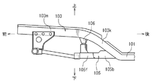
- the vehicle body described in Japanese Patent Application Laid-Open No. 2004-243785 has front side members 103 extending in the vehicle front-rear direction on both sides of an engine room (not shown) as shown in FIG.
- the front side member 103 has a substantially horizontal front side member main body portion 103m and a kick portion 103k that gently curves backward and downward from the rear end position of the engine room.
- a floor side member 101 extending in the vehicle front-rear direction on both sides in the width direction of the vehicle floor is connected to the rear end of the kick portion 103k of the front side member 103.
- the floor of the vehicle is made lower than the conventional structure. Therefore, the height difference between the front side member main body 103m and the floor side member 101, that is, the height dimension of the kick portion 103k of the front side member 103 is increased. Thereby, the strength of the kick portion 103k against the collision load when the vehicle collides forward is reduced. As a result, the amount of deformation of the kick portion 103k increases, and the amount of penetration of the front side member 103 into the passenger compartment can increase.
- the vehicle body front structure includes a front side member, a floor side member, a suspension member, and a stopper member.
- the front side member includes kick portions that extend in the vehicle front-rear direction on both sides in the width direction of the front portion of the vehicle and are inclined rearward and downward at the rear portion.
- the floor side member is connected to the rear end of the kick portion, and extends in the vehicle front-rear direction on both sides in the width direction of the vehicle floor.
- the suspension member has front both sides connected to the left and right front side members on the front side of the kick portion and rear both sides connected to the left and right floor side members and supports the front suspension.
- the stopper member is fixed to the vehicle floor on the rear side of the suspension member, forms a gap with the suspension member, and the suspension member comes into contact with the suspension member when the suspension member is retracted.
- the axial collision load applied to the front side member when the vehicle collides forward is transmitted to the floor side member via the kick portion.
- the collision load is applied to the suspension member from both front side portions of the kick portion of the front side member via the connecting portion.
- the suspension member moves backward and comes into contact with the stopper member, and the collision load is transmitted to the vehicle floor. Therefore, the collision load is dispersed and the collision load is not concentrated on the kick portion of the front side member. Thus, the collision load applied to the kick portion is reduced.
- the stopper member is disposed on the rear side of the suspension member is simple and economical. Further, since a gap is provided between the suspension member and the stopper member, it is possible to suppress the vibration of the suspension member from being transmitted from the stopper member to the vehicle floor.
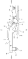
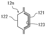
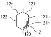
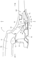
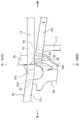
- FIG. 1 is a schematic plan view of a vehicle body front structure according to the present invention. It is the II-II sectional view taken on the line of FIG. It is the III-III arrow directional view of FIG. It is a side view of a front side member.
- FIG. 5 is a cross-sectional view taken along line VV in FIG. 4.
- FIG. 6 is a sectional view taken along line VI-VI in FIG. 4.
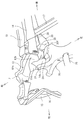
- It is a perspective view of the front part structure for expressing the operation of the front part structure.
- It is a schematic side view of the vehicle body front part structure which concerns on another structure.
- It is a schematic plan view of the front part structure of FIG.
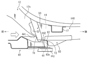
- FIG. 8 showing the function of the front part structure.
- It is a side view of the front part structure of FIG. 8 showing the function of the front part structure.
- It is a side view of the conventional vehicle body front part structure.
- FIGS. Front and rear, right and left, and up and down in the figure correspond to front and rear, left and right, and top and bottom of the vehicle.
- the vehicle body has a pair of left and right side members 10 extending in the vehicle longitudinal direction on both sides in the vehicle width direction as shown in FIG.
- the side member 10 is a skeleton part of the vehicle body, and includes a front side member 12 positioned at the front of the vehicle body (on both sides of the engine room E), and a floor side member 14 constituting the vehicle floor at the rear side of the front side member 12.
- the front side member 12 has a front side member main body 12m extending in the vehicle front-rear direction as shown in FIG. 2 and a kick portion 12k that is inclined rearward and downward from the rear side of the front side member main body 12m. Brackets 12b projecting downward are provided at the tip positions of the left and right front side members 12. A front end cross member 15 is provided between the left and right brackets 12b. A bumper reinforcement 16 is attached to the tip positions of the left and right front side members 12.
- a floor cross member 17 extending in the vehicle width direction is provided as shown in FIG. Outside the left and right floor side members 14, left and right rocker rails 19 extending in the vehicle front-rear direction are provided.
- a suspension member 20 is provided between the left and right front side members 12 as shown in FIGS.
- the suspension member 20 is disposed at a position corresponding to the kick portion 12k and is disposed substantially horizontally.
- the suspension member 20 is a plate and supports a front suspension (not shown) and an engine mount (not shown).
- the front portion of the suspension member 20 is provided with leg portions 22 protruding upward at both left and right end positions.
- the left and right leg portions 22 are connected to the bracket 12d by bolts or the like as shown in FIG.
- the bracket 12d has a trapezoidal shape and is positioned on the front side of the kick portion 12k of the front side member 12.
- flange portions 24 are provided on the left and right sides of the rear portion of the suspension member 20.
- the left and right flange portions 24 are connected to the lower surface receiving portions 14x of the left and right floor side members 14 by bolts or the like.
- the rear end portion of the reinforcing plate portion 25 is connected to the center of the front portion of the suspension member 20.
- the front end portion of the reinforcing plate portion 25 is connected to the center position of the front end cross member 15.
- the bracket 12d and the leg portion 22 correspond to the connecting position of the front side member 12 and the suspension member 20.
- the lower surface receiving portion 14 x and the flange portion 24 also correspond to the connecting position of the floor side member 12 and the suspension member 20.
- the front side member 12 is formed in a cylindrical shape having a hollow closed cross section by an inner panel 121 and an outer panel 122 as shown in FIGS.
- the inner panel 121 and the outer panel 122 have a substantially U-shaped cross section and are aligned with each other.
- a reinforcement reinforcement 123 having a substantially U-shaped cross section is superimposed on the inner surface of the inner panel 121.
- the front side member 12 has the weak part Z in the approximate center position in the length direction of the front side member main body 12m as shown in FIG.
- the fragile portion Z is configured to bend when a collision load at the time of a vehicle front collision is applied to the front side member main body 12m in the axial direction.
- the fragile portion Z has through-holes 121 h formed above and below the inner panel 121.
- the fragile portion Z includes a portion of the reinforcement 123 that is narrower than the other portions. The fragile portion Z promotes the front side member main body portion 12m to be bent so as to protrude outward in the vehicle width direction.
- the stopper member 30 is provided to stop the suspension member 20 from retreating when the vehicle collides forward as shown in FIG.
- the stopper member 30 is located on the rear side of the suspension member 20 and is provided in a range surrounded by the suspension member 20, the left and right floor side members 14, and the front floor cross member 17.
- the stopper member 30 has a substantially square hollow box shape as shown in FIG.
- the stopper member 30 has a front lower side 30 f that can receive the suspension member 20.
- the stopper member 30 is positioned such that a certain gap S is provided between the front lower side 30f and the rear end position of the suspension member 20.
- a side flange portion 33 is provided on the side surface of the stopper member 30.
- the stopper member 30 is fixed to the side surface of the floor side member 14 by the side flange portion 33.
- An upper surface flange portion 34 is provided on the upper surface of the stopper member 30.
- the stopper member 30 is fixed to the lower surface of the floor board (not shown) by the upper surface flange portion 34.
- FIG. 1 when a collision load is applied to the right front portion of the vehicle due to an offset collision or the like, a collision load (see a white arrow) is applied in the axial direction to the tip of the right front side member 12 via the bumper reinforcement 16.
- the front side member main body 12m bends outward in the vehicle width direction at the position of the fragile portion Z due to the collision load (see the two-dot chain line in FIG. 1, see FIG. 7). Thereby, a part of collision load is absorbed.
- the collision load that has passed through the fragile portion Z is distributed to the right leg portion 22 of the suspension member 20 via the kick portion 12k and the bracket 12d. A part of the collision load applied to the kick part 12k is absorbed by the deformation of the kick part 12k.
- the remaining collision load is applied to the floor side member 14 and the like (vehicle floor).
- the collision load applied to the right leg 22 of the suspension member 20 moves the suspension member 20 rearward while deforming the suspension member 20 (see the two-dot chain line in FIG. 1).
- the right rear end of the suspension member 20 contacts the front lower side 30 f of the stopper member 30. That is, the suspension member 20 is pressed later by the stopper member 30, and the stopper member 30 is deformed as shown in FIG.
- Part of the collision load is absorbed by the deformation (movement) of the suspension member 20 and the deformation of the stopper member 30.
- the collision load that has passed through the stopper member 30 is applied to the floor side member 14, the floor cross member 17 and the like (vehicle floor).
- the vehicle body front structure includes the front side member 14, the floor side member 12, the suspension member 20, and the stopper member 30, as shown in FIGS.
- the front side member 14 includes kick portions 12k that extend in the vehicle front-rear direction on both sides in the width direction of the front portion of the vehicle and are inclined rearward and downward at the rear portion.
- the floor side member 14 is connected to the rear end of the kick portion 12k and extends in the vehicle front-rear direction on both sides in the width direction of the vehicle floor.
- the suspension member 20 has front both sides connected to the left and right front side members 12 on the front side from the kick portion 12k, and rear both sides connected to the left and right floor side members 14, and supports the front suspension.
- the stopper member 30 is fixed to the vehicle floor on the rear side of the suspension member 20 and forms a gap S between the suspension member 20 and the suspension member 20 abuts when the suspension member 20 is retracted.
- the axial collision load applied to the front side member 12 at the time of a vehicle front collision is transmitted to the floor side member 14 via the kick portion 12k.
- the collision load is applied to the suspension member 20 from both front side portions of the kick portion 12k via the connecting portions 12d and 22.
- the suspension member 20 moves backward and comes into contact with the stopper member 30, and the collision load is transmitted to the vehicle floor. Therefore, the collision load is dispersed and the collision load is not concentrated on the kick portion 12k. Thus, the collision load applied to the kick portion 12k is reduced.
- the deformation amount of the kick portion 12k at the time of a vehicle front collision can be suppressed without reinforcing the kick portion 12k.
- the structure in which the stopper member 30 is disposed on the rear side of the suspension member 20 is simple and economical. Since the gap S is provided between the suspension member 20 and the stopper member 30, it is possible to suppress the vibration of the suspension member 20 from being transmitted from the stopper member 30 to the vehicle floor.
- the front side member 12 has a fragile portion Z that promotes bending in the width direction on the front side of the connection positions 12d and 22 of the front side member 12 and the suspension member 20 as shown in FIGS. Therefore, the fragile portion Z of the front side member 12 bends in the width direction (lateral direction) at the time of a vehicle front collision, and part of the collision load is absorbed by the fragile portion Z. Thereby, the collision load applied to the kick portion 12k of the front side member 12 is reduced, and deformation of the kick portion 12k can be suppressed.
- the stopper member 30 has a box shape having a hollow portion as shown in FIGS. Accordingly, a part of the collision load transmitted from the suspension member 20 to the stopper member 30 can be absorbed by the stopper member 30.
- the fragile portion Z may have a plurality of through holes 121h as shown in FIG. 6, or may have a fold line extending in the vertical direction instead of the through holes 121h.
- the stopper member 30 may have a box shape as shown in FIG. 2, or may have a partition member that partitions the internal space of the stopper member 30 so that the strength of the stopper member 30 can be adjusted.
- the vehicle body front structure may be configured as shown in FIGS.
- the vehicle body front structure shown in FIGS. 8 to 11 has a structure in which a part of the floor side member 14, suspension member 20 and stopper member 30 shown in FIGS.
- the other structure is formed similarly to the vehicle body front part structure shown in FIGS.
- the floor side member shown in FIG. 9 includes an outer floor side member 14 provided continuously with the front side member 12 and an inner floor side member 140 disposed on the inner side in the vehicle width direction of the outer floor side member 14.
- a floor cross member 17 extends in the vehicle width direction between the left and right inner floor side members 140.
- a bush 43 is connected to the lower side of the tip of the inner floor side member 140 by a bolt 41.
- the bushes 43 are provided on both the left and right sides of the rear portion of the suspension member 40.
- the bush 43 includes an outer cylinder 43e, an inner cylinder (not shown), and an anti-vibration rubber disposed between the inner cylinder and the outer cylinder 43e.
- the bush 43 is vertically fixed to the rear portion of the suspension member 40, and a bolt 41 is passed through the inner cylinder of the bush 43.
- a support surface 44 is formed at the rear portion of the suspension member 40, and the support surface 44 is higher than the fixed surface of the bush 43.
- a trapezoidal protrusion 44 t is formed on the upper surface of the rear portion of the support surface 44.
- the protrusion 44 t is located on the front side of the bush 43 and is higher than the bush 43.
- a front stopper 50 constituting a stopper member is attached to the tip of the inner floor side member 140.
- a rear stopper 60 constituting a stopper member is attached to the lower surface 142 of the inner floor side member 140. The rear stopper 60 is located behind the position where the bush 43 of the suspension member 40 is connected.
- the front stopper 50 comes into contact with the protrusion 44t when the suspension member 40 is retracted due to a vehicle front collision.
- the front stopper 50 has a lid shape that covers the tip of the inner floor side member 140.
- the front stopper 50 has a front surface 52 against which the protrusion 44t of the suspension member 40 abuts.
- the lower end of the front stopper 50 is positioned so as to have the same height as the lower surface 142 of the inner floor side member 140.
- the rear stopper 60 is a box shape formed in an inverted trapezoidal shape, and has a front surface 62 with which the outer cylinder 43e abuts.
- the rear stopper 60 is fixed to the lower surface 142 of the inner floor side member 140 and protrudes downward from the lower surface 142.
- the front-rear distance D1 (see FIG. 10) between the projection 44t and the front surface 52 of the front stopper 50 is substantially equal to the front-rear distance D2 between the outer cylinder 43e of the bush 43 and the front surface 62 of the rear stopper 60. .
- the bush 43 is attached to the inner floor side member 140 and the bracket 14z by the bolt 41 between the lower surface 142 of the inner floor side member 140 and the plate-like bracket 14z.
- the other end side of the bracket 14z is fixed to the lower surface (not shown) of the outer floor side member 14 with a bolt or the like. Therefore, the suspension member 40 and the inner floor side member 140 are connected by the bush 43 and the bolt 41 (connection position).
- the suspension member 40 moves backward while deforming due to a vehicle front collision. Accordingly, the protrusion (front protrusion) 44t of the suspension member 40 abuts on T1 of the front surface 52 of the front stopper 50. Almost simultaneously, the outer cylinder (rear protrusion) 43e of the bush 43 abuts on T2 of the front surface 62 of the rear stopper 60.
- the suspension member 40 has a protrusion 44t (front) positioned on the front side of the connection position (the position of the bolt 41) between the suspension member 40 and the inner floor side member (floor side member) 140, as shown in FIGS. And an outer cylinder 43e (rear protrusion) of the bush 43 located on the rear side of the connection position.
- the stopper member has a front stopper 50 against which the protrusion 44t abuts when the suspension member 40 is retracted, and a rear stopper 60 against which the outer cylinder 43e abuts when the suspension member 40 is retracted.
- the suspension member 40 moves backward due to a vehicle front collision, the suspension member 40 comes into contact with the front stopper 50 and the rear stopper 60 before and after the connection position with the inner floor side member 140 (position of the bolt 41). Therefore, the collision load applied to the connecting portion (bolt 41) between the suspension member 40 and the inner floor side member 140 is reduced. Thereby, it can be suppressed that the suspension member 40 and the inner floor side member 140 are disconnected. Further, the collision load can be reliably transmitted from the suspension member 40 to the vehicle floor.
- the protrusion 44t front protrusion
- the front stopper 50 is disposed at a position higher than the rear stopper 60. Accordingly, the collision between the protrusion 44t and the front stopper 50 and the collision between the outer cylinder 43e and the rear stopper are unlikely to interfere with each other.
- the floor side member 14 shown in FIG. 1 may have the outer floor side member (14) and the inner floor side member (140) shown in FIG.
- the front structure may have an outer cylinder 43e of the bush 43 as a rear protrusion, or the rear end of the suspension member 40 as a rear protrusion instead of the outer cylinder 43e, or the like. You may have the protrusion etc. which were provided in the rear-end part of the suspension member 40.
- FIG. 9 the front structure may have an outer cylinder 43e of the bush 43 as a rear protrusion, or the rear end of the suspension member 40 as a rear protrusion instead of the outer cylinder 43e, or the like. You may have the protrusion etc. which were provided in the rear-end part of the suspension member 40.
Landscapes
- Engineering & Computer Science (AREA)
- Chemical & Material Sciences (AREA)
- Combustion & Propulsion (AREA)
- Transportation (AREA)
- Mechanical Engineering (AREA)
- Body Structure For Vehicles (AREA)
Abstract
車体前部構造は、フロントサイドメンバ(12)とフロアサイドメンバ(14)とサスペンションメンバ(20)とストッパ部材(30)を有する。フロントサイドメンバ(12)は、車両前部の幅方向両側で車両前後方向に延び、かつ後部において後方にかつ下方に傾斜するキック部(12k)を備える。フロアサイドメンバ(14)は、キック部(12k)の後端に接続され、かつ車両フロアの幅方向両側で車両前後方向に延びる。サスペンションメンバ(20)は、キック部(12k)より前側にて左右のフロントサイドメンバ(12)に連結される前両側部と左右のフロアサイドメンバ(14)に連結される後両側部を有しかつフロントサスペンションを支持する。ストッパ部材(30)は、サスペンションメンバ(20)の後側にて車両フロアに固定され、サスペンションメンバ(20)との間に隙間(S)を形成し、サスペンションメンバ(20)が後退した時にサスペンションメンバ(20)が当接される。
Description
本発明は、キック部を備えるフロントサイドメンバと、フロントサイドメンバのキック部後端に接続されるフロアサイドメンバと、フロントサスペンションを支持するサスペンションメンバを有する車体前部構造に関する。
特開2004-243785号に記載の車体は、図12に示すようにエンジンルーム(図示省略)の両側に車両前後方向に延びるフロントサイドメンバ103を有する。フロントサイドメンバ103は、ほぼ水平なフロントサイドメンバ本体部103mと、エンジンルームの後端位置から後方にかつ低い方向へ緩やかに湾曲するキック部103kを有する。フロントサイドメンバ103のキック部103kの後端に車両フロアの幅方向両側で車両前後方向に延びるフロアサイドメンバ101が接続される。車両が前方衝突した場合、衝突荷重がフロントサイドメンバ103の軸方向に加わり、主としてフロントサイドメンバ103のキック部103kが縦に曲がるように変形する。これにより衝突荷重が吸収される。
最近、車室の利用性を向上させるために車両の床を従来構造より低くする。そのためフロントサイドメンバ本体部103mとフロアサイドメンバ101の高低差、即ち、フロントサイドメンバ103のキック部103kの高さ寸法が大きくなる。これにより車両が前方衝突した際の衝突荷重に対するキック部103kの強度が低下する。その結果、キック部103kの変形量が大きくなり、車室へのフロントサイドメンバ103の侵入量が増加し得る。
これを防止する1つの方法としてフロントサイドメンバ103のキック部103kを補強することが考えられる。しかしこの方法では、重量が増大しかつ経済的でない。そのため簡単な構成で車両の前方衝突時におけるフロントサイドメンバのキック部の変形量を抑え得る車体が必要である。
本発明の1つの特徴によると、車体前部構造は、フロントサイドメンバとフロアサイドメンバとサスペンションメンバとストッパ部材を有する。フロントサイドメンバは、車両前部の幅方向両側で車両前後方向に延び、かつ後部において後方にかつ下方に傾斜するキック部を備える。フロアサイドメンバは、キック部の後端に接続され、かつ車両フロアの幅方向両側で車両前後方向に延びる。サスペンションメンバは、キック部より前側にて左右のフロントサイドメンバに連結される前両側部と左右のフロアサイドメンバに連結される後両側部を有しかつフロントサスペンションを支持する。ストッパ部材は、サスペンションメンバの後側にて車両フロアに固定され、サスペンションメンバとの間に隙間を形成し、サスペンションメンバが後退した時にサスペンションメンバが当接される。
したがって車両が前方衝突した時にフロントサイドメンバに加わる軸方向の衝突荷重は、キック部を介してフロアサイドメンバに伝わる。衝突荷重は、フロントサイドメンバのキック部の前両側部から連結部分を介してサスペンションメンバに加わる。サスペンションメンバが後退してストッパ部材に当接し、衝突荷重が車両フロアに伝わる。したがって衝突荷重が分散され、衝突荷重がフロントサイドメンバのキック部に集中しなくなる。かくしてキック部に加わる衝突荷重が減少する。
したがって低床化等によりキック部の高さ寸法が大きくなった場合でも、キック部を補強することなく、車両前方衝突時におけるキック部の変形量を抑え得る。またサスペンションメンバの後側にストッパ部材を配置する構造は、簡単で経済的である。さらにサスペンションメンバとストッパ部材の間には隙間が設けられるため、サスペンションメンバの振動がストッパ部材から車両フロアに伝わることが抑制され得る。
本発明の1つの実施の形態を図1~7にしたがって説明する。図中の前後左右、及び上下は、車両の前後左右、及び上下に対応する。
車体は、図1に示すように車幅方向両側において車両前後方向に延びる左右一対のサイドメンバ10を有する。サイドメンバ10は、車体の骨格部分であり、車体の前部(エンジンルームEの両側)に位置するフロントサイドメンバ12と、フロントサイドメンバ12の後側で車両フロアを構成するフロアサイドメンバ14を備える。
フロントサイドメンバ12は、図2に示すように車両前後方向に延びるフロントサイドメンバ本体部12mと、フロントサイドメンバ本体部12mの後側から後方にかつ低い方向へ傾斜するキック部12kを有する。左右のフロントサイドメンバ12の先端位置には、下方に突出するブラケット12bが設けられる。左右のブラケット12b間には、前端部クロスメンバ15が設けられる。左右のフロントサイドメンバ12の先端位置には、バンパリインフォース16が取付けられる。
左右のフロアサイドメンバ14間には、図1に示すように車幅方向に延びるフロアクロスメンバ17が設けられる。左右のフロアサイドメンバ14の外側には、車両前後方向に延びる左右のロッカレール19が設けられる。
左右のフロントサイドメンバ12間には、図1,2に示すようにサスペンションメンバ20が設けられる。サスペンションメンバ20は、キック部12kに対応する位置に配設され、ほぼ水平に配置される。サスペンションメンバ20は、プレートであって、フロントサスペンション(図示省略)とエンジンマウント(図示省略)を支持する。サスペンションメンバ20の前部には、左右両端位置に上方に突出する脚部22が設けられる。
左右の脚部22は、図2に示すようにブラケット12dにボルト等により連結される。ブラケット12dは、台形状であってフロントサイドメンバ12のキック部12kよりも前側に位置する。サスペンションメンバ20の後部の左右両側には、図1に示すようにフランジ部24が設けられる。左右のフランジ部24は、左右のフロアサイドメンバ14の下面受け部14xにボルト等により連結される。
サスペンションメンバ20の前部中央には、図1に示すように補強板部25の後端部が連結される。補強板部25の前端部は、前端部クロスメンバ15の中央位置に連結される。ブラケット12dと脚部22は、フロントサイドメンバ12とサスペンションメンバ20の連結位置に相当する。下面受け部14xとフランジ部24も、フロアサイドメンバ12とサスペンションメンバ20の連結位置に相当する。
フロントサイドメンバ12は、図5,6に示すようにインナパネル121とアウタパネル122によって中空閉断面の筒状に形成される。インナパネル121とアウタパネル122は、断面略横向きU字形を有し、互いに合わせられる。断面略横向きU字形をした補強用のリインフォースメント123がインナパネル121に内側面に重ねられる。
フロントサイドメンバ12は、図4に示すようにフロントサイドメンバ本体部12mの長さ方向における略中央位置に脆弱部Zを有する。脆弱部Zは、車両前方衝突時の衝突荷重がフロントサイドメンバ本体部12mに対して軸方向に加わったときに折れ曲がるように構成される。脆弱部Zは、図6に示すようにインナパネル121の上下に形成された貫通孔121hを有する。脆弱部Zは、他の部分よりも幅の狭いリインフォースメント123の一部分を含む。脆弱部Zは、フロントサイドメンバ本体部12mが車幅方向外側に突出するように折れ曲がることを促進する。
ストッパ部材30は、図1に示すように車両前方衝突時にサスペンションメンバ20の後退を止めるために設けられる。ストッパ部材30は、サスペンションメンバ20の後側に位置し、サスペンションメンバ20と左右のフロアサイドメンバ14と前側のフロアクロスメンバ17に囲まれる範囲に設けられる。
ストッパ部材30は、図2に示すように略角形の中空箱状である。ストッパ部材30は、サスペンションメンバ20を受け得る前面下側30fを有する。前面下側30fとサスペンションメンバ20の後端位置の間に一定の隙間Sが設けられるようにストッパ部材30が位置決めされる。
図2に示すようにストッパ部材30の側面に側面フランジ部33が設けられる。ストッパ部材30は、側面フランジ部33によってフロアサイドメンバ14の側面に固定される。ストッパ部材30の上面に上面フランジ部34が設けられる。ストッパ部材30は、上面フランジ部34によって床板(図示省略)の下面に固定される。
前方衝突時における車体前部構造の動作を以下に説明する。図1に示すようにオフセット衝突等により車両右前部に衝突荷重が加わった際、バンパリインフォース16を介して右側のフロントサイドメンバ12の先端に衝突荷重(白矢印参照)が軸方向に加わる。衝突荷重によりフロントサイドメンバ本体部12mが脆弱部Zの位置で車幅方向外側に折れ曲がる(図1の二点鎖線参照、図7参照)。これにより衝突荷重の一部が吸収される。脆弱部Zを通過した衝突荷重は、キック部12kとブラケット12dを介してサスペンションメンバ20の右脚部22に分散される。キック部12kに加わった衝突荷重の一部は、キック部12kの変形により吸収される。残りの衝突荷重は、フロアサイドメンバ14等(車両フロア)に加わる。
サスペンションメンバ20の右脚部22に加わった衝突荷重は、サスペンションメンバ20を変形させつつ後方に移動させる(図1二点鎖線参照)。これによりサスペンションメンバ20の右後端がストッパ部材30の前面下側30fに当接する。即ち、サスペンションメンバ20がストッパ部材30によって後から押えられ、図7に示すようにストッパ部材30が変形する。サスペンションメンバ20の変形(移動)とストッパ部材30の変形により衝突荷重の一部が吸収される。ストッパ部材30を通過した衝突荷重は、フロアサイドメンバ14、フロアクロスメンバ17等(車両フロア)に加わる。
以上のように車体前部構造は、図1,2に示すようにフロントサイドメンバ14とフロアサイドメンバ12とサスペンションメンバ20とストッパ部材30を有する。フロントサイドメンバ14は、車両前部の幅方向両側で車両前後方向に延び、かつ後部において後方にかつ下方に傾斜するキック部12kを備える。フロアサイドメンバ14は、キック部12kの後端に接続され、かつ車両フロアの幅方向両側で車両前後方向に延びる。サスペンションメンバ20は、キック部12kより前側にて左右のフロントサイドメンバ12に連結される前両側部と左右のフロアサイドメンバ14に連結される後両側部を有しかつフロントサスペンションを支持する。ストッパ部材30は、サスペンションメンバ20の後側にて車両フロアに固定され、サスペンションメンバ20との間に隙間Sを形成し、サスペンションメンバ20が後退した時にサスペンションメンバ20が当接される。
したがって車両前方衝突時にフロントサイドメンバ12に加わる軸方向の衝突荷重は、キック部12kを介してフロアサイドメンバ14に伝わる。衝突荷重は、キック部12kの前両側部から連結部分12d,22を介してサスペンションメンバ20に加わる。サスペンションメンバ20が後退してストッパ部材30に当接し、衝突荷重が車両フロアに伝わる。したがって衝突荷重が分散され、衝突荷重がキック部12kに集中しなくなる。かくしてキック部12kに加わる衝突荷重が減少する。
したがって低床化等によりキック部12kの高さ寸法が大きくなった場合でも、キック部12kを補強することなく、車両前方衝突時におけるキック部12kの変形量を抑え得る。サスペンションメンバ20の後側にストッパ部材30を配置する構造は、簡単で経済的である。サスペンションメンバ20とストッパ部材30の間には隙間Sが設けられるため、サスペンションメンバ20の振動がストッパ部材30から車両フロアに伝わることが抑制され得る。
フロントサイドメンバ12は、図1,2に示すようにフロントサイドメンバ12とサスペンションメンバ20の連結位置12d,22よりも前側にて幅方向に曲がることを促進する脆弱部Zを有する。したがって車両前方衝突時にフロントサイドメンバ12の脆弱部Zが幅方向(横方向)に曲がり、衝突荷重の一部が脆弱部Zで吸収される。これによりフロントサイドメンバ12のキック部12kに加わる衝突荷重が減少し、キック部12kの変形が抑制され得る。
ストッパ部材30は、図1,2に示すように中空部を有する箱状である。したがってサスペンションメンバ20からストッパ部材30に伝わる衝突荷重の一部は、ストッパ部材30によって吸収され得る。
本発明の形態を上記構造を参照して説明したが、本発明の目的を逸脱せずに多くの交代、改良、変更が可能であることは当業者であれば明らかである。したがって本発明の形態は、添付された請求項の精神と目的を逸脱しない全ての交代、改良、変更を含み得る。例えば本発明の形態は、前記特別な構造に限定されず、下記のように変更が可能である。
脆弱部Zは、図6に示すように複数の貫通孔121hを有していても良いし、貫通孔121hの代わりに縦方向に延びる折線を有していても良い。
ストッパ部材30は、図2に示すように箱状でも良いし、ストッパ部材30の強度を調整し得るようにストッパ部材30の内部空間を仕切る仕切部材を有していても良い。
車体前部構造は、図8~11に示すように構成されても良い。図8~11に示す車体前部構造は、図1,2に示すフロアサイドメンバ14、サスペンションメンバ20及びストッパ部材30の一部を改良した構造を有する。他の構成は、図1,2に示す車体前部構造と同様に形成される。
図9に示すフロアサイドメンバは、フロントサイドメンバ12に連続して設けられた外側フロアサイドメンバ14と、外側フロアサイドメンバ14の車幅方向内側に配置される内側フロアサイドメンバ140を備える。左右の内側フロアサイドメンバ140間にてフロアクロスメンバ17が車幅方向に延びる。
図8,9に示すように内側フロアサイドメンバ140の先端部下側には、ブッシュ43がボルト41により連結される。ブッシュ43は、サスペンションメンバ40の後部の左右両側に設けられる。ブッシュ43は、外筒43e、内筒(図示省略)、内筒と外筒43e間に配設される防振ゴムを備える。ブッシュ43は、サスペンションメンバ40の後部に縦向きで固定され、ブッシュ43の内筒にボルト41が通される。
図8に示すようにサスペンションメンバ40の後部には支持面44が形成され、支持面44は、ブッシュ43の固定面よりも位置が高い。支持面44の後部上面に台形状の突起部44tが形成される。突起部44tは、ブッシュ43よりも前側に位置し、ブッシュ43よりも位置が高い。
図8に示すように内側フロアサイドメンバ140の先端部には、ストッパ部材を構成する前部ストッパ50が取付けられる。内側フロアサイドメンバ140の下面142には、ストッパ部材を構成する後部ストッパ60が取付けられる。後部ストッパ60は、サスペンションメンバ40のブッシュ43が連結される位置よりも後方に位置する。
図8に示すように前部ストッパ50は、車両前方衝突によりサスペンションメンバ40が後退したときに、突起部44tに当接する。前部ストッパ50は、内側フロアサイドメンバ140の先端を覆おう蓋形状を有する。前部ストッパ50は、サスペンションンメンバ40の突起部44tが当接する前面52を有する。前部ストッパ50の下端は、内側フロアサイドメンバ140の下面142と等しい高さになるように位置決めされる。
図8に示すように後部ストッパ60は、サスペンションメンバ40が後退したときに、ブッシュ43の外筒43eが当接する。後部ストッパ60は、逆台形状に形成された箱型であり、外筒43eが当接する前面62を有する。後部ストッパ60は、内側フロアサイドメンバ140の下面142に固定され、下面142から下方に突出する。
図10に示すように突起部44tと前部ストッパ50の前面52間の前後距離D1(図10参照)は、ブッシュ43の外筒43eと後部ストッパ60の前面62間の前後距離D2とほぼ等しい。
図8に示すようにブッシュ43は、内側フロアサイドメンバ140の下面142と、板状のブラケット14zの間においてボルト41によって内側フロアサイドメンバ140とブラケット14zに取付けられる。ブラケット14zの他端側は、外側フロアサイドメンバ14の下面(図示省略)にボルト等により固定される。したがってブッシュ43とボルト41によってサスペンションメンバ40と内側フロアサイドメンバ140が連結される(連結位置)。
図10,11に示すように車両前方衝突によりサスペンションメンバ40が変形しつつ後退する。これによりサスペンションメンバ40の突起部(前寄り突部)44tが前部ストッパ50の前面52のT1に当接する。ほぼ同時に、ブッシュ43の外筒(後側突部)43eが後部ストッパ60の前面62のT2に当接する。
以上のようにサスペンションメンバ40は、図10,11に示すようにサスペンションメンバ40と内側フロアサイドメンバ(フロアサイドメンバ)140の連結位置(ボルト41の位置)より前側に位置する突起部44t(前寄り突起)と、連結位置より後側に位置するブッシュ43の外筒43e(後側突部)を有する。ストッパ部材は、サスペンションメンバ40の後退時に突起部44tが当接される前部ストッパ50と、前記後退時に外筒43eが当接される後部ストッパ60を有する。
したがって車両前方衝突によってサスペンションメンバ40が後退したとき、サスペンションメンバ40が内側フロアサイドメンバ140との連結位置(ボルト41の位置)の前後で前部ストッパ50と後部ストッパ60に当接する。そのためサスペンションメンバ40と内側フロアサイドメンバ140の連結部位(ボルト41)に加わる衝突荷重が減少する。これによりサスペンションメンバ40と内側フロアサイドメンバ140の連結が外れることが抑制され得る。また衝突荷重を確実にサスペンションメンバ40から車両フロアに伝達し得る。
図10に示すように突起部44t(前寄り突起)は、ブッシュ43の外筒43e(後側突部)よりも高い位置に配置される。前部ストッパ50は、後部ストッパ60よりも高い位置に配置される。したがって突起部44tと前部ストッパ50の衝突、及び外筒43eと後部ストッパの衝突は、互いに干渉し難い。
図9に示すフロアサイドメンバと同様に、図1に示すフロアサイドメンバ14が図9に示す外側フロアサイドメンバ(14)と内側フロアサイドメンバ(140)を有していても良い。
前部構造は、図9に示すように後側突起としてブッシュ43の外筒43eを有していても良いし、外筒43eの代わりに後側突起としてサスペンションメンバ40の後端部等、あるいはサスペンションメンバ40の後端部に設けられた突起等を有していても良い。
Claims (5)
- 車体前部構造であって、
車両前部の幅方向両側で車両前後方向に延び、かつ後部において後方にかつ下方に傾斜するキック部を備えるフロントサイドメンバと、
前記キック部の後端に接続され、かつ車両フロアの幅方向両側で車両前後方向に延びるフロアサイドメンバと、
前記キック部より前側にて左右の前記フロントサイドメンバに連結される前両側部と左右の前記フロアサイドメンバに連結される後両側部を有しかつフロントサスペンションを支持するサスペンションメンバと、
前記サスペンションメンバの後側にて前記車両フロアに固定され、前記サスペンションメンバとの間に隙間を形成し、前記サスペンションメンバが後退した時に前記サスペンションメンバが当接されるストッパ部材を有する車体前部構造。 - 請求項1に記載の車体前部構造であって、
前記フロントサイドメンバは、前記フロントサイドメンバと前記サスペンションメンバの連結位置よりも前側にて幅方向に曲がることを促進する脆弱部を有する車体前部構造。 - 請求項1または2に記載の車体前部構造であって、
前記ストッパ部材は、中空部を有する箱状である車体前部構造。 - 請求項1から3のいずれか1つに記載の車体前部構造であって、
前記サスペンションメンバは、前記サスペンションメンバと前記フロアサイドメンバの連結位置より前側に位置する前寄り突部と、前記連結位置より後側に位置する後側突部を有し、
前記ストッパ部材は、前記サスペンションメンバの前記後退時に前記前寄り突部が当接される前部ストッパと、前記後退時に前記後側突部が当接される後部ストッパを有する車体前部構造。 - 請求項4に記載の車体前部構造であって、
前記前寄り突部は、前記後側突部よりも高い位置に配置され、
前記前部ストッパは、前記後部ストッパよりも高い位置に配置される車体前部構造。
Applications Claiming Priority (4)
| Application Number | Priority Date | Filing Date | Title |
|---|---|---|---|
| JP2011-067380 | 2011-03-25 | ||
| JP2011067380 | 2011-03-25 | ||
| JP2012-011049 | 2012-01-23 | ||
| JP2012011049A JP5880071B2 (ja) | 2011-03-25 | 2012-01-23 | 車両の車体前部構造 |
Publications (1)
| Publication Number | Publication Date |
|---|---|
| WO2012133101A1 true WO2012133101A1 (ja) | 2012-10-04 |
Family
ID=46930829
Family Applications (1)
| Application Number | Title | Priority Date | Filing Date |
|---|---|---|---|
| PCT/JP2012/057323 Ceased WO2012133101A1 (ja) | 2011-03-25 | 2012-03-22 | 車体前部構造 |
Country Status (2)
| Country | Link |
|---|---|
| JP (1) | JP5880071B2 (ja) |
| WO (1) | WO2012133101A1 (ja) |
Cited By (4)
| Publication number | Priority date | Publication date | Assignee | Title |
|---|---|---|---|---|
| CN105246769A (zh) * | 2013-05-27 | 2016-01-13 | 丰田自动车株式会社 | 车身前部结构 |
| US20190118863A1 (en) * | 2016-01-28 | 2019-04-25 | Honda Motor Co., Ltd. | Vehicle body front structure and impact absorbing method of vehicle body front structure |
| JP2020006730A (ja) * | 2018-07-03 | 2020-01-16 | トヨタ自動車株式会社 | 車両前部構造 |
| CN115416470A (zh) * | 2018-07-03 | 2022-12-02 | 丰田自动车株式会社 | 车辆前部结构 |
Families Citing this family (8)
| Publication number | Priority date | Publication date | Assignee | Title |
|---|---|---|---|---|
| JP2014201282A (ja) * | 2013-04-09 | 2014-10-27 | トヨタ自動車株式会社 | 車両前部構造 |
| JP5945762B2 (ja) * | 2013-06-17 | 2016-07-05 | トヨタ自動車東日本株式会社 | 車両前部構造 |
| JP6468430B2 (ja) * | 2015-03-25 | 2019-02-13 | 三菱自動車工業株式会社 | 車体前部構造 |
| JP2019137271A (ja) * | 2018-02-13 | 2019-08-22 | トヨタ自動車株式会社 | 車両前部構造 |
| JP6787372B2 (ja) * | 2018-07-13 | 2020-11-18 | トヨタ自動車株式会社 | 車両の下部構造 |
| JP6787373B2 (ja) * | 2018-07-13 | 2020-11-18 | トヨタ自動車株式会社 | 車両の下部構造 |
| JP6787371B2 (ja) * | 2018-07-13 | 2020-11-18 | トヨタ自動車株式会社 | 車両の下部構造 |
| JP6937083B2 (ja) * | 2018-10-29 | 2021-09-22 | ダイハツ工業株式会社 | 車両構造 |
Citations (6)
| Publication number | Priority date | Publication date | Assignee | Title |
|---|---|---|---|---|
| JPH08282534A (ja) * | 1995-04-18 | 1996-10-29 | Nissan Motor Co Ltd | 車体サブフレームのエクステンションメンバへの取付け構造 |
| JP2001030949A (ja) * | 1999-07-26 | 2001-02-06 | Mazda Motor Corp | 車両の前部車体構造 |
| JP2002240739A (ja) * | 2001-02-14 | 2002-08-28 | Nissan Motor Co Ltd | 車体前部構造 |
| JP2004237969A (ja) * | 2002-12-12 | 2004-08-26 | Nissan Motor Co Ltd | 車体前部構造 |
| JP2004284427A (ja) * | 2003-03-20 | 2004-10-14 | Toyota Motor Corp | サスペンションメンバ取付構造 |
| JP2005271811A (ja) * | 2004-03-25 | 2005-10-06 | Mazda Motor Corp | 車体の前部構造 |
-
2012
- 2012-01-23 JP JP2012011049A patent/JP5880071B2/ja not_active Expired - Fee Related
- 2012-03-22 WO PCT/JP2012/057323 patent/WO2012133101A1/ja not_active Ceased
Patent Citations (6)
| Publication number | Priority date | Publication date | Assignee | Title |
|---|---|---|---|---|
| JPH08282534A (ja) * | 1995-04-18 | 1996-10-29 | Nissan Motor Co Ltd | 車体サブフレームのエクステンションメンバへの取付け構造 |
| JP2001030949A (ja) * | 1999-07-26 | 2001-02-06 | Mazda Motor Corp | 車両の前部車体構造 |
| JP2002240739A (ja) * | 2001-02-14 | 2002-08-28 | Nissan Motor Co Ltd | 車体前部構造 |
| JP2004237969A (ja) * | 2002-12-12 | 2004-08-26 | Nissan Motor Co Ltd | 車体前部構造 |
| JP2004284427A (ja) * | 2003-03-20 | 2004-10-14 | Toyota Motor Corp | サスペンションメンバ取付構造 |
| JP2005271811A (ja) * | 2004-03-25 | 2005-10-06 | Mazda Motor Corp | 車体の前部構造 |
Cited By (12)
| Publication number | Priority date | Publication date | Assignee | Title |
|---|---|---|---|---|
| CN105246769A (zh) * | 2013-05-27 | 2016-01-13 | 丰田自动车株式会社 | 车身前部结构 |
| EP3006311A4 (en) * | 2013-05-27 | 2016-06-01 | Toyota Motor Co Ltd | Structure for front part of vehicle body |
| US20190118863A1 (en) * | 2016-01-28 | 2019-04-25 | Honda Motor Co., Ltd. | Vehicle body front structure and impact absorbing method of vehicle body front structure |
| US10717468B2 (en) * | 2016-01-28 | 2020-07-21 | Honda Motor Co., Ltd. | Vehicle body front structure and impact absorbing method of vehicle body front structure |
| JP2020006730A (ja) * | 2018-07-03 | 2020-01-16 | トヨタ自動車株式会社 | 車両前部構造 |
| JP2022168284A (ja) * | 2018-07-03 | 2022-11-04 | トヨタ自動車株式会社 | 車両前部構造 |
| CN115416470A (zh) * | 2018-07-03 | 2022-12-02 | 丰田自动车株式会社 | 车辆前部结构 |
| JP7225580B2 (ja) | 2018-07-03 | 2023-02-21 | トヨタ自動車株式会社 | 車両前部構造 |
| EP3590792B1 (en) * | 2018-07-03 | 2023-12-27 | Toyota Jidosha Kabushiki Kaisha | Vehicle front-part structure |
| EP4328056A3 (en) * | 2018-07-03 | 2024-06-05 | Toyota Jidosha Kabushiki Kaisha | Vehicle front-part structure |
| JP7571770B2 (ja) | 2018-07-03 | 2024-10-23 | トヨタ自動車株式会社 | 車両前部構造 |
| CN115416470B (zh) * | 2018-07-03 | 2025-10-17 | 丰田自动车株式会社 | 车辆前部结构 |
Also Published As
| Publication number | Publication date |
|---|---|
| JP5880071B2 (ja) | 2016-03-08 |
| JP2012214213A (ja) | 2012-11-08 |
Similar Documents
| Publication | Publication Date | Title |
|---|---|---|
| WO2012133101A1 (ja) | 車体前部構造 | |
| JP6756793B2 (ja) | 車体後部構造 | |
| JP6756792B2 (ja) | 車体後部構造 | |
| JP6982197B2 (ja) | 車体構造 | |
| US20170096169A1 (en) | Vehicle body front structure | |
| CN105984509A (zh) | 汽车车身 | |
| JP2004217108A (ja) | 自動車の車体前部構造 | |
| JP6753904B2 (ja) | 車体後部構造 | |
| JP5775382B2 (ja) | 車体前部構造 | |
| CN110949524B (zh) | 车体前部结构 | |
| JP2009286181A (ja) | 車体骨格構造 | |
| JP2020050185A (ja) | 車体前部構造 | |
| JP2004210219A (ja) | 自動車の車体前部構造 | |
| JP2020050186A (ja) | 車体前部構造 | |
| JP3687604B2 (ja) | 車体前部構造 | |
| JP2019025945A (ja) | キャブオーバー型車両の車体前部構造 | |
| JP2008195204A (ja) | 車両の車体前部構造 | |
| JP6694593B2 (ja) | キャブの底面部構造 | |
| CN204415516U (zh) | 前副车架安装结构与汽车 | |
| JP5292245B2 (ja) | 車体の前突荷重支持体 | |
| JP6590862B2 (ja) | サスペンションアーム支持構造 | |
| JP2010115946A (ja) | 車体前部構造 | |
| JP5071163B2 (ja) | 車両のサブフレーム | |
| JP6772230B2 (ja) | 車体前部構造 | |
| JP4485847B2 (ja) | 車体構造 |
Legal Events
| Date | Code | Title | Description |
|---|---|---|---|
| 121 | Ep: the epo has been informed by wipo that ep was designated in this application |
Ref document number: 12763644 Country of ref document: EP Kind code of ref document: A1 |
|
| NENP | Non-entry into the national phase |
Ref country code: DE |
|
| 122 | Ep: pct application non-entry in european phase |
Ref document number: 12763644 Country of ref document: EP Kind code of ref document: A1 |