WO2012132924A1 - Échangeur de chaleur - Google Patents
Échangeur de chaleur Download PDFInfo
- Publication number
- WO2012132924A1 WO2012132924A1 PCT/JP2012/056679 JP2012056679W WO2012132924A1 WO 2012132924 A1 WO2012132924 A1 WO 2012132924A1 JP 2012056679 W JP2012056679 W JP 2012056679W WO 2012132924 A1 WO2012132924 A1 WO 2012132924A1
- Authority
- WO
- WIPO (PCT)
- Prior art keywords
- flat
- opening
- heat exchanger
- tube
- hole
- Prior art date
Links
Images


Classifications
-
- F—MECHANICAL ENGINEERING; LIGHTING; HEATING; WEAPONS; BLASTING
- F28—HEAT EXCHANGE IN GENERAL
- F28D—HEAT-EXCHANGE APPARATUS, NOT PROVIDED FOR IN ANOTHER SUBCLASS, IN WHICH THE HEAT-EXCHANGE MEDIA DO NOT COME INTO DIRECT CONTACT
- F28D9/00—Heat-exchange apparatus having stationary plate-like or laminated conduit assemblies for both heat-exchange media, the media being in contact with different sides of a conduit wall
- F28D9/0031—Heat-exchange apparatus having stationary plate-like or laminated conduit assemblies for both heat-exchange media, the media being in contact with different sides of a conduit wall the conduits for one heat-exchange medium being formed by paired plates touching each other
- F28D9/0043—Heat-exchange apparatus having stationary plate-like or laminated conduit assemblies for both heat-exchange media, the media being in contact with different sides of a conduit wall the conduits for one heat-exchange medium being formed by paired plates touching each other the plates having openings therein for circulation of at least one heat-exchange medium from one conduit to another
-
- F—MECHANICAL ENGINEERING; LIGHTING; HEATING; WEAPONS; BLASTING
- F28—HEAT EXCHANGE IN GENERAL
- F28D—HEAT-EXCHANGE APPARATUS, NOT PROVIDED FOR IN ANOTHER SUBCLASS, IN WHICH THE HEAT-EXCHANGE MEDIA DO NOT COME INTO DIRECT CONTACT
- F28D7/00—Heat-exchange apparatus having stationary tubular conduit assemblies for both heat-exchange media, the media being in contact with different sides of a conduit wall
- F28D7/0008—Heat-exchange apparatus having stationary tubular conduit assemblies for both heat-exchange media, the media being in contact with different sides of a conduit wall the conduits for one medium being in heat conductive contact with the conduits for the other medium
- F28D7/0025—Heat-exchange apparatus having stationary tubular conduit assemblies for both heat-exchange media, the media being in contact with different sides of a conduit wall the conduits for one medium being in heat conductive contact with the conduits for the other medium the conduits for one medium or the conduits for both media being flat tubes or arrays of tubes
-
- F—MECHANICAL ENGINEERING; LIGHTING; HEATING; WEAPONS; BLASTING
- F28—HEAT EXCHANGE IN GENERAL
- F28F—DETAILS OF HEAT-EXCHANGE AND HEAT-TRANSFER APPARATUS, OF GENERAL APPLICATION
- F28F3/00—Plate-like or laminated elements; Assemblies of plate-like or laminated elements
- F28F3/02—Elements or assemblies thereof with means for increasing heat-transfer area, e.g. with fins, with recesses, with corrugations
- F28F3/04—Elements or assemblies thereof with means for increasing heat-transfer area, e.g. with fins, with recesses, with corrugations the means being integral with the element
- F28F3/042—Elements or assemblies thereof with means for increasing heat-transfer area, e.g. with fins, with recesses, with corrugations the means being integral with the element in the form of local deformations of the element
- F28F3/046—Elements or assemblies thereof with means for increasing heat-transfer area, e.g. with fins, with recesses, with corrugations the means being integral with the element in the form of local deformations of the element the deformations being linear, e.g. corrugations
-
- F—MECHANICAL ENGINEERING; LIGHTING; HEATING; WEAPONS; BLASTING
- F28—HEAT EXCHANGE IN GENERAL
- F28D—HEAT-EXCHANGE APPARATUS, NOT PROVIDED FOR IN ANOTHER SUBCLASS, IN WHICH THE HEAT-EXCHANGE MEDIA DO NOT COME INTO DIRECT CONTACT
- F28D1/00—Heat-exchange apparatus having stationary conduit assemblies for one heat-exchange medium only, the media being in contact with different sides of the conduit wall, in which the other heat-exchange medium is a large body of fluid, e.g. domestic or motor car radiators
- F28D1/02—Heat-exchange apparatus having stationary conduit assemblies for one heat-exchange medium only, the media being in contact with different sides of the conduit wall, in which the other heat-exchange medium is a large body of fluid, e.g. domestic or motor car radiators with heat-exchange conduits immersed in the body of fluid
- F28D1/04—Heat-exchange apparatus having stationary conduit assemblies for one heat-exchange medium only, the media being in contact with different sides of the conduit wall, in which the other heat-exchange medium is a large body of fluid, e.g. domestic or motor car radiators with heat-exchange conduits immersed in the body of fluid with tubular conduits
- F28D1/053—Heat-exchange apparatus having stationary conduit assemblies for one heat-exchange medium only, the media being in contact with different sides of the conduit wall, in which the other heat-exchange medium is a large body of fluid, e.g. domestic or motor car radiators with heat-exchange conduits immersed in the body of fluid with tubular conduits the conduits being straight
- F28D1/0535—Heat-exchange apparatus having stationary conduit assemblies for one heat-exchange medium only, the media being in contact with different sides of the conduit wall, in which the other heat-exchange medium is a large body of fluid, e.g. domestic or motor car radiators with heat-exchange conduits immersed in the body of fluid with tubular conduits the conduits being straight the conduits having a non-circular cross-section
-
- F—MECHANICAL ENGINEERING; LIGHTING; HEATING; WEAPONS; BLASTING
- F28—HEAT EXCHANGE IN GENERAL
- F28F—DETAILS OF HEAT-EXCHANGE AND HEAT-TRANSFER APPARATUS, OF GENERAL APPLICATION
- F28F1/00—Tubular elements; Assemblies of tubular elements
- F28F1/02—Tubular elements of cross-section which is non-circular
- F28F1/022—Tubular elements of cross-section which is non-circular with multiple channels
Definitions
- the present invention relates to a heat exchanger for causing heat exchange between a high-pressure refrigerant and a low-pressure refrigerant.
- a water heat exchanger that performs heat exchange between CO 2 and water is used.
- water heat exchangers such as a plate type heat exchanger and a double pipe type heat exchanger.
- Patent Document 1 Japanese Patent Laid-Open No. 10-288480
- Patent Document 2 Japanese Patent Laid-Open No. 2002-228370
- Japanese Patent Laid-Open No. 2002-228370 describes a double-pipe heat exchanger.
- the double-pipe heat exchanger has, for example, a structure in which a heat medium tube is wound spirally around a core tube.
- the flow path in which the heat exchange is performed is long, but in the case of a double-tube heat exchanger, the core tube If the length becomes longer, it is necessary to bend the core tube when it is installed in the apparatus. When bending the core tube, it is necessary to bend with a certain radius of curvature so that the core tube does not break. growing.
- An object of the present invention is to provide a lightweight and compact heat exchanger that supports heat exchange between a high pressure fluid and a low pressure fluid, such as heat exchange between CO 2 and water.
- a heat exchanger includes a plurality of flat tubes having first and second openings connected to a first flow path and a first flow path, and one flat tube adjacent to each other.
- a first fluid inlet / outlet portion formed by joining the first opening and the second opening of the other flat tube and a plurality of flat tubes are alternately stacked, and the second fluid is higher in pressure than the first fluid.
- a plurality of flat multi-hole tubes in which a plurality of second flow paths through which fluid flows are formed.
- the 1st opening part and 2nd opening part of flat tubes are directly joined, and an entrance / exit part is formed, Between the 1st opening part and the 2nd opening part There is no need to provide a separate member, and the heat exchanger can be made compact. Moreover, since the entrance / exit part is formed by the 1st opening part or 2nd opening part of a flat tube, weight reduction can be achieved. On the other hand, since the flat tube through which the low-pressure first fluid flows and the flat multi-hole tube through which the high-pressure second fluid flows are alternately stacked, the heat exchanger has a structure suitable for heat exchange between the high-pressure fluid and the low-pressure fluid Can be.
- a heat exchanger is the heat exchanger according to the first aspect, wherein the flat tube is formed by overlapping and joining the first plate and the second plate, and the first plate and the second plate At least one of the plates has a concave surface portion that extends to an arrangement position of the first opening and the second opening to form the first flow path.
- corrosion is generated by configuring the flow paths of the first fluid and the second fluid as separate members such as a flat tube made of the first plate and the second plate and a flat multi-hole tube. When this is done, mixing of the first fluid and the second fluid can be prevented.
- the entrance / exit part can be comprised with a 1st plate and a 2nd plate, the manufacturing cost of a heat exchanger can be suppressed.
- a heat exchanger is the heat exchanger according to the first aspect or the second aspect, wherein at least one of the plurality of flat tubes and the plurality of flat multi-hole tubes is a flat tube and a flat multi-hole.
- a concave groove having a length protruding from the contact area is formed in a contact area where the tubes come into contact with each other. According to the heat exchanger of the third aspect, this concave groove can guide the first fluid out of the contact area when a hole is opened in the flat tube. Thereby, it becomes easy to discover that a hole has opened in the flat tube.
- a heat exchanger is the heat exchanger according to any one of the first to third aspects, wherein the plurality of flat tubes generate a turbulent flow of the first fluid inside the first flow path. It has at least one of the recessed part and convex part for making it. According to the heat exchanger of the 4th viewpoint, heat transfer is accelerated
- a heat exchanger according to a fifth aspect of the present invention is the heat exchanger according to any one of the first to fourth aspects, wherein the plurality of flat multi-hole tubes are arranged two by two between each of the plurality of flat tubes. Configured. According to the heat exchanger of the fifth aspect, since two flat multi-hole tubes come into contact with one flat tube, the number of flat multi-hole tubes that exchange heat with one flat tube is increased to two. Can do.
- a heat exchanger according to a sixth aspect of the present invention is the heat exchanger according to any one of the first to fifth aspects, wherein the plurality of flat multi-hole tubes are formed straight in a top view, and the inlet / outlet portion is It is arranged beside a plurality of flat multi-hole tubes. According to the heat exchanger of the sixth aspect, it is possible to provide a heat exchanger having a structure in which an inlet / outlet portion is located beside a flat multi-hole tube.
- a heat exchanger according to a seventh aspect of the present invention is the heat exchanger according to any one of the first to fifth aspects, wherein the plurality of flat tubes are formed straight in a top view, and the plurality of flat multi-hole tubes In order to distribute the second fluid to the plurality of second flow paths, a plurality of flat multi-hole pipes are further provided, and an inlet / outlet distribution pipe disposed on the side of the flat pipe is further provided. According to the heat exchanger of the seventh aspect, it is possible to provide a heat exchanger having a structure in which an inlet / outlet distribution pipe is provided beside the flat tube.
- a heat exchanger is the heat exchanger according to any one of the first to seventh aspects, wherein the inlet / outlet portion is a partition member that blocks the flow of the first fluid in the direction in which the flat tubes are adjacent to each other. In the flat tube, the flow direction of the first fluid changes between the upper layer and the lower layer above the partition member.
- the first fluid is reciprocated using the upper layer and the lower layer by changing the flow direction of the first fluid between the upper layer and the lower layer above the partition member. The portion where heat exchange is performed between the first fluid and the second fluid can be lengthened.
- a heat exchanger is the heat exchanger according to the second aspect, wherein the first opening is formed on the right first opening and the left first formed at the right end and the left end of the first plate. 1 opening portion, the second opening portion includes a right side second opening portion and a left side second opening portion formed at the right end portion and the left end portion of the second plate, and the doorway portion includes the right side first opening portion and the right opening portion.
- a right-side entrance / exit portion formed by joining the right-side second opening and a left-side entrance / exit portion formed by joining the left-side first opening and the left-side second opening.
- the outlet and the inlet of the first fluid can be configured by a right inlet / outlet part and a left inlet / outlet part formed by joining the first opening and the second opening.
- a heat exchanger according to a tenth aspect of the present invention is the heat exchanger according to any one of the first to ninth aspects, wherein the first fluid includes water, the second fluid is carbon dioxide, and the flat tube Is made of stainless steel or copper alloy, and the flat multi-hole tube is made of aluminum.
- the flat tube can be given good thermal conductivity as well as corrosion resistance.
- a large number of flow paths can be easily formed by using aluminum which is easy to process.
- the heat exchanger according to the first aspect of the present invention provides a lightweight and compact heat exchanger that supports heat exchange between a low-pressure first fluid and a high-pressure second fluid, such as heat exchange between water and CO 2. be able to.
- a low-pressure first fluid such as heat exchange between water and CO 2.
- heat transfer is promoted by the concave portions and the convex portions, and the heat exchanger efficiency is improved.
- the number of flat multi-hole tubes that exchange heat with respect to one flat tube can be increased, so that the efficiency of heat exchange can be increased.
- the heat exchanger which concerns on the 6th viewpoint of this invention, it can respond to the case where an entrance / exit part is to be provided beside a flat multi-hole pipe. In the heat exchanger which concerns on the 7th viewpoint of this invention, it can respond to the case where it is desired to provide an inlet / outlet distribution pipe beside the flat tube.
- the heat exchange efficiency can be increased by elongating the portion where heat exchange is performed by the partition member.
- the outlet and the inlet of the first fluid can be formed by joining the first opening and the second opening, and the size and weight can be reduced.
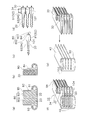
- FIG. 5 is a cross-sectional view taken along the line II of FIG.
- the top view which shows the metal plate of the one structural member of a heat exchanger. II-II sectional view taken on the line of FIG. Sectional drawing which shows the state which turned up the metal plate of FIG.
- the top view which shows typically the planar structure of a heat exchanger.
- Sectional drawing which shows the other structural example of the periphery of the right side entrance / exit part of the heat exchanger of 1st Embodiment.
- Typical sectional drawing which shows the other aspect of the lamination
- Typical sectional drawing which shows the other aspect of the lamination
- FIG. 23 is a sectional view taken along line III-III in FIG. 22.
- FIG. 1 shows a heat pump type hot water supply device including a heat exchanger according to the first embodiment.
- the heat pump hot water supply apparatus 1 includes a refrigeration apparatus 2 that is a hot water heat source apparatus and a hot water storage unit 3.
- the refrigeration apparatus 2 includes a compressor 4 that compresses CO 2 that is a refrigerant, a heat exchanger 10 that performs heat exchange between CO 2 and water, an expansion valve 5 that serves as a means for reducing CO 2 , An air heat exchanger 6 for exchanging heat between outside air and CO 2 is provided.
- the compressor 4, the heat exchanger 10, the expansion valve 5, and the air heat exchanger 6 are connected to form a refrigerant circuit in which CO 2 circulates.
- the hot water storage unit 3 includes a hot water storage tank 8 and a water circulation pump 9.
- the water heat exchanger 10, the hot water storage tank 8, and the water circulation pump 9 are connected to constitute a water circulation circuit for circulating water.
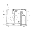
- FIG. 2 schematically shows the internal structure of the refrigeration device. In FIG.
- the right compartment of the heat insulation wall 2c is the machine room 2a
- the left compartment of the heat insulation wall 2c is the blower room 2b.
- a compressor 4 and an expansion valve 5 are arranged in the machine room 2a.
- a fan 7 driven by a motor (not shown) is disposed in the blower chamber 2b.
- a heat exchanger 10 is disposed below the blower chamber 2b with a heat insulating wall 2d therebetween. In the heat exchanger 10, heat exchange is performed between CO 2 circulating in the refrigerant circuit and water circulating in the water circulation circuit.
- the air heat exchanger 6 is arrange
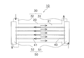
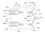
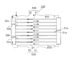
- the heat exchanger 10 includes a large number of flat tubes 20 and a large number of flat multi-hole tubes. 40, the entrance / exit part 30, and the entrance / exit distribution pipe 50 are comprised. 3 to 5 show an example in which five flat tubes 20 and four flat multi-hole tubes 40 are alternately stacked. However, the number of the flat tubes 20 and flat multi-hole tubes 40 to be laminated is appropriately selected according to required performance. Further, in this example, the flat tubes 20 are disposed at the lowermost and uppermost stages, but the flat multi-hole tube 40 may be disposed at the lowermost and uppermost stages. In addition, in FIG.
- corrugation of the outer surface of the flat tube 20 is abbreviate
- the flat multi-hole tube 40 is required to have high pressure resistance, the flat tube 20 through which water flows is required to have high corrosion resistance. For this reason, the flat multi-hole tube 40 requiring high pressure resistance is provided with a large number of thin flow paths 41.
- the flat multi-hole tube 40 is made of aluminum, an aluminum alloy, a copper alloy, stainless steel, or the like.
- aluminum or aluminum alloy drawing or extrusion is preferably used. When such processing is used, the flat multi-hole tube is inexpensively used. 40 can be manufactured.
- the base material of the flat tube 20 it is preferable to use stainless steel or a copper alloy in consideration of the corrosiveness of water.
- the stainless steel include SUS304 and SUS316.
- the flat tube 20 can be made of aluminum or an aluminum alloy, but in that case, it is preferable to apply anticorrosion treatment such as alumite processing or resin coating on the inner surface.
- the heat exchanger 10 is a right-side inlet / outlet that is disposed at the right end of the flat tube 20 as the inlet / outlet portion 30.
- positioned at the left end part are included.
- An entrance / exit port 34 connected to piping or the like is provided at the end of the left entrance / exit 32 and the end of the right entrance 31 shown in FIG.
- the heat exchanger 10 must be used in the state of FIG. 3. It is not a thing. For example, it is possible to use the heat exchanger 10 with the right inlet / outlet portion 31 disposed above and the left inlet / outlet portion 32 disposed below.
- the water On the side of the flat tube 20, the water first enters the left inlet / outlet port 32, is divided into five flat tubes 20, flows from the left to the right through the flat tube 20, and exits from the right inlet / outlet port 31. The water is heated by heat given from CO 2 of the flat multi-hole tube 40 while flowing through the flat tube 20.
- the heat exchanger 10 includes, as the inlet / outlet distribution pipe 50, a right side inlet / outlet distribution pipe 51 arranged at the right end of the flat multi-hole pipe 40 and a left side inlet / outlet distribution pipe 52 arranged at the left end.
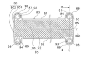
- FIG. 6 is a plan view of a metal plate for forming a flat tube and an entrance / exit part.
- the planar shape of the metal plate 80 is a substantially rectangular shape that is long to the left and right, and four bulging portions are formed at both left and right ends of the first long side 81 and the second long side 82.
- the metal plate 80 is formed by integrally connecting a first plate 801 and a second plate 802.
- the four bulging portions are a right first bulging portion 86, a left first bulging portion 87, a right second bulging portion 88, and a left second bulging portion 89.
- a right first opening 91 is formed in the right first bulging portion 86
- a left first opening 92 is formed in the left first bulging portion 87
- a right second opening is formed in the right second bulging portion 88.
- An opening 93 is formed, and a left second opening 94 is formed in the left second bulging portion 89.
- right first opening 91, left first opening 92, right second opening 93 and left second opening 94 are circular and all have the same size. Further, the right first opening 91 and the left first opening 92 are disposed so as to protrude outward from the extension line of the first long side 81, and the right second opening 93 and the left second opening 94 are The two long sides 82 are arranged so as to protrude outside the extended line. However, these shapes may be the same shape to make it difficult to leak water, and are not limited to a circle. Further, the position and size to be arranged are set according to the flow rate and the flow path. 7 is a cross-sectional view taken along the line II of FIG. As shown in FIG.
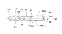
- the metal plate 80 has a concave surface portion 95 formed by pressing.
- the concave surface portion 95 occupies a region inside the peripheral edge portion 84 having a predetermined width formed along the outer periphery 83 of the metal plate 80.
- a central portion 85 that is in the middle of the first long side 81 and the second long side 82 and is formed in parallel with them is not a concave surface, and is formed at the same height as the peripheral portion 84. That is, the concave portion 95 is divided into a first concave portion 96 formed on the first plate 801 and a second concave portion 97 formed on the second plate 802 with the central portion 85 as a boundary.
- the right first opening 91 and the left first opening 92 are formed in the first concave surface portion 96, and the right second opening 93 and the left second opening 94 are formed in the second concave surface portion 97.
- the right first opening 91, the left first opening 92, the right second opening 93, and the left second opening 94 are recessed portions 98 that are further deepened in the first concave portion 96 and the second concave portion 97. Is arranged.
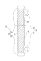
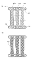
- FIG. 8 shows a state after the metal plate 80 shown in FIGS. 6 and 7 is bent.
- the metal plate 80 is bent along a straight line 100 extending left and right through the center of the central portion 85.
- the peripheral edge 84 overlaps so that the first long side 81 and the second long side 82 coincide with each other, and the first plate 801 and the second plate 802 are brought together.
- the flow path 21 is formed by the first concave surface portion 96 and the second concave surface portion 97 when the first plate 801 and the second plate 802 are combined.
- the flow path 21 continues to the right first opening 91, the left first opening 92, the right second opening 93, and the left second opening 94.
- the right first opening 91 and the right second opening 93, and the left first opening 92 and the left second opening 94 are arranged to face each other.
- the entrance / exit part 30 is formed straight by arrange
- the peripheral edge portion 84 that overlaps the bent metal plate 80 is sealed by winding or brazing to form one flat tube 20.
- the first concave surface portion 96 is formed with the ridge 22 protruding from the bottom surface side of the first concave surface portion 96 toward the peripheral edge portion 84 side. .
- the ridge 23 is formed that protrudes from the bottom surface side of the second concave surface portion 97 toward the peripheral edge portion 84 during pressing.
- the ridge 22 and the ridge 23 are inclined at the same angle with respect to the first long side 81 and the second long side 82 in FIG. 6. Therefore, when the metal plate 80 is bent, the protrusions 22 and the protrusions 23 are arranged so as to intersect with each other in plan view.
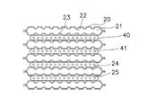
- ridges 22 and 23 generate a turbulent flow when water flows through the flow path 21, improving the efficiency of heat transfer between the water and the metal plate 80. Since the ridges 22 and 23 are formed on the bottom surface of the concave surface portion 95, the opposite surface of the concave surface portion 95, that is, the outer surface 29 of the flat tube 20 is dented, and the concave ridges 24 and 25 appear. The function of these concave stripes 24 and 25 will be described later.
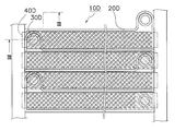
- FIG. 9 schematically shows the configuration of the heat exchanger 10. 20 and the flat multi-hole tube 40 have a straight shape. 9, the description of the uppermost flat tube 20 shown in FIG. 4 is omitted in order to explain the configuration of the recess 24.
- a right side entrance 31 and a left side entrance 32 are formed on the side of the flat multi-hole tube 40.
- the right inlet / outlet pipe 51 and the left inlet / outlet pipe 52 are provided at both ends of the flat multi-hole pipe 40. Therefore, since the flat multi-hole tube 40 can be formed straight at the time of manufacture, it is difficult to cause problems such as breakage of the flat multi-hole tube 40 due to stress when the flat multi-hole tube 40 is bent, and manufacture is easy. is there.
- FIG. 10 is a process diagram showing an outline of manufacturing a heat exchanger.
- FIG. 10A is a partial plan view showing a metal plate formed by a press working process.
- the metal plate 80 having the shape shown in FIG. 10A is formed by pressing a metal flat plate. That is, a flat metal flat plate is punched along the outer periphery 83 by a single press work, and the right first opening 91, the left first opening 92, the right second opening 93, and the left second opening 94. Is formed.
- the concave portion 95, the ridges 22 and 23, the ridges 24 and 25 (see FIG. 7), and the recess 98 are formed.
- FIG. 10B is a partial plan view showing the metal plate processed by the bending process.
- a state in which the metal plate 80 is bent and the first plate 801 and the second plate 802 are overlapped is shown.
- the peripheral edge 84 of the metal plate 80 is not yet joined.
- FIG.10 (c) is sectional drawing which shows the flat tube by which the peripheral part was joined by the 1st joining process.
- the overlapped peripheral portions 84 of the first plate 801 and the second plate 802 are joined by brazing or welding. A portion where the peripheral edge portion 84 is joined is the first joint portion 101.
- FIG. 10B is a partial plan view showing the metal plate processed by the bending process.
- 10D is a cross-sectional view showing the flat tube and the entrance / exit port in which the flat tubes and the entrance / exit port are joined by the second joining step.
- the flat tubes 20 are joined together by brazing or welding.
- the inlet / outlet port 34 is connected to the uppermost flat tube 20 by brazing or welding.
- a portion where the flat tubes 20 are joined together, that is, a joining portion between the right first opening 91 and the right second opening 93 and a joining portion between the left first opening 92 and the left second opening 94 are the second joining portions. 102.
- the joined body of the flat tube 20 is formed through the process of FIG.
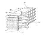
- FIG.10 (e) is a fragmentary perspective view for demonstrating the assembly process of the joined body of the flat tube in which the entrance / exit part was formed, a flat multi-hole pipe, and the entrance / exit distribution pipe.
- the flat multi-hole tube 40, the right inlet / outlet pipe 51 and the left inlet / outlet pipe 52 are joined by brazing or welding such as hand brazing or high frequency brazing. Bonding is performed to prepare a bonded body shown in FIG.
- the assembly of the flat tube 20 and the flat multi-hole tube 40 is combined to form an assembly.
- FIG. 10F is a partial perspective view showing the heat exchanger in which the flat tube and the flat multi-hole tube are joined in the joining step.
- the heat exchanger 10 is formed by integral brazing such as a 600 ° C. sawlock brazing.
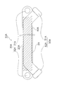
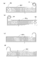
- FIG. 11 shows the structure around the right entrance 31. Since the structure around the left side entrance / exit part 32 is the same as that of the right side entrance / exit part 31, the description thereof is omitted.
- the flat tubes 20a and 20b are one flat tube and the other flat tube adjacent to each other. In the state where the metal wall (metal plate 80) constituting the flow path 21 of the flat tubes 20a and 20b and the flat multi-hole tube 40 are in contact, the right first opening 91 of the flat tube 20a and the right side of the flat tube 20b The second opening 93 comes into contact.
- the flat tubes 20b and 20c as in the case of the flat tubes 20a and 20b, the right first opening 91 of the flat tube 20b (one flat tube) and the right second opening of the flat tube 20c (the other flat tube).
- the portion 93 is joined, and the flat multi-hole tube 40b is sandwiched between the flat tubes 20b and 20c.
- the flat tubes 20a, 20b, and 20c shown in FIG. 11 are made of a metal that can be easily brazed, such as aluminum. Therefore, even if it matches any surface, such as the surface of metal plate 80 which forms flat tube 20a, 20b, 20c, and the back surfaces, it can join. (5) Features (5-1) As shown in FIG.
- the flat tubes 20 and the flat multi-hole tubes 40 are alternately stacked.
- Low-pressure water (first fluid) flows through one flow channel 21 (first flow channel) of the flat tube 20, and high-pressure CO 2 (second flow channel) flows through the flow channel 41 (second flow channel) of the flat multi-hole tube 40.
- the second fluid) is flowing.
- the high-pressure fluid flows through the flat multi-hole tube 40 and the low-pressure fluid flows through the flat tube 20, so that a plurality of the flow paths 41 of the flat multi-hole tube 40 can be formed to be thin.
- the exchanger 10 may be suitable for heat exchange between a high pressure fluid and a low pressure fluid.
- the right first opening 91 (first opening) of the adjacent flat tubes 20a (one flat tube) and the right second opening 93 (second opening) of the flat tubes 20b (the other flat tube). are directly brazed. Therefore, a separate member is not required for connection between the right first opening 91 and the right second opening 93, the arrangement interval between the flat tubes 20 adjacent to each other is reduced, and the flat tube 20 and the flat multi-hole tube 40 are stacked. The size of the directional heat exchanger 10 can be reduced. The same applies to the joining of the left first opening 92 and the left second opening 94. (5-2) As shown in FIG.
- the flat multi-hole tubes 40a and 40b are disposed, for example, between the adjacent flat tubes 20a and 20b or between the flat tubes 20b and 20c.
- the flat tubes 20a, 20b, and 20c are formed from a metal plate 80 that is a separate member from the flat multi-hole tubes 40a and 40b. Therefore, for example, even if a hole is opened due to corrosion or the like in any of the flat tubes 20a, 20b, 20c and water leaks, the leaked water passes through the flat multi-hole tubes 40a, 40b and reaches the flow path 41. And water and CO2 are prevented from being mixed.
- the flow path 21, the right first opening 91, and the right second opening 93 can be easily formed by pressing a metal plate such as the flat tubes 20a, 20b, and 20c, the heat exchanger is inexpensive. 10 can be provided.
- the concave strip 24 (concave groove) shown in FIG. 9 protrudes outward from the flat multi-hole tube 40 in a top view. That is, the groove 24 (concave groove) has a length that protrudes beyond the contact region where the flat multi-hole tube 40 and the flat tube 20 are joined. Therefore, when a hole is opened in the flat tube 20, the water is guided to the visible portion of the heat exchanger 10 through the recess 24. It can be detected that a hole has been opened in the flat tube 20 by the water appearing in the appearance of the heat exchanger 10. Thereby, it becomes easy to prevent generation
- a concave groove may be formed on the outer surface of the flat multi-hole tube 40.
- the concave groove can be formed on the outer surface of the flat multi-hole tube 40 by machining such as scraping a part of the outer surface of the flat multi-hole tube 40 with an end mill.
- the above-mentioned concave stripes 24 and 25 are formed by pressing, they can be manufactured at low cost.
- the forming method is not limited to pressing, and chemical processing such as machining such as cutting or etching can also be used. . (5-4) As shown in FIG.
- the flat multi-hole tube 40 is made of aluminum and can form a large number of thin channels 41 by drawing or extrusion. Therefore, it is easy to process the flat multi-hole tube 40 into a shape suitable for a high-pressure fluid.
- the flat tube 20 is formed of stainless steel or a copper alloy, a flat tube suitable for a corrosive low-pressure fluid such as water can be provided.
- stainless steel and copper alloy have good thermal conductivity, it is possible to increase the efficiency of heat exchange between water and CO 2 .
- a filler material may be clad on the peripheral portion 84 of the metal plate 80 in FIG. That is, the filler material is clad on the surface where the peripheral portions 84 of the first plate 801 and the second plate 802 come into contact when bent as shown in FIG.
- the base material is made of stainless steel, copper alloy or the like, and the part where the filler material is clad is brought to the joint surface, the step of bending the metal plate 80 as in the first joint part 101 of FIG. It can be omitted.
- An aluminum filler material 140 is also clad in the third joint portion 103 of FIG. 13, that is, in a region in contact with the flat multi-hole tubes 40 and 40 b made of aluminum.
- the flat tubes 20a, 20b, 20c and the flat multi-hole tubes 40a, 40b that are alternately stacked by the filler material 140 are joined, the flat tubes 20a, 20b, 20c and the flat multi-hole tube 40a, The adhesiveness of 40b can be improved. Thereby, the heat conduction resistance between the flat tubes 20a, 20b, 20c and the flat multi-hole tubes 40a, 40b can be reduced.
- the flat tube 20 and the flat multi-hole tube 40 are alternately stacked with the wide surfaces in contact with each other, and as shown in FIG.
- stacked alternately is demonstrated.
- the mode in which the flat tubes 20 and the flat multi-hole tubes 40 are alternately stacked is not limited thereto, and includes, for example, the modes illustrated in FIGS. 14 and 15.
- the heat exchanger 10B shown in FIG. 14 has a structure in which two flat multi-hole tubes 40 stacked on one flat tube 20B are alternately stacked vertically. However, the flat multi-hole tube 40 arranged in the uppermost stage and the lowermost stage is one layer. By being arranged in this way, water in one flat tube 20B is heated by CO 2 flowing in the two flat multi-hole tubes 40 sandwiching it, so that the heat exchanger 10B is related to heating water. It has a higher capacity than the heat exchanger 10.
- the flat tube 20B forms an interval corresponding to two flat multi-hole tubes 40 between the flat tubes 20B adjacent to each other, the right first opening 91 of the flat tube 20 and the left first The recess 98 in which the opening 92, the right second opening 93, and the left second opening 94 are formed is further deepened.
- the flat tube 20 ⁇ / b> C and the flat multi-hole tube 40 are formed as a set of a laminated body P ⁇ b> 1 in which one flat tube 20 ⁇ / b> C is stacked so that two flat multi-hole tubes are sandwiched therebetween.
- a large number of laminates P1 may be arranged side by side. Although only three sets are shown in FIG.
- the metal plate 80d in FIG. 16A corresponds to the first plate 801 in FIG. 6, but includes a right first bulging portion 86, a left first bulging portion 87, a right second bulging portion 88, and A left second bulging portion 89 is provided. Then, the right first bulging portion 86, the left first bulging portion 87, the right second bulging portion 88, and the left second bulging portion 89 have a right first opening 91, a left first opening 92, respectively.
- a right second opening 93 and a left second opening 94 are formed.
- such metal plates 80d are arranged so that the concave surface portions 95 are alternately directed upward and downward.
- the concave portion 95 of the metal plate 80d at the left end and the right end faces upward, and the concave portion 95 of the central metal plate 80d faces downward.
- the right first opening 91, the left first opening 92, the right second opening 93, and the left second opening 94 of the three metal plates 80d are fitted together.
- the metal plate 80e is covered and brazed.
- flat multi-hole tubes 40 are stacked on the upper and lower sides of flat tubes 20 arranged in a plane as shown in FIG.
- the flat multi-hole tube 40 and the flat tube 20 may be joined simultaneously with the brazing of the metal plates 80d and 80e.
- FIG. 18 is a process diagram showing an outline of another manufacturing process of the heat exchanger.
- FIG. 18A is a plan view showing a metal plate formed by press working.
- FIG. 18B is a partial plan view of the metal plate formed in the bending process.
- FIG. 18D is a partial perspective view for explaining an assembly process of the flat multi-hole pipe and the inlet / outlet pipe.
- FIG. 18 (e) is a partial perspective view showing a flat tube, a flat multi-hole tube, and an inlet / outlet pipe that are integrally brazed.
- the steps shown in FIGS. 18A and 18B are the same as the steps described with reference to FIGS. 10A and 10B, and thus the description thereof is omitted. In parallel with the step of FIG.
- the flat multi-hole pipe 40, the right inlet / outlet pipe 51 and the left inlet / outlet pipe 52 shown in FIG. 18D are assembled.
- the flat multi-hole tube 40 is fitted into a plurality of openings (not shown) of the right-side inlet / outlet distribution pipe 51 and the left-side inlet / outlet distribution pipe 52 formed in accordance with the outer shape of the flat multi-hole pipe 40.
- an assembly is formed in which a plurality of flat multi-hole pipes 40 are fitted in the right side inlet / outlet distribution pipe 51 and the left side inlet / outlet distribution pipe 52 in a state where they are not fixed to each other.
- the bent metal plates 80 are placed on an assembly (see FIG. 18E) composed of the flat multi-hole tube 40, the right inlet / outlet distribution pipe 51, and the like. .
- a final assembly including the right inlet / outlet pipe 51, the left inlet / outlet pipe 52, the flat multi-hole pipe 40, and the flat pipe 20 is formed.
- the members are not joined together.
- Each part of the final assembly is placed in a furnace, and the heat exchanger 10 shown in FIG. 18E is formed by, for example, integral brazing such as a 600 ° C. sawlock brazing.
- the parts to be joined by brazing are the first joining part 101 (peripheral part 84 of the metal plate 80) and the second joining part 102 (the right side first entrance part 31 and the right side first entrance part 32 that constitute the left side entrance part 32). 91, right second opening 93 and left first opening 92 and left second opening 94), third joint 103 (right inlet / outlet distribution pipe 51 and left inlet / outlet distribution pipe 52 and flat multi-hole pipe 40), and It is the 4th junction part 104 (surface in which the flat tube 20 and the flat multi-hole tube 40 contact each other).
- the direction in which water flows through the flat tube 20D is all from left to right, and CO 2 flows through the flat multi-hole tube 40D. All directions are from right to left.
- the sum of the cross-sectional areas of the flow paths 21 of the five flat tubes 20D is simply five times that of one flat tube 20D.
- the sum of the cross-sectional areas of the flow paths 41 of the flat multi-hole tube 40D is also proportional to the number of flat multi-hole tubes 40D.
- FIG. 19 is a conceptual diagram schematically showing the configuration of the heat exchanger according to the second embodiment.
- the heat exchanger 10D of the second embodiment has an advantageous configuration when it is desired to make the contact portion for heat exchange longer than the flow rate of the refrigerant.
- a heat exchanger 10D shown in FIG. 19 includes a partition member 32a that closes the left inlet / outlet portion 32 between the second and third flat tubes 20D from the top, and the fourth and fifth flat portions from the top.
- a partition member 31a that closes the right entrance / exit portion 31 between the pipes 20D and a partition member 32b that closes the left entrance / exit portion 31 between the sixth and seventh flat tubes 20D from above are provided. Thereby, the flow path through which water flows can be reciprocated. Specifically, water enters from above the left entrance 32 and flows from the left to the right through the first and second flat tubes 20D from the top, and the third and fourth flat tubes from the top.
- the heat exchanger 10D includes a partition member 52a that closes the left inlet / outlet distribution pipe 52 between the second and third flat multi-hole pipes 40D from the bottom, and the fourth and fifth flat multi-holes from the bottom.
- a partition member 51a for closing the right-side entrance / exit pipe 51 between the pipes 40D and a partition member 52b for closing the left-side entrance / exit pipe 52 between the sixth and seventh flat multi-hole pipes 40D from the bottom are provided.
- CO 2 enters from the bottom of the left inlet / outlet distribution pipe 52, flows from the left to the right in the first and second flat multi-hole pipes 40D from the bottom, and the third and fourth stages from the bottom.
- Flows from right to left in the flat multi-hole tube 40D of the eye flows from left to right in the fifth and sixth flat multi-hole tubes 40D from the bottom, and from the top to the seventh and eighth steps Flowed from right to left through the flat multi-hole tube 40D of the eye, cooled CO 2 comes out from above the left inlet / outlet distribution pipe 52.
- FIGS. 20 (a), 20 (b), 20 (c) and 20 (d) four types are provided.
- the metal plates 80f, 80g, 80h, and 80i can be arranged as shown in FIG.
- the right second opening 93 and the left second opening 94 of the metal plate 80g are fitted into the right first opening 91 and the left first opening 92 of the metal plate 80f.
- the metal plate 80h is overlaid on the metal plate 80f
- the metal plate 80i is overlaid on the metal plate 80g and brazed.
- the flat tube 20D shown in FIG. 21 is formed.
- a flat multi-hole tube 40D is laminated above and below the flat tube 20D as shown in FIG.
- the heat exchanger 10D of FIG. 21 flows through the adjacent flat tube 20D.
- the entrance / exit part 30D and the flat multi-hole tube 40D intersect in plan view. Therefore, as shown in FIG. 22, the flat multi-hole tube 40D is slightly bent so as to avoid the inlet / outlet portion 30D, and is connected to the inlet / outlet pipe 50D.
- the partition members 31a, 32a, and 32b can be easily formed by not opening the first opening and the second opening. This is the same for CO 2 , and CO 2 is divided into the first and second stages from the bottom by the partition members 52a and 52b that block the left inlet / outlet distribution pipe 52 and the partition member 51a that blocks the right inlet / outlet distribution pipe 51. To the right, the 3rd and 4th steps from the bottom to the left, the 5th and 6th steps from the bottom to the right, and the 7th and 8th steps from the bottom to the left.
- the flat multi-hole tube 40D is reciprocated twice.
- the flat multi-hole tube 40D flows four times as much distance, and the CO 2 heat is sufficiently absorbed.
- the heat exchange efficiency can be increased.
- the partition members 31a, 32a, and 32b are arranged so that the flow direction changes for each of the two stages of the flat tubes 20D. Alternatively, the flow direction may be changed every three or more stages. The same applies to the partition members 51a, 52a, and 52b.
- the water is entered from the left entrance / exit portion 32 and exits from the left entrance / exit portion 32.
- the water may enter from the left entrance / exit portion 32 and exit from the right entrance / exit portion 31. .
Landscapes
- Engineering & Computer Science (AREA)
- Physics & Mathematics (AREA)
- Thermal Sciences (AREA)
- Mechanical Engineering (AREA)
- General Engineering & Computer Science (AREA)
- Heat-Exchange Devices With Radiators And Conduit Assemblies (AREA)
Abstract
La présente invention a trait à un échangeur de chaleur léger et compact pouvant échanger la chaleur entre un fluide haute pression et un fluide basse pression, par exemple entre du CO2 et de l'eau. Une section de sortie/d'entrée (31) est formée en joignant la première ouverture droite (91) et la seconde ouverture droite (93) de tuyaux plats (20a, 20b, 20c) à travers lesquels un fluide basse pression, tel que de l'eau, circule. La section de sortie/d'entrée (31) est connectée à une voie de passage (21). Les tuyaux plats (20a, 20b, 20c) et des tuyaux plats à trous multiples (40a, 40b), à travers lesquels circule un fluide haute pression, tel que du CO2, sont empilés en alternance.
Applications Claiming Priority (2)
| Application Number | Priority Date | Filing Date | Title |
|---|---|---|---|
| JP2011-067477 | 2011-03-25 | ||
| JP2011067477A JP5206830B2 (ja) | 2011-03-25 | 2011-03-25 | 熱交換器 |
Publications (1)
| Publication Number | Publication Date |
|---|---|
| WO2012132924A1 true WO2012132924A1 (fr) | 2012-10-04 |
Family
ID=46930659
Family Applications (1)
| Application Number | Title | Priority Date | Filing Date |
|---|---|---|---|
| PCT/JP2012/056679 WO2012132924A1 (fr) | 2011-03-25 | 2012-03-15 | Échangeur de chaleur |
Country Status (2)
| Country | Link |
|---|---|
| JP (1) | JP5206830B2 (fr) |
| WO (1) | WO2012132924A1 (fr) |
Cited By (8)
| Publication number | Priority date | Publication date | Assignee | Title |
|---|---|---|---|---|
| WO2014095572A1 (fr) * | 2012-12-21 | 2014-06-26 | Valeo Systemes Thermiques | Echangeur de chaleur, notamment pour fluide refrigerant circulant dans un vehicule automobile |
| EP3068941A1 (fr) * | 2013-11-13 | 2016-09-21 | Electrolux Appliances Aktiebolag | Appareil de lavage à pompe à chaleur |
| EP2942594A4 (fr) * | 2012-12-25 | 2016-10-26 | Daikin Ind Ltd | Echangeur thermique |
| WO2016198536A1 (fr) * | 2015-06-12 | 2016-12-15 | Valeo Systemes Thermiques | Echangeur de chaleur pour vehicule automobile |
| WO2017213164A1 (fr) * | 2016-06-10 | 2017-12-14 | サンデンホールディングス株式会社 | Échangeur de chaleur pour véhicule |
| US11054192B2 (en) | 2017-03-27 | 2021-07-06 | Daikin Industries, Ltd. | Heat exchanger and air conditioner |
| US11181328B2 (en) | 2017-03-27 | 2021-11-23 | Daikin Industries, Ltd. | Heat exchanger and air conditioner |
| EP4134610A4 (fr) * | 2020-08-26 | 2023-10-18 | GD Midea Heating & Ventilating Equipment Co., Ltd. | Échangeur de chaleur, boîtier de commande électrique et système de climatisation |
Families Citing this family (2)
| Publication number | Priority date | Publication date | Assignee | Title |
|---|---|---|---|---|
| ES2593064T3 (es) * | 2013-11-28 | 2016-12-05 | Alfa Laval Corporate Ab | Sistema y método para el control dinámico de un intercambiador de calor |
| JP2016017737A (ja) * | 2014-07-07 | 2016-02-01 | 現代自動車株式会社Hyundaimotor Company | Ted熱交換器 |
Citations (7)
| Publication number | Priority date | Publication date | Assignee | Title |
|---|---|---|---|---|
| JPS5932877U (ja) * | 1982-08-23 | 1984-02-29 | カルソニックカンセイ株式会社 | 熱交換器 |
| JP2001050681A (ja) * | 1999-08-06 | 2001-02-23 | Matsushita Electric Ind Co Ltd | 熱交換器およびその熱交換器を用いた冷凍サイクル装置 |
| JP2003329378A (ja) * | 2002-05-09 | 2003-11-19 | Denso Corp | 熱交換器 |
| JP2007017132A (ja) * | 2005-07-11 | 2007-01-25 | Denso Corp | 熱交換用チューブおよび熱交換器 |
| JP2007017133A (ja) * | 2005-07-11 | 2007-01-25 | Denso Corp | 熱交換器 |
| JP2008134016A (ja) * | 2006-11-29 | 2008-06-12 | Denso Corp | 熱交換器および熱交換器の製造方法。 |
| JP2010216773A (ja) * | 2009-03-18 | 2010-09-30 | Daikin Ind Ltd | 水熱交換器および水熱交換器の製造方法 |
-
2011
- 2011-03-25 JP JP2011067477A patent/JP5206830B2/ja active Active
-
2012
- 2012-03-15 WO PCT/JP2012/056679 patent/WO2012132924A1/fr active Application Filing
Patent Citations (7)
| Publication number | Priority date | Publication date | Assignee | Title |
|---|---|---|---|---|
| JPS5932877U (ja) * | 1982-08-23 | 1984-02-29 | カルソニックカンセイ株式会社 | 熱交換器 |
| JP2001050681A (ja) * | 1999-08-06 | 2001-02-23 | Matsushita Electric Ind Co Ltd | 熱交換器およびその熱交換器を用いた冷凍サイクル装置 |
| JP2003329378A (ja) * | 2002-05-09 | 2003-11-19 | Denso Corp | 熱交換器 |
| JP2007017132A (ja) * | 2005-07-11 | 2007-01-25 | Denso Corp | 熱交換用チューブおよび熱交換器 |
| JP2007017133A (ja) * | 2005-07-11 | 2007-01-25 | Denso Corp | 熱交換器 |
| JP2008134016A (ja) * | 2006-11-29 | 2008-06-12 | Denso Corp | 熱交換器および熱交換器の製造方法。 |
| JP2010216773A (ja) * | 2009-03-18 | 2010-09-30 | Daikin Ind Ltd | 水熱交換器および水熱交換器の製造方法 |
Cited By (14)
| Publication number | Priority date | Publication date | Assignee | Title |
|---|---|---|---|---|
| FR3000187A1 (fr) * | 2012-12-21 | 2014-06-27 | Valeo Systemes Thermiques | Echangeur de chaleur, notamment pour fluide refrigerant circulant dans un vehicule automobile |
| CN104995472A (zh) * | 2012-12-21 | 2015-10-21 | 法雷奥热系统公司 | 热交换器,特别地用于在机动车辆中循环的制冷剂 |
| WO2014095572A1 (fr) * | 2012-12-21 | 2014-06-26 | Valeo Systemes Thermiques | Echangeur de chaleur, notamment pour fluide refrigerant circulant dans un vehicule automobile |
| CN104995472B (zh) * | 2012-12-21 | 2017-08-04 | 法雷奥热系统公司 | 热交换器,特别地用于在机动车辆中循环的制冷剂 |
| US9791213B2 (en) | 2012-12-25 | 2017-10-17 | Daikin Industries, Ltd. | Heat exchanger |
| EP2942594A4 (fr) * | 2012-12-25 | 2016-10-26 | Daikin Ind Ltd | Echangeur thermique |
| EP3068941A1 (fr) * | 2013-11-13 | 2016-09-21 | Electrolux Appliances Aktiebolag | Appareil de lavage à pompe à chaleur |
| EP3068941B1 (fr) * | 2013-11-13 | 2022-04-06 | Electrolux Appliances Aktiebolag | Appareil de lavage à pompe à chaleur |
| FR3037387A1 (fr) * | 2015-06-12 | 2016-12-16 | Valeo Systemes Thermiques | Echangeur de chaleur pour vehicule automobile |
| WO2016198536A1 (fr) * | 2015-06-12 | 2016-12-15 | Valeo Systemes Thermiques | Echangeur de chaleur pour vehicule automobile |
| WO2017213164A1 (fr) * | 2016-06-10 | 2017-12-14 | サンデンホールディングス株式会社 | Échangeur de chaleur pour véhicule |
| US11054192B2 (en) | 2017-03-27 | 2021-07-06 | Daikin Industries, Ltd. | Heat exchanger and air conditioner |
| US11181328B2 (en) | 2017-03-27 | 2021-11-23 | Daikin Industries, Ltd. | Heat exchanger and air conditioner |
| EP4134610A4 (fr) * | 2020-08-26 | 2023-10-18 | GD Midea Heating & Ventilating Equipment Co., Ltd. | Échangeur de chaleur, boîtier de commande électrique et système de climatisation |
Also Published As
| Publication number | Publication date |
|---|---|
| JP5206830B2 (ja) | 2013-06-12 |
| JP2012202608A (ja) | 2012-10-22 |
Similar Documents
| Publication | Publication Date | Title |
|---|---|---|
| JP5206830B2 (ja) | 熱交換器 | |
| JP5394405B2 (ja) | 熱交換器 | |
| JP6615423B1 (ja) | プレート式熱交換器、プレート式熱交換器を備えたヒートポンプ装置、及び、ヒートポンプ装置を備えたヒートポンプ式冷暖房給湯システム | |
| JP6594598B1 (ja) | プレート式熱交換器、プレート式熱交換器を備えたヒートポンプ装置、及び、ヒートポンプ装置を備えたヒートポンプ式暖房給湯システム | |
| JP6529709B1 (ja) | プレート式熱交換器、ヒートポンプ装置およびヒートポンプ式冷暖房給湯システム | |
| WO2018216245A1 (fr) | Échangeur de chaleur à plaques et système d'alimentation en eau chaude de pompe à chaleur | |
| EP2676094B1 (fr) | Procédé de fabrication d'un échangeur de chaleur et échangeur de chaleur | |
| JP5661205B2 (ja) | 積層型熱交換器及びそれを搭載したヒートポンプシステム、並びに積層型熱交換器の製造方法 | |
| JP2010121925A (ja) | 熱交換器 | |
| JP4936546B2 (ja) | 熱交換器 | |
| JP6028452B2 (ja) | 水熱交換器 | |
| JP2014052147A (ja) | 熱交換器及びその製造方法 | |
| JP6107017B2 (ja) | 熱交換器、および、熱交換器の製造方法 | |
| JP2009079779A (ja) | プレート式熱交換器及びこのプレート式熱交換器を用いた空気調和装置 | |
| JP2001133172A (ja) | 熱交換器および冷凍空調装置 | |
| JP6601380B2 (ja) | 熱交換器および空気調和装置 | |
| JP2014066409A (ja) | 熱交換器、および、熱交換器の製造方法 | |
| JP6028473B2 (ja) | 熱交換器 | |
| JP2003314975A (ja) | 熱交換器 | |
| JP2012200760A (ja) | 熱交換器の製造方法 | |
| JP2014066408A (ja) | 熱交換器、および、熱交換器の製造方法 | |
| JP2000154978A (ja) | 熱交換器 | |
| JP2009243792A (ja) | 熱交換器 | |
| JP2014126237A (ja) | 熱交換器 | |
| JP2015068621A (ja) | 水熱交換器 |
Legal Events
| Date | Code | Title | Description |
|---|---|---|---|
| 121 | Ep: the epo has been informed by wipo that ep was designated in this application |
Ref document number: 12765353 Country of ref document: EP Kind code of ref document: A1 |
|
| NENP | Non-entry into the national phase |
Ref country code: DE |
|
| 122 | Ep: pct application non-entry in european phase |
Ref document number: 12765353 Country of ref document: EP Kind code of ref document: A1 |