WO2012132450A1 - エンジン用シリンダ内圧センサ - Google Patents
エンジン用シリンダ内圧センサ Download PDFInfo
- Publication number
- WO2012132450A1 WO2012132450A1 PCT/JP2012/002182 JP2012002182W WO2012132450A1 WO 2012132450 A1 WO2012132450 A1 WO 2012132450A1 JP 2012002182 W JP2012002182 W JP 2012002182W WO 2012132450 A1 WO2012132450 A1 WO 2012132450A1
- Authority
- WO
- WIPO (PCT)
- Prior art keywords
- pressure
- internal pressure
- ring block
- pressure sensor
- engine
- Prior art date
Links
- 238000001514 detection method Methods 0.000 claims abstract description 98
- 230000002093 peripheral effect Effects 0.000 claims abstract description 19
- 125000006850 spacer group Chemical group 0.000 claims description 37
- 239000000463 material Substances 0.000 claims description 21
- 238000002485 combustion reaction Methods 0.000 claims description 20
- 238000009792 diffusion process Methods 0.000 claims description 13
- 239000013078 crystal Substances 0.000 claims description 10
- 239000000446 fuel Substances 0.000 claims description 7
- 230000003014 reinforcing effect Effects 0.000 claims description 4
- 230000002265 prevention Effects 0.000 claims description 3
- 230000004323 axial length Effects 0.000 claims 2
- 230000004927 fusion Effects 0.000 claims 1
- 238000013459 approach Methods 0.000 abstract 1
- 238000004519 manufacturing process Methods 0.000 description 6
- 230000009467 reduction Effects 0.000 description 5
- 239000000956 alloy Substances 0.000 description 4
- 229910015363 Au—Sn Inorganic materials 0.000 description 3
- 230000009471 action Effects 0.000 description 3
- 230000000694 effects Effects 0.000 description 3
- 239000010931 gold Substances 0.000 description 3
- 230000006872 improvement Effects 0.000 description 3
- 239000012212 insulator Substances 0.000 description 3
- 238000000034 method Methods 0.000 description 3
- 229910052763 palladium Inorganic materials 0.000 description 3
- BASFCYQUMIYNBI-UHFFFAOYSA-N platinum Substances [Pt] BASFCYQUMIYNBI-UHFFFAOYSA-N 0.000 description 3
- 229910052718 tin Inorganic materials 0.000 description 3
- 239000010936 titanium Substances 0.000 description 3
- 229910052684 Cerium Inorganic materials 0.000 description 2
- 229910045601 alloy Inorganic materials 0.000 description 2
- 238000005452 bending Methods 0.000 description 2
- 229910010293 ceramic material Inorganic materials 0.000 description 2
- 238000006243 chemical reaction Methods 0.000 description 2
- 229910052804 chromium Inorganic materials 0.000 description 2
- 238000005520 cutting process Methods 0.000 description 2
- 229910052737 gold Inorganic materials 0.000 description 2
- 238000010438 heat treatment Methods 0.000 description 2
- 229910052759 nickel Inorganic materials 0.000 description 2
- 229910052709 silver Inorganic materials 0.000 description 2
- 230000000087 stabilizing effect Effects 0.000 description 2
- 229910052719 titanium Inorganic materials 0.000 description 2
- 238000003466 welding Methods 0.000 description 2
- 229910017980 Ag—Sn Inorganic materials 0.000 description 1
- 229910002710 Au-Pd Inorganic materials 0.000 description 1
- 229910017401 Au—Ge Inorganic materials 0.000 description 1
- 229910017755 Cu-Sn Inorganic materials 0.000 description 1
- 229910017932 Cu—Sb Inorganic materials 0.000 description 1
- 229910017927 Cu—Sn Inorganic materials 0.000 description 1
- RTAQQCXQSZGOHL-UHFFFAOYSA-N Titanium Chemical compound [Ti] RTAQQCXQSZGOHL-UHFFFAOYSA-N 0.000 description 1
- 230000008901 benefit Effects 0.000 description 1
- 238000005219 brazing Methods 0.000 description 1
- 230000008859 change Effects 0.000 description 1
- 239000011248 coating agent Substances 0.000 description 1
- 238000000576 coating method Methods 0.000 description 1
- 239000000567 combustion gas Substances 0.000 description 1
- 239000002131 composite material Substances 0.000 description 1
- 239000000470 constituent Substances 0.000 description 1
- 229910052802 copper Inorganic materials 0.000 description 1
- 238000005336 cracking Methods 0.000 description 1
- 230000007547 defect Effects 0.000 description 1
- 238000012217 deletion Methods 0.000 description 1
- 230000037430 deletion Effects 0.000 description 1
- 238000006073 displacement reaction Methods 0.000 description 1
- 238000005516 engineering process Methods 0.000 description 1
- 230000005496 eutectics Effects 0.000 description 1
- PCHJSUWPFVWCPO-UHFFFAOYSA-N gold Chemical compound [Au] PCHJSUWPFVWCPO-UHFFFAOYSA-N 0.000 description 1
- JVPLOXQKFGYFMN-UHFFFAOYSA-N gold tin Chemical compound [Sn].[Au] JVPLOXQKFGYFMN-UHFFFAOYSA-N 0.000 description 1
- 229910052738 indium Inorganic materials 0.000 description 1
- 239000011810 insulating material Substances 0.000 description 1
- 229910052742 iron Inorganic materials 0.000 description 1
- GQYHUHYESMUTHG-UHFFFAOYSA-N lithium niobate Chemical compound [Li+].[O-][Nb](=O)=O GQYHUHYESMUTHG-UHFFFAOYSA-N 0.000 description 1
- 229910052751 metal Inorganic materials 0.000 description 1
- 239000002184 metal Substances 0.000 description 1
- 150000002739 metals Chemical class 0.000 description 1
- 230000004048 modification Effects 0.000 description 1
- 238000012986 modification Methods 0.000 description 1
- 230000000149 penetrating effect Effects 0.000 description 1
- 230000035515 penetration Effects 0.000 description 1
- 229910052697 platinum Inorganic materials 0.000 description 1
- 230000010287 polarization Effects 0.000 description 1
- 230000008569 process Effects 0.000 description 1
- 229910000679 solder Inorganic materials 0.000 description 1
- 230000002269 spontaneous effect Effects 0.000 description 1
- 238000005728 strengthening Methods 0.000 description 1
- 229910052720 vanadium Inorganic materials 0.000 description 1
- 229910052726 zirconium Inorganic materials 0.000 description 1
Images


Classifications
-
- F—MECHANICAL ENGINEERING; LIGHTING; HEATING; WEAPONS; BLASTING
- F02—COMBUSTION ENGINES; HOT-GAS OR COMBUSTION-PRODUCT ENGINE PLANTS
- F02F—CYLINDERS, PISTONS OR CASINGS, FOR COMBUSTION ENGINES; ARRANGEMENTS OF SEALINGS IN COMBUSTION ENGINES
- F02F1/00—Cylinders; Cylinder heads
-
- F—MECHANICAL ENGINEERING; LIGHTING; HEATING; WEAPONS; BLASTING
- F02—COMBUSTION ENGINES; HOT-GAS OR COMBUSTION-PRODUCT ENGINE PLANTS
- F02D—CONTROLLING COMBUSTION ENGINES
- F02D35/00—Controlling engines, dependent on conditions exterior or interior to engines, not otherwise provided for
- F02D35/02—Controlling engines, dependent on conditions exterior or interior to engines, not otherwise provided for on interior conditions
- F02D35/023—Controlling engines, dependent on conditions exterior or interior to engines, not otherwise provided for on interior conditions by determining the cylinder pressure
-
- G—PHYSICS
- G01—MEASURING; TESTING
- G01L—MEASURING FORCE, STRESS, TORQUE, WORK, MECHANICAL POWER, MECHANICAL EFFICIENCY, OR FLUID PRESSURE
- G01L23/00—Devices or apparatus for measuring or indicating or recording rapid changes, such as oscillations, in the pressure of steam, gas, or liquid; Indicators for determining work or energy of steam, internal-combustion, or other fluid-pressure engines from the condition of the working fluid
- G01L23/08—Devices or apparatus for measuring or indicating or recording rapid changes, such as oscillations, in the pressure of steam, gas, or liquid; Indicators for determining work or energy of steam, internal-combustion, or other fluid-pressure engines from the condition of the working fluid operated electrically
- G01L23/10—Devices or apparatus for measuring or indicating or recording rapid changes, such as oscillations, in the pressure of steam, gas, or liquid; Indicators for determining work or energy of steam, internal-combustion, or other fluid-pressure engines from the condition of the working fluid operated electrically by pressure-sensitive members of the piezoelectric type
-
- G—PHYSICS
- G01—MEASURING; TESTING
- G01L—MEASURING FORCE, STRESS, TORQUE, WORK, MECHANICAL POWER, MECHANICAL EFFICIENCY, OR FLUID PRESSURE
- G01L23/00—Devices or apparatus for measuring or indicating or recording rapid changes, such as oscillations, in the pressure of steam, gas, or liquid; Indicators for determining work or energy of steam, internal-combustion, or other fluid-pressure engines from the condition of the working fluid
- G01L23/22—Devices or apparatus for measuring or indicating or recording rapid changes, such as oscillations, in the pressure of steam, gas, or liquid; Indicators for determining work or energy of steam, internal-combustion, or other fluid-pressure engines from the condition of the working fluid for detecting or indicating knocks in internal-combustion engines; Units comprising pressure-sensitive members combined with ignitors for firing internal-combustion engines
- G01L23/221—Devices or apparatus for measuring or indicating or recording rapid changes, such as oscillations, in the pressure of steam, gas, or liquid; Indicators for determining work or energy of steam, internal-combustion, or other fluid-pressure engines from the condition of the working fluid for detecting or indicating knocks in internal-combustion engines; Units comprising pressure-sensitive members combined with ignitors for firing internal-combustion engines for detecting or indicating knocks in internal combustion engines
- G01L23/222—Devices or apparatus for measuring or indicating or recording rapid changes, such as oscillations, in the pressure of steam, gas, or liquid; Indicators for determining work or energy of steam, internal-combustion, or other fluid-pressure engines from the condition of the working fluid for detecting or indicating knocks in internal-combustion engines; Units comprising pressure-sensitive members combined with ignitors for firing internal-combustion engines for detecting or indicating knocks in internal combustion engines using piezoelectric devices
Definitions
- the present invention relates to an engine cylinder internal pressure sensor configured in a ring shape suitable for use in detecting the internal pressure of a cylinder.
- an engine cylinder internal pressure sensor that detects an internal pressure (combustion pressure) of a cylinder by facing the combustion chamber of the engine.
- This type of cylinder internal pressure sensor is a through-hole formed at a predetermined position of a cylinder. It needs to be installed independently due to its high airtight structure. For this reason, the cylinder pressure sensor is configured in a ring shape, and can be mounted integrally on the outer peripheral surface of the tip of the spark plug, which is another functional part attached to the engine, and can be mounted on the cylinder together with the spark plug.
- Such a cylinder internal pressure sensor is also known.
- the combustion pressure sensor of Patent Document 1 is built in an ignition plug having an insulator formed around a center electrode, and a washer member electrically connected to the side electrode and formed around the insulator.
- the combustion pressure sensor is configured to include a piezoelectric element made of lithium niobate disposed between an insulator and a washer member and in the vicinity of an ignition gap between a center electrode and a side electrode.
- the pressure sensor disclosed in Patent Document 2 is a pressure sensor that is fastened together with a mounting hole instead of a gasket of a spark plug.
- the pressure sensor has a mounting surface of a housing pressed against a cylinder head, and the housing is radiated with heat. It has a configuration in which fins are fixed.
- the spark plug with a built-in pressure sensor disclosed in Patent Document 3 is installed in the seat portion facing the plug mounting surface provided in the internal combustion engine when installed in the internal combustion engine.
- the Ri, and a, and the lead member for taking out the output of the piezoelectric element is connected to an insulating plate provided on the upper surface of the electrode plate with the terminal of the electrode plate protruding upward from the notch, and a terminal protruding from the notch of the insulating plate.
- JP-A-4-34327 Japanese Patent Laid-Open No. 11-94675 JP 2000-277233 A
- the pressure detecting element used is made of a single crystal material having high heat resistance and good piezoelectric conversion characteristics even in a high temperature environment. desirable.
- the single crystal material is highly brittle, cutting a single crystal material and cutting out the ring-shaped pressure detection element as in Patent Documents 1 and 2 described above requires a high degree of processing technology. Manufacture is not easy. Eventually, the yield and mass productivity are reduced, and the cost increase cannot be ignored.
- it is necessary to form the whole in a thin ring shape there is a possibility that problems such as cracking may occur when it is attached to an engine with large vibrations, and it cannot necessarily be said to be a highly reliable pressure detection element.
- Patent Document 3 since the pressure detection element is formed as a rectangular parallelepiped chip body and a plurality of chip bodies are arranged in a ring shape, manufacturing (processing) in the case of integrally forming the ring shape described above. Although the above problems do not occur, on the other hand, variations in the dimensions and angles of each chip body directly affect the characteristics (performance) of the cylinder internal pressure sensor, which tends to cause a decrease in detection accuracy and product variations. .
- An object of the present invention is to provide an engine cylinder internal pressure sensor that solves the problems existing in the background art.
- the present invention has a ring shape that detects the internal pressure Pc of the cylinder Ec by being mounted on the outer peripheral surfaces Mas and Mbs of the front end portions of the functional parts Ma and Mb facing the combustion chamber Rb of the engine.
- a housing including an outer cylinder portion 2e and an inner cylinder portion 2i formed by forming elastic portions 2es and 2is having elasticity in the axial direction Fs at an intermediate portion Xm in the axial direction Fs.
- the unit 2 is hermetically fixed between the outer cylindrical portion 2e and the inner cylindrical portion 2i positioned in front of the elastic portions 2es and 2is, and is exposed to the rear of the elastic portions 2e and 2i through the elastic portions 2e and 2i.
- the pressure receiving ring block portion 3 whose front surface 3f is a pressure receiving surface and one electrode portion 4 provided on the rear surface 3r of the pressure receiving ring block portion 3 are in contact with the pressure receiving ring block portion.
- the internal pressure Pc is applied from the portion 3, and is fixed between at least one or more pressure detection elements 5a, 5b, 5c... Disposed at a predetermined position in the circumferential direction Ff, and the outer cylindrical portion 2e and the inner cylindrical portion 2i.
- the front surface 6f serves as a support surface for supporting the pressure detection elements 5a, and includes a support ring block portion 6 that also serves as the other electrode 7.
- one or more spacers 10a ..., 10as ... along the circumferential direction Ff are provided at portions other than the pressure detection elements 5a ... in contact with the rear surface portion of the pressure-receiving ring block portion 3. , 10 at is desirable.
- the pressure detection elements 5a and the spacers 10a,..., 10at are alternately arranged along the circumferential direction Ff of the pressure-receiving ring block portion 3, and the shafts of the spacers 10a,.
- the length in the direction Fs is selected according to the length in the axial direction Fs of the pressure detection elements 5a.
- the elastic portions 2es and 2is can be provided by forming bent portions (or curved portions) 11e and 11i in an intermediate portion Xm between the outer tube portion 2e and the inner tube portion 2i.
- the pressure receiving ring block portion 3 can be constituted by a pressure receiving ring main body portion 12 disposed on the front side, and an insulating block portion 13 which is disposed on the rear side so as to abut against the pressure receiving ring main body portion 12, and pressure detection.
- a single crystal material can be used for the elements 5a.
- the bonding layer C can be coated with the intermediate layer Cm serving as the diffusion preventing layer and the outer layer Ce serving as the diffusion layer.
- the rear surface 3r of the pressure-receiving ring block portion 3, the front surface 6f of the support ring block portion 6, the front surface 5af of the pressure detection elements 5a ... or the rear surface 5ar of the pressure detection elements 5a ... have a predetermined thickness Ls.
- An alignment adjustment layer 14 for the pressure detection elements 5a... Using the system bonding layer can be provided. Further, a connector portion 16 for connecting the lead 15 can be provided at a portion of the one electrode 4 where the pressure detecting elements 5a ... do not exist. At this time, the connector portion 16 has a space between the lead 15 and the one electrode 4. An intervening compressed spring 17 can be provided. Note that an injector Ma that injects fuel into the cylinder Ec or a spark plug Mb that ignites the fuel in the cylinder Ec can be applied to the functional components (Ma, Mb).
- the engine cylinder internal pressure sensor 1 according to the present invention has the following remarkable effects.
- a pressure receiving ring block part 3 Between the front side 2e and the inner cylinder part 2i, a pressure receiving ring block part 3, one electrode 4, at least one pressure detecting element 5a ... and a support ring block part 6 also serving as the other electrode 7 are arranged in order. Since it is configured, the pressure received by the pressure receiving ring block portion 3 can be stably (equally) and reliably transmitted to the pressure detecting elements 5a through the elastic portions 2es and 2is that expand and contract, and the pressure is highly accurate. Detection can be performed.
- At least one or more pressure detecting elements 5a that are in contact with one electrode portion 4 provided on the rear surface 3r of the pressure receiving ring block portion 3 whose front surface 3f serves as a pressure receiving surface and are arranged at equal intervals along the circumferential direction Ff.
- the pressure detection element 5a is made of a single crystal material having high brittleness and is attached to the outer peripheral surfaces Mas and Mbs of the front end portions of the functional parts Ma and Mb facing the combustion chamber Rb of the engine. Even when the cylinder internal pressure sensor 1 is configured, the manufacturing (processing) of the pressure detecting elements 5a... Is facilitated, the yield and mass productivity can be improved, and further, the cost can be reduced. It can also contribute to improved reliability.
- the cylindrical (ring-shaped) housing unit 2 covers the entire detection structure such as the pressure detection element 5a, the electrodes 4 and 7, and the severe temperature environment and vibration environment when detecting the combustion pressure of the engine. It effectively protects the entire detection structure, ensures stable mounting and stable operation with respect to the cylinder Ec, and can be easily mounted on various functional parts such as the injector Ma and spark plug Mb.
- the cylinder internal pressure sensor 1 can be obtained.
- one or more spacers 10a... 10as..., 10at along the circumferential direction Ff are provided on a portion excluding the pressure detection elements 5a. If arranged, the space between the pressure detection elements 5a can be filled with the spacers 10a ..., 10as ..., 10at, so that alignment adjustment of the pressure detection elements 5a ... during assembly is assisted and accurate alignment adjustment is possible. In addition, it can be performed easily and reliably and stably. In addition, it is possible to improve the mechanical strength and contribute to the cost reduction associated with the reduction in the number of pressure detection elements 5a.
- the elastic portions 2es and 2is are provided by forming the bent portions (or curved portions) 11e and 11i at the intermediate portion Xm between the outer tube portion 2e and the inner tube portion 2i according to a preferred embodiment, the outer tube portion Since it can be integrally formed by 2e and a part of the inner cylinder part 2i, it can be implemented in an easy and optimum form in manufacturing.
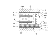
- an adhesion reinforcing layer is formed on the front surface 5af of the pressure detection element 5a, the rear surface 3r of the pressure receiving ring block portion 3, the rear surface 5ar of the pressure detection element 5a, and the front surface 6f of the support ring block portion 6. If the bonding layer C is coated with the inner layer Ci that becomes the diffusion layer, the intermediate layer Cm that becomes the diffusion prevention layer, and the outer layer Ce that becomes the diffusion layer, three parts of different materials, that is, the pressure receiving ring block portion 3, the pressure detection element 5a,. The support ring block portion 6 can be reliably bonded by the interposition of the bonding layers C.
- a predetermined thickness is applied to the rear surface 3r of the pressure-receiving ring block portion 3, the front surface 6f of the support ring block portion 6, the front surface 5af of the pressure detection element 5a, or the rear surface 5ar of the pressure detection element 5a.
- the alignment adjustment layer 14 for the pressure detection elements 5a using the melt-type bonding layer having the length Ls is provided, the rear surface 3r of the pressure receiving ring block portion 3, the front surface 6f of the support ring block portion 6, and further the alignment adjustment layer 14 Can be used to easily perform accurate alignment adjustment for each pressure detecting element 5a. Therefore, even when at least one pressure detection element 5a is used, variations in dimensions and angles can be absorbed and detection accuracy can be further increased.
- a connector portion 16 for connecting the electrode 4 and the lead 15 is provided in a portion of the one electrode 4 where the pressure detection element 5a ... does not exist. If the compressed spring 17 interposed between the electrodes 4 is provided, the lead 15 can be reliably connected to the electrode 4 and a highly reliable connection can be made.
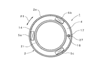
- FIG. 1 is a cross-sectional plan view taken along line AA in FIG.
- FIG. 1 is an enlarged view of a portion including a pressure detection element in FIG.
- FIG. 1 is an enlarged view of a portion including a connector portion in FIG.
- FIG. 1 is a cross-sectional plan view taken along line AA in FIG.
- FIG. 6 is a cross-sectional plan view corresponding to the line AA in FIG. 1 in a cylinder internal pressure sensor according to another modified embodiment of the present invention;
- FIG. 6 is a cross-sectional plan view corresponding to the line AA in FIG. 1 in a cylinder internal pressure sensor according to another modified embodiment of the present invention;
- SYMBOLS 1 Engine cylinder internal pressure sensor
- 2 Housing unit
- 2e Outer cylinder part
- 2i Inner cylinder part
- 2es Elastic part
- 2is Elastic part
- 3 Pressure receiving ring block part
- 3f Front surface of pressure receiving ring block part
- 3r rear surface of pressure-receiving ring block portion
- 4 one electrode portion, 5a, 5b, 5c ...: pressure detection element, 5af ...: front surface of pressure detection device, 5ar ...: rear surface of pressure detection device
- 6 support ring Block part
- 6f Front surface of support ring block part
- 7 The other electrode, 10a ...: Spacer, 10as ...: Spacer, 10at: Spacer, 11e: Bent part (or curved part), 11i: Bent part (or curved part) ), 12: pressure-receiving ring body, 13: insulating block, 14: alignment adjustment layer, 15: lead, 16: connector, 17: spring, Ec
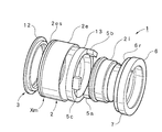
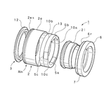
- FIG. 1 shows a configuration of a main part of the cylinder internal pressure sensor 1.
- a housing unit 2 includes an outer cylinder part 2e having a large diameter and an inner cylinder part 2i having a small diameter.
- the outer tube portion 2e and the inner tube portion 2i are integrally formed of an alloy material having excellent heat resistance, and elastic portions 2es and 2is having elasticity in the axial direction Fs are provided in the intermediate portion Xm in the axial direction Fs, respectively.
- the intermediate portion Xm is selected at a position closer to the front of the housing unit 2, preferably a position about several mm from the front end of the housing unit 2.
- the lower side is the front. Further, as shown in FIG.
- the elastic portions 2es and 2is are formed by bent portions 11e and 11i, respectively. That is, the elastic part 2es of the outer cylinder part 2e is formed by a bent part 11e in which the outer peripheral surface of the intermediate part Xm is bulged in the central direction, and the outer peripheral surface is surrounded by a groove having a trapezoidal (rectangular) cross section.
- the elastic portion 2is of the inner cylindrical portion 2i is formed by a bent portion 11i that bulges the inner peripheral surface of the intermediate portion Xm in the radial direction, and has a cross section on the inner peripheral surface.
- a concave groove having a trapezoidal (rectangular) shape is provided in a ring shape along the circumferential direction Ff.
- the outer cylinder part 2e and the inner cylinder part 2i are formed thin from the intermediate part Xm to the front end, and at least the intermediate part Xm has elasticity (spring property) in the axial direction Fs. Accordingly, constricted (bellows-like) elastic portions 2es and 2is are provided in the intermediate portion Xm of the housing unit 2. As described above, if the elastic portions 2es and 2is are provided by forming the bent portions 11e and 11i at the intermediate portion Xm of the outer cylinder portion 2e and the inner cylinder portion 2i, a part of the outer cylinder portion 2e and the inner cylinder portion 2i is provided. Therefore, there is an advantage that it can be implemented in an easy and optimum form in manufacturing.
- the pressure-receiving ring block portion 3 includes a pressure-receiving ring main body portion 12 disposed on the front side and an insulating block portion 13 that contacts the pressure-receiving ring main body portion 12 by being disposed on the rear side.
- the front surface of the pressure receiving ring body portion 12 becomes the front surface 3f of the pressure receiving ring block portion 3, and the front surface 3f becomes a pressure receiving surface that receives the internal pressure Pc.
- the pressure receiving ring main body 12 is integrally formed in a ring shape with an alloy material having excellent heat resistance, and the cross section is formed into a T shape with a wide portion and a narrow portion as shown in FIG. And the wide part in the pressure receiving ring main-body part 12 accommodates so that between the outer cylinder part 2e and the inner cylinder part 2i located ahead of the intermediate part Xm of the housing unit 2 may be accommodated, and the inner peripheral surface of the outer cylinder part 2e In addition, the outer peripheral surface of the inner cylinder portion 2i is hermetically fixed by welding portions 21 and 22 using laser welding or the like so that the combustion gas in the combustion chamber Rb does not enter the cylinder internal pressure sensor 1. At this time, the narrow portion of the pressure-receiving ring main body 12 is brought behind the elastic portions 2e and 2i through the elastic portions 2e and 2i.
- the insulating block 13 is integrally formed in a ring shape with a rigid insulating material and has a rectangular cross section. Therefore, the rear surface of the insulating block portion 13 becomes the rear surface 3r of the pressure receiving ring block portion 3. Further, one electrode portion 4 is provided on the rear surface 3 r of the pressure receiving ring block portion 3.
- the rear surface 3r of the pressure-receiving ring block portion 3, that is, the rear surface of the insulating block portion 13 is an inner layer Ci using Ti (titanium) serving as an adhesion strengthening layer and a diffusion prevention layer, as shown in FIG.
- An intermediate layer Cm using Pt (platinum) and an outer layer Ce using Au (gold) as a diffusion layer are coated, and on the bonding layer C, Au—Sn (gold-tin) is coated.
- An alignment adjustment layer 14 is formed by coating as a melt-type bonding layer having a predetermined thickness Ls.
- the alignment adjustment layer 14 has an alignment adjustment function that absorbs variations in dimensions and angles of three pressure detection elements 5a, which will be described later, and also serves as one electrode portion 4 of the pressure detection elements 5a. Therefore, the thickness Ls of the alignment adjustment layer 14 is selected to be a dimension capable of absorbing variations such as dimensions and angles of the three (at least one) pressure detection elements 5a.
- each layer Ci, Cm, Ce may be composed of a single element or an alloy containing a single element.
- the alignment adjustment layer 14 serving as a melt-type bonding layer includes other metals having eutectic phenomena such as Ag—Cu—Sn, Au—Ge, Au—Pd, Ag—Pd, Ag—Sn, and Cu—Sb. (Alloy) can be used. Each of these layers may be used as solder or brazing material. Therefore, the alignment adjustment layer 14 serving as the melt-type bonding layer and the outer layer Ce serving as the diffusion layer need to be combined. For example, when Au—Sn is used for the alignment adjustment layer 14, Au or Sn is used as the outer layer Ce.
- the material of the diffusion layer (outer layer Ce) needs to be aligned with the alignment adjustment layer 14, for example, Sn needs to be used, and Ag or Pd is used for the alignment adjustment layer 14. It is necessary to select a single material or a composite material among the constituent materials.
- Each pressure detecting element 5a is excellent in heat resistance and is a single crystal material having a spontaneous polarization without a Curie point that can obtain stable piezoelectric conversion characteristics even in a wide temperature range, specifically, LTG (La 3 Ta 0.5 Ga 5.5 O 14 ), LTGA (La 3 Ta 0.5 Ga 4.8 Al 0.2 O 14 ), LGS (La 3 Ga 5 SiO 14 ) and other single crystal materials such as LNG, LGSA, LNGA, CAAS, CTGS Use to make.
- LTG La 3 Ta 0.5 Ga 5.5 O 14
- LTGA La 3 Ta 0.5 Ga 4.8 Al 0.2 O 14
- LGS La 3 Ga 5 SiO 14
- other single crystal materials such as LNG, LGSA, LNGA, CAAS, CTGS Use to make.
- Each pressure detecting element 5a is sandwiched between the insulating block 13 described above and a support ring block 6 described later, and the front and rear surfaces are the rear surface of the insulating block 13 (alignment adjusting layer 14).
- the inner layer Ci, the intermediate layer Cm, and the outer layer Ce is coated.
- the alignment adjustment layer 14 provided on the rear surface 3r of the insulating block portion 13 before the heat treatment is directed upward.
- the three pressure detecting elements 5a, 5b, 5c are placed on the alignment adjustment layer 14 at equal intervals as shown in FIG.
- the front surface 6f of the support ring block 6 is applied to the rear surface 5ar (upper surface) of each pressure detection element 5a, and pressure is applied from above so that a uniform force is applied to each pressure detection element 5a.
- heating is performed in a reflow continuous furnace set to a predetermined temperature environment. As a result, as shown in FIG.
- the upper surface is in surface contact with the front surface 6f of the support ring block portion 6 respectively. That is, alignment adjustment is performed in which the alignment adjustment layer 14 absorbs variations such as dimensions and angles of the pressure detection elements 5a, 5b, and 5c.
- the bonding layers C provided on the front surfaces 5af of the pressure detecting elements 5a are welded to the alignment adjusting layer 14 and the bonding layers C provided on the rear surfaces 5ar of the pressure detecting elements 5a. Are welded to the bonding layer C provided on the front surface 6f of the support ring block portion 6.
- the insulating block portion 13, the pressure detecting elements 5a, and the support ring block portion 6 are integrally bonded. That is, the alignment adjustment step and the assembly step are performed together (simultaneously).
- the front end portion of the support ring block portion 6 is accommodated between the outer cylindrical portion 2e and the rear end portion of the inner cylindrical portion 2i, and a welded portion is formed on the inner peripheral surface of the outer cylindrical portion 2e and the outer peripheral surface of the inner cylindrical portion 2i. It fixes with 23,24.
- the support ring block portion 6 closes the rear end between the outer cylindrical portion 2e and the inner cylindrical portion 2i as shown in FIG.
- the front surface 6f of the ring block portion 6 serves as a support surface that supports the pressure detection elements 5a, 5b, and 5c. Further, the support ring block portion 6 also serves as the other electrode 7 (ground) of each pressure detection element 5a, 5b, 5c.
- the alignment adjustment layer 14 for the pressure detecting elements 5a using a melt-type bonding layer such as Au—Sn having a predetermined thickness Ls is provided on the rear surface 3r of the pressure receiving ring block portion 3, the pressure receiving ring block portion
- the alignment adjustment layer 14 for the pressure detecting elements 5a using a melt-type bonding layer such as Au—Sn having a predetermined thickness Ls is provided on the rear surface 3r of the pressure receiving ring block portion 3, the pressure receiving ring block portion
- the pressure receiving ring block portion By using the rear surface 3r 3 and the front surface 6f of the support ring block 6 and the alignment adjustment layer 14, it is possible to easily perform accurate alignment adjustment for each pressure detection element 5a. Therefore, even when three (at least one) pressure detection elements 5a are used, variations in dimensions and angles can be absorbed to further improve detection accuracy.
- the alignment adjustment layer 14 also functions as one electrode portion 4 provided on the rear surface 3r of the pressure receiving ring block portion 3. Therefore, the lead (shield cable) 14 led out is connected to the solidified alignment adjustment layer 14 (electrode 4). In this case, the electrode 4 and the lead 14 are connected via the connector portion 16.
- FIG. 4 shows an enlarged connection structure between the lead 15 and the electrode 4. The lead 15 introduced from the outside penetrates the support ring block portion 6 and the tip thereof faces the electrode 4. At this time, the lead 15 penetrating the support ring block portion 6 is held by the caulking pipe 25 and the insulating pipe 26 as shown in FIG.
- the spring holding terminal 27 of the connector portion 16 to which the tip of the lead 15 is connected is attached to the tip of the insulating pipe 26. As shown in FIG. 2, the spring holding terminal 27 is arranged in a space between the support ring block portion 6 and the insulating block portion 13 where the pressure detection elements 5 a. Then, one end of the compressed spring 17 is attached to the spring holding terminal 27, and the other end of the spring 17 is pressed against the upper surface of the electrode 4. Therefore, if such a connector part 16 is provided, the lead 15 can be reliably connected to the electrode 4 and a highly reliable connection can be made.
- the cylinder internal pressure sensor 1 is in contact with the one electrode portion 4 provided on the rear surface 3r of the pressure receiving ring block portion 3 whose front surface 3f is a pressure receiving surface, and is equally spaced along the circumferential direction Ff.
- the manufacturing (processing) of the pressure detection elements 5a is facilitated, and the yield and mass productivity are improved. This can contribute to improvement and further cost reduction, and is less likely to cause defects such as cracks, thereby contributing to improved reliability.
- the cylinder internal pressure sensor 1 is entirely covered with a cylindrical (ring-shaped) housing unit 2 or the like, and therefore, from a severe temperature environment or vibration environment when detecting the combustion pressure of the engine,
- the entire detection structure such as the pressure detection elements 5a... And the electrodes 4 and 7 is effectively protected, and stable mounting and stable operation with respect to the cylinder Ec are ensured. Therefore, as shown by a phantom line in FIG. 1, it can easily be mounted on the outer peripheral surface Mas of the tip of the injector Ma that faces the combustion chamber Rb of an engine such as an automobile and injects fuel into the cylinder Ec.
- the cylinder internal pressure sensor 1 can be assembled together with the injector Ma as a part of the injector Ma. That is, it is not necessary to form a separate through-hole at a predetermined position of the cylinder Ec and to attach it independently to this through-hole with a high airtight structure.
- the pressure-receiving ring main body portion 12 constituting the pressure-receiving ring block portion 3 is supported by the elastic portions 2es and 2is having elasticity in the axial direction Fs, so that the displacement of the pressure-receiving ring main body portion 12 by the internal pressure Pc ( Pressure) is stably (equally) and reliably transmitted to each of the pressure detecting elements 5a through the elastic parts 2es and 2is that expand and contract, and highly accurate pressure detection is performed.
- the pressure detection elements 5a, 5b, and 5c are aligned by the alignment adjustment layer 14, as illustrated, even when three pressure detection elements 5a are used, the dimensions and angles are increased. The detection accuracy is further improved by absorbing the variation.
- the number of pressure detecting elements 5a to be used is changed. 2 exemplifies the case where three pressure detecting elements 5a... Are used, the modified embodiment shown in FIG. 9 has six pressure detecting elements 5a, 5b, 5c, 5d, 5e, By using 5f, they are arranged at equal intervals along the circumferential direction Ff.
- the pressure detection elements 5a it is possible to use the pressure detection elements 5a.
- the remaining pressure detection elements can be configured as dummy having the same size. Included in the quantity.
- the use of the cylinder internal pressure sensor 1, that is, the functional component provided with the cylinder internal pressure sensor 1 is changed.
- the embodiment shown in FIG. 1 exemplifies the case where the injector Ma that injects fuel into the cylinder Ec is mounted.
- the modified embodiment shown in FIG. 10 shows the tip of the spark plug Mb that ignites the fuel in the cylinder Ec.
- wears with a part outer peripheral surface Mbs is shown.
- the shape of the cylinder internal pressure sensor 1 with respect to the outer peripheral surface Mbs of the tip end portion of the spark plug Mb is different, the shape of the inner cylinder portion 2i of the housing unit 2 is changed to match the shape of the spark plug Mb to be mounted. Just do it.
- the cylinder internal pressure sensor 1 can be easily attached to various functional parts such as the injector Ma and the spark plug Mb, and the highly versatile cylinder internal pressure sensor 1 can be obtained.
- the modified embodiment shown in FIGS. 11 to 13 is a modification of the mounting form of the pressure detecting elements 5a, and as shown in FIG. 12, the rear surface 3r of the pressure receiving ring block part 3, that is, the insulating block part 13
- the spacers 10a along the circumferential direction Ff are arranged at portions other than the pressure detection elements 5a ... in contact with the rear surface portion (including the alignment adjustment layer 14). If such spacers 10a ... are arranged, the space between the pressure detection elements 5a ... can be filled with the spacers 10a ..., 10as ..., 10at as shown in FIG. As a result, the alignment adjustment can be performed accurately and easily, and can be performed reliably and stably.
- the illustration shows a case where three spacers 10a, 10b, 10c formed of a ceramic material are used. Further, the width of each spacer 10a... Is made substantially equal to the width of the pressure receiving ring block portion 3, and the length in the axial direction Fs is selected corresponding to the length in the axial direction Fs of the pressure detecting elements 5a. In this case, the length in the axial direction Fs is preferably matched with the length in the axial direction Fs of the pressure detection elements 5a, but it is not always necessary to match, and the thickness of the alignment adjustment layer 14 and the spacer 10a. It can be changed depending on the material.
- the thickness of the spacer 10a is slightly thinner than the thickness (0.9 [mm]) of the pressure detection element 5a.
- the thickness (0.89 [mm]) was selected.
- the material of the spacers 10a is not limited to a rigid body, and a material having a certain degree of elasticity may be used. Therefore, the thickness of the spacers 10a may be larger than the thickness of the pressure detection elements 5a if necessary.
- symbol 10bh shows the penetration hole for making the spring holding terminal 27 and the spring 17 penetrate.
- the pressure detecting elements 5a and the spacers 10a are alternately arranged along the circumferential direction Ff of the pressure receiving ring block portion 3. By arranging in this way, it is possible to implement in the most desirable form from the viewpoint of balancing the stress when assisting the alignment adjustment and stabilizing the adjustment action. It is desirable that the pressure detection elements 5a and the spacers 10a are alternately arranged. However, it is not always necessary to arrange the pressure detection elements 5a and the spacers 10a, and the spacers 10a are present between the pressure detection elements 5a as necessary. It may be a form that does not.
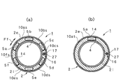
- FIG. 14 (a) and 14 (b) uses the same spacers 10as ..., 10at as the spacers 10a ... shown in FIG. 11, but the number of pressure detection elements 5a ... is changed.
- FIG. 14 (a) uses six pressure detection elements 5a, 5b, 5c, 5d, 5e, and 5f, is arranged at equal intervals along the circumferential direction Ff, and has six spacers 10as, 10bs, 10cs, and 10ds. , 10es, and 10fs are arranged between the pressure detection elements 5a in the same manner as in FIG. Therefore, each spacer 10as can be manufactured in the same manner as the spacer 10a, except that the length in the circumferential direction Ff is different.
- FIG. 14 (a) uses six pressure detection elements 5a, 5b, 5c, 5d, 5e, and 5f, is arranged at equal intervals along the circumferential direction Ff, and has six spacers 10as, 10bs, 10cs
- FIG. 14B shows a case where a single pressure detecting element 5a is used and arranged at a predetermined position in the circumferential direction Ff.
- a single spacer 10at having an overall shape C-shaped it can be implemented in the same manner as in FIG.
- the spacer 10at even one pressure detection element 5a can be implemented. Therefore, by using the spacers 10a,..., 10at shown in FIGS. 11 to 14, in addition to the effects described above, the mechanical strength when the pressure detection elements 5a are assembled can be improved. Further, it is possible to contribute to cost reduction accompanying reduction in the number of pressure detection elements 5a.
- FIG. 9 to FIG. 14 the same parts as those in FIG. 1 to FIG. 8 are given the same reference numerals to clarify the configuration, and detailed description thereof is omitted.
- the elastic portions 2es and 2is are provided by forming the bent portions 11e and 11i
- the elastic portions 2es and 2is may be formed by a curved portion such as a semicircular shape or a plurality of bent portions such as a bellows shape. .. (Or curved portion) 11e..., 11i.
- the injector Ma and the ignition plug Mb were applied as a functional component was shown, it is also possible to combine with other sensors (functional components), such as a temperature sensor.
- the pressure receiving ring block portion 3 is configured by combining the pressure receiving ring main body portion 12 and the insulating block portion 13, it may be an integral type.
- the alignment adjustment layer 14 for adjusting the alignment with respect to each pressure detecting element 5a is provided on the rear surface 3r of the pressure receiving ring block portion 3 is illustrated. You may provide in the front surface 6f of the support ring block part 6 instead of 3r. Moreover, although the case where the alignment adjustment layer 14 is provided on the upper surface of the bonding layer C is shown, when the bonding layer C is not provided, the rear surface 3r of the pressure receiving ring block portion 3 or the front surface 6f of the support ring block portion 6 is shown. You may provide directly.
- the alignment adjustment layer 14 is preferably provided on the rear surface 3r of the pressure receiving ring block portion 3 or the front surface 6f of the support ring block portion 6, but the front surface 5af of the pressure detection elements 5a ... or the rear surface 5ar of the pressure detection elements 5a ... It does not exclude the case where it is provided in....
- the alignment adjusting layer 14 is not necessarily provided when the pressure detecting elements 5a, which can ignore variations in dimensions and angles due to improvement in processing accuracy, are used.
- the structure for connecting one electrode 4 and the lead 15 is not limited to the illustrated configuration using the spring 17, and any other connection is possible as long as the electrode 4 and the lead 15 can be connected. It does not exclude the structure.
- the spark plug Mb includes various spark plugs such as a spark plug and a glow plug, and functional parts Ma and Mb facing the combustion chamber Rb of the engine are attached to the cylinder Ec as illustrated. In addition to the case, the case of attaching to the piston is also included.
- the cylinder internal pressure sensor according to the present invention can be used when detecting internal pressure of a cylinder constituting an internal combustion engine in various other applications including an internal combustion engine represented by an automobile engine.
Landscapes
- Engineering & Computer Science (AREA)
- Chemical & Material Sciences (AREA)
- Combustion & Propulsion (AREA)
- Physics & Mathematics (AREA)
- General Physics & Mathematics (AREA)
- Mechanical Engineering (AREA)
- General Engineering & Computer Science (AREA)
- Measuring Fluid Pressure (AREA)
Abstract
軸方向Fsの中間部Xmに軸方向Fsの弾性を有する弾性部位2es,2isを形成してなる外筒部2e及び内筒部2iからなるハウジングユニット2と、弾性部位2es,2isの前方に位置する外筒部2eと内筒部2i間に気密に固定し、かつ当該弾性部位2e,2iを通して弾性部位2e,2iの後方に臨ませるとともに、前面3fが受圧面となる受圧リングブロック部3と、この受圧リングブロック部3の後面3rに設けた一方の電極部4に接し、かつ受圧リングブロック部3から内圧Pcが付与されるとともに、周方向Ffの所定位置に配した少なくとも一つ以上の圧力検出素子5a,5b,5c…と、外筒部2eと内筒部2i間に固定し、かつ前面6fが圧力検出素子5a…を支持する支持面になるとともに、他方の電極7を兼ねた支持リングブロック部6とを備える。
Description
本発明は、シリンダの内圧を検出する際に用いて好適なリング形に構成したエンジン用シリンダ内圧センサに関する。
一般に、エンジンの燃焼室に臨ませることによりシリンダの内圧(燃焼圧)を検出するエンジン用シリンダ内圧センサは知られているが、この種のシリンダ内圧センサは、シリンダの所定位置に形成した貫通孔に高い気密性構造により独立して取付ける必要がある。このため、シリンダ内圧センサをリング形に構成し、エンジンに付設する他の機能部品である点火プラグの先端部外周面に一体に取付可能に構成して、当該点火プラグと一緒にシリンダに取付けできるようにしたシリンダ内圧センサも知られている。
従来、このようなリング形に構成したシリンダ内圧センサとしては、特許文献1で開示される燃焼圧力センサ,特許文献2で開示される圧力センサ及び特許文献3で開示される圧力センサ内蔵スパークプラグが知られている。
特許文献1の燃焼圧センサは、中心電極の周囲に形成された絶縁体と、側方電極と電気的に接続され、絶縁体の周囲に形成された座金部材と、を有する点火プラグに内蔵されたる燃焼圧力センサにおいて、絶縁体及び座金部材の間であり、かつ中心電極および側方電極の間の点火ギャップ近傍に設置されたニオブ酸リチウムからなる圧電素子と、を備えて構成されている。また、特許文献2の圧力センサは、スパークプラグのガスケットの替わりに装着孔に共締めされる圧力センサであって、この圧力センサは、ハウジングの取付け面がシリンダヘッドに圧接され、ハウジングには放熱フィンが固着された構成を備えている。さらに、特許文献3の圧力センサ内蔵スパークプラグは、内燃機関に取付けた際に、内燃機関に設けられたプラグ取付面と対向する座部と、この座部に内蔵されており、座部の内壁面の周方向に所定の間隔ごとに複数の圧電素子が保持された収容部材と、この収容部材に対応した平板形状に形成されているとともに、切り込みを入れた部分を上方へ折り曲げた端子が形成されており、その折り曲げにより形成された切り欠き部が圧電素子と重ならない状態で収容部材の上面に設けられた電極板と、この電極板に対応した平板形状に形成されているとともに、切り欠き部が形成されており、その切り欠き部から電極板の端子を上方へ突出させた状態で電極板の上面に設けられた絶縁板と、この絶縁板の切り欠き部から突出した端子に接続されており、圧電素子の出力を取り出す取出部材と、を備えている。
しかし、上述したリング形に構成した従来のエンジン用シリンダ内圧センサは、次のような問題点があった。
即ち、この種のシリンダ内圧センサは、エンジンの燃焼圧を検出するため、使用する圧力検出素子には、高い耐熱性を有し、かつ高温環境下でも良好な圧電変換特性を有する単結晶材料が望ましい。反面、単結晶材料は脆性が大きいため、単結晶材料をカッティングして、上述した特許文献1及び2のようなリング形の圧力検出素子を切り出すには、高度の加工技術が要求されるなど、製造は容易でない。結局、歩留まりの低下及び量産性の低下を招くとともに、コストアップ要因としても無視できない。しかも、全体を細いリング形に形成する必要があることから、振動の大きいエンジンに付設した場合には割れ等の不具合を生じる虞れがあり、必ずしも信頼性の高い圧力検出素子とはいえない。
一方、特許文献3は、圧力検出素子を直方体形のチップ体として形成するとともに、複数のチップ体をリング形に配列して構成するため、上述したリング形に一体形成する場合における製造(加工)上の問題は生じないが、反面、各チップ体における寸法や角度上のバラツキがシリンダ内圧センサの特性(性能)に直接影響し、これにより、検出精度の低下及び製品バラツキを生じやすい難点がある。
しかも、いずれの場合も、エンジンの燃焼圧を検出するものであるため、圧力検出素子や電極等の内部構造を、厳しい温度環境や振動環境から、できるだけ保護する必要があるが、全体の検出構造において必ずしも十分とはいえず、シリンダ内圧センサの安定な装着及び安定な作動を確保する観点からは更なる改善の余地があった。
本発明は、このような背景技術に存在する課題を解決したエンジン用シリンダ内圧センサの提供を目的とするものである。
本発明は、上述した課題を解決するため、エンジンの燃焼室Rbに臨ませた機能部品Ma,Mbの先端部外周面Mas,Mbsに装着することによりシリンダEcの内圧Pcを検出するリング形に構成したエンジン用シリンダ内圧センサ1を構成するに際して、軸方向Fsの中間部Xmに軸方向Fsの弾性を有する弾性部位2es,2isを形成してなる外筒部2e及び内筒部2iからなるハウジングユニット2と、弾性部位2es,2isの前方に位置する外筒部2eと内筒部2i間に気密に固定し、かつ当該弾性部位2e,2iを通して弾性部位2e,2iの後方に臨ませるとともに、前面3fが受圧面となる受圧リングブロック部3と、この受圧リングブロック部3の後面3rに設けた一方の電極部4に接し、かつ受圧リングブロック部3から内圧Pcが付与されるとともに、周方向Ffの所定位置に配した少なくとも一つ以上の圧力検出素子5a,5b,5c…と、外筒部2eと内筒部2i間に固定し、かつ前面6fが圧力検出素子5a…を支持する支持面になるとともに、他方の電極7を兼ねた支持リングブロック部6とを備えることを特徴とする。
この場合、発明の好適な態様により、受圧リングブロック部3の後面部位に接し、かつ圧力検出素子5a…を除く部位には、周方向Ffに沿った一又は二以上のスペーサ10a…,10as…,10atを配置することが望ましい。この際、より好ましくは、圧力検出素子5a…とスペーサ10a…,10as…,10atは受圧リングブロック部3の周方向Ffに沿って交互に配置するとともに、スペーサ10a…,10as…,10atの軸方向Fsの長さは、圧力検出素子5a…の軸方向Fsの長さに対応させて選定する。一方、弾性部位2es,2isは、外筒部2e及び内筒部2iの中間部Xmに屈曲部(又は湾曲部)11e,11iを形成して設けることができる。また、受圧リングブロック部3は、前側に配した受圧リング本体部12と、後側に配することにより当該受圧リング本体部12に当接する絶縁ブロック部13により構成することができるとともに、圧力検出素子5a…には、単結晶材料を用いることができる。
他方、圧力検出素子5a…の前面5af…,受圧リングブロック部3の後面3r,圧力検出素子5a…の後面5ar…,支持リングブロック部6の前面6fには、密着強化層となる内層Ci,拡散防止層となる中間層Cm,拡散層となる外層Ceによる接合層Cをコーティングすることができる。また、受圧リングブロック部3の後面3r,支持リングブロック部6の前面6f,圧力検出素子5a…の前面5af…又は圧力検出素子5a…の後面5ar…には、所定の厚さLsを有する溶融系接合層を用いた圧力検出素子5a…に対するアライメント調整層14を設けることができる。さらに、一方の電極4における圧力検出素子5a…が存在しない部位にはリード15を接続するコネクタ部16を設けることができ、この際、コネクタ部16には、リード15と一方の電極4間に介在する圧縮したスプリング17を設けることができる。なお、機能部品(Ma,Mb)には、シリンダEc内に燃料を噴射するインジェクタMa,或いはシリンダEc内の燃料に点火する点火プラグMbを適用することができる。
このような本発明に係るエンジン用シリンダ内圧センサ1によれば、次のような顕著な効果を奏する。
(1) 軸方向Fsの中間部Xmに軸方向Fsの弾性を有する弾性部位2es,2isを形成してなる外筒部2e及び内筒部2iからなるハウジングユニット2に対して、この外筒部2eと内筒部2i間に、前側から、受圧リングブロック部3,一方の電極4,少なくとも一つ以上の圧力検出素子5a…及び他方の電極7を兼ねる支持リングブロック部6を順次配して構成したため、受圧リングブロック部3で受けた圧力は、伸縮する弾性部位2es,2isにより、各圧力検出素子5a…に対して、安定(均等)かつ確実に伝達することができ、精度の高い圧力検出を行うことができる。
(2) 前面3fが受圧面となる受圧リングブロック部3の後面3rに設けた一方の電極部4に接するとともに、周方向Ffに沿って等間隔に配した少なくとも一つ以上の圧力検出素子5a…を用いたため、圧力検出素子5a…として、脆性の大きい単結晶材料を使用し、かつエンジンの燃焼室Rbに臨ませた機能部品Ma,Mbの先端部外周面Mas,Mbsに装着するリング形のシリンダ内圧センサ1を構成する場合でも、圧力検出素子5a…の製造(加工)が容易となり、歩留まり及び量産性の向上、更にはコストダウンに寄与できるとともに、割れ等の不具合が発生しにくく、信頼性向上にも寄与できる。
(3) 円筒形(リング形)のハウジングユニット2により、圧力検出素子5a…や電極4及び7等の検出構造の全体を覆うため、エンジンの燃焼圧を検出する際の厳しい温度環境や振動環境から検出構造の全体を有効に保護し、シリンダEcに対する安定な装着及び安定な作動を確保できるとともに、インジェクタMaや点火プラグMb等の各種機能部品に対して容易に装着可能となり、汎用性の高いシリンダ内圧センサ1を得ることができる。
(4) 好適な態様により、受圧リングブロック部3の後面部位に接し、かつ圧力検出素子5a…を除く部位に、周方向Ffに沿った一又は二以上のスペーサ10a…,10as…,10atを配置するようにすれば、圧力検出素子5a…間の空間をスペーサ10a…,10as…,10atにより埋めることができるため、組立時における圧力検出素子5a…のアライメント調整を補助し、アライメント調整を正確かつ容易に行うことができるとともに、確実かつ安定に行うことができる。加えて、機械的強度の向上を図れるとともに、圧力検出素子5a…の数量削減に伴うコスト低減にも寄与することができる。
(5) 好適な態様により、圧力検出素子5a…とスペーサ10a…,10as…,10atを受圧リングブロック部3の周方向Ffに沿って交互に配置するようにすれば、アライメント調整を補助する際における応力バランスを図り、かつ調整作用の安定化を図る観点から最も望ましい形態により実施できる。
(6) 好適な態様により、スペーサ10a…,10as…,10atの軸方向Fsの長さを、圧力検出素子5a…の軸方向Fsの長さに対応させて選定すれば、スペーサ10a…,10as…,10atを配置することによる作用(機能)を最も効果的に発揮させることができる。
(7) 好適な態様により、弾性部位2es,2isを、外筒部2e及び内筒部2iの中間部Xmに屈曲部(又は湾曲部)11e,11iを形成して設ければ、外筒部2e及び内筒部2iの一部により一体形成できるため、製造上、容易かつ最適な形態により実施できる。
(8) 好適な態様により、圧力検出素子5a…の前面5af…,受圧リングブロック部3の後面3r,圧力検出素子5a…の後面5ar…,支持リングブロック部6の前面6fに、密着強化層となる内層Ci,拡散防止層となる中間層Cm,拡散層となる外層Ceによる接合層Cをコーティングすれば、材質の異なる三つの部品、即ち、受圧リングブロック部3,圧力検出素子5a…及び支持リングブロック部6を、接合層C…の介在により確実に接合することができる。
(9) 好適な態様により、受圧リングブロック部3の後面3r,支持リングブロック部6の前面6f,圧力検出素子5a…の前面5af…又は圧力検出素子5a…の後面5ar…に、所定の厚さLsを有する溶融系接合層を用いた圧力検出素子5a…に対するアライメント調整層14を設ければ、受圧リングブロック部3の後面3r及び支持リングブロック部6の前面6f、更にはアライメント調整層14を利用して、各圧力検出素子5a…に対する的確なアライメント調整を容易に行うことができる。したがって、少なくとも一つ以上の圧力検出素子5a…を用いる場合であっても、寸法や角度上のバラツキを吸収して検出精度をより高めることができる。
(10) 好適な態様により、一方の電極4における圧力検出素子5a…が存在しない部位に当該電極4とリード15を接続するコネクタ部16を設けるとともに、この際、コネクタ部16に、リード15と電極4間に介在する圧縮したスプリング17を設ければ、電極4に対するリード15の接続を確実に行うことができるとともに、信頼性の高い接続を行うことができる。
1:エンジン用シリンダ内圧センサ,2:ハウジングユニット,2e:外筒部,2i:内筒部,2es:弾性部位,2is:弾性部位,3:受圧リングブロック部,3f:受圧リングブロック部の前面,3r:受圧リングブロック部の後面,4:一方の電極部,5a,5b,5c…:圧力検出素子,5af…:圧力検出素子の前面,5ar…:圧力検出素子の後面,6:支持リングブロック部,6f:支持リングブロック部の前面,7:他方の電極,10a…:スペーサ,10as…:スペーサ,10at:スペーサ,11e:屈曲部(又は湾曲部),11i:屈曲部(又は湾曲部),12:受圧リング本体部,13:絶縁ブロック部,14:アライメント調整層,15:リード,16:コネクタ部,17:スプリング,Ec:エンジンのシリンダ,Ma:機能部品(インジェクタ),Mb:機能部品(点火プラグ),Mas:機能部品の先端部外周面,Mbs:機能部品の先端部外周面,Pc:内圧,Fs:軸方向,Ff:周方向,Xm:中間部,Ci:内層,Cm:中間層,Ce:外層,Ls:所定の厚さ,エンジンの燃焼室Rb
次に、本発明に係る最良実施形態を挙げ、図面に基づき詳細に説明する。
まず、本実施形態に係るシリンダ内圧センサ1の構成について、図1~図8を参照して説明する。
図1は、シリンダ内圧センサ1の要部の構成を示す。2はハウジングユニットであり、径の大きい外筒部2eと径の小さい内筒部2iを備える。外筒部2e及び内筒部2iは、それぞれ耐熱性に優れた合金素材等により一体形成し、軸方向Fsの中間部Xmには軸方向Fsの弾性を有する弾性部位2es及び2isをそれぞれ設ける。中間部Xmは、図1に示すように、ハウジングユニット2の前寄り位置、望ましくはハウジングユニット2の前端から数〔mm〕程度後方の位置を選定する。なお、図1は下方が前方となる。また、弾性部位2es,2isは、図3に示すように、それぞれ屈曲部11e,11iにより形成する。即ち、外筒部2eの弾性部位2esは、中間部Xmの外周面を中心方向に膨出させた屈曲部11eにより形成し、外周面に、断面が台形(矩形)状となる凹溝を周方向Ffに沿ってリング状に設けるとともに、内筒部2iの弾性部位2isは、中間部Xmの内周面を放射方向に膨出させた屈曲部11iにより形成し、内周面に、断面が台形(矩形)状となる凹溝を周方向Ffに沿ってリング状に設ける。この場合、外筒部2e及び内筒部2iは、中間部Xmから前端までを薄肉形成し、少なくとも中間部Xmには軸方向Fsの弾性(バネ性)を持たせる。これにより、ハウジングユニット2の中間部Xmに、括れ状(ベローズ状)の弾性部位2es,2isが設けられる。このように、弾性部位2es,2isを、外筒部2e及び内筒部2iの中間部Xmに屈曲部11e,11iを形成して設ければ、外筒部2e及び内筒部2iの一部により一体形成できるため、製造上、容易かつ最適な形態により実施できる利点がある。
一方、弾性部位2es,2isの前方に位置する外筒部2eと内筒部2i間に気密に固定し、かつ当該弾性部位2e,2iを通して弾性部位2e,2iの後方に至らせる受圧リングブロック部3を設ける。受圧リングブロック部3は、前側に配した受圧リング本体部12と、後側に配することにより当該受圧リング本体部12に当接する絶縁ブロック部13により構成する。これにより、受圧リング本体部12の前面は、受圧リングブロック部3の前面3fとなり、この前面3fが内圧Pcを受ける受圧面となる。
受圧リング本体部12は、全体を耐熱性に優れた合金素材等によりリング状に一体形成するとともに、断面を、図3に示すように、広幅部分と狭幅部分によりT形に形成する。そして、受圧リング本体部12における広幅部分は、ハウジングユニット2の中間部Xmよりも前方に位置する外筒部2eと内筒部2i間を埋めるように収容し、外筒部2eの内周面及び内筒部2iの外周面にレーザ溶接等を用いた溶接部21,22により気密に固定し、燃焼室Rb内の燃焼ガスがシリンダ内圧センサ1の内部に入り込まないようにする。この際、受圧リング本体部12における狭幅部分は、弾性部位2eと2i間を通して当該弾性部位2e,2iの後方に至らせる。
また、絶縁ブロック部13は、剛性を有する絶縁素材によりリング状に一体形成し、断面は矩形となる。したがって、絶縁ブロック部13の後面は、受圧リングブロック部3の後面3rとなる。さらに、受圧リングブロック部3の後面3rには、一方の電極部4を設ける。この場合、受圧リングブロック部3の後面3r、即ち、絶縁ブロック部13の後面には、図7に示すように、密着強化層となるTi(チタン)を用いた内層Ci,拡散防止層となるPt(白金)を用いた中間層Cm,拡散層となるAu(金)を用いた外層Ceによる接合層Cをコーティングするとともに、この接合層Cの上には、Au-Sn(金-錫)を用いた所定の厚さLsを有する溶融系接合層となるアライメント調整層14をコーティングにより設ける。このアライメント調整層14は、後述する三つの圧力検出素子5a…の寸法及び角度等のバラツキを吸収するアライメント調整機能を備えるとともに、圧力検出素子5a…の一方の電極部4を兼用する。したがって、アライメント調整層14の厚さLsは、三つ(少なくとも一つ以上)の圧力検出素子5a…の寸法及び角度等のバラツキを吸収できる寸法を選定する。
なお、密着強化層となる内層Ciには、その他、Ni,Cr,Zr,In,Bi,Y等を、拡散防止層となる中間層Cmには、その他、Cu,Sn,Ni,Fe,Cr,V,Ti等を、拡散層となる外層Ceには、その他、Ag,Pd,Sn,Ge,Cu等を、それぞれ選択して用いることができる。この場合、各層Ci,Cm,Ceは、単一元素で構成してもよいし、単一元素を含む合金により構成してもよい。また、溶融系接合層となるアライメント調整層14には、その他、Ag-Cu-Sn,Au-Ge,Au-Pd,Ag-Pd,Ag-Sn,Cu-Sb等の共晶現象を有する金属(合金)を用いることができる。これらの各層は、ハンダとして用いてもよいし、ろう材として用いてもよい。したがって、溶融系接合層となるアライメント調整層14と拡散層となる外層Ceは、組合わせが必要であり、例えば、アライメント調整層14にAu-Snを用いた場合には、外層CeにAu又はSnを用いる必要があり、アライメント調整層14にAg-Pdを用いた場合には、外層CeにAg又はPdを用いる必要があるなど、拡散層(外層Ce)の材料は、アライメント調整層14を構成する材料のうちの単一材料又は複合材料に選定する必要がある。
他方、5a,5b,5cは、三つの圧力検出素子(圧電素子)を示す。各圧力検出素子5a…は、耐熱性に優れ、広い温度範囲においても安定した圧電変換特性が得られるキュリー点の無い自発分極を有する単結晶材料、具体的には、LTG(La3Ta0.5Ga5.5O14),LTGA(La3Ta0.5Ga4.8Al0.2O14),LGS(La3Ga5SiO14)の単結晶材料をはじめ、LNG,LGSA,LNGA,CAAS,CTGS等の単結晶材料を用いて製作する。また、各圧力検出素子5a…は、前述した絶縁ブロック部13と後述する支持リングブロック部6間にサンドイッチ状に挟まれ、かつ前面及び後面を、絶縁ブロック部13の後面(アライメント調整層14)及び支持リングブロック部6の前面にそれぞれ接合するため、各圧力検出素子5a…の前面5af…及び後面5ar…には、図7に示すように、上述した内層Ci,中間層Cm,外層Ceからなる接合層Cをそれぞれコーティングする。
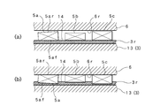
そして、圧力検出素子5a,5b,5cの組付けを行う際には、図8(a)に示すように、加熱処理前の絶縁ブロック部13の後面3rに設けたアライメント調整層14を、上向きとなるようにセットし、このアライメント調整層14の上に、三つの圧力検出素子5a,5b,5cを、図2に示すように等間隔で載置する。次いで、各圧力検出素子5a…の後面5ar(上面)に、支持リングブロック部6の前面6fを当て、上から各圧力検出素子5a…に対して均一の力が付加されるように加圧するとともに、所定の温度環境に設定したリフロー連続炉で加熱を行う。これにより、図8(b)に示すように、適度に溶融したアライメント調整層14に、各圧力検出素子5a…の前面5af…(下面)が入り込み、各圧力検出素子5a…の後面5ar…(上面)はそれぞれ支持リングブロック部6の前面6fに面接触する。即ち、各圧力検出素子5a,5b,5cの寸法及び角度等のバラツキがアライメント調整層14により吸収されるアライメント調整が行われる。また、この際、同時に、各圧力検出素子5a…の前面5af…に設けた接合層C…がアライメント調整層14に溶着するとともに、各圧力検出素子5a…の後面5ar…に設けた接合層C…が支持リングブロック部6の前面6fに設けた接合層Cに溶着する。
したがって、アライメント調整層14及び接合層C…が固化した後は、絶縁ブロック部13,各圧力検出素子5a…及び支持リングブロック部6が一体に接合される。即ち、アライメント調整工程と組付工程が一緒(同時)に行われる。この際、支持リングブロック部6の前端部は、外筒部2eと内筒部2iの後端部間に収容し、外筒部2eの内周面及び内筒部2iの外周面に溶接部23,24により固定する。以上の組付工程により、支持リングブロック部6は、図1に示すように、外筒部2eと内筒部2i間の後端を閉塞するとともに、ハウジングユニット2の後端に固定された支持リングブロック部6の前面6fは各圧力検出素子5a,5b,5cを支持する支持面となる。また、支持リングブロック部6は、各圧力検出素子5a,5b,5cの他方の電極7(グランド)を兼ねている。
このように、圧力検出素子5a…の前面5af…,受圧リングブロック部3の後面3r,圧力検出素子5a…の後面5ar…,支持リングブロック部6の前面6fに、内層Ci,中間層Cm,外層Ceからなる接合層Cをコーティングすれば、材質の異なる三つの部品、即ち、受圧リングブロック部3,圧力検出素子5a…及び支持リングブロック部6を、接合層C…の介在により確実に接合できる。また、受圧リングブロック部3の後面3rに、所定の厚さLsを有するAu-Sn等の溶融系接合層を用いた圧力検出素子5a…に対するアライメント調整層14を設ければ、受圧リングブロック部3の後面3r及び支持リングブロック部6の前面6f、更にはアライメント調整層14を利用して、各圧力検出素子5a…に対する的確なアライメント調整を容易に行うことができる。したがって、三つ(少なくとも一つ以上)の圧力検出素子5a…を用いる場合であっても、寸法や角度上のバラツキを吸収して検出精度をより高めることができる。
一方、アライメント調整層14は、受圧リングブロック部3の後面3rに設けた一方の電極部4としても機能する。したがって、固化したアライメント調整層14(電極4)に対して外部に導出するリード(シールドケーブル)14を接続する。この場合、電極4とリード14はコネクタ部16を介して接続する。図4は、リード15と電極4の接続構造を拡大して示す。外部から導入したリード15は、支持リングブロック部6を貫通させ、先端を電極4に臨ませる。この際、支持リングブロック部6を貫通するリード15は、図4に示すように、カシメ用パイプ25と絶縁パイプ26により保持される。また、絶縁パイプ26の先端には、リード15の先端を接続したコネクタ部16のスプリング保持端子27を取付ける。このスプリング保持端子27は、図2に示すように、圧力検出素子5a…が存在しない支持リングブロック部6と絶縁ブロック部13間の空間に配し、電極4に臨ませる。そして、圧縮状態にしたスプリング17の一端をスプリング保持端子27に装着し、かつスプリング17の他端を電極4の上面に圧接させる。したがって、このようなコネクタ部16を設ければ、電極4に対するリード15の接続を確実に行うことができるとともに、信頼性の高い接続を行うことができる。
このように、本実施形態に係るシリンダ内圧センサ1は、前面3fが受圧面となる受圧リングブロック部3の後面3rに設けた一方の電極部4に接するとともに、周方向Ffに沿って等間隔に配した三つ(少なくとも一つ以上)の圧力検出素子5a…を用いた基本構造を有するため、圧力検出素子5a…として、脆性の大きい単結晶材料を使用し、かつ後述するようにシリンダEcに付設されるインジュクタMaの先端部外周面Masに装着するリング形のシリンダ内圧センサ1を構成する場合であっても、圧力検出素子5a…の製造(加工)が容易となり、歩留まり及び量産性の向上、更にはコストダウンに寄与できるとともに、割れ等の不具合が発生しにくく、信頼性向上にも寄与できる。
次に、本実施形態に係るシリンダ内圧センサ1の使用方法及び動作(機能)について、図1~図8を参照して説明する。
まず、シリンダ内圧センサ1は、図6に示すように、全体が円筒形(リング形)のハウジングユニット2等により覆われるため、エンジンの燃焼圧を検出する際の厳しい温度環境や振動環境から、圧力検出素子5a…や電極4及び7等の検出構造の全体が有効に保護されるとともに、シリンダEcに対する安定な装着及び安定な作動が確保される。したがって、図1に仮想線で示すように、自動車等のエンジンの燃焼室Rbに臨み、かつシリンダEcの内部に燃料を噴射するインジェクタMaの先端部外周面Masに容易に装着可能となる。即ち、インジェクタMaをシリンダEcに組付ける際に、いわばインジェクタMaの一部として、シリンダ内圧センサ1も一緒にインジェクタMaに組付けることができる。即ち、シリンダEcの所定位置に別途の貫通孔を形成し、この貫通孔に高い気密性構造により独立して取付けることは不要となる。
一方、シリンダEcにおける内圧Pcの検出時には、内圧Pcが、受圧リングブロック部3の受圧面(前面3f)に付加されるため、この内圧Pcは、受圧リング本体部12及び絶縁ブロック部13を介して各圧力検出素子5a,5b,5cに作用する。この際、受圧リングブロック部3を構成する受圧リング本体部12は、軸方向Fsの弾性を有する伸縮性の弾性部位2es,2isにより支持されるため、内圧Pcによる受圧リング本体部12の変位(圧力)は、伸縮する弾性部位2es,2isにより、各圧力検出素子5a…に、安定(均等)かつ確実に伝達され、精度の高い圧力検出が行われる。加えて、各圧力検出素子5a,5b,5cは、アライメント調整層14によりアライメント調整されているため、例示のように、三つの圧力検出素子5a…を用いる場合であっても、寸法や角度上のバラツキを吸収して検出精度がより高められる。
次に、本発明の変更実施形態に係るシリンダ内圧センサ1について、図9~図14を参照して説明する。
図9に示す変更実施形態は、使用する圧力検出素子5a…の数量を変更したものである。前述した図2に示した実施形態は三つの圧力検出素子5a…を用いた場合を例示したが、図9に示す変更実施形態は、六つの圧力検出素子5a,5b,5c,5d,5e,5fを用いることにより、周方向Ffに沿って等間隔に配したものである。このように、本発明に係るシリンダ内圧センサ1では、少なくとも一つ以上の任意の数量による圧力検出素子5a…を使用することができる。なお、偶数の場合、二つの圧力検出素子5a…を使用し、残りの圧力検出素子を大きさを一致させたダミーとして構成することも可能であるが、このようなダミーも圧力検出素子5a…の数量に含まれる。
図10に示す変更実施形態は、シリンダ内圧センサ1の用途、即ち、シリンダ内圧センサ1を付設する機能部品を変更したものである。図1に示した実施形態は、シリンダEc内に燃料を噴射するインジェクタMaに装着した場合を例示したが、図10に示す変更実施形態は、シリンダEc内の燃料に点火する点火プラグMbの先端部外周面Mbsに装着する場合を示す。なお、点火プラグMbの先端部外周面Mbsに対するシリンダ内圧センサ1の形状が異なる場合には、ハウジングユニット2の内筒部2iの形状を変更し、装着対象となる点火プラグMbの形状にマッチングさせればよい。このように、シリンダ内圧センサ1は、インジェクタMaや点火プラグMb等の各種機能部品に対して容易に装着可能となり、汎用性の高いシリンダ内圧センサ1を得ることができる。
図11~図13に示す変更実施形態は、圧力検出素子5a…の取付形態を変更したものであり、図12に示すように、受圧リングブロック部3の後面3r、即ち、絶縁ブロック部13の後面部位(アライメント調整層14を含む)に接し、かつ圧力検出素子5a…を除く部位に、周方向Ffに沿ったスペーサ10a…を配置したものである。このようなスペーサ10a…を配置すれば、図13に示すように、圧力検出素子5a…間の空間をスペーサ10a…,10as…,10atにより埋めることができるため、組立時の圧力検出素子5a…のアライメント調整を補助し、アライメント調整を正確かつ容易に行うことができるとともに、確実かつ安定に行うことができる。
例示はセラミックス素材により形成した三つのスペーサ10a,10b,10cを用いた場合を示す。また、各スペーサ10a…の幅は受圧リングブロック部3の幅にほぼ一致させるとともに、軸方向Fsの長さは、圧力検出素子5a…の軸方向Fsの長さに対応させて選定した。この場合、軸方向Fsの長さは、圧力検出素子5a…の軸方向Fsの長さに一致させることが望ましいが、必ずしも一致させることを要せず、アライメント調整層14の厚さやスペーサ10a…の素材により変更可能である。例示するスペーサ10a…の素材には、剛性体(セラミックス素材)を用いたため、スペーサ10a…の厚さは、圧力検出素子5a…の厚さ(0.9〔mm〕)に対して僅かに薄い厚さ(0.89〔mm〕)を選定した。なお、スペーサ10a…の素材は、剛性体に限定されるものではなく、ある程度の弾性を有する素材を利用してもよい。したがって、スペーサ10a…の厚さは、必要により圧力検出素子5a…の厚さよりも厚くなってもよい。このように、スペーサ10a…の軸方向Fsの長さを、圧力検出素子5a…の軸方向Fsの長さに対応させて選定すれば、スペーサ10a…を配置することによる作用(機能)を最も効果的に発揮させることができる。その他、図11において、符号10bhは、スプリング保持端子27及びスプリング17を挿通させるための挿通孔を示す。
さらに、圧力検出素子5a…とスペーサ10a…は受圧リングブロック部3の周方向Ffに沿って交互に配置する。このように配置することにより、アライメント調整を補助する際における応力バランスを図り、かつ調整作用の安定化を図る観点から最も望ましい形態により実施できる。なお、圧力検出素子5a…とスペーサ10a…は交互に配置することが望ましいが、必ずしも交互に配置することを要せず、必要に応じて圧力検出素子5a…の相互間にスペーサ10a…が存在しない形態であってもよい。
図14(a),(b)に示す変更実施形態は、図11に示したスペーサ10a…と同様のスペーサ10as…,10atを用いるも、圧力検出素子5a…の数量を変更したものである。図14(a)は、六つの圧力検出素子5a,5b,5c,5d,5e,5fを使用し、周方向Ffに沿って等間隔に配するとともに、六つのスペーサ10as,10bs,10cs,10ds,10es,10fsを、図11と同様に各圧力検出素子5a…の相互間に配置した。したがって、各スペーサ10as…は、周方向Ffにおける長さが異なる点を除いてスペーサ10a…と同様に製作できる。一方、図14(b)は、単一の圧力検出素子5aを使用し、周方向Ffの所定位置に配した場合を示す。この場合であっても、全体の形状をC形に形成した単一のスペーサ10atを使用すれば、図11と同様に実施できる。このように、スペーサ10atを使用すれば、一つの圧力検出素子5aであっても実施可能となる。よって、このような図11~図14に示すスペーサ10a…,10as…,10atを使用すれば、前述した効果に加え、圧力検出素子5a…を組付けた際の機械的強度の向上を図れるとともに、圧力検出素子5a…の数量削減に伴うコスト低減にも寄与できる。その他、図9~図14において、図1~図8と同一の部分には同一符号を付し、その構成を明確にするとともに、詳細な説明は省略する。
以上、最良実施形態及び変更実施形態について詳細に説明したが、本発明は、このような実施形態に限定されるものではなく、細部の構成,形状,素材,数量,手法等において、本発明の精神を逸脱しない範囲で、任意に変更,追加,削除することができる。
例えば、弾性部位2es,2isは、屈曲部11e,11iを形成して設けた場合を示したが、半円形等の湾曲部により形成してもよいし、或いは蛇腹形のように、複数の屈曲部(又は湾曲部)11e…,11i…の組合わせにより構成してもよい。また、機能部品として、インジェクタMaと点火プラグMbを適用した場合を示したが、その他、温度センサ等の他のセンサ(機能部品)と組合わせることも可能である。一方、受圧リングブロック部3は、受圧リング本体部12と絶縁ブロック部13の組合わせにより構成した場合を示したが一体タイプであってもよい。さらに、圧力検出素子5a…は、単結晶材料を用いることが望ましいが、ピエゾ素子等の検出原理の異なる他の圧力検出素子の使用を排除するものではない。他方、受圧リングブロック部3の後面3rに、各圧力検出素子5a…に対するアライメント調整を行うアライメント調整層14を設けた場合を例示したが、このアライメント調整層14は、受圧リングブロック部3の後面3rの代わりに支持リングブロック部6の前面6fに設けてもよい。また、アライメント調整層14は、接合層Cの上面に設けた場合を示したが、接合層Cを設けない場合には、受圧リングブロック部3の後面3r又は支持リングブロック部6の前面6fに直接設けてもよい。さらに、アライメント調整層14は、受圧リングブロック部3の後面3r又は支持リングブロック部6の前面6fに設けるのが望ましいが、圧力検出素子5a…の前面5af…又は圧力検出素子5a…の後面5ar…に設ける場合を排除するものではない。なお、このアライメント調整層14は、加工精度の向上により寸法及び角度等に対するバラツキが無視できる圧力検出素子5a…を用いる場合には必ずしも設けることを要しない。他方、一方の電極4とリード15を接続する構造は、スプリング17を用いた例示の構成に限定されるものではなく、電極4とリード15を接続することができるものであれば、他の接続構造を排除するものではない。また、点火プラグMbには、スパークプラグ及びグロープラグ等の各種点火プラグが含まれるとともに、エンジンの燃焼室Rbに臨ませた機能部品Ma,Mbとは、例示のように、シリンダEcに付設する場合の他、ピストンに付設する場合も含まれる。
本発明に係るシリンダ内圧センサは、自動車のエンジンで代表される内燃機関をはじめ、他の各種用途における内燃機関を構成するシリンダの内圧を検出する際に利用することができる。
Claims (13)
- エンジンの燃焼室に臨ませた機能部品の先端部外周面に装着することにより前記シリンダの内圧を検出するリング形に構成したエンジン用シリンダ内圧センサにおいて、軸方向の中間部に軸方向の弾性を有する弾性部位を形成してなる外筒部及び内筒部からなるハウジングユニットと、前記弾性部位の前方に位置する前記外筒部と前記内筒部間に気密に固定し、かつ当該弾性部位を通して前記弾性部位より後方に臨ませるとともに、前面が受圧面となる受圧リングブロック部と、この受圧リングブロック部の後面に設けた一方の電極部に接し、かつ前記受圧リングブロック部から内圧が付与されるとともに、周方向の所定位置に配した少なくとも一つ以上の圧力検出素子と、前記外筒部と前記内筒部間に固定し、かつ前面が前記圧力検出素子を支持する支持面になるとともに、他方の電極を兼ねた支持リングブロック部とを備えることを特徴とするエンジン用シリンダ内圧センサ。
- 前記受圧リングブロック部の後面部位に接し、かつ前記圧力検出素子を除く部位には、周方向に沿った一又は二以上のスペーサを配置することを特徴とする請求項1記載のエンジン用シリンダ内圧センサ。
- 前記圧力検出素子と前記スペーサは前記受圧リングブロック部の周方向に沿って交互に配置することを特徴とする請求項2記載のエンジン用シリンダ内圧センサ。
- 前記スペーサの軸方向長さは、前記圧力検出素子の軸方向長さに対応させて選定することを特徴とする請求項2又は3記載のエンジン用シリンダ内圧センサ。
- 前記弾性部位は、前記外筒部及び前記内筒部の中間部に、屈曲部又は湾曲部を形成することにより設けることを特徴とする請求項1~4にいずれかに記載のエンジン用シリンダ内圧センサ。
- 前記受圧リングブロック部は、前側に配した受圧リング本体部と、後側に配することにより当該受圧リング本体部に当接する絶縁ブロック部により構成することを特徴とする請求項1~5のいずれかに記載のエンジン用シリンダ内圧センサ。
- 前記圧力検出素子は、単結晶材料を用いることを特徴とする請求項1~6のいずれかに記載のエンジン用シリンダ内圧センサ。
- 前記圧力検出素子の前面,前記受圧リングブロック部の後面,前記圧力検出素子の後面,前記支持リングブロック部の前面には、密着強化層となる内層,拡散防止層となる中間層,拡散層となる外層による接合層をコーティングしてなることを特徴とする請求項1~7のいずれかに記載のエンジン用シリンダ内圧センサ。
- 前記受圧リングブロック部の後面,前記支持リングブロック部の前面,前記圧力検出素子の前面又は前記圧力検出素子の後面には、所定の厚さを有する溶融系接合層を用いた前記圧力検出素子に対するアライメント調整層を設けることを特徴とする請求項1~8のいずれかに記載のエンジン用シリンダ内圧センサ。
- 前記一方の電極における前記圧力検出素子が存在しない部位にリードを接続するコネクタ部を備えることを特徴とする請求項1~9のいずれかに記載のエンジン用シリンダ内圧センサ。
- 前記コネクタ部は、前記リードと前記一方の電極間に介在する圧縮したスプリングを備えることを特徴とする請求項10記載のエンジン用シリンダ内圧センサ。
- 前記機能部品は、前記シリンダ内に燃料を噴射するインジェクタであることを特徴とする請求項1~11のいずれかに記載のエンジン用シリンダ内圧センサ。
- 前記機能部品は、前記シリンダ内の燃料に点火する点火プラグであることを特徴とする請求項1~11のいずれかに記載のエンジン用シリンダ内圧センサ。
Priority Applications (5)
| Application Number | Priority Date | Filing Date | Title |
|---|---|---|---|
| US14/004,282 US8915125B2 (en) | 2011-03-31 | 2012-03-29 | Cylinder internal-pressure sensor for engine |
| CN201280016410.4A CN103460005B (zh) | 2011-03-31 | 2012-03-29 | 发动机用气缸内压传感器 |
| EP12765630.4A EP2693185B1 (en) | 2011-03-31 | 2012-03-29 | Cylinder internal-pressure sensor for engine |
| JP2013507195A JP5981910B2 (ja) | 2011-03-31 | 2012-03-29 | エンジン用シリンダ内圧センサ |
| HK14104301.0A HK1191092A1 (zh) | 2011-03-31 | 2014-05-06 | 發動機用氣缸內壓傳感器 |
Applications Claiming Priority (2)
| Application Number | Priority Date | Filing Date | Title |
|---|---|---|---|
| PCT/JP2011/001976 WO2012131788A1 (ja) | 2011-03-31 | 2011-03-31 | エンジン用シリンダ内圧センサ |
| JPPCT/JP2011/001976 | 2011-03-31 |
Publications (1)
| Publication Number | Publication Date |
|---|---|
| WO2012132450A1 true WO2012132450A1 (ja) | 2012-10-04 |
Family
ID=46929637
Family Applications (2)
| Application Number | Title | Priority Date | Filing Date |
|---|---|---|---|
| PCT/JP2011/001976 WO2012131788A1 (ja) | 2011-03-31 | 2011-03-31 | エンジン用シリンダ内圧センサ |
| PCT/JP2012/002182 WO2012132450A1 (ja) | 2011-03-31 | 2012-03-29 | エンジン用シリンダ内圧センサ |
Family Applications Before (1)
| Application Number | Title | Priority Date | Filing Date |
|---|---|---|---|
| PCT/JP2011/001976 WO2012131788A1 (ja) | 2011-03-31 | 2011-03-31 | エンジン用シリンダ内圧センサ |
Country Status (6)
| Country | Link |
|---|---|
| US (1) | US8915125B2 (ja) |
| EP (1) | EP2693185B1 (ja) |
| JP (1) | JP5981910B2 (ja) |
| CN (1) | CN103460005B (ja) |
| HK (1) | HK1191092A1 (ja) |
| WO (2) | WO2012131788A1 (ja) |
Cited By (3)
| Publication number | Priority date | Publication date | Assignee | Title |
|---|---|---|---|---|
| JP2014163881A (ja) * | 2013-02-27 | 2014-09-08 | Citizen Finetech Miyota Co Ltd | 圧力検出装置 |
| JP2015190333A (ja) * | 2014-03-27 | 2015-11-02 | Tdk株式会社 | 燃焼圧センサ |
| WO2020138016A1 (ja) * | 2018-12-28 | 2020-07-02 | 川崎重工業株式会社 | 船舶 |
Families Citing this family (3)
| Publication number | Priority date | Publication date | Assignee | Title |
|---|---|---|---|---|
| JP6008087B2 (ja) * | 2012-03-27 | 2016-10-19 | 株式会社ケーヒン | 筒内圧センサ付き燃料噴射弁 |
| JP6066767B2 (ja) * | 2013-02-28 | 2017-01-25 | シチズンファインデバイス株式会社 | 内燃機関用燃焼圧センサ及びその製造方法。 |
| DE112015001644T8 (de) * | 2014-04-04 | 2017-01-19 | Citizen Finedevice Co., Ltd. | Zylinderinnendruckerfassungsvorrichtung |
Citations (6)
| Publication number | Priority date | Publication date | Assignee | Title |
|---|---|---|---|---|
| JPS58144247U (ja) * | 1982-03-24 | 1983-09-28 | 日産自動車株式会社 | 内燃機関の筒内圧力センサ取付装置 |
| JPS59211835A (ja) * | 1983-05-18 | 1984-11-30 | Nissan Motor Co Ltd | 筒内圧検出装置 |
| JPS63235841A (ja) * | 1987-03-25 | 1988-09-30 | Ngk Spark Plug Co Ltd | ガスケツト型圧力センサ− |
| JPH0434327A (ja) | 1990-05-30 | 1992-02-05 | Nissan Motor Co Ltd | 燃焼圧力センサ |
| JPH1194675A (ja) | 1997-09-19 | 1999-04-09 | Ngk Spark Plug Co Ltd | 圧力センサ |
| JP2000277233A (ja) | 1999-03-24 | 2000-10-06 | Ngk Spark Plug Co Ltd | 圧力センサ内蔵スパークプラグ |
Family Cites Families (16)
| Publication number | Priority date | Publication date | Assignee | Title |
|---|---|---|---|---|
| JPH06307953A (ja) * | 1993-04-27 | 1994-11-04 | Hitachi Ltd | 物理量検出装置 |
| US5831263A (en) * | 1994-04-26 | 1998-11-03 | Hitachi, Ltd. | In-cylinder pressure sensing apparatus for multi-cylinder engine |
| US7152478B2 (en) * | 2000-07-20 | 2006-12-26 | Entegris, Inc. | Sensor usable in ultra pure and highly corrosive environments |
| US6617764B2 (en) * | 2000-09-13 | 2003-09-09 | University Of Dayton | High temperature piezoelectric sensor |
| JP4620882B2 (ja) * | 2001-02-20 | 2011-01-26 | 日本特殊陶業株式会社 | 圧力センサ内蔵プラグ |
| US6701775B1 (en) * | 2002-02-15 | 2004-03-09 | Dana Corporation | Pressure sensor apparatus for measuring pressures including knock conditions in engine cylinders |
| US6739183B1 (en) * | 2002-02-15 | 2004-05-25 | Dana Corporation | Multiple-layer cylinder head gasket with integral pressure sensor apparatus for measuring pressures within engine cylinders |
| US7111505B2 (en) * | 2002-02-15 | 2006-09-26 | Dana Corporation | Multi-layer steel cylinder head gasket with integrated pressure sensor |
| MXPA04007987A (es) * | 2002-02-15 | 2005-06-17 | Dana Corp | Aparato para la medicion de presiones en cilindros de motor. |
| JP2004045184A (ja) * | 2002-07-11 | 2004-02-12 | Denso Corp | 半導体力学量センサ |
| US7197937B2 (en) * | 2005-01-26 | 2007-04-03 | Sensata Technologies, Inc. | Hermetic pressure sensing device |
| JP4903165B2 (ja) * | 2005-02-24 | 2012-03-28 | キストラー ホールディング アクチエンゲゼルシャフト | 電気絶縁皮膜によって保持された圧電式力センサ用部品又は圧電式圧力センサ用部品 |
| GB0609519D0 (en) * | 2006-05-12 | 2006-06-21 | Delphi Tech Inc | Fuel injector |
| JP5547201B2 (ja) * | 2008-10-03 | 2014-07-09 | フェデラル−モーグル コーポレイション | 圧縮センサガスケットおよび構成方法 |
| CN102459967A (zh) * | 2009-06-01 | 2012-05-16 | 费德罗-莫格尔公司 | 压缩传感器垫圈组件及构造方法 |
| JP2011022071A (ja) * | 2009-07-17 | 2011-02-03 | Ngk Spark Plug Co Ltd | 燃焼圧センサ |
-
2011
- 2011-03-31 WO PCT/JP2011/001976 patent/WO2012131788A1/ja active Application Filing
-
2012
- 2012-03-29 EP EP12765630.4A patent/EP2693185B1/en active Active
- 2012-03-29 CN CN201280016410.4A patent/CN103460005B/zh not_active Expired - Fee Related
- 2012-03-29 WO PCT/JP2012/002182 patent/WO2012132450A1/ja active Application Filing
- 2012-03-29 US US14/004,282 patent/US8915125B2/en not_active Expired - Fee Related
- 2012-03-29 JP JP2013507195A patent/JP5981910B2/ja not_active Expired - Fee Related
-
2014
- 2014-05-06 HK HK14104301.0A patent/HK1191092A1/zh not_active IP Right Cessation
Patent Citations (6)
| Publication number | Priority date | Publication date | Assignee | Title |
|---|---|---|---|---|
| JPS58144247U (ja) * | 1982-03-24 | 1983-09-28 | 日産自動車株式会社 | 内燃機関の筒内圧力センサ取付装置 |
| JPS59211835A (ja) * | 1983-05-18 | 1984-11-30 | Nissan Motor Co Ltd | 筒内圧検出装置 |
| JPS63235841A (ja) * | 1987-03-25 | 1988-09-30 | Ngk Spark Plug Co Ltd | ガスケツト型圧力センサ− |
| JPH0434327A (ja) | 1990-05-30 | 1992-02-05 | Nissan Motor Co Ltd | 燃焼圧力センサ |
| JPH1194675A (ja) | 1997-09-19 | 1999-04-09 | Ngk Spark Plug Co Ltd | 圧力センサ |
| JP2000277233A (ja) | 1999-03-24 | 2000-10-06 | Ngk Spark Plug Co Ltd | 圧力センサ内蔵スパークプラグ |
Cited By (5)
| Publication number | Priority date | Publication date | Assignee | Title |
|---|---|---|---|---|
| JP2014163881A (ja) * | 2013-02-27 | 2014-09-08 | Citizen Finetech Miyota Co Ltd | 圧力検出装置 |
| JP2015190333A (ja) * | 2014-03-27 | 2015-11-02 | Tdk株式会社 | 燃焼圧センサ |
| WO2020138016A1 (ja) * | 2018-12-28 | 2020-07-02 | 川崎重工業株式会社 | 船舶 |
| JP2020104787A (ja) * | 2018-12-28 | 2020-07-09 | 川崎重工業株式会社 | 船舶 |
| JP7273508B2 (ja) | 2018-12-28 | 2023-05-15 | 川崎重工業株式会社 | 船舶 |
Also Published As
| Publication number | Publication date |
|---|---|
| US8915125B2 (en) | 2014-12-23 |
| EP2693185B1 (en) | 2019-07-31 |
| CN103460005A (zh) | 2013-12-18 |
| WO2012131788A1 (ja) | 2012-10-04 |
| CN103460005B (zh) | 2016-01-20 |
| JP5981910B2 (ja) | 2016-08-31 |
| US20140083388A1 (en) | 2014-03-27 |
| JPWO2012132450A1 (ja) | 2014-07-24 |
| EP2693185A4 (en) | 2015-01-14 |
| HK1191092A1 (zh) | 2014-07-18 |
| EP2693185A1 (en) | 2014-02-05 |
Similar Documents
| Publication | Publication Date | Title |
|---|---|---|
| JP5981910B2 (ja) | エンジン用シリンダ内圧センサ | |
| JP3885515B2 (ja) | 燃焼圧センサ付きグロープラグ | |
| US20060214541A1 (en) | Multilayer piezoelectric element, fuel injector having the piezoelectric element and piezoelectric element production method | |
| DK3124944T3 (en) | PIEZOELECTRIC PRESSURE SENSOR | |
| JP2014173995A (ja) | 圧力センサおよびその製造方法 | |
| JP3123799B2 (ja) | 圧力センサ | |
| US9368943B2 (en) | Spark plug having multi-layer sparking component attached to ground electrode | |
| US10330550B2 (en) | Piezoelectric pressure sensor | |
| JP6231984B2 (ja) | 燃焼圧センサ | |
| JP6286355B2 (ja) | 内燃機関用燃焼圧センサ付き機能部品ユニット | |
| JP6231987B2 (ja) | 圧力検出装置 | |
| JP2012042376A (ja) | 温度センサ | |
| JP2017032559A (ja) | 圧電型圧力センサ | |
| JPH09260024A (ja) | 圧力センサ内蔵スパークプラグ | |
| JP5519590B2 (ja) | 温度センサの製造方法及び温度センサ | |
| JP2020020635A (ja) | 圧力検出装置 | |
| JP6074288B2 (ja) | 圧力検出装置 | |
| JP2004257890A (ja) | ガスセンサ | |
| JP2018163082A (ja) | 圧力検出装置、内燃機関用部品 | |
| JP2013015396A (ja) | 温度センサ及び温度センサの製造方法 | |
| JPH06313746A (ja) | 圧力センサ | |
| JP2021056034A (ja) | ガスセンサ | |
| JP2020085865A (ja) | 圧力検出装置および圧力検出装置の製造方法 | |
| JP2018136286A (ja) | 燃焼圧センサ | |
| WO2004068097A1 (ja) | 圧力センサ |
Legal Events
| Date | Code | Title | Description |
|---|---|---|---|
| 121 | Ep: the epo has been informed by wipo that ep was designated in this application |
Ref document number: 12765630 Country of ref document: EP Kind code of ref document: A1 |
|
| ENP | Entry into the national phase |
Ref document number: 2013507195 Country of ref document: JP Kind code of ref document: A |
|
| WWE | Wipo information: entry into national phase |
Ref document number: 14004282 Country of ref document: US |
|
| NENP | Non-entry into the national phase |
Ref country code: DE |