WO2012132405A1 - 車載充電装置 - Google Patents
車載充電装置 Download PDFInfo
- Publication number
- WO2012132405A1 WO2012132405A1 PCT/JP2012/002109 JP2012002109W WO2012132405A1 WO 2012132405 A1 WO2012132405 A1 WO 2012132405A1 JP 2012002109 W JP2012002109 W JP 2012002109W WO 2012132405 A1 WO2012132405 A1 WO 2012132405A1
- Authority
- WO
- WIPO (PCT)
- Prior art keywords
- vehicle
- information
- vehicle information
- storage unit
- control unit
- Prior art date
- Legal status (The legal status is an assumption and is not a legal conclusion. Google has not performed a legal analysis and makes no representation as to the accuracy of the status listed.)
- Ceased
Links
Images


Classifications
-
- B—PERFORMING OPERATIONS; TRANSPORTING
- B60—VEHICLES IN GENERAL
- B60L—PROPULSION OF ELECTRICALLY-PROPELLED VEHICLES; SUPPLYING ELECTRIC POWER FOR AUXILIARY EQUIPMENT OF ELECTRICALLY-PROPELLED VEHICLES; ELECTRODYNAMIC BRAKE SYSTEMS FOR VEHICLES IN GENERAL; MAGNETIC SUSPENSION OR LEVITATION FOR VEHICLES; MONITORING OPERATING VARIABLES OF ELECTRICALLY-PROPELLED VEHICLES; ELECTRIC SAFETY DEVICES FOR ELECTRICALLY-PROPELLED VEHICLES
- B60L53/00—Methods of charging batteries, specially adapted for electric vehicles; Charging stations or on-board charging equipment therefor; Exchange of energy storage elements in electric vehicles
- B60L53/10—Methods of charging batteries, specially adapted for electric vehicles; Charging stations or on-board charging equipment therefor; Exchange of energy storage elements in electric vehicles characterised by the energy transfer between the charging station and the vehicle
- B60L53/14—Conductive energy transfer
-
- H—ELECTRICITY
- H02—GENERATION; CONVERSION OR DISTRIBUTION OF ELECTRIC POWER
- H02J—CIRCUIT ARRANGEMENTS OR SYSTEMS FOR SUPPLYING OR DISTRIBUTING ELECTRIC POWER; SYSTEMS FOR STORING ELECTRIC ENERGY
- H02J7/00—Circuit arrangements for charging or depolarising batteries or for supplying loads from batteries
- H02J7/00047—Circuit arrangements for charging or depolarising batteries or for supplying loads from batteries with provisions for charging different types of batteries
-
- B—PERFORMING OPERATIONS; TRANSPORTING
- B60—VEHICLES IN GENERAL
- B60L—PROPULSION OF ELECTRICALLY-PROPELLED VEHICLES; SUPPLYING ELECTRIC POWER FOR AUXILIARY EQUIPMENT OF ELECTRICALLY-PROPELLED VEHICLES; ELECTRODYNAMIC BRAKE SYSTEMS FOR VEHICLES IN GENERAL; MAGNETIC SUSPENSION OR LEVITATION FOR VEHICLES; MONITORING OPERATING VARIABLES OF ELECTRICALLY-PROPELLED VEHICLES; ELECTRIC SAFETY DEVICES FOR ELECTRICALLY-PROPELLED VEHICLES
- B60L1/00—Supplying electric power to auxiliary equipment of vehicles
- B60L1/003—Supplying electric power to auxiliary equipment of vehicles to auxiliary motors, e.g. for pumps, compressors
-
- B—PERFORMING OPERATIONS; TRANSPORTING
- B60—VEHICLES IN GENERAL
- B60L—PROPULSION OF ELECTRICALLY-PROPELLED VEHICLES; SUPPLYING ELECTRIC POWER FOR AUXILIARY EQUIPMENT OF ELECTRICALLY-PROPELLED VEHICLES; ELECTRODYNAMIC BRAKE SYSTEMS FOR VEHICLES IN GENERAL; MAGNETIC SUSPENSION OR LEVITATION FOR VEHICLES; MONITORING OPERATING VARIABLES OF ELECTRICALLY-PROPELLED VEHICLES; ELECTRIC SAFETY DEVICES FOR ELECTRICALLY-PROPELLED VEHICLES
- B60L3/00—Electric devices on electrically-propelled vehicles for safety purposes; Monitoring operating variables, e.g. speed, deceleration or energy consumption
- B60L3/0023—Detecting, eliminating, remedying or compensating for drive train abnormalities, e.g. failures within the drive train
- B60L3/0069—Detecting, eliminating, remedying or compensating for drive train abnormalities, e.g. failures within the drive train relating to the isolation, e.g. ground fault or leak current
-
- B—PERFORMING OPERATIONS; TRANSPORTING
- B60—VEHICLES IN GENERAL
- B60L—PROPULSION OF ELECTRICALLY-PROPELLED VEHICLES; SUPPLYING ELECTRIC POWER FOR AUXILIARY EQUIPMENT OF ELECTRICALLY-PROPELLED VEHICLES; ELECTRODYNAMIC BRAKE SYSTEMS FOR VEHICLES IN GENERAL; MAGNETIC SUSPENSION OR LEVITATION FOR VEHICLES; MONITORING OPERATING VARIABLES OF ELECTRICALLY-PROPELLED VEHICLES; ELECTRIC SAFETY DEVICES FOR ELECTRICALLY-PROPELLED VEHICLES
- B60L3/00—Electric devices on electrically-propelled vehicles for safety purposes; Monitoring operating variables, e.g. speed, deceleration or energy consumption
- B60L3/04—Cutting off the power supply under fault conditions
-
- B—PERFORMING OPERATIONS; TRANSPORTING
- B60—VEHICLES IN GENERAL
- B60L—PROPULSION OF ELECTRICALLY-PROPELLED VEHICLES; SUPPLYING ELECTRIC POWER FOR AUXILIARY EQUIPMENT OF ELECTRICALLY-PROPELLED VEHICLES; ELECTRODYNAMIC BRAKE SYSTEMS FOR VEHICLES IN GENERAL; MAGNETIC SUSPENSION OR LEVITATION FOR VEHICLES; MONITORING OPERATING VARIABLES OF ELECTRICALLY-PROPELLED VEHICLES; ELECTRIC SAFETY DEVICES FOR ELECTRICALLY-PROPELLED VEHICLES
- B60L53/00—Methods of charging batteries, specially adapted for electric vehicles; Charging stations or on-board charging equipment therefor; Exchange of energy storage elements in electric vehicles
- B60L53/10—Methods of charging batteries, specially adapted for electric vehicles; Charging stations or on-board charging equipment therefor; Exchange of energy storage elements in electric vehicles characterised by the energy transfer between the charging station and the vehicle
- B60L53/14—Conductive energy transfer
- B60L53/16—Connectors, e.g. plugs or sockets, specially adapted for charging electric vehicles
-
- B—PERFORMING OPERATIONS; TRANSPORTING
- B60—VEHICLES IN GENERAL
- B60L—PROPULSION OF ELECTRICALLY-PROPELLED VEHICLES; SUPPLYING ELECTRIC POWER FOR AUXILIARY EQUIPMENT OF ELECTRICALLY-PROPELLED VEHICLES; ELECTRODYNAMIC BRAKE SYSTEMS FOR VEHICLES IN GENERAL; MAGNETIC SUSPENSION OR LEVITATION FOR VEHICLES; MONITORING OPERATING VARIABLES OF ELECTRICALLY-PROPELLED VEHICLES; ELECTRIC SAFETY DEVICES FOR ELECTRICALLY-PROPELLED VEHICLES
- B60L53/00—Methods of charging batteries, specially adapted for electric vehicles; Charging stations or on-board charging equipment therefor; Exchange of energy storage elements in electric vehicles
- B60L53/10—Methods of charging batteries, specially adapted for electric vehicles; Charging stations or on-board charging equipment therefor; Exchange of energy storage elements in electric vehicles characterised by the energy transfer between the charging station and the vehicle
- B60L53/14—Conductive energy transfer
- B60L53/18—Cables specially adapted for charging electric vehicles
-
- B—PERFORMING OPERATIONS; TRANSPORTING
- B60—VEHICLES IN GENERAL
- B60L—PROPULSION OF ELECTRICALLY-PROPELLED VEHICLES; SUPPLYING ELECTRIC POWER FOR AUXILIARY EQUIPMENT OF ELECTRICALLY-PROPELLED VEHICLES; ELECTRODYNAMIC BRAKE SYSTEMS FOR VEHICLES IN GENERAL; MAGNETIC SUSPENSION OR LEVITATION FOR VEHICLES; MONITORING OPERATING VARIABLES OF ELECTRICALLY-PROPELLED VEHICLES; ELECTRIC SAFETY DEVICES FOR ELECTRICALLY-PROPELLED VEHICLES
- B60L53/00—Methods of charging batteries, specially adapted for electric vehicles; Charging stations or on-board charging equipment therefor; Exchange of energy storage elements in electric vehicles
- B60L53/60—Monitoring or controlling charging stations
- B60L53/65—Monitoring or controlling charging stations involving identification of vehicles or their battery types
-
- H—ELECTRICITY
- H01—ELECTRIC ELEMENTS
- H01M—PROCESSES OR MEANS, e.g. BATTERIES, FOR THE DIRECT CONVERSION OF CHEMICAL ENERGY INTO ELECTRICAL ENERGY
- H01M10/00—Secondary cells; Manufacture thereof
- H01M10/42—Methods or arrangements for servicing or maintenance of secondary cells or secondary half-cells
- H01M10/44—Methods for charging or discharging
-
- H—ELECTRICITY
- H02—GENERATION; CONVERSION OR DISTRIBUTION OF ELECTRIC POWER
- H02J—CIRCUIT ARRANGEMENTS OR SYSTEMS FOR SUPPLYING OR DISTRIBUTING ELECTRIC POWER; SYSTEMS FOR STORING ELECTRIC ENERGY
- H02J13/00—Circuit arrangements for providing remote indication of network conditions, e.g. an instantaneous record of the open or closed condition of each circuitbreaker in the network; Circuit arrangements for providing remote control of switching means in a power distribution network, e.g. switching in and out of current consumers by using a pulse code signal carried by the network
- H02J13/00006—Circuit arrangements for providing remote indication of network conditions, e.g. an instantaneous record of the open or closed condition of each circuitbreaker in the network; Circuit arrangements for providing remote control of switching means in a power distribution network, e.g. switching in and out of current consumers by using a pulse code signal carried by the network characterised by information or instructions transport means between the monitoring, controlling or managing units and monitored, controlled or operated power network element or electrical equipment
- H02J13/00007—Circuit arrangements for providing remote indication of network conditions, e.g. an instantaneous record of the open or closed condition of each circuitbreaker in the network; Circuit arrangements for providing remote control of switching means in a power distribution network, e.g. switching in and out of current consumers by using a pulse code signal carried by the network characterised by information or instructions transport means between the monitoring, controlling or managing units and monitored, controlled or operated power network element or electrical equipment using the power network as support for the transmission
- H02J13/00009—Circuit arrangements for providing remote indication of network conditions, e.g. an instantaneous record of the open or closed condition of each circuitbreaker in the network; Circuit arrangements for providing remote control of switching means in a power distribution network, e.g. switching in and out of current consumers by using a pulse code signal carried by the network characterised by information or instructions transport means between the monitoring, controlling or managing units and monitored, controlled or operated power network element or electrical equipment using the power network as support for the transmission using pulsed signals
-
- H—ELECTRICITY
- H02—GENERATION; CONVERSION OR DISTRIBUTION OF ELECTRIC POWER
- H02J—CIRCUIT ARRANGEMENTS OR SYSTEMS FOR SUPPLYING OR DISTRIBUTING ELECTRIC POWER; SYSTEMS FOR STORING ELECTRIC ENERGY
- H02J7/00—Circuit arrangements for charging or depolarising batteries or for supplying loads from batteries
- H02J7/00032—Circuit arrangements for charging or depolarising batteries or for supplying loads from batteries characterised by data exchange
- H02J7/00036—Charger exchanging data with battery
-
- H—ELECTRICITY
- H02—GENERATION; CONVERSION OR DISTRIBUTION OF ELECTRIC POWER
- H02J—CIRCUIT ARRANGEMENTS OR SYSTEMS FOR SUPPLYING OR DISTRIBUTING ELECTRIC POWER; SYSTEMS FOR STORING ELECTRIC ENERGY
- H02J7/00—Circuit arrangements for charging or depolarising batteries or for supplying loads from batteries
- H02J7/0029—Circuit arrangements for charging or depolarising batteries or for supplying loads from batteries with safety or protection devices or circuits
- H02J7/0031—Circuit arrangements for charging or depolarising batteries or for supplying loads from batteries with safety or protection devices or circuits using battery or load disconnect circuits
-
- B—PERFORMING OPERATIONS; TRANSPORTING
- B60—VEHICLES IN GENERAL
- B60L—PROPULSION OF ELECTRICALLY-PROPELLED VEHICLES; SUPPLYING ELECTRIC POWER FOR AUXILIARY EQUIPMENT OF ELECTRICALLY-PROPELLED VEHICLES; ELECTRODYNAMIC BRAKE SYSTEMS FOR VEHICLES IN GENERAL; MAGNETIC SUSPENSION OR LEVITATION FOR VEHICLES; MONITORING OPERATING VARIABLES OF ELECTRICALLY-PROPELLED VEHICLES; ELECTRIC SAFETY DEVICES FOR ELECTRICALLY-PROPELLED VEHICLES
- B60L2210/00—Converter types
- B60L2210/30—AC to DC converters
-
- B—PERFORMING OPERATIONS; TRANSPORTING
- B60—VEHICLES IN GENERAL
- B60L—PROPULSION OF ELECTRICALLY-PROPELLED VEHICLES; SUPPLYING ELECTRIC POWER FOR AUXILIARY EQUIPMENT OF ELECTRICALLY-PROPELLED VEHICLES; ELECTRODYNAMIC BRAKE SYSTEMS FOR VEHICLES IN GENERAL; MAGNETIC SUSPENSION OR LEVITATION FOR VEHICLES; MONITORING OPERATING VARIABLES OF ELECTRICALLY-PROPELLED VEHICLES; ELECTRIC SAFETY DEVICES FOR ELECTRICALLY-PROPELLED VEHICLES
- B60L2240/00—Control parameters of input or output; Target parameters
- B60L2240/10—Vehicle control parameters
- B60L2240/34—Cabin temperature
-
- B—PERFORMING OPERATIONS; TRANSPORTING
- B60—VEHICLES IN GENERAL
- B60L—PROPULSION OF ELECTRICALLY-PROPELLED VEHICLES; SUPPLYING ELECTRIC POWER FOR AUXILIARY EQUIPMENT OF ELECTRICALLY-PROPELLED VEHICLES; ELECTRODYNAMIC BRAKE SYSTEMS FOR VEHICLES IN GENERAL; MAGNETIC SUSPENSION OR LEVITATION FOR VEHICLES; MONITORING OPERATING VARIABLES OF ELECTRICALLY-PROPELLED VEHICLES; ELECTRIC SAFETY DEVICES FOR ELECTRICALLY-PROPELLED VEHICLES
- B60L2240/00—Control parameters of input or output; Target parameters
- B60L2240/10—Vehicle control parameters
- B60L2240/36—Temperature of vehicle components or parts
-
- B—PERFORMING OPERATIONS; TRANSPORTING
- B60—VEHICLES IN GENERAL
- B60L—PROPULSION OF ELECTRICALLY-PROPELLED VEHICLES; SUPPLYING ELECTRIC POWER FOR AUXILIARY EQUIPMENT OF ELECTRICALLY-PROPELLED VEHICLES; ELECTRODYNAMIC BRAKE SYSTEMS FOR VEHICLES IN GENERAL; MAGNETIC SUSPENSION OR LEVITATION FOR VEHICLES; MONITORING OPERATING VARIABLES OF ELECTRICALLY-PROPELLED VEHICLES; ELECTRIC SAFETY DEVICES FOR ELECTRICALLY-PROPELLED VEHICLES
- B60L2270/00—Problem solutions or means not otherwise provided for
- B60L2270/10—Emission reduction
- B60L2270/14—Emission reduction of noise
- B60L2270/145—Structure borne vibrations
-
- H—ELECTRICITY
- H01—ELECTRIC ELEMENTS
- H01M—PROCESSES OR MEANS, e.g. BATTERIES, FOR THE DIRECT CONVERSION OF CHEMICAL ENERGY INTO ELECTRICAL ENERGY
- H01M2220/00—Batteries for particular applications
- H01M2220/20—Batteries in motive systems, e.g. vehicle, ship, plane
-
- Y—GENERAL TAGGING OF NEW TECHNOLOGICAL DEVELOPMENTS; GENERAL TAGGING OF CROSS-SECTIONAL TECHNOLOGIES SPANNING OVER SEVERAL SECTIONS OF THE IPC; TECHNICAL SUBJECTS COVERED BY FORMER USPC CROSS-REFERENCE ART COLLECTIONS [XRACs] AND DIGESTS
- Y02—TECHNOLOGIES OR APPLICATIONS FOR MITIGATION OR ADAPTATION AGAINST CLIMATE CHANGE
- Y02B—CLIMATE CHANGE MITIGATION TECHNOLOGIES RELATED TO BUILDINGS, e.g. HOUSING, HOUSE APPLIANCES OR RELATED END-USER APPLICATIONS
- Y02B90/00—Enabling technologies or technologies with a potential or indirect contribution to GHG emissions mitigation
- Y02B90/20—Smart grids as enabling technology in buildings sector
-
- Y—GENERAL TAGGING OF NEW TECHNOLOGICAL DEVELOPMENTS; GENERAL TAGGING OF CROSS-SECTIONAL TECHNOLOGIES SPANNING OVER SEVERAL SECTIONS OF THE IPC; TECHNICAL SUBJECTS COVERED BY FORMER USPC CROSS-REFERENCE ART COLLECTIONS [XRACs] AND DIGESTS
- Y02—TECHNOLOGIES OR APPLICATIONS FOR MITIGATION OR ADAPTATION AGAINST CLIMATE CHANGE
- Y02E—REDUCTION OF GREENHOUSE GAS [GHG] EMISSIONS, RELATED TO ENERGY GENERATION, TRANSMISSION OR DISTRIBUTION
- Y02E60/00—Enabling technologies; Technologies with a potential or indirect contribution to GHG emissions mitigation
- Y02E60/10—Energy storage using batteries
-
- Y—GENERAL TAGGING OF NEW TECHNOLOGICAL DEVELOPMENTS; GENERAL TAGGING OF CROSS-SECTIONAL TECHNOLOGIES SPANNING OVER SEVERAL SECTIONS OF THE IPC; TECHNICAL SUBJECTS COVERED BY FORMER USPC CROSS-REFERENCE ART COLLECTIONS [XRACs] AND DIGESTS
- Y02—TECHNOLOGIES OR APPLICATIONS FOR MITIGATION OR ADAPTATION AGAINST CLIMATE CHANGE
- Y02T—CLIMATE CHANGE MITIGATION TECHNOLOGIES RELATED TO TRANSPORTATION
- Y02T10/00—Road transport of goods or passengers
- Y02T10/60—Other road transportation technologies with climate change mitigation effect
- Y02T10/70—Energy storage systems for electromobility, e.g. batteries
-
- Y—GENERAL TAGGING OF NEW TECHNOLOGICAL DEVELOPMENTS; GENERAL TAGGING OF CROSS-SECTIONAL TECHNOLOGIES SPANNING OVER SEVERAL SECTIONS OF THE IPC; TECHNICAL SUBJECTS COVERED BY FORMER USPC CROSS-REFERENCE ART COLLECTIONS [XRACs] AND DIGESTS
- Y02—TECHNOLOGIES OR APPLICATIONS FOR MITIGATION OR ADAPTATION AGAINST CLIMATE CHANGE
- Y02T—CLIMATE CHANGE MITIGATION TECHNOLOGIES RELATED TO TRANSPORTATION
- Y02T10/00—Road transport of goods or passengers
- Y02T10/60—Other road transportation technologies with climate change mitigation effect
- Y02T10/7072—Electromobility specific charging systems or methods for batteries, ultracapacitors, supercapacitors or double-layer capacitors
-
- Y—GENERAL TAGGING OF NEW TECHNOLOGICAL DEVELOPMENTS; GENERAL TAGGING OF CROSS-SECTIONAL TECHNOLOGIES SPANNING OVER SEVERAL SECTIONS OF THE IPC; TECHNICAL SUBJECTS COVERED BY FORMER USPC CROSS-REFERENCE ART COLLECTIONS [XRACs] AND DIGESTS
- Y02—TECHNOLOGIES OR APPLICATIONS FOR MITIGATION OR ADAPTATION AGAINST CLIMATE CHANGE
- Y02T—CLIMATE CHANGE MITIGATION TECHNOLOGIES RELATED TO TRANSPORTATION
- Y02T10/00—Road transport of goods or passengers
- Y02T10/60—Other road transportation technologies with climate change mitigation effect
- Y02T10/72—Electric energy management in electromobility
-
- Y—GENERAL TAGGING OF NEW TECHNOLOGICAL DEVELOPMENTS; GENERAL TAGGING OF CROSS-SECTIONAL TECHNOLOGIES SPANNING OVER SEVERAL SECTIONS OF THE IPC; TECHNICAL SUBJECTS COVERED BY FORMER USPC CROSS-REFERENCE ART COLLECTIONS [XRACs] AND DIGESTS
- Y02—TECHNOLOGIES OR APPLICATIONS FOR MITIGATION OR ADAPTATION AGAINST CLIMATE CHANGE
- Y02T—CLIMATE CHANGE MITIGATION TECHNOLOGIES RELATED TO TRANSPORTATION
- Y02T90/00—Enabling technologies or technologies with a potential or indirect contribution to GHG emissions mitigation
- Y02T90/10—Technologies relating to charging of electric vehicles
- Y02T90/12—Electric charging stations
-
- Y—GENERAL TAGGING OF NEW TECHNOLOGICAL DEVELOPMENTS; GENERAL TAGGING OF CROSS-SECTIONAL TECHNOLOGIES SPANNING OVER SEVERAL SECTIONS OF THE IPC; TECHNICAL SUBJECTS COVERED BY FORMER USPC CROSS-REFERENCE ART COLLECTIONS [XRACs] AND DIGESTS
- Y02—TECHNOLOGIES OR APPLICATIONS FOR MITIGATION OR ADAPTATION AGAINST CLIMATE CHANGE
- Y02T—CLIMATE CHANGE MITIGATION TECHNOLOGIES RELATED TO TRANSPORTATION
- Y02T90/00—Enabling technologies or technologies with a potential or indirect contribution to GHG emissions mitigation
- Y02T90/10—Technologies relating to charging of electric vehicles
- Y02T90/14—Plug-in electric vehicles
-
- Y—GENERAL TAGGING OF NEW TECHNOLOGICAL DEVELOPMENTS; GENERAL TAGGING OF CROSS-SECTIONAL TECHNOLOGIES SPANNING OVER SEVERAL SECTIONS OF THE IPC; TECHNICAL SUBJECTS COVERED BY FORMER USPC CROSS-REFERENCE ART COLLECTIONS [XRACs] AND DIGESTS
- Y02—TECHNOLOGIES OR APPLICATIONS FOR MITIGATION OR ADAPTATION AGAINST CLIMATE CHANGE
- Y02T—CLIMATE CHANGE MITIGATION TECHNOLOGIES RELATED TO TRANSPORTATION
- Y02T90/00—Enabling technologies or technologies with a potential or indirect contribution to GHG emissions mitigation
- Y02T90/10—Technologies relating to charging of electric vehicles
- Y02T90/16—Information or communication technologies improving the operation of electric vehicles
- Y02T90/167—Systems integrating technologies related to power network operation and communication or information technologies for supporting the interoperability of electric or hybrid vehicles, i.e. smartgrids as interface for battery charging of electric vehicles [EV] or hybrid vehicles [HEV]
-
- Y—GENERAL TAGGING OF NEW TECHNOLOGICAL DEVELOPMENTS; GENERAL TAGGING OF CROSS-SECTIONAL TECHNOLOGIES SPANNING OVER SEVERAL SECTIONS OF THE IPC; TECHNICAL SUBJECTS COVERED BY FORMER USPC CROSS-REFERENCE ART COLLECTIONS [XRACs] AND DIGESTS
- Y04—INFORMATION OR COMMUNICATION TECHNOLOGIES HAVING AN IMPACT ON OTHER TECHNOLOGY AREAS
- Y04S—SYSTEMS INTEGRATING TECHNOLOGIES RELATED TO POWER NETWORK OPERATION, COMMUNICATION OR INFORMATION TECHNOLOGIES FOR IMPROVING THE ELECTRICAL POWER GENERATION, TRANSMISSION, DISTRIBUTION, MANAGEMENT OR USAGE, i.e. SMART GRIDS
- Y04S30/00—Systems supporting specific end-user applications in the sector of transportation
- Y04S30/10—Systems supporting the interoperability of electric or hybrid vehicles
- Y04S30/14—Details associated with the interoperability, e.g. vehicle recognition, authentication, identification or billing
-
- Y—GENERAL TAGGING OF NEW TECHNOLOGICAL DEVELOPMENTS; GENERAL TAGGING OF CROSS-SECTIONAL TECHNOLOGIES SPANNING OVER SEVERAL SECTIONS OF THE IPC; TECHNICAL SUBJECTS COVERED BY FORMER USPC CROSS-REFERENCE ART COLLECTIONS [XRACs] AND DIGESTS
- Y04—INFORMATION OR COMMUNICATION TECHNOLOGIES HAVING AN IMPACT ON OTHER TECHNOLOGY AREAS
- Y04S—SYSTEMS INTEGRATING TECHNOLOGIES RELATED TO POWER NETWORK OPERATION, COMMUNICATION OR INFORMATION TECHNOLOGIES FOR IMPROVING THE ELECTRICAL POWER GENERATION, TRANSMISSION, DISTRIBUTION, MANAGEMENT OR USAGE, i.e. SMART GRIDS
- Y04S40/00—Systems for electrical power generation, transmission, distribution or end-user application management characterised by the use of communication or information technologies, or communication or information technology specific aspects supporting them
- Y04S40/12—Systems for electrical power generation, transmission, distribution or end-user application management characterised by the use of communication or information technologies, or communication or information technology specific aspects supporting them characterised by data transport means between the monitoring, controlling or managing units and monitored, controlled or operated electrical equipment
- Y04S40/121—Systems for electrical power generation, transmission, distribution or end-user application management characterised by the use of communication or information technologies, or communication or information technology specific aspects supporting them characterised by data transport means between the monitoring, controlling or managing units and monitored, controlled or operated electrical equipment using the power network as support for the transmission
Definitions
- the present invention relates to an in-vehicle charging device that is mounted on a vehicle and supplies power for charging a storage battery mounted on the vehicle from an external power source via a power line that passes through an earth leakage circuit breaker, and particularly uses the power line as a communication line. It is related with the vehicle-mounted charging device which can do.
- HEVs Hybrid Electric Vehicles
- EVs Electric Vehicles
- CPLT line Control PiLoT line: communication control line
- the cost for charging is reduced by turning on the main relay of the charging cable in the time zone where the power rate is low based on the power information obtained from the external power supply of the vehicle via the CPLT line.
- the charging process flow using the CPLT line is based on the ISO / IEC61851 standard, which is a joint connect standard of EV or HEV. Although it is defined in the SAE J1772 standard, its description is omitted here.
- a technique for monitoring a charging state of a storage battery mounted on a vehicle by PLC (Power Line Communication) using a power line as a communication line is disclosed (for example, Patent Document 2). reference).
- a communication line using a power line that is, a PLC is established using the vehicle ID.
- a charging cable power line
- the charging station can immediately monitor and determine whether or not it has been done.
- an infrastructure facility that is, a power line
- the communication device is installed in the vehicle. Charge control can be performed while properly monitoring the storage battery.
- an EVSE Electric Vehicle Supply Equipment: device that connects an external power source and the vehicle (that is, The relay contact of the main circuit of the earth leakage breaker on the power supply side is opened, so that the vehicle side connection terminal of the power line (charging cable) supplied from the infrastructure side (power supply side) to the vehicle side is in a non-voltage state. Even if the vehicle side connection terminal of the power line is removed from the vehicle, it is electrically safe, but the power line connecting the power supply side and the vehicle side is physically cut off by the relay contact of the EVSE main circuit.
- Patent Document 2 when charging of a storage battery mounted on a vehicle is completed, a relay contact of an earth leakage breaker provided between the vehicle-mounted charging device on the vehicle side and an external charging station is opened. Therefore, the power line (charging cable) between the in-vehicle charging device and the external charging station is physically cut off. Therefore, vehicle information cannot be transmitted from the vehicle side.
- An object of the present invention is to provide an in-vehicle charging device capable of transmitting vehicle information from the vehicle side by power line communication even when the earth leakage breaker is off.
- an in-vehicle charging device is an in-vehicle charging device that charges a storage battery mounted on the vehicle from a power source outside the vehicle via a power line that passes through a leakage breaker, A storage unit for storing vehicle information related to the vehicle, and a control for closing the earth leakage circuit breaker when it is determined that the vehicle information stored in the storage unit needs to be transmitted to the outside of the vehicle
- the vehicle-side PLC communication control unit that establishes a PLC communication line using the power line as a communication line and transmits the vehicle information stored in the storage unit to the outside of the vehicle;
- the structure provided with is taken.
- the earth leakage breaker connected to the power line when the earth leakage breaker connected to the power line is opened and electric energy is not supplied to the storage battery, that is, when the storage battery is not charged, the earth leakage breaker is only necessary. Is closed to establish a PLC communication line, and the vehicle information stored in the storage unit of the in-vehicle charging device is transmitted to the outside. As a result, when the storage battery is not charged, the earth leakage circuit breaker is opened during the time except when the vehicle information is transmitted instantaneously through the PLC communication line. Since the terminal is in a no-voltage state, electrical safety is ensured.
- the timing condition for transmitting vehicle information is to collectively transmit vehicle information of a predetermined data size or more, to transmit vehicle information when high priority vehicle information is detected, or to obtain the priority coefficient x data size.
- the evaluation value to be obtained is equal to or higher than a certain value, it is transmitted in a batch.
- achieving the vehicle-mounted charging device which concerns on one embodiment of this invention Detailed circuit configuration of the earth leakage breaker shown in FIG.
- the block diagram which shows the detailed structure of the vehicle-mounted charging device shown in FIG.
- Embodiment 1 of this invention the flowchart which shows the flow which the vehicle side PLC communication control part of a vehicle-mounted charging device carries out leading judgment and performs the process of PLC.
- Embodiment 2 of this invention the flowchart which shows the flow which the charge control part of a charger performs a leading judgment and performs the process of PLC.
- Embodiment 3 of this invention the flowchart which shows the flow of the pattern 1 of the transmission start judgment process in step S6 shown in FIG. 4 or FIG.
- the flowchart which shows the flow of the pattern 3 of the transmission start judgment process in step S6 shown in FIG. 4 or FIG. The figure which shows the table A which contrasted the priority with respect to vehicle information, a priority coefficient, a data size example, and an evaluation value
- the vehicle side PLC communication control part is a flowchart which shows the flow of the process which makes an earth-leakage interruption
- the on-vehicle charging device is configured to turn on a relay contact of a main circuit of an EVSE (leakage breaker) interposed in a power line (charging cable) that connects an external power source (in-home equipment) and the on-vehicle charging device.
- EVSE leakage breaker
- a power line charging cable
- the time for turning off the relay contact of the EVSE main circuit can be lengthened, so that it is possible to ensure electrical safety of the vehicle side connection terminal of the power line.
- the time required to connect the power line for supplying charging power (electric energy) from the external power source to the in-vehicle charging device, and the information signal by the PLC between the external power source and the in-vehicle charging device while the charging power is stopped The relay contact of the EVSE main circuit is turned ON only during the time period during which (vehicle information) is transmitted and received. Thereby, the electrical safety of the vehicle side connection terminal of a power line is securable.
- the information signal to be transmitted from the in-vehicle charging device side to the in-home equipment side having an external power source Depending on, one of the following is determined. That is, the relay contact of the main circuit of the EVSE is turned ON immediately and an information signal is transmitted from the in-vehicle charging device to the in-home equipment side by the PLC, or the relay contact is turned on after a certain amount of data is accumulated on the in-vehicle charging device side. It is determined whether the information signal is transmitted from the in-vehicle charging device to the in-home facility side by the PLC. As a result, the number of ON times and the ON time of the relay contacts of the EVSE main circuit can be minimized, so that it is possible to ensure electrical safety of the vehicle side connection terminals of the power lines.
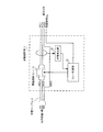
- FIG. 1 is a system configuration diagram for realizing an in-vehicle charging apparatus according to an embodiment of the present invention.
- an in-house facility 1 of a house 10 and an in-vehicle charging device 21 of a vehicle 2 are connected by a charging cable (power line) 4 via an earth leakage circuit breaker (EVSE) 3.
- EVSE earth leakage circuit breaker
- one end of the charging cable 4 is connected to the in-house facility 1 by a three-pole plug / outlet 5 made of, for example, a single-phase AC of 100 V AC and a ground wire.
- the other end of the charging cable 4 is connected to the in-vehicle charging device 21 of the vehicle 2 through a four-pole connection terminal including a CPLT line terminal in the three-pole vehicle side connection terminal, although not particularly illustrated. Yes.
- the earth leakage breaker 3 may be directly connected to the charging cable 4, but may be attached to a charging pole installed in advance. In any case, the plug / outlet 5 side of the charging cable 4 including the earth leakage breaker 3 is included in the infrastructure equipment.
- the home equipment 1 includes a distribution board 11, a house-side PLC terminal 12, an Internet modem 13, a television 14, and a personal computer 15.
- the distribution board 11 performs drawing of the power line from the outdoor utility pole and branching of the power line in the house 10.
- the house side PLC terminal 12 is connected to a power line branched from the distribution board 11 and controls the supply of charging power to the vehicle 2 side or establishes a PLC with the vehicle 2 side.
- the Internet modem 13 is connected to the house side PLC terminal 12 and transmits / receives an information signal (vehicle information) by the PLC.
- the television 14 and the personal computer 15 are connected to the Internet modem 13.
- the vehicle 2 is configured by an in-vehicle charging device 21 that receives charging power sent from the house-side PLC terminal 12 via the charging cable 4 and controls charging of the vehicle 2, a camera 22, an air conditioner 23, and the like. Yes.
- the vehicle-mounted charging device 21 is comprised by the storage battery 24, the charger 25, the vehicle side PLC communication control part 26, the memory
- illustration is abbreviate
- the above-described four-pole vehicle-side connection terminal for connecting the charging cable 4 to the in-vehicle charging device 21 is provided at a predetermined position of the body in the vehicle 2.
- This vehicle-side connection terminal is also illustrated. Is omitted.
- FIG. 2 is a detailed circuit configuration diagram of the leakage breaker 3 shown in FIG.
- the earth leakage circuit breaker 3 inputs two single-phase AC lines (AC1, AC2) and one ground line (GND) in the charging cable 4 on the in-home facility 1 side.
- Two single-phase alternating current lines (AC1, AC2) and one ground line (GND) are connected to the vehicle 2 via each contact point of the leakage breaker relay 31 of the leakage breaker 3 interposed between the wires (AC1, AC2).
- AC1, AC2 ground line
- the leakage breaker 3 further includes a leakage detection unit 32 that detects a change in the magnetic field when a leakage occurs on the power lines AC1 and AC2, and detects the leakage.
- a relay control unit 33 is provided that inputs the leakage detection signal detected by the unit 32 and the control signal Sg transmitted from the vehicle 2 and controls ON / OFF of the contact point of the leakage breaker relay 31.
- the relay control unit 33 turns off the contact point of the leakage breaker relay 31 when the leakage detection unit 32 detects leakage, regardless of the presence or absence of the control signal Sg from the vehicle 2 side. Further, when the leakage detection unit 32 detects leakage, when the control signal Sg transmitted from the vehicle 2 is an instruction to turn on the contact of the leakage breaker relay 31, the relay control unit 33 Control is performed to immediately turn off the contact of the earth leakage interrupting relay 31 after turning it on for a moment.
- the leakage detection unit 32 detects a leakage current, necessary vehicle information on the vehicle 2 side is transmitted to the in-home equipment 1 side in the momentary ON period of the leakage breaker relay 31, and after the vehicle information is transmitted By immediately turning off the earth leakage cutoff relay 31, the no-voltage state of the vehicle-side connection terminal of the charging cable 4 is maintained as long as possible to ensure electrical safety.
- FIG. 3 is a block diagram showing a detailed configuration of the in-vehicle charging device 21 shown in FIG.
- the in-vehicle charging device 21 includes a storage battery 24, a charger 25, a vehicle side PLC communication control unit 26, a storage unit 27, and a storage battery relay 28.
- the storage battery 24 supplies electric power for driving the electric motor (not shown) of the vehicle 2 shown in FIG.
- the charger 25 receives AC charging power sent from the home facility 1 shown in FIG. 1 through the charging cable 4 and converts it into DC to charge the storage battery 24.
- the vehicle-side PLC communication control unit 26 establishes a PLC when an information signal (vehicle information) on the vehicle 2 side is transmitted to the in-home facility 1 via the charging cable 4.
- the storage unit 27 stores various vehicle information on the vehicle 2 side.
- the storage battery relay 28 opens and closes the main circuit of the storage battery 24.
- the charger 25 receives a single-phase alternating current (AC1, AC2) power from the leakage circuit breaker 3 side shown in FIG. 2 and converts it into direct current power to charge the storage battery 24.
- the charging control unit 25b detects that the storage battery 24 and the charger power supply circuit 25a have completed preparation for charging and transmits a control signal Sg to the relay control unit 33 of the leakage breaker 3.
- the in-vehicle charging device 21 receives the single-phase AC lines (AC1, AC2) and the ground line (GND) of the charging cable 4.
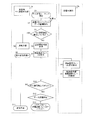
- FIG. 4 is a flowchart illustrating a flow in which the vehicle-side PLC communication control unit 26 of the in-vehicle charging device 21 performs the PLC processing in the first embodiment of the present invention. That is, in this flowchart, it is a process performed between the vehicle side PLC communication control unit 26 and the charge control unit 25b of the charger 25 in the in-vehicle charging device 21 shown in FIG. The flow of the process which transmits the vehicle information (data) of the vehicle 2 to the in-home equipment 1 by determining the initiative is shown.
- step S1 when a PLC transmission sequence for transmitting vehicle information of the vehicle 2 to the in-home facility 1 side using the charging cable 4 is started (step S1), the vehicle-side PLC communication control unit 26 stores the information. The transmission memory buffer capacity of the vehicle information stored in the unit 27 is detected (step S2). And the vehicle side PLC communication control part 26 determines whether the PLC communication connection (communication line) by the charging cable 4 is established between the vehicle 2 and the premises equipment 1 (house side PLC terminal 12). (Step S3).
- the vehicle-side PLC communication control unit 26 exchanges a regular PLC packet between the vehicle 2 and the in-home equipment 1 or detects the voltage of the AC line of the charging cable 4.
- the vehicle-side PLC communication control unit 26 sends vehicle information (data) of the vehicle 2 to the in-home equipment 1 while constantly detecting whether or not the communication connection between the vehicle 2 and the in-home equipment 1 is normal. Starts normal transmission (step S4).
- the vehicle side PLC communication control part 26 performs the normal transmission process of the regular packet by PLC, continuing the charge to the storage battery 24 (step S5).
- the vehicle-side PLC communication control unit 26 performs a transmission start determination process (step S3).
- the transmission start determination process is any condition (form) of the vehicle information of the vehicle 2 in order to establish the PLC communication connection by turning on the leakage breaker relay 31 of the leakage breaker 3 only when the vehicle information is transmitted. Is a process for determining whether to start transmission to the in-home facility 1.
- the vehicle information transmission start determination process is a process of determining the transmission start time point according to the condition (form) of the vehicle information.
- step S6 when the transmission start determination process is performed in step S6, the vehicle-side PLC communication control unit 26 turns on the leakage breaker relay 31 of the leakage breaker 3 shown in FIG.
- the charging control unit 25b is requested (step S7).
- the charging control unit 25b receives a request to turn on the leakage breaker relay 31 (step S8), and transmits the ON information on the leakage breaker relay 31 to the leakage breaker 3 as a control signal Sg via the control signal line.
- An ON request is made for the ground fault interrupt relay 31 (step S9).
- the vehicle-side PLC communication control unit 26 determines whether or not the PLC communication connection has been established (step S10). If the PLC communication connection cannot be established (NO in step S10), the charging cable is determined. It is determined that an error has occurred somewhere in 4 and transmission is impossible (step S11). On the other hand, if a PLC communication connection can be established in step S10 (YES in step S10), a process of transmitting vehicle information (data) of the vehicle 2 to the in-home equipment 1 is started (step S12), and predetermined vehicle information (data When the transmission of) is completed, the process proceeds to an OFF sequence (step B) of the leakage breaker relay 31 described later (step S13).
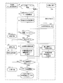
- FIG. 5 is a flowchart showing a flow in which the charge control unit 25b of the charger 25 performs the PLC processing in the second embodiment of the present invention. That is, in this flowchart, the process is performed between the vehicle-side PLC communication control unit 26 and the charging control unit 25b of the charger 25 in the in-vehicle charging device 21 shown in FIG. Shows the flow of processing for determining the initiative and transmitting the vehicle information (data) of the vehicle 2 to the in-house facility 1.
- step S1 when a PLC transmission sequence for transmitting the vehicle information of the vehicle 2 to the in-home facility 1 side using the charging cable 4 is started (step S1), the vehicle-side PLC communication control unit 26 Then, the transmission memory buffer capacity of the vehicle information stored in the storage unit 27 is detected (step S2).
- the vehicle-side PLC communication control unit 26 requests the charging control unit 25b to check whether or not the charger 25 of the vehicle charging device 21 is being charged (step S21). Then, the charging control unit 25b of the charger 25 makes a response of the charging execution status to the vehicle-side PLC communication control unit 26 (step S22).
- the vehicle-side PLC communication control unit 26 determines whether or not a leakage has occurred during the charging based on the detection information of the leakage detection unit 32 in the leakage breaker 3 (step S23). If leakage has occurred in charging cable 4 (YES in step S23), it is determined that vehicle information (data) cannot be transmitted (step S24), and the transmission process ends. In other words, when leakage occurs in the charging cable 4, the vehicle information (data) transmission process is immediately terminated without turning on the leakage interrupt relay 31.
- Step S25 the vehicle-side PLC communication control unit 26 determines whether charging is being performed using the charging cable 4.
- the vehicle-side PLC communication control unit 26 Normal transmission for sending vehicle information (data) to the in-house facility 1 is started (step S4), and normal transmission processing by PLC is executed (step S5).
- step S6 the vehicle information (data) of the vehicle 2 is set in any condition (data) in order to establish the PLC communication connection by turning on the leakage breaker relay 31 of the leakage breaker 3 only when the vehicle information is transmitted.
- This is a process for determining whether to start transmission to the in-house facility 1 in the form).
- the transmission start determination process is a process of determining the transmission start time point based on the condition (form) of the vehicle information (data).
- step S6 when vehicle information transmission start determination processing is performed in step S6, the vehicle-side PLC communication control unit 26 turns on the leakage breaker relay 31 of the leakage breaker 3 shown in FIG.
- the charge control unit 25b of the charger 25 is requested to perform PLC communication control by 25 (step S7).
- the charging control unit 25b receives a request to turn on the leakage breaker relay 31 (step S8), and transmits the ON information on the leakage breaker relay 31 to the leakage breaker 3 as a control signal Sg via the control signal line.
- An ON request is made for the ground fault interrupt relay 31 (step S9).
- the vehicle-side PLC communication control unit 26 determines whether or not the PLC communication connection has been established (step S10). If the PLC communication connection cannot be established (NO in step S10), the charging cable is determined. It is determined that an error has occurred somewhere in 4 and transmission is impossible (step S11). On the other hand, if the PLC communication connection can be established in step S10 (YES in step S10), the vehicle information (data) of the vehicle 2 starts to be transmitted to the in-house facility 1 (step S12), and the transmission of the vehicle information (data) is completed. If it does, it will transfer to the OFF sequence (B step) of the earth-leakage interruption
- the determination criteria for starting transmission of vehicle information include the following three determination criterion patterns (1) to (3).
- the vehicle information stored in the storage unit 27 of the in-vehicle charging device 21 is transmitted when the transmission memory buffer capacity is full.
- (2) Transmit when vehicle information with high priority is detected.
- (3) When the evaluation value determined by priority ⁇ data size (vehicle information size) exceeds a certain value, vehicle information is transmitted.
- the vehicle information stored in the storage unit 27 is transmitted in a batch based on any one of these three criterion patterns.
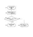
- FIG. 6 is a flowchart showing a flow of pattern 1 of the transmission start determination process in step S6 shown in FIG. 4 or 5 in the third embodiment of the present invention.
- the transmission start determination process of pattern 1 is a determination process for starting transmission by PLC when the transmission memory buffer capacity of the vehicle information accumulated in the storage unit 27 becomes full.
- step S ⁇ b> 31 when vehicle information transmission determination processing is started (step S ⁇ b> 31), the vehicle-side PLC communication control unit 26 of the in-vehicle charging device 21 transmits a vehicle information transmission memory buffer capacity already stored in the storage unit 27. Is calculated (step S32). Then, the vehicle-side PLC communication control unit 26 determines whether or not the data size of the transmission memory buffer capacity of the accumulated vehicle information is greater than or equal to a certain value (step S33).
- step S33 If the data size of the transmission memory buffer capacity is equal to or greater than a certain value (YES in step S33), the vehicle information transmission determination process is terminated (step S34), and the data size of the vehicle information transmission memory buffer capacity is When a certain value is reached, the PLC is established and data transmission is performed collectively.
- step S33 If the data size of the vehicle information transmission memory buffer stored in the storage unit 27 is not greater than or equal to a certain value in step S33 (NO in step S33), the process returns to step S2 in FIGS. 4 and 5 (step S35). ), The detection of the transmission memory buffer capacity of the vehicle information stored in the storage unit 27 is continued.
- the flow of the vehicle information transmission determination process shown in steps S31 to S34 described above means the following.
- charging is not performed, that is, when the leakage breaker relay 31 of the leakage breaker 3 is cut off and the PLC is not established, the leakage of the leakage breaker 3 when the vehicle information exceeds a certain amount
- the cut-off relay 31 is turned on, a communication connection by the PLC is temporarily established, and data is transmitted to the home-side PLC terminal 12 of the home equipment 1 in a lump.
- the vehicle side connection terminal of the charging cable 4 is brought into a non-voltage state to improve electrical safety. Secure.
- the vehicle information transmitted from the vehicle-mounted charging device 21 at this time can be monitored on the screen of the television 14 or the personal computer 15 of the in-home equipment 1.
- FIG. 7 is a flowchart showing a flow of pattern 2 of the transmission start determination process in step S6 shown in FIG. 4 or 5 in the third embodiment of the present invention.
- the transmission start determination process of pattern 2 is a determination process for determining the priority of the vehicle information in advance and transmitting the vehicle information having a high priority by the PLC.
- step S ⁇ b> 41 when vehicle information transmission determination processing is started (step S ⁇ b> 41), the vehicle-side PLC communication control unit 26 of the in-vehicle charging device 21 transmits a vehicle information transmission memory buffer capacity already stored in the storage unit 27. Is calculated (step S42). And the vehicle side PLC communication control part 26 determines whether the data size of the transmission memory buffer capacity
- step S44 based on the table A in which the priority for the category of the vehicle information, the priority coefficient, the data size example, and the evaluation value are compared, the new accumulation data of the vehicle information is stored.
- Check the priority For example, “failure detection information” in vehicle information has the highest priority at priority 5, and “travel history”, which is vehicle information that is periodically transmitted to the server, has the lowest priority at priority 1. Yes.
- correspond one by one is shown.
- step S44 the priority of the newly accumulated data of the vehicle information is confirmed based on the table A shown in FIG. 9, and there is vehicle information whose priority is not less than a specified value (for example, priority 4 or more). Whether or not (step S45).
- step S45 if it is detected that there is vehicle information with a priority equal to or higher than a specified value (for example, priority 4 or higher) (YES in step S45), the transmission determination process is terminated (step S46), and the PLC is established.
- the vehicle information stored in the transmission memory buffer is transmitted in a batch.
- the PLC is established and the vehicle information whose priority is a specified value or higher (for example, priority 4 or higher).
- vehicle information having a priority of 4 or more failure detection information, battery leakage detection information, user-driven communication request information, sensor camera screen (emergency), vehicle interior temperature abnormality information It is determined that there is charging rate decrease information, and only vehicle information with priority 4 or higher is immediately transmitted.
- step S45 If there is no vehicle information whose priority is a specified value or higher (eg, priority 4 or higher) in step S45 (NO in step S45), the process returns to step S2 in FIGS. 4 and 5 (step S47), and the storage unit 27 continues to detect the transmission memory buffer capacity of the vehicle information stored in the vehicle information.
- a specified value or higher eg, priority 4 or higher
- the flow of the vehicle information transmission determination process shown in steps S41 to S46 described above means the following.
- charging is not performed, that is, when the leakage breaker relay 31 of the leakage breaker 3 is cut off and the PLC is not established, the leakage breaker only when vehicle information having a priority level higher than a specified value exists. 3 is set to ON, communication connection by PLC is temporarily established, and only vehicle information data with a priority level equal to or higher than a specified value is transmitted to the home-side PLC terminal 12 of the in-house facility 1 in a lump. .
- the earth leakage breaker relay 31 of the earth leakage breaker 3 is turned off, the vehicle side connection terminal of the charging cable 4 is brought into a non-voltage state, and the electric Secure safety. Moreover, the vehicle information with high priority transmitted at this time can be monitored on the screen of the television 14 or the personal computer 15 of the in-home equipment 1.
- FIG. 8 is a flowchart showing a flow of pattern 3 of the transmission start determination process in step S6 shown in FIG. 4 or 5 in the third embodiment of the present invention.
- a priority coefficient is determined in advance for vehicle information, and determination for transmitting vehicle information whose evaluation value determined by priority coefficient ⁇ data size is equal to or greater than a specified value by the PLC is performed. It is processing.
- step S ⁇ b> 51 when vehicle information transmission determination processing is started (step S ⁇ b> 51), the vehicle-side PLC communication control unit 26 of the in-vehicle charging device 21 transmits a vehicle information transmission memory buffer capacity already stored in the storage unit 27. Is calculated (step S52). Then, the vehicle-side PLC communication control unit 26 determines whether or not the data size of the transmission memory buffer capacity of the vehicle information that has been accumulated in the storage unit 27 is greater than or equal to a certain value (step S53). If the data size of the transmission memory buffer capacity is greater than or equal to a certain value (YES in step S53), the transmission determination process is terminated (step S56).
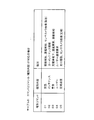
- FIG. 9 is a diagram showing a table A in which priorities, priority coefficients, data size examples, and evaluation values for vehicle information are compared. That is, in the above-described step S54, as shown in the table A of FIG. 9, the priority coefficient predetermined for each vehicle information type (category) is multiplied by the data size to obtain the vehicle information type ( An evaluation value is calculated for each category. For example, as shown in Table A, when the vehicle information is sensor camera information (emergency), since the priority coefficient is 100 and the data size is 40000 bytes, the evaluation value is calculated as 4,000,000.
- step S55 it is determined whether or not the evaluation value of the vehicle information calculated in step S54 is not less than a specified value. If the evaluation value of the vehicle information is not less than the specified value. (YES in step S55), the transmission determination process is terminated (step S56), the PLC is established, and only vehicle information whose evaluation value is equal to or greater than a specified value is transmitted.
- a specified value For example, according to Table A shown in FIG. 9, it is determined that there is a sensor camera image (emergency) having an evaluation value of vehicle information equal to or greater than a specified value of 4,000,000, the transmission determination process is terminated, and the storage unit The vehicle information stored in 27 is transmitted collectively by PLC. Alternatively, only vehicle information whose vehicle information evaluation value is equal to or greater than a specified value may be transmitted.
- step S55 If there is no vehicle information whose evaluation value is greater than or equal to the prescribed value in step S55 (NO in step S55), the process returns to step S2 in FIGS. 4 and 5 (step S57), and the vehicle information accumulated in the storage unit 27. Continue to detect the send memory buffer capacity.
- the flow of the vehicle information transmission determination process shown in steps S51 to S56 described above means the following.
- the leakage breaker only when vehicle information having an evaluation value equal to or greater than a specified value exists. 3 is set to ON, communication connection by PLC is temporarily established, and only vehicle information data whose evaluation value is equal to or greater than a specified value is transmitted to the home-side PLC terminal 12 of the home equipment 1 at a time. .
- the leakage breaker relay 31 of the leakage breaker 3 is immediately turned off, and the vehicle-side connection terminal of the charging cable 4 is brought into a non-voltage state to electrically Secure safety.
- the vehicle information with a high evaluation value transmitted at this time can be monitored on the screen of the television 14 or the personal computer 15 of the in-house facility 1. For example, when a suspicious person approaches a vehicle parked in a garage at night, the sensor camera image (emergency) is immediately displayed on the screen of the TV 14 or the personal computer 15 and is used for preventing theft of the vehicle. Can do.
- the effect by using the evaluation value of vehicle information as a transmission judgment standard is as follows.
- the “sensor vibration detection information” of the vehicle information shown in the table A of FIG. 9 has a priority of 3 and a data size of 16 bytes. Therefore, when the priority 5 or the memory buffer capacity is 256 Kbytes as the condition for the transmission determination criterion, the data (16 bytes) of “sensor vibration detection information” is not satisfied unless it is detected 16,000 times or more. Therefore, the vehicle information transmission standard is not reached unless a considerable number of vibrations are detected. Therefore, for example, even if the vehicle is parked for charging on an unpaved rough road and a vibration is detected due to a large vehicle passing on the side, there is no possibility that “sensor vibration detection information” is frequently transmitted.
- the threshold value of the vehicle information evaluation value is set to 1,500.
- the evaluation value of “sensor vibration detection information” in the vehicle information is 1,600, and therefore, the first “sensor vibration detection information” satisfies the condition of the transmission determination criterion. Therefore, since the evaluation value of the vehicle information becomes a certain value or more, the PLC can be immediately established and the vehicle information of “sensor vibration detection information” can be transmitted.
- the “room temperature abnormality information” of the vehicle information shown in Table A of FIG. 9 is a phenomenon that can occur on a daily basis, so the priority coefficient is set low (priority coefficient 10 And the vehicle information evaluation value is kept as low as 160. Thereby, the effect of suppressing the transmission frequency of the vehicle information of “indoor temperature abnormality” can be expected.
- FIG. 10 is a diagram showing a table B in which the type command is compared with the type content of the vehicle information.
- Types of vehicle information include emergency information, maintenance information, warning information, user information, and periodic transmission information.
- emergency information includes vehicle vibration detection information, leakage detection information, sensor camera image (emergency) information. And related information.
- the vehicle information transmission judgment criteria pattern 4 is transmitted based on the grouped vehicle information type contents as shown in Table B of FIG. Judgment can also be made.
- the criteria for judging transmission are as follows. That is, (1) the superiority or inferiority of transmission is determined by a type command. For example, if the type command is “01” in Table B, the corresponding vehicle information is immediately transmitted. (2) If the type command is “02” or “03”, for example, vehicle information is transmitted after 10 minutes, if “04”, the vehicle information is transmitted immediately, and if “05”, the vehicle is transmitted one hour later. As in the case of transmitting information, the transmission timing is determined according to the situation at that time.
- FIG. 11 is a flowchart showing a flow of processing in which the vehicle-side PLC communication control unit 26 shifts the leakage interrupt relay 31 to the OFF sequence and terminates the PLC in the fourth embodiment of the present invention.
- Step S61 first, following the step S13 of FIGS. 4 and 5, when the OFF sequence of the leakage breaker relay 31 is started (step S61), a packet is transmitted from the memory buffer already stored in the storage unit 27 ( Step S62), it is determined whether or not the transmission of the packet is successful (Step S63). If the transmission of the packet is successful (YES in step S63), the transmitted data is deleted from the accumulated memory buffer to increase the free space in the storage unit 27 (step S64).
- the vehicle-side PLC communication control unit 26 determines whether or not the accumulated memory buffer in the storage unit 27 is empty (step S65). If the accumulated memory buffer in the storage unit 27 is empty (YES in step S65), the vehicle-side PLC communication control unit 26 determines whether data is currently being received (step). S66). If the vehicle-side PLC communication control unit 26 is currently receiving data (YES in step S66), the process for determining whether or not the accumulated memory buffer in step S65 is empty and the data in step S66 are used. The process of determining whether or not data is being received is repeated, and the process waits for completion of data reception (step S67).
- step S68 the data transmission process is terminated (step S68), and the leakage control relay 31 is sent to the charge control unit 25b. Is requested to transmit a control signal Sg for turning off (step S69).
- the charging control unit 25b receives the OFF request signal of the leakage breaker relay 31 (step S70), and requests the relay control unit 33 of the leakage breaker 3 to turn off the leakage breaker relay 31 (step S71).
- the leakage interrupt relay 31 is turned off and the PLC communication connection is disconnected (step S72), and the OFF sequence of the leakage interrupt relay 31 ends (step S73).
- step S74 it is determined whether or not the PLC communication connection is established (step S74), and if the PLC communication connection is established (step S74). YES in step S74), a packet retransmission process is performed (step S75), and the process of determining whether or not the packet transmission in step S63 described above has been successful is repeated. If the PLC communication connection is not established in step S74 (NO in step S74), all data in the memory buffer in the storage unit 27 is deleted (step S76), and the memory buffer is emptied and new update information is created. Can be stored, and the process proceeds to the transmission end step in step S68.
- FIG. 12 is a flowchart showing a flow of PLC connection at the start of charging that is generally performed.
- the charging start sequence is started (step S81)
- the charging cable 4 is connected to the in-home device 1 on the input side of the leakage breaker 3 (step S82).
- the relay control part 33 of the earth leakage breaker 3 confirms whether the constant voltage is supplied to the earth leakage breaker 3 from the household device 1 and whether the control signal line is in an energized state (step S83). .
- the charging control unit 25b of the in-vehicle charging device 21 detects that the charging cable 4 is connected to the in-vehicle charging device 21 side (step S84), and determines whether the preparation for charging is completed (step S85). ). Here, if the preparation for charging is not completed (NO in step S85), the process waits until the preparation for charging is completed. If the preparation for charging is completed (YES in step S85), the charging control unit 25b of the in-vehicle charging device 21 detects the electric leakage. A control signal Sg is transmitted to the relay control unit 33 of the circuit breaker 3 through the control signal line (step S86).
- the relay control unit 33 of the leakage breaker 3 detects the control signal Sg and turns on the leakage breaker relay 31 (step S87). Then, the charging power (AC power) from the in-home equipment 1 is supplied to the in-vehicle charging device 21 and the storage battery relay 28 is turned on by the charging control unit 25b, so that charging of the storage battery 24 is started (step S88). ). And the vehicle side PLC communication control part 26 establishes the communication connection by PLC between the vehicle-mounted charging device 21 and the house side PLC terminal 12 (step S89), and complete
- the in-vehicle charging device 21 when the earth leakage breaker 3 is opened and charging by the charging cable 4 is not performed, the following three patterns are used.
- the communication connection by PLC is established only for the necessary minimum time by any one of the above, and only necessary vehicle information is transmitted to the in-house facility 1, and immediately after the vehicle information transmission is completed, the PLC communication connection is interrupted, The electrical safety of the vehicle side connection terminals is ensured.
- vehicle information to be communicated by PLC is stored (buffered) in the storage unit 27, and when the stored data exceeds a certain value, it is transmitted collectively by PLC.
- Priorities are set for each type of vehicle information data, and if there is vehicle information that is higher than a predetermined priority level, the stored data is transmitted in a batch by PLC.
- the leakage interrupt relay 31 of the leakage breaker 3 is turned off to disconnect the PLC communication connection (communication line).
- the leakage cutoff relay 31 of the leakage breaker 3 is turned on for the minimum necessary time to establish a PLC communication line, and the stored data can be transmitted in a batch. it can.
- the no-voltage state of the vehicle-side connection terminal of the charging cable 4 can be lengthened as much as possible, the electrical safety can be maintained at a relatively high level.
- the vehicle-side PLC communication control unit 26 always inquires of the charging control unit 25b whether or not charging is in progress, and if charging is in progress, starts communication by normal PLC and transmits vehicle information. In addition, when charging is not in progress, either when the vehicle information exceeds a predetermined data size, when there is vehicle information with a high priority, or when there is vehicle information with a high evaluation value Perform batch transmission. Note that if the vehicle-side PLC communication control unit 26 detects whether or not charging is currently being performed, it is not necessary to determine again whether or not a PLC communication line has been established.
- the capacity of the storage unit 27 can be effectively used to the maximum extent by deleting the vehicle information that has been transmitted from the storage unit 27. Further, when the transmission of the vehicle information cannot be completed and the communication line by the PLC is not established, the vehicle information lower than the predetermined priority is deleted. Thereby, even if transmission of vehicle information is not completed, when a communication line by PLC cannot be established, vehicle information with low priority can be deleted, and a free area in the storage unit 27 can be effectively secured.
- the vehicle-side PLC communication control unit 26 does not issue a command to turn on the leakage interrupt relay 31 to the charging control unit 25b when receiving information on leakage from the leakage breaker 3. That is, when a leakage occurs in the charging cable (power line) 4 and the leakage breaker relay 31 is turned off, a control signal Sg for turning on the leakage breaker relay 31 is transmitted to cause the leakage breaker relay 31 to instantaneously However, it is possible to prevent a problem that turns ON.
- the present invention has been specifically described based on several embodiments, the present invention is not limited to the above-described embodiments, and various modifications can be made without departing from the scope of the present invention. It is.
- the communication line establishment condition by the PLC while charging is stopped is not limited to the above three pattern conditions, but may be changed to a desired condition according to the user's desire.
- the description has been made on the assumption that an in-vehicle charging device mounted on an EV or HEV that can be charged from the outside, but the present invention is not limited to this, and a storage battery mounted on a normal gasoline vehicle. Needless to say, the present invention can also be applied to an in-vehicle charging apparatus for charging a battery.
- the present invention can be used as an in-vehicle charging device for HEVs and EVs, but can also be effectively used as an in-vehicle charging device for general vehicles such as gasoline vehicles.
Landscapes
- Engineering & Computer Science (AREA)
- Power Engineering (AREA)
- Transportation (AREA)
- Mechanical Engineering (AREA)
- Life Sciences & Earth Sciences (AREA)
- Sustainable Development (AREA)
- Sustainable Energy (AREA)
- Chemical & Material Sciences (AREA)
- Manufacturing & Machinery (AREA)
- Chemical Kinetics & Catalysis (AREA)
- Electrochemistry (AREA)
- General Chemical & Material Sciences (AREA)
- Charge And Discharge Circuits For Batteries Or The Like (AREA)
- Remote Monitoring And Control Of Power-Distribution Networks (AREA)
- Secondary Cells (AREA)
- Electric Propulsion And Braking For Vehicles (AREA)
Priority Applications (2)
| Application Number | Priority Date | Filing Date | Title |
|---|---|---|---|
| US14/007,735 US9409488B2 (en) | 2011-03-29 | 2012-03-27 | In-vehicle charging apparatus that charges a storage battery installed in a vehicle from a power supply provided outside the vehicle |
| EP12762866.7A EP2692570B1 (en) | 2011-03-29 | 2012-03-27 | In-vehicle charging device |
Applications Claiming Priority (2)
| Application Number | Priority Date | Filing Date | Title |
|---|---|---|---|
| JP2011-072050 | 2011-03-29 | ||
| JP2011072050A JP5849208B2 (ja) | 2011-03-29 | 2011-03-29 | 車載充電装置 |
Publications (1)
| Publication Number | Publication Date |
|---|---|
| WO2012132405A1 true WO2012132405A1 (ja) | 2012-10-04 |
Family
ID=46930180
Family Applications (1)
| Application Number | Title | Priority Date | Filing Date |
|---|---|---|---|
| PCT/JP2012/002109 Ceased WO2012132405A1 (ja) | 2011-03-29 | 2012-03-27 | 車載充電装置 |
Country Status (4)
| Country | Link |
|---|---|
| US (1) | US9409488B2 (enExample) |
| EP (1) | EP2692570B1 (enExample) |
| JP (1) | JP5849208B2 (enExample) |
| WO (1) | WO2012132405A1 (enExample) |
Cited By (1)
| Publication number | Priority date | Publication date | Assignee | Title |
|---|---|---|---|---|
| WO2014169927A1 (en) * | 2013-04-15 | 2014-10-23 | Volvo Truck Corporation | Method and arrangement for error detection during charging of an energy storage system |
Families Citing this family (13)
| Publication number | Priority date | Publication date | Assignee | Title |
|---|---|---|---|---|
| CN103097174B (zh) * | 2011-08-25 | 2015-05-06 | 丰田自动车株式会社 | 车辆、充电系统以及车辆的控制方法 |
| JP6168447B2 (ja) * | 2013-03-28 | 2017-07-26 | パナソニックIpマネジメント株式会社 | 給電制御装置 |
| JP6111500B2 (ja) * | 2013-03-29 | 2017-04-12 | パナソニックIpマネジメント株式会社 | 電気接続用コネクタ |
| JP6247460B2 (ja) * | 2013-06-14 | 2017-12-13 | 日立オートモティブシステムズ株式会社 | 電池制御装置 |
| JP5761265B2 (ja) | 2013-07-30 | 2015-08-12 | 株式会社デンソー | 車両用充電制御装置 |
| JP2016018295A (ja) * | 2014-07-07 | 2016-02-01 | 日立オートモティブシステムズ株式会社 | 情報処理システム |
| JP2016139865A (ja) * | 2015-01-26 | 2016-08-04 | 株式会社デンソー | 車両の周辺画像送信装置及びセキュリティシステム |
| KR101838508B1 (ko) * | 2016-01-07 | 2018-03-14 | 현대자동차주식회사 | 전기차 충전 방법 및 장치 |
| KR101996603B1 (ko) * | 2018-12-19 | 2019-07-04 | 중앙제어 주식회사 | 전기차 충전 시 전기차 충전기의 온도를 센싱하는 장치 |
| KR102837600B1 (ko) * | 2020-01-07 | 2025-07-22 | 주식회사 엘지에너지솔루션 | 시뮬레이션 시스템 및 데이터 분산 방법 |
| JP7666256B2 (ja) * | 2021-03-08 | 2025-04-22 | 株式会社デンソー | 電池管理システム |
| JP6947322B1 (ja) * | 2021-03-08 | 2021-10-13 | 株式会社デンソー | 電池管理システム |
| CN113525149A (zh) * | 2021-08-12 | 2021-10-22 | 长春捷翼汽车零部件有限公司 | 一种电能供给控制方法、装置、电子设备及存储介质 |
Citations (10)
| Publication number | Priority date | Publication date | Assignee | Title |
|---|---|---|---|---|
| WO2008143311A1 (ja) * | 2007-05-18 | 2008-11-27 | Toyota Jidosha Kabushiki Kaisha | 車両および車両の故障診断方法 |
| WO2009090813A1 (ja) * | 2008-01-15 | 2009-07-23 | Toyota Jidosha Kabushiki Kaisha | 電動車両の充電システム |
| JP2009303456A (ja) * | 2008-06-17 | 2009-12-24 | Autonetworks Technologies Ltd | 車両用電源制御装置 |
| JP2010004674A (ja) | 2008-06-20 | 2010-01-07 | Fujitsu Ten Ltd | 電子制御装置 |
| JP2010142001A (ja) * | 2008-12-10 | 2010-06-24 | Yazaki Corp | 充電監視装置 |
| JP2010166768A (ja) * | 2009-01-19 | 2010-07-29 | Fujitsu Ten Ltd | 制御装置、制御システム、制御方法 |
| JP2011010399A (ja) | 2009-06-24 | 2011-01-13 | Toyota Industries Corp | 車両充電システム |
| JP2011015530A (ja) * | 2009-07-02 | 2011-01-20 | Panasonic Corp | 漏電検知給電制御装置 |
| JP2011151717A (ja) * | 2010-01-25 | 2011-08-04 | Toyota Motor Corp | 車両の情報伝達装置およびそれを備える電動車両 |
| JP2011172363A (ja) * | 2010-02-17 | 2011-09-01 | Toyota Industries Corp | 充電制御装置及び車両充電システム |
Family Cites Families (10)
| Publication number | Priority date | Publication date | Assignee | Title |
|---|---|---|---|---|
| US5272431A (en) * | 1991-11-27 | 1993-12-21 | Nee Patrick W | Automatic power connector for recharging electric vehicles |
| JP3179387B2 (ja) | 1997-09-30 | 2001-06-25 | 日本電気移動通信株式会社 | 車両管理用データ伝送システム |
| JP4962939B2 (ja) | 2006-03-03 | 2012-06-27 | トヨタ自動車株式会社 | 車両および車両の情報機器 |
| JP2009165301A (ja) * | 2008-01-09 | 2009-07-23 | Denso Corp | 車両への電力供給制御装置および電力供給制御装置用のプログラム |
| JP5267050B2 (ja) * | 2008-10-30 | 2013-08-21 | 株式会社豊田自動織機 | バッテリ残量モニタシステム |
| JP5420883B2 (ja) * | 2008-11-17 | 2014-02-19 | トヨタ自動車株式会社 | 充電コネクタおよび充電ケーブルユニット |
| JP2011035975A (ja) | 2009-07-30 | 2011-02-17 | Toyota Motor Corp | 車両および車両の制御方法 |
| JP5417280B2 (ja) * | 2010-08-04 | 2014-02-12 | 株式会社日立製作所 | 蓄電池制御装置,充電スタンド及び蓄電池制御方法 |
| CN103181055B (zh) * | 2011-01-19 | 2015-08-12 | 本田技研工业株式会社 | 车辆充电系统 |
| US9542821B2 (en) * | 2012-01-10 | 2017-01-10 | Mitsubishi Electric Corporation | Home security system and vehicle-mounted system used by same |
-
2011
- 2011-03-29 JP JP2011072050A patent/JP5849208B2/ja not_active Expired - Fee Related
-
2012
- 2012-03-27 EP EP12762866.7A patent/EP2692570B1/en active Active
- 2012-03-27 WO PCT/JP2012/002109 patent/WO2012132405A1/ja not_active Ceased
- 2012-03-27 US US14/007,735 patent/US9409488B2/en active Active
Patent Citations (10)
| Publication number | Priority date | Publication date | Assignee | Title |
|---|---|---|---|---|
| WO2008143311A1 (ja) * | 2007-05-18 | 2008-11-27 | Toyota Jidosha Kabushiki Kaisha | 車両および車両の故障診断方法 |
| WO2009090813A1 (ja) * | 2008-01-15 | 2009-07-23 | Toyota Jidosha Kabushiki Kaisha | 電動車両の充電システム |
| JP2009303456A (ja) * | 2008-06-17 | 2009-12-24 | Autonetworks Technologies Ltd | 車両用電源制御装置 |
| JP2010004674A (ja) | 2008-06-20 | 2010-01-07 | Fujitsu Ten Ltd | 電子制御装置 |
| JP2010142001A (ja) * | 2008-12-10 | 2010-06-24 | Yazaki Corp | 充電監視装置 |
| JP2010166768A (ja) * | 2009-01-19 | 2010-07-29 | Fujitsu Ten Ltd | 制御装置、制御システム、制御方法 |
| JP2011010399A (ja) | 2009-06-24 | 2011-01-13 | Toyota Industries Corp | 車両充電システム |
| JP2011015530A (ja) * | 2009-07-02 | 2011-01-20 | Panasonic Corp | 漏電検知給電制御装置 |
| JP2011151717A (ja) * | 2010-01-25 | 2011-08-04 | Toyota Motor Corp | 車両の情報伝達装置およびそれを備える電動車両 |
| JP2011172363A (ja) * | 2010-02-17 | 2011-09-01 | Toyota Industries Corp | 充電制御装置及び車両充電システム |
Non-Patent Citations (1)
| Title |
|---|
| See also references of EP2692570A4 |
Cited By (5)
| Publication number | Priority date | Publication date | Assignee | Title |
|---|---|---|---|---|
| WO2014169927A1 (en) * | 2013-04-15 | 2014-10-23 | Volvo Truck Corporation | Method and arrangement for error detection during charging of an energy storage system |
| CN105121216A (zh) * | 2013-04-15 | 2015-12-02 | 沃尔沃卡车集团 | 用于在能量存储系统的充电期间的错误检测的方法和布置 |
| JP2016518803A (ja) * | 2013-04-15 | 2016-06-23 | ボルボトラックコーポレーション | エネルギー貯蔵システムを充電する間の誤りを検出する方法及び構造 |
| US9656568B2 (en) | 2013-04-15 | 2017-05-23 | Volvo Truck Corporation | Method and arrangement for error detection during charging of an energy storage system |
| CN105121216B (zh) * | 2013-04-15 | 2017-11-10 | 沃尔沃卡车集团 | 用于在能量存储系统的充电期间的错误检测的方法和装置 |
Also Published As
| Publication number | Publication date |
|---|---|
| EP2692570B1 (en) | 2020-07-22 |
| JP2012210007A (ja) | 2012-10-25 |
| EP2692570A1 (en) | 2014-02-05 |
| JP5849208B2 (ja) | 2016-01-27 |
| EP2692570A4 (en) | 2015-11-18 |
| US20140015494A1 (en) | 2014-01-16 |
| US9409488B2 (en) | 2016-08-09 |
Similar Documents
| Publication | Publication Date | Title |
|---|---|---|
| JP5849208B2 (ja) | 車載充電装置 | |
| CN104283239B (zh) | 用于移动终端的车载无线充电系统 | |
| CN104283238B (zh) | 用于移动终端的车载无线充电系统 | |
| EP2783899B1 (en) | Charging system and charging reservation method | |
| JP5561441B2 (ja) | 車両、車両用制御方法および受電設備 | |
| US9895986B2 (en) | Electric vehicle externally chargeable by two different methods | |
| US9481324B2 (en) | Vehicle battery charger | |
| KR101821008B1 (ko) | 전기 자동차 충전 장치 | |
| CN204497817U (zh) | 电动汽车的无线充电系统 | |
| KR101821007B1 (ko) | 차량 충전 장치 및 충전 방법 | |
| JP6015038B2 (ja) | 車両および車両用制御方法 | |
| EP2996897A1 (en) | Method and arrangement for controlling charging of an energy storage system | |
| GB2506185A (en) | Fault detection system for electric vehicle charging | |
| CN103928954A (zh) | 车辆用充电装置 | |
| KR102320041B1 (ko) | 스마트그리드용 전기자동차의 양방향 충방전 방법 및 장치 | |
| JP5853209B2 (ja) | 電力線通信システム及び車両 | |
| JP2020127304A (ja) | 車両 | |
| JP5835180B2 (ja) | 車両 | |
| JP5353082B2 (ja) | 車両用電源制御装置 | |
| CN109193893A (zh) | 一种防止控制蓄电池亏电的方法及系统 | |
| JP2016005327A (ja) | 非接触受電装置 | |
| KR20160106311A (ko) | 전기 자동차 충전 시스템 | |
| CN117002259A (zh) | 一种对外放电控制系统、方法及车辆 | |
| CN112319300A (zh) | 一种智能充电器及其智能充电管理方法 | |
| CN119329343B (zh) | 一键开盖与可视化充电的家用充电桩及其电路控制方法 |
Legal Events
| Date | Code | Title | Description |
|---|---|---|---|
| 121 | Ep: the epo has been informed by wipo that ep was designated in this application |
Ref document number: 12762866 Country of ref document: EP Kind code of ref document: A1 |
|
| WWE | Wipo information: entry into national phase |
Ref document number: 2012762866 Country of ref document: EP |
|
| WWE | Wipo information: entry into national phase |
Ref document number: 14007735 Country of ref document: US |
|
| NENP | Non-entry into the national phase |
Ref country code: DE |