WO2012132134A1 - ラック型の電源装置及び脱着コネクタを備える電池パック - Google Patents
ラック型の電源装置及び脱着コネクタを備える電池パック Download PDFInfo
- Publication number
- WO2012132134A1 WO2012132134A1 PCT/JP2011/079133 JP2011079133W WO2012132134A1 WO 2012132134 A1 WO2012132134 A1 WO 2012132134A1 JP 2011079133 W JP2011079133 W JP 2011079133W WO 2012132134 A1 WO2012132134 A1 WO 2012132134A1
- Authority
- WO
- WIPO (PCT)
- Prior art keywords
- terminal
- battery pack
- main
- connector
- rack body
- Prior art date
- Legal status (The legal status is an assumption and is not a legal conclusion. Google has not performed a legal analysis and makes no representation as to the accuracy of the status listed.)
- Ceased
Links
Images






Classifications
-
- H—ELECTRICITY
- H01—ELECTRIC ELEMENTS
- H01M—PROCESSES OR MEANS, e.g. BATTERIES, FOR THE DIRECT CONVERSION OF CHEMICAL ENERGY INTO ELECTRICAL ENERGY
- H01M10/00—Secondary cells; Manufacture thereof
- H01M10/42—Methods or arrangements for servicing or maintenance of secondary cells or secondary half-cells
- H01M10/425—Structural combination with electronic components, e.g. electronic circuits integrated to the outside of the casing
-
- H—ELECTRICITY
- H01—ELECTRIC ELEMENTS
- H01M—PROCESSES OR MEANS, e.g. BATTERIES, FOR THE DIRECT CONVERSION OF CHEMICAL ENERGY INTO ELECTRICAL ENERGY
- H01M10/00—Secondary cells; Manufacture thereof
- H01M10/42—Methods or arrangements for servicing or maintenance of secondary cells or secondary half-cells
- H01M10/4207—Methods or arrangements for servicing or maintenance of secondary cells or secondary half-cells for several batteries or cells simultaneously or sequentially
-
- H—ELECTRICITY
- H01—ELECTRIC ELEMENTS
- H01M—PROCESSES OR MEANS, e.g. BATTERIES, FOR THE DIRECT CONVERSION OF CHEMICAL ENERGY INTO ELECTRICAL ENERGY
- H01M10/00—Secondary cells; Manufacture thereof
- H01M10/42—Methods or arrangements for servicing or maintenance of secondary cells or secondary half-cells
- H01M10/425—Structural combination with electronic components, e.g. electronic circuits integrated to the outside of the casing
- H01M10/4257—Smart batteries, e.g. electronic circuits inside the housing of the cells or batteries
-
- H—ELECTRICITY
- H01—ELECTRIC ELEMENTS
- H01M—PROCESSES OR MEANS, e.g. BATTERIES, FOR THE DIRECT CONVERSION OF CHEMICAL ENERGY INTO ELECTRICAL ENERGY
- H01M10/00—Secondary cells; Manufacture thereof
- H01M10/42—Methods or arrangements for servicing or maintenance of secondary cells or secondary half-cells
- H01M10/48—Accumulators combined with arrangements for measuring, testing or indicating the condition of cells, e.g. the level or density of the electrolyte
- H01M10/482—Accumulators combined with arrangements for measuring, testing or indicating the condition of cells, e.g. the level or density of the electrolyte for several batteries or cells simultaneously or sequentially
-
- H—ELECTRICITY
- H01—ELECTRIC ELEMENTS
- H01M—PROCESSES OR MEANS, e.g. BATTERIES, FOR THE DIRECT CONVERSION OF CHEMICAL ENERGY INTO ELECTRICAL ENERGY
- H01M50/00—Constructional details or processes of manufacture of the non-active parts of electrochemical cells other than fuel cells, e.g. hybrid cells
- H01M50/20—Mountings; Secondary casings or frames; Racks, modules or packs; Suspension devices; Shock absorbers; Transport or carrying devices; Holders
- H01M50/204—Racks, modules or packs for multiple batteries or multiple cells
-
- H—ELECTRICITY
- H01—ELECTRIC ELEMENTS
- H01M—PROCESSES OR MEANS, e.g. BATTERIES, FOR THE DIRECT CONVERSION OF CHEMICAL ENERGY INTO ELECTRICAL ENERGY
- H01M50/00—Constructional details or processes of manufacture of the non-active parts of electrochemical cells other than fuel cells, e.g. hybrid cells
- H01M50/20—Mountings; Secondary casings or frames; Racks, modules or packs; Suspension devices; Shock absorbers; Transport or carrying devices; Holders
- H01M50/296—Mountings; Secondary casings or frames; Racks, modules or packs; Suspension devices; Shock absorbers; Transport or carrying devices; Holders characterised by terminals of battery packs
-
- H—ELECTRICITY
- H01—ELECTRIC ELEMENTS
- H01M—PROCESSES OR MEANS, e.g. BATTERIES, FOR THE DIRECT CONVERSION OF CHEMICAL ENERGY INTO ELECTRICAL ENERGY
- H01M50/00—Constructional details or processes of manufacture of the non-active parts of electrochemical cells other than fuel cells, e.g. hybrid cells
- H01M50/50—Current conducting connections for cells or batteries
- H01M50/502—Interconnectors for connecting terminals of adjacent batteries; Interconnectors for connecting cells outside a battery casing
- H01M50/503—Interconnectors for connecting terminals of adjacent batteries; Interconnectors for connecting cells outside a battery casing characterised by the shape of the interconnectors
-
- Y—GENERAL TAGGING OF NEW TECHNOLOGICAL DEVELOPMENTS; GENERAL TAGGING OF CROSS-SECTIONAL TECHNOLOGIES SPANNING OVER SEVERAL SECTIONS OF THE IPC; TECHNICAL SUBJECTS COVERED BY FORMER USPC CROSS-REFERENCE ART COLLECTIONS [XRACs] AND DIGESTS
- Y02—TECHNOLOGIES OR APPLICATIONS FOR MITIGATION OR ADAPTATION AGAINST CLIMATE CHANGE
- Y02E—REDUCTION OF GREENHOUSE GAS [GHG] EMISSIONS, RELATED TO ENERGY GENERATION, TRANSMISSION OR DISTRIBUTION
- Y02E60/00—Enabling technologies; Technologies with a potential or indirect contribution to GHG emissions mitigation
- Y02E60/10—Energy storage using batteries
Definitions
- the present invention relates to a rack-type power supply device in which a plurality of battery packs including a plurality of rechargeable unit cells are housed in a rack, and a battery pack including a detachable connector that is detachably attached to the rack.
- a power supply device that charges a battery with commercial power at midnight power or solar power generation and uses this battery power as a power source can be used in homes and factories to reduce electricity charges, and back up various electrical equipment. It can be conveniently used as a power source.
- This type of power supply device includes a large number of rechargeable unit cells in order to increase the capacity. Many unit cells can be connected in series to increase the output voltage, or connected in parallel to increase the output current. Furthermore, in order to connect a large number of unit cells efficiently, in this type of power supply apparatus, a plurality of battery packs formed by connecting a predetermined number of unit cells in a predetermined array are connected in series or in parallel.
- Patent Document 1 As a power supply device including a plurality of battery packs, a structure in which box-shaped battery packs are arranged in a rack and stored has been developed. (See Patent Document 1)
- battery packs each including a plurality of unit cells are stored in a rack while being aligned, and the output terminals of the battery packs are connected in series on the side of the rack to take out a desired output.
- a power storage device in which a plurality of battery packs are housed in a rack, and output terminals are connected in series on the rear side of the rack to take out a desired output.
- These power supply devices can increase the output voltage by connecting a plurality of battery packs in series.
- the output voltage increases as the number of battery packs connected in series increases, there is a problem that these wirings become dangerous.
- the output voltage of the entire power supply device is as high as several hundred volts, so it is extremely dangerous if an operator gets an electric shock during work. is there.
- the work of connecting the output terminals of a plurality of battery packs on the back side of the rack requires wiring after the plurality of battery packs are stored in the rack at the site where the power supply is installed. In many cases, the work is performed in a dark and narrow place on the side, which not only lowers the efficiency of the work but also decreases the safety.
- a battery pack including a large number of unit cells has an electronic circuit that detects and processes various battery information such as battery voltage, remaining capacity, and battery temperature in order to manage the state of these batteries.
- a battery pack including these electronic circuits uses the power of a built-in unit cell to activate the electronic circuit. For this reason, in the battery pack, when these electronic circuits are always in an operating state, even when the battery pack is not connected to the main device, the electronic circuit consumes power wastefully and the remaining capacity of the battery is reduced. For this reason, when the battery pack is set in the main device and used, there is a drawback that the use time is shortened.
- power supply apparatus comprising a shutdown circuit for preventing wasteful power consumption by stopping power supply to the circuit in a state where the battery pack is not used has been developed.
- a shutdown circuit for preventing wasteful power consumption by stopping power supply to the circuit in a state where the battery pack is not used.
- this power supply device detects the voltage of the signal terminal connected to the main device to be attached and detects the attachment / detachment with the main device, it is necessary to connect the signal terminal of the battery pack to the signal terminal of the main device. is there. For this reason, in a power supply device that houses a plurality of battery packs in a rack, it is necessary to individually connect the signal terminals of each battery pack to a controller or the like on the rack side, which takes time and reduces work efficiency. There are drawbacks. If the working time is lengthened, the safety of the work is further reduced.
- An important object of the present invention is to connect a plurality of battery packs efficiently and safely while storing a plurality of battery packs each including a plurality of rechargeable cells arranged in a fixed position on the rack body.
- An object of the present invention is to provide a battery pack including a rack type power supply device and a detachable connector.
- another important object of the present invention includes with a very simple circuit structure, the desorption of the rack body to reliably detect the rack-type power supply and release connector capable of reducing wasteful consumption of the battery It is to provide a battery pack.
- the rack-type power supply device of the present invention includes a plurality of battery packs 1 and a rack body 2 on which these battery packs 1 are detachably mounted.
- the battery pack 1 includes a battery 10 composed of a plurality of unit cells 11 connected in series and / or in parallel to each other, an outer case 12 that houses the battery 10, and a back surface of the outer case 12. And a positive and negative output terminal 13 connected to the output side of the battery 10.
- the rack body 2 includes a plurality of storage spaces 20 for storing the respective battery packs 1 at fixed positions, and faces the positive and negative output terminals 13 provided on the battery pack 1 on the inner surface of each storage space 20.
- the output terminal 13 is provided with an input terminal 23 that is electrically connected to the facing surface 22 in a fitted state.
- the rack body 2 has these input terminals 23 wired in series and / or in parallel on the back surface side of the facing surface 22.
- the rack-type power supply device connects a plurality of battery packs 1 in series and / or in parallel with the battery pack 1 guided to the storage space 20 of the rack body 2 and the output terminal 13 connected to the input terminal 23. is doing.
- the rack-type power supply unit described above efficiently and safely connects multiple battery packs while storing a plurality of battery packs each containing a plurality of rechargeable cells aligned in a fixed position on the rack body. Can be done. That is, the power supply apparatus described above includes input terminals that are electrically connected in a state where the positive and negative output terminals of the battery pack are fitted to the opposing surfaces of the plurality of storage spaces provided in the rack body. This is because the terminals are wired in series and / or in parallel on the back side of the opposing surface. In this power supply apparatus, after the battery pack is stored in the rack body, wiring is not performed on the back side of the rack body, but the input terminals are previously wired in a predetermined connection state on the back side.
- the rack-type power supply device of the present invention can detachably connect the output terminal 13 of the battery pack 1 and the input terminal 23 of the rack body 2 via the detachable connector 3.
- the power supply apparatus described above can detach and attach the output terminal and the input terminal very easily by detaching the detachable connector at the time of detaching the battery pack. Also, there is a feature that the output terminal and the input terminal can be connected while being accurately positioned by detaching via the detachable connector.
- the rack-type power supply device of the present invention includes an electronic circuit 30 in which the battery pack 1 detects and monitors the state of the plurality of unit cells 11, a shutdown circuit 31 that controls the electronic circuit 30 on and off, and the battery pack 1. Is connected to the mounting detection terminal 14 in a state where the battery pack 1 is mounted at a fixed position. 24 can be provided.
- the shutdown circuit 31 turns on the electronic circuit 30 when the mounting detection terminal 14 and the connecting terminal 24 are connected, and turns off the electronic circuit 30 when the mounting detection terminal 14 and the connecting terminal 24 are not connected. It can be turned off.
- the power supply apparatus described above has a feature that can reliably detect the battery pack mounted on the rack body and effectively prevent useless consumption of the battery when the battery pack is not mounted on the rack body. This is because the power supply device detects the battery pack mounting state when the mounting detection terminal and the connecting terminal are connected, and turns off the built-in electronic circuit in the shutdown circuit when the battery pack is not mounted on the rack body. It is because it controls.
- a short circuit 25 attachment detection terminal 14 is provided with a pair of contact terminals 14A, connecting terminals 24, to short the pair of contact terminals 14A, the shutdown circuit 31, a pair of contact terminals
- the electronic circuit 30 can be controlled to be turned on by detecting a short circuit of 14A.
- the power supply apparatus described above can reliably detect the connection state between the mounting detection terminal and the connection terminal while having an extremely simple circuit configuration.
- the rack body 2 includes a power supply controller that controls charging / discharging of a plurality of battery packs 1 connected to each other, and the power supply controller receives power input from the battery pack 1.
- a main switch 51 that shuts off and a control circuit 50 that controls the main switch 51 to be turned on and off are provided.
- the control circuit 50 can determine the connection state of the battery pack 1 and control the main switch 51 to be turned on and off.
- the power supply controller that controls charging / discharging of the plurality of connected battery packs determines the connection state of the battery pack and controls the main switch to be turned on / off. The occurrence of arc can be reliably prevented.
- the rack body 2 includes a main attachment / detachment detection terminal 46 that detects the connection state of the battery pack 1, and the battery pack 1 is connected to the main attachment / detachment detection terminal 46.
- a terminal 16 may be provided.
- the main attachment / detachment detection terminal 46 and the main connection terminal 16 can be connected to each other after the output terminal 13 and the input terminal 23 are connected at the timing when the battery pack 1 is attached to the rack body 2.
- the control circuit 50 turns off the main switch 51 when any of the main attachment / detachment detection terminals 46 and the main connection terminal 16 are not connected, and all the main attachment / detachment detection terminals 46 and the main connection terminals 16 are turned off.
- the main switch 51 can be turned on.
- the above rack-type power supply device is connected to the battery pack via the main attachment / detachment detection terminal and the main connection terminal that are connected after the output terminal and the input terminal are connected at the timing when the battery pack is mounted on the rack body. Since the state is detected and the main switch is turned on, the battery pack can be attached and detached more safely while reliably preventing the occurrence of an arc when the battery pack is attached and detached.
- the rack body 2 includes a main detachment detection terminal 46 and a sub detachment detection terminal 47 for detecting the mounting state of the battery pack 1, and the battery pack 1 is connected to the main detachment detection terminal 46.
- the main connection terminal 16 to be connected and the sub connection terminal 17 connected to the sub attachment / detachment detection terminal 47 can be provided.
- the main attachment / detachment detection terminal 46 and the main connection terminal 16 are connected to each other after the output terminal 13 and the input terminal 23 are connected at the timing when the battery pack 1 is attached to the rack body 2.
- the detection terminal 47 and the sub connection terminal 17 can be connected to each other before the output terminal 13 and the input terminal 23 are connected at the timing when the battery pack 1 is mounted on the rack body 2.
- the power supply device includes the main switch 51 when the control circuit 50 is in a state where the sub-detachment detection terminal 47 and the sub-connection terminal 17 are connected and the main attachment / detachment detection terminal 46 and the main connection terminal 16 are not connected. In the off state, the main switch 51 can be turned on when the sub attachment / detachment detection terminal 47 and the sub connection terminal 17 are connected and the main attachment / detachment detection terminal 46 and the main connection terminal 16 are connected.
- the above rack-type power supply device has a main attachment / detachment detection terminal, a main connection terminal, an output terminal, and an input terminal that are connected after the output terminal and the input terminal are connected at the timing when the battery pack is attached to the rack body.
- the connection state of the battery pack is detected and the main switch is controlled to be turned on and off via the connected sub-detachment detection terminal and the sub connection terminal, so that the connection state of the battery pack can be detected more accurately. .
- desorption of a battery can be prevented more reliably, and high reliability can be implement
- this power supply device can reliably turn off the main switch before and after the output terminal and the input terminal are connected. Therefore, even in a power supply device that connects a plurality of battery packs in various connection states, It is possible to reliably prevent the occurrence of arcs during detachment.
- the battery pack having the detachable connector of the present invention includes an outer case 12 that is detachably set on the rack body 2 and a plurality of unit cells that are housed in the outer case 12 and connected in series and / or in parallel. 11 and a detachable connector 3 for connecting the output of the battery 10 to the rack body 2.
- the detachable connector 3 includes a first connector 3A that is fixed to the exterior case 12, and a second connector 3B that is fixed to the rack body 2 with the first connector 3A being detachably connected thereto.
- the first connector 3 ⁇ / b> A includes an output terminal 13 that is fixed to the back surface of the outer case 12 and connected to the battery 10.
- the second connector 3B includes an input terminal 23 to which the output terminal 13 is connected and which connects the batteries 10 in series or in parallel on the rack body 2 side.
- the first connector 3 ⁇ / b> A is coupled to the second connector 3 ⁇ / b> B in a state where the outer case 12 is set on the rack body 2, and the battery 10 is connected to the input terminal 23.
- Battery packs equipped with the above detachable connectors have the feature that they can be mounted efficiently and safely in place on the rack body. This is because the above battery pack is detachably set to the rack body via a detachable connector comprising a first connector fixed to the exterior case and a second connector fixed to the rack body. is there. Further, the detachable connector has a battery pack since the first connector has an output terminal and the second connector has an input terminal to which the output terminal is connected and the battery is connected in series or in parallel on the rack body side. When attaching and detaching, the output terminal and the input terminal can be connected while accurately positioning.
- the input terminal of the second connector has a structure in which the battery is connected in series or in parallel on the rack body side
- the battery pack is set in the rack body in which the input terminals are wired in advance, and the output terminal is connected to the input terminal. Can be connected safely.
- the battery pack including the detachable connector of the present invention includes an electronic circuit 30 that detects and monitors the state of the plurality of unit cells 11, and a shutdown circuit 31 that controls the electronic circuit 30 to be turned on and off, and further includes a first connector.
- 3A can include a mounting detection terminal 14 for detecting that the outer case 12 is mounted at a fixed position of the rack body 2
- the second connector 3B can include a connection terminal 24 connected to the mounting detection terminal 14.
- the shutdown circuit 31 turns on the electronic circuit 30 when the attachment detection terminal 14 and the connection terminal 24 are connected, and turns off the electronic circuit 30 when the attachment detection terminal 14 and the connection terminal 24 are not connected. State.
- the battery pack described above has a feature that can reliably detect the mounting of the battery on the rack body and effectively prevent the wasteful consumption of the battery when the battery pack is not mounted on the rack body. That is, when the battery pack is connected to the mounting detection terminal and the connecting terminal, the battery pack is detected and the electronic circuit incorporated in the shutdown circuit is turned off when the battery pack is not attached to the rack body. It is because it controls.
- a battery pack comprising a release connector of the present invention includes a mounting detection terminal 14 a pair of contact terminals 14A, a short circuit 25 connecting terminals 24 to short-circuit the pair of contact terminals 14A, the shutdown circuit 31, a pair of contact terminals
- the electronic circuit 30 can be controlled to be turned on by detecting a short circuit of 14A.
- the above battery pack can reliably detect the connection state between the attachment detection terminal and the connection terminal while having an extremely simple circuit configuration.
- the second connector 3B includes a main detachment detection terminal 46 for detecting the connection state of the first connector 3A, and the first connector 3A is connected to the main detachment detection terminal 46.
- the main connection terminal 16 can be provided.
- the main attachment / detachment detection terminal 46 and the main connection terminal 16 may be connected to each other after the output terminal 13 and the input terminal 23 are connected at the timing when the outer case 12 is attached to the rack body 2.
- This battery pack can detect the connection state of the main attachment / detachment detection terminal 46 and the main connection terminal 16 to detect the attachment state of the outer case 12 and the rack body 2.
- the above battery pack is provided with a main connector detection terminal and a main connection terminal to be connected after the output terminal and the input terminal are connected at the timing of mounting on the rack body. And the connection state of the main connection terminal can be detected, and the mounting state between the outer case and the rack body can be detected.
- the second connector 3B includes the main detachment detection terminal 46 and the sub detachment detection terminal 47 for detecting the connection state of the first connector 3A
- the first connector 3A includes the main detachment connector.
- the main connection terminal 16 connected to the detection terminal 46 and the sub connection terminal 17 connected to the sub attachment / detachment detection terminal 47 can be provided.
- This battery pack detects the connection state between the main attachment / detachment detection terminal 46 and the main connection terminal 16 and the connection state between the sub attachment / detachment detection terminal 47 and the sub connection terminal 17 to determine the attachment state between the outer case 12 and the rack body 2. Can be detected.
- the battery pack described above is connected to the main body of the rack after the output terminal and the input terminal are connected, and before the main connection / disconnection detection terminal, the main connection terminal, and the output terminal and the input terminal are connected. Since the connection / disconnection detection terminal and the sub connection terminal are provided in the connection / disconnection connector, in addition to the connection state of the main connection / disconnection detection terminal and the main connection terminal, the connection state of the sub connection / disconnection detection terminal and the sub connection terminal is detected Thus, it is possible to more accurately detect the mounting state of the outer case and the rack body, and to improve the safety at the time of attaching to and detaching from the rack body.
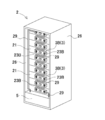
- FIG. 1 is a perspective view of a rack-type power supply device according to an embodiment of the present invention.
- FIG. 2 is a rear perspective view of the rack-type power supply device shown in FIG. 1.
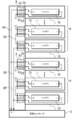
- FIG. 2 is a vertical sectional view of the rack-type power supply device shown in FIG. 1.
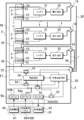
- FIG. 2 is a block circuit diagram of the rack-type power supply device shown in FIG. 1. It is a block circuit diagram of the battery pack concerning one Example of this invention.
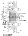
- It is a schematic exploded sectional view showing an example of a detachable connector.
- It is a schematic sectional drawing which shows the connection structure of the attachment / detachment connector shown in FIG.
- It is a block circuit diagram of the rack-type power supply device concerning the other Example of this invention.
- FIG. 10 is a schematic exploded sectional view showing a detachable connector of the rack type power supply device shown in FIG. 9. It is a general
- the rack-type power supply device of the present invention can be used as a storage power storage facility.
- a power supply system that is charged with sunlight or midnight power and discharged when necessary, or daytime It can also be used as a power source for street lamps that charge the sunlight and discharge at night, and as a backup power source for traffic lights and servers that are driven during a power failure.
- the plurality of battery packs 1 are stored in a storage space 20 provided in the rack body 2 at a predetermined interval, and are arranged in alignment with the fixed positions of the rack body 2.
- the battery pack 1 includes a battery 10 composed of a plurality of unit cells 11 connected in series and / or in parallel to each other, an outer case 12 that houses the battery 10, and a back surface of the outer case 12. And a positive and negative output terminal 13 connected to the output side of the battery 10.
- the battery 10 has a plurality of unit cells 11 connected in series and in parallel, and the output voltage is set to several tens of volts.
- This unit cell 11 is a lithium ion secondary battery.
- the battery 10 in which the unit cell 11 is a lithium ion secondary battery can increase the output with respect to volume and weight.
- lithium polymer batteries and nickel metal hydride batteries can be used instead of lithium ion batteries. Therefore, this invention does not specify a unit cell as a lithium ion battery, and can use all the batteries which can be charged as a unit cell.
- the battery 10 in the figure is provided with a temperature sensor 39 for temperature detection. The temperature sensor may be provided for each unit cell, or only the unit cell at a specific position may be monitored.
- the outer case 12 has a thick box shape as a whole, and houses a battery 10 composed of a plurality of unit cells 11.
- the outer case 12 is made of a material having excellent insulating properties, for example, resin.
- the exterior case 12 is formed in a shape and size that can be stored in the storage space 20 of the rack body 2.
- the battery pack 1 shown in the figure is provided with positioning collars 19 that protrude from both sides of the outer case 12 so that the battery pack 1 can be inserted into the storage space 20 of the rack body 2 to a predetermined depth.
- the battery pack 1 is placed in a fixed position with the positioning collar 19 in contact with the opening edge of the rack body 2 in a state of being stored in the storage space 20 of the rack body 2.
- the battery pack 1 can fix the positioning collar 19 to the opening edge of the rack body 2 via a connecting tool such as a set screw.
- the positive and negative output terminals 13 are exposed on the back surface of the outer case 12.
- the positive and negative output terminals 13 are connected to the positive and negative outputs of the battery 1 inside the outer case 12.
- the output terminal 13 is connected to an input terminal 23 provided at the back of the storage space 20 in a state where the battery pack 1 is inserted into the storage space 20 of the rack body 2.
- the output terminal 13 and the input terminal 23 are configured to be electrically connected to each other with a fitting structure.
- An example of the connection structure of the output terminal 13 and the input terminal 23 is shown in the schematic sectional views of FIGS.
- the output terminal 13 includes a columnar insertion portion 13A
- the input terminal 23 includes a cylindrical connection ring portion 23A into which the insertion portion 13A is inserted.
- the insertion portion 13A of the output terminal 13 is inserted into the connection ring portion 23A of the input terminal 23, and the outer peripheral surface of the insertion portion 13A contacts the inner peripheral surface of the connection ring portion 23A and is electrically connected to each other.
- the output terminal and the input terminal are not necessarily specified in the above shape, and may be other structures that are detachably connected to each other and connected in a low resistance state.
- the battery pack 1 includes an electronic circuit 30 including a microcomputer that detects and monitors the state of the plurality of unit cells 11.
- the electronic circuit 30 includes various circuits that detect battery information such as temperatures and voltages of a plurality of unit cells 11 and charging and discharging currents, circuits that detect and calculate the full charge and remaining capacity of the battery from these battery information, Alternatively, a protection circuit for monitoring whether or not the battery is normal is provided.
- the rack body 2 includes a plurality of storage spaces 20 for storing a plurality of battery packs 1.
- the rack main body 2 shown in the figure has storage spaces 20 provided in a plurality of stages in the vertical direction so that the battery pack 1 is stored in each stage.
- the rack main body 2 shown in FIGS. 1 to 3 is provided with ten storage spaces 20 extending vertically in the vertical direction so that the battery packs 1 can be aligned while being stored in a horizontal position in each storage space 20.
- the rack main body can be provided with storage spaces extended vertically in a plurality of rows in the left-right direction, and the battery packs can be stored side by side in a vertical posture in each storage space.
- the rack body can also be provided with storage spaces provided in a plurality of rows in the left-right direction in a plurality of stages in the vertical direction.
- the rack body 2 in FIG. 1 divides the inside of the rack body 2 into a plurality of storage spaces 20 by providing a plurality of rows of support plates 27 at predetermined intervals between side walls 26 provided on both sides.
- the rack body 2 is configured such that the inner shape of the storage space 20 is shaped and sized along the outer shape of the battery pack 1 so that each battery pack 1 can be accurately placed at a fixed position in the storage space 20.
- the rack body 2 can be inserted while positioning the battery pack 1 by inserting the battery pack 1 along the inner surface of the side wall 26 located on both sides and the upper surface of the support plate 27.
- the rack body can be inserted while guiding the battery pack by providing guide ribs and guide rails in the storage space.
- the rack body 2 shown in the figure has a plurality of shelf-like storage spaces 20 by combining a plate-like side wall 26 and a support plate 27.
- the rack body need not necessarily have a plate-like side wall and support plate.
- the rack body can support the battery pack with beams provided in the front-rear direction and the left-right direction as a framework structure in which a plurality of support columns and beams are combined.
- the rack body can be configured such that the side walls and the support plate are lattices or nets, or can be omitted. The rack body having this structure can improve the air permeability and cool the battery pack efficiently.
- the rack body 2 has an input terminal 23 disposed on the inner surface of the storage space 20 on the facing surface 22 facing the back surface of the battery pack 1 stored in the storage space 20.
- the rack body 2 has a connection plate 21 disposed in the inner part of the storage space 20, and an input terminal 23 is disposed with the inner surface of the connection plate 21 as an opposing surface 22.
- the connection plate 21 disposed in the inner part of the storage space 20 can be fixed to the back side of the rack body 2 through a connector or the like. The connection plate 21 can be easily removed from the rack body 2 and maintained.
- the above-described power supply device is detachably mounted by guiding the battery pack 1 to the storage space 20 of the rack body 2.
- an output terminal 13 and an input terminal 23 are connected via a detachable detachable connector 3 in order to detachably set the battery pack 1 to the rack body 2.
- 6 and 7 includes a first connector 3A that is fixed to the back surface of the battery pack 1 and a second connector 3B that is fixed to a connection plate 21 provided in the rack body 2. Yes.
- the first connector 3A and the second connector 3B can be inserted and removed from each other, and are disposed at positions facing each other.
- the first connector 3A incorporates positive and negative output terminals 13 at both ends
- the second connector 3B incorporates input terminals 23 to which the output terminals 13 are connected at both ends.
- the first connector 3A and the second connector 3B are shaped to fit each other, the first connector 3A is connected to the input connector 3B in a fitted state, and the output terminal 13 and the input terminal 23 are electrically connected. .
- This power supply device can detach the output terminal 13 and the input terminal 23 very easily by detaching the detachable connector 3 when the battery pack 1 is detachable. Thereby, connection and replacement work of the battery pack 1 can be performed quickly and safely.
- the detachable connector 3 has a fitting structure so that the output terminal 13 and the input terminal 23 can be connected while accurately positioned.
- the input terminal 23 arranged on the connection plate 21 exposes the rear end connection portion 23 ⁇ / b> B to the back surface side of the connection plate 21.
- the input terminal 23 shown in FIGS. 6 and 7 is built in the second connector 3 ⁇ / b> B of the detachable connector 3. Therefore, the second connector 3B is fixed in a state of penetrating through the connection plate 21 so that the contact ring portion 23A of the input terminal 23 is exposed to the facing surface 22 side of the connection plate 21, and the rear end of the input terminal 23
- the connecting portion 23 ⁇ / b> B is exposed on the back side of the connecting plate 21. As shown in FIG.
- connection lead 29 in the figure is a cable made of a metal wire.
- connection lead can be a metal plate.
- connection leads 29 are wired so that the outputs of all the battery packs 1 mounted on the rack body 2 are connected in series.
- the input terminals 23 to which the output terminals 13 of different polarities of the battery packs 1 that are mounted adjacent to each other in the vertical direction are connected by a connection lead 29 in a daisy chain.
- the terminal ends of the connection leads 29 connected to the battery packs 1 arranged at the upper and lower ends are inputted to the power supply controller 5 arranged at the lower part of the rack body 2.
- outputs of ten battery packs 1 are connected in series. In this power supply device, the output voltage of each battery pack 1 is about 50V, and the output voltage of the entire power supply device is about 500V.
- the output voltage of each battery pack can be set to 30V to 60V, and four to 14 pieces of these battery packs can be connected in series so that the output voltage of the entire power supply device can be set to 200V to 800V.
- the power supply device in which the plurality of battery packs 1 are all connected in series can greatly increase the output voltage.
- connection leads is not necessarily specified as the wiring that connects all the battery packs in series.
- the connection lead is wired so that the output of the plurality of battery packs to be mounted can be output in a predetermined connection state.
- the power supply device can connect a plurality of battery packs in series and in parallel. This power supply device can increase the discharge current while increasing the output voltage.
- a plurality of battery packs 1 are connected in series to form a series unit 9, and these series units 9 are connected in parallel and input to the power supply controller 5.
- the input terminal 23 connected to a specific battery pack 1 is connected in series with a connection lead 29 to form a series unit 9, and the connection leads 29 connected to both ends of the series unit 9 are connected in parallel.
- the power supply controller 5 can connect a plurality of battery packs in parallel to form a parallel unit, and these parallel units can be connected in series and input to the power supply controller.
- connection portion 23 ⁇ / b> B at the rear end of the input terminal 23 is wired in series and / or in parallel on the back side of the rack body 2.
- This wiring work can be performed in the manufacturing process of the rack body 2 or can be performed at the site where the power supply device is installed. For this reason, the wiring of the input terminal 23 can be performed efficiently and safely.
- the rack body 2 in which the plurality of input terminals 23 are wired in series and / or in parallel with the connection leads 29 is installed in the field, and the battery pack 1 is mounted in each storage space 20 of the rack body 2. In a state where the battery pack 1 is mounted on the rack body 2, the output terminal 13 of the battery pack 1 is connected to the input terminal 23 inside the rack body 2.
- the battery pack 1 shown in FIG. 5 is provided with a shutdown circuit 31 for turning on and off the built-in electronic circuit 30 so as not to consume power when not mounted on the rack body 2. Since the electronic circuit 30 built in the battery pack 1 monitors the battery while detecting battery information at a predetermined cycle, the electronic circuit 30 is turned on even when the battery pack 1 is not attached to the rack body 2. If it is in the state, the power of the battery 10 is wasted. When the battery pack 1 is not attached to the rack body 2, the shutdown circuit 31 turns off the electronic circuit 30 and detects that the battery pack 1 is attached at a fixed position of the rack body 2. The electronic circuit 30 is turned on to prevent the battery 10 from being consumed.
- the battery pack 1 includes a mounting detection terminal 14 for detecting that the battery pack 1 is mounted at a fixed position of the rack body 2.
- the rack body 2 includes a connection terminal 24 connected to the mounting detection terminal 14 in a state where the battery pack 1 is mounted at a fixed position.
- the attachment detection terminal 14 and the connection terminal 24 are detachably connected via the detachable sub-connector 4.
- the sub-connector 4 shown in the figure includes a battery-side connector 4A disposed on the first connector 3A of the detachable connector 3 and a body-side connector 4B disposed on the second connector 3B of the detachable connector 3.
- the battery-side connector 4A incorporates a mounting detection terminal 14 composed of a pair of contact terminals 14A.
- the main body side connector 4B incorporates a connecting terminal 24 composed of a pair of connector terminals 24A.
- the battery side connector 4A and the main body side connector 4B are shaped to fit each other, the battery side connector 4A and the main body side connector 4B are connected in a fitted state, and the pair of contact terminals 14A is a pair of connector terminals 24A. Connected to.
- the battery-side connector 4A and the main body-side connector 4B are connected to each other. Further, when the battery connector 1 is detached, if the first connector 3A and the second connector 3B are separated, the battery side connector 4A and the main body side connector 4B are separated from each other.
- the mounting detection terminal 14 and the connecting terminal 24 shown in FIGS. 6 and 7 are arranged so as not to contact until the output terminal 13 and the input terminal 23 come into contact with each other for a predetermined length.
- the detachable connector 3 and the sub-connector 4 have the length (d1) of the contact portion between the output terminal 13 and the input terminal 23 in a state where the battery pack 1 is mounted at a fixed position. Longer than the length (d2) of the contact portion of the connection terminal 24, and after the output terminal 13 and the input terminal 23 contact each other for a predetermined length, the mounting detection terminal 14 and the connection terminal 24 are in contact with each other. Yes.
- the attachment detection terminal 14 and the connection terminal 24 become a contact state when the output terminal 13 and the input terminal 23 come into contact with each other for a predetermined length at the timing when the battery pack 1 is attached to the rack body 2. 13 and the input terminal 23 are detected to be connected. Therefore, the battery pack detects whether the mounting detection terminal 14 and the connection terminal 24 are in contact with each other, and detects whether or not the battery pack 1 is mounted at a fixed position of the rack body 2.
- the attachment detection terminal 14 and the connection terminal 24 are disconnected when the battery pack 1 is removed from the rack body 2. Therefore, the battery pack 1 detects the non-connected state of the attachment detection terminal 14 and the connection terminal 24 to detect that the battery pack 1 is in a state of being removed from the rack body 2. Further, the battery pack is removed from the rack body in a state in which the mounting detection terminal and the connection terminal are not connected and the electronic circuit detects that no charge / discharge current flows through the battery. It can also be determined that it is in a state.
- the shutdown circuit 31 detects the connection state of the attachment detection terminal 14 and the connection terminal 24 to detect the attachment / detachment state of the battery pack 1 and the rack body 2.
- the mounting detection terminal 14 shown in the figure includes a pair of contact terminals 14A, and one contact terminal 14A is connected to the output line 33 on the positive side of the bar B> B teller 10 via a pull-up resistor 32.
- the other contact terminal 14 ⁇ / b> A is input to the shutdown circuit 31 via the detection line 34.
- the connection terminal 24 is a short circuit 25 that connects the pair of connector terminals 24A. In other words, the connection terminal 24 forms a short circuit 25 by connecting the rear ends of the pair of connector terminals 24A to each other.
- the connection terminal 24 when the connection terminal 24 is connected to the mounting detection terminal 14, the pair of contact terminals 14A are short-circuited by the short circuit 25, and the voltage input to the shutdown circuit 31 via the detection line 34 changes. To do. This is because when the mounting detection terminal 14 and the connection terminal 24 are connected, the detection line 34 of the shutdown circuit 31 is connected to the power supply line 31 via the pull-up resistor 32. For this reason, when the battery pack 1 is mounted at a fixed position of the rack body 2, the voltage input to the shutdown circuit 31 becomes high and becomes “High”. When the battery pack 1 is removed from the rack body 2, the attachment detection terminal 14 and the connection terminal 24 are disconnected, and no voltage is applied to the detection line 34 of the shutdown circuit 31. Become. This is because the detection line 34 is not connected to the power supply line 33 by the pull-up resistor 32.
- the shutdown circuit 31 When the shutdown circuit 31 detects that the voltage input to the detection line 34 has increased and the battery pack 1 is connected to the rack body 2, the shutdown circuit 31 controls the electronic circuit 30 to be turned on.
- the battery pack 1 shown in the figure includes a regulator circuit 35 that stabilizes the voltage of the battery 10 and supplies the voltage to the electronic circuit 30.
- a shutdown circuit 31 is connected between the regulator circuit 35 and the output line 33 of the battery 10. ing. Therefore, when the shutdown circuit 31 detects that the battery pack 1 is connected to the rack body 2, the shutdown circuit 31 connects the output line 33 of the battery 10 to the regulator circuit 35 to bring the regulator circuit 35 into an operating state, and enters the operating state.
- the regulator circuit 35 supplies power to the electronic circuit 30 to start the electronic circuit 30.
- the regulator circuit 35 stabilizes the voltage of the battery 10 and supplies power for driving the electronic circuit 30. Therefore, even if the voltage of the battery 10 changes, the battery pack 1 including the regulator circuit 35 can supply the power supply voltage with little voltage change to the electronic circuit 30 and operate the electronic circuit 30 stably.
- the battery pack does not necessarily require a regulator circuit, and can supply battery power without going through the regulator circuit.
- the shutdown circuit 31 outputs an off signal to the electronic circuit 30 when detecting that the battery pack 1 is removed from the rack body 2.
- the electronic circuit 30 to which the off signal is input performs shutdown processing such as data saving and then shuts down and enters an off state.
- the shutdown circuit 31 cuts off the power supply from the battery 10 to the regulator circuit 35 and stops the operation of the regulator circuit 35. In this state, the electronic circuit 30 is not supplied with power from the regulator circuit 35 and is held in the off state.
- the above-described shutdown circuit 31 controls the on / off state of the electronic circuit 30 by controlling the regulator circuit 35 that supplies power to the electronic circuit 30 to be turned on / off.
- the shutdown circuit does not necessarily need to control the power supply to the electronic circuit to turn the electronic circuit on and off.
- the shutdown circuit detects that the battery pack is installed in the rack body, it outputs an ON signal to the electronic circuit to start the electronic circuit, and when it detects that the battery pack is removed from the rack body, The electronic circuit can also be shut down by outputting an off signal.
- the shutdown circuit 31 detects the mounting state of the battery pack 1 from the connection state between the mounting detection terminal 14 and the connection terminal 24, and controls the electronic circuit 30 to the on state and the off state.
- the power supply apparatus shown in FIGS. 1 to 4, 8, and 9 includes a power supply controller 5 that controls charging / discharging of a plurality of battery packs 1 connected to each other.
- the power supply controller 5 is connected to the terminal connection leads 29 of the plurality of battery packs 1 connected in series and / or in parallel. The discharge of these battery packs 1 and the unit cells 11 incorporated in the battery pack 1 are connected. Is controlling and charging.
- the power supply controller 5 is set at the lower part of the rack body 2. However, the power supply controller can be provided in the upper part of the rack body or in the middle.
- the power supply controller 5 includes a main switch 51 that cuts off the power input from the battery pack 1 and a control circuit 50 that controls the main switch 51 to be turned on and off.
- a main switch 51 that cuts off the power input from the battery pack 1
- a control circuit 50 that controls the main switch 51 to be turned on and off.
- the control circuit 50 turns on the main switch 51 in a state where all the battery packs 1 are connected to the fixed positions of the rack main body 2 so that these battery packs 1 can be charged and discharged. In addition, the control circuit 50 switches off the main switch 51 at the timing when any battery pack 1 is attached / detached, and generates an arc when the output terminal 13 and the input terminal 23 of the battery pack 1 to be attached / detached are attached / detached. To prevent.
- the control circuit 50 can determine whether the battery pack 1 is attached or detached and can control the main switch 51 on and off.
- the power supply apparatus in FIG. 9 detects main connection / disconnection detection in which the rack body 2 detects the connection state of the battery pack 1 as shown in FIG.
- the battery pack 1 includes the main connection terminal 16 connected to the main attachment / detachment detection terminal 46 as well as the terminal 46.
- the main attachment / detachment detection terminal 46 and the main connection terminal 16 are detachably connected via the detachable sub-connector 6.
- the 10 includes a battery-side connector 6A disposed on the first connector 3A of the detachable connector 3 and a main body-side connector 6B disposed on the second connector 3B of the detachable connector 3.
- the main body side connector 6B includes a main attachment / detachment detection terminal 46 including a pair of connector terminals 46A.
- the battery side connector 6A incorporates a main connection terminal 16 including a pair of contact terminals 16A.
- the battery side connector 6A and the main body side connector 6B are shaped to be fitted to each other, the battery side connector 6A and the main body side connector 6B are connected in a fitted state, and the pair of contact terminals 16A is a pair of connector terminals 46A. Connected to.
- the sub-connector 6 when the first connector 3A and the second connector 3B of the detachable connector 3 are connected at the time of detaching the battery pack 1, the battery-side connector 6A and the main body-side connector 6B are connected to each other.
- 3A and second connector 3B are separated, battery side connector 6A and main body side connector 6B are separated from each other.
- the control circuit 50 detects the connection state of the main attachment / detachment detection terminal 46 and the main connection terminal 16 to detect the attachment / detachment state of the battery pack 1 and the rack body 2.
- the main attachment / detachment detection terminal 46 shown in FIG. 10 includes a pair of connector terminals 46A.
- One connector terminal 46A is connected to a power source 43 via a pull-up resistor 42, and the other connector terminal 46A is connected to a detection line 44.
- the main connection terminal 16 is a short circuit 36 that connects the pair of contact terminals 16A.
- the main attachment / detachment detection terminal 46 and the main connection terminal 16 shown in FIG. 10 are connected to each other after the output terminal 13 and the input terminal 23 are connected at the timing when the battery pack 1 is attached to the rack body 2. It is said. That is, the detachable connector 3 and the subconnector 6 shown in the figure are the length of the contact portion between the main detachment detection terminal 46 and the main connection terminal 16 in a state where the battery pack 1 is mounted at a fixed position, similar to the subconnector 4 described above.
- the main attachment / detachment detection terminal 46 and the main connection terminal 16 come into contact with each other. I am doing so.
- the main attachment / detachment detection terminal 46 and the main connection terminal 16 are brought into a contact state when the output terminal 13 and the input terminal 23 come into contact with each other for a predetermined length at the timing when the battery pack 1 is attached to the rack body 2. It is detected that the output terminal 13 and the input terminal 23 are in a connected state. Therefore, the control circuit 50 detects the contact state between the main attachment / detachment detection terminal 46 and the main connection terminal 16 and detects whether or not the battery pack 1 is attached to the rack body 2.
- the main attachment / detachment detection terminal 46 and the main connection terminal 16 are disconnected before the output terminal 13 and the input terminal 23 at the timing when the battery pack 1 is removed from the rack body 2. Therefore, the control circuit 50 detects the disconnection state of the main attachment / detachment detection terminal 46 and the main connection terminal 16 before the output terminal 13 and the input terminal 23 are disconnected, and the battery pack 1 is removed from the rack body 2. Detect that it is in a state of being removed.
- control circuit 50 When the control circuit 50 detects that all the main attachment / detachment detection terminals 46 are connected to the main connection terminal 16, the main circuit 51 is turned on. The control circuit 50 does not turn on the main switch 51 until it is detected that all the output terminals 13 of the battery pack 1 are connected to the input terminals 23. Thereby, generation
- control circuit 50 detects that any of the main attachment / detachment detection terminals 46 is not connected to the main connection terminal 16, the control circuit 50 is in a state where the battery pack 1 is not attached to any of the input terminals 23, or It is determined that the battery pack 1 is in a state of being removed from any of the input terminals 23, and the main switch 51 is turned off. Thereby, generation
- the above power supply apparatus detects that the battery pack 1 is mounted after the output terminal 13 of the battery pack 1 is connected to the input terminal 23 on the rack body 2 side, and the battery pack 1 is installed.
- the pack 1 is removed, it is detected that the battery pack 1 is removed before the output terminal 13 of the battery pack 1 and the input terminal 23 on the rack body 2 side are disconnected.
- the power supply device is in a state in which the battery pack is mounted before the output terminal of the battery pack is connected to the input terminal on the rack body side when the battery pack is mounted.
- the connecting portion between the battery pack and the rack body can be realized as the structure shown in FIGS.
- the power supply apparatus includes a main body attachment / detachment detection terminal 46 and a sub attachment / detachment detection terminal 47 for detecting the attachment state of the battery pack 1 in the rack body 2.
- a main connection terminal 16 connected to the attachment / detachment detection terminal 46 and a sub connection terminal 17 connected to the sub attachment / detachment detection terminal 47 are provided.
- the main attachment / detachment detection terminal 46 and the main connection terminal 16 are detachably connected via a detachable sub-connector 6, and the sub-detachment detection terminal 47 and the sub connection terminal 17 are detachable via a detachable sub-connector 7. Connect to.
- the 10 are battery side connectors 6A and 7A arranged on the first connector 3A of the detachable connector 3 and main body side connectors 6B and 7B arranged on the second connector 3B of the detachable connector 3. It is composed.
- the battery side connectors 6A and 7A and the main body side connectors 6B and 7B shown in the figure can be inserted into and removed from each other, and are located between the output terminal 13 and the input terminal 23 and are disposed at positions facing each other.
- the main body side connector 6B includes a main attachment / detachment detection terminal 46 including a pair of connector terminals 46A
- the battery side connector 6A includes a main connection terminal 16 including a pair of contact terminals 16A.
- the main body side connector 7B incorporates a sub-detachment detection terminal 47 comprising a pair of connector terminals 47A
- the battery side connector 7A incorporates a sub connection terminal 17 comprising a pair of contact terminals 17A.
- the battery side connectors 6A and 7A and the main body side connectors 6B and 7B are shaped to be fitted to each other, and the battery side connectors 6A and 7A and the main body side connectors 6B and 7B are connected in a fitted state,
- the contact terminals 16A and 17A are connected to the pair of connector terminals 46A and 47A.
- the sub-connectors 6 and 7 are also connected to the battery-side connectors 6A and 7A and the main body-side connectors 6B and 7B.
- the battery side connectors 6A and 7A and the main body side connector 6B7B are separated from each other.
- the control circuit 50 detects the connection state of the main attachment / detachment detection terminal 46 and the main connection terminal 16 and the connection state of the sub attachment / detachment detection terminal 47 and the sub connection terminal 17 to determine the attachment / detachment state of the battery pack 1 and the rack body 2. To detect.
- the main attachment / detachment detection terminal 46 and the sub detection terminal 47 shown in FIGS. 11 and 12 connect one connector terminal 46A, 47A to the power source 43 via the pull-up resistor 42, and connect the other connector terminal 46A, 47A to the detection line. 44 to the control circuit 50.
- the main connection terminal 16 and the sub connection circuit 17 are short circuits 36 and 37 that connect the pair of contact terminals 16A and 17A.
- the main attachment / detachment detection terminal 46 and the main connection terminal 16 shown in FIGS. 11 and 12 are connected to each other after the output terminal 13 and the input terminal 23 are connected at the timing when the battery pack 1 is attached to the rack body 2.
- the structure is made.
- the sub attachment / detachment detection terminal 47 and the sub connection terminal 17 are connected to each other before the output terminal 13 and the input terminal 23 are connected at the timing when the battery pack 1 is attached to the rack body 2. That is, as shown in FIG. 12, the detachable connector 3 and the sub-connectors 6 and 7 have a length (d3) of a contact portion between the main detachment detection terminal 46 and the main connection terminal 16 in a state where the battery pack 1 is mounted at a fixed position.
- this power supply device is connected to the sub-detachment detection terminal 47 and the sub-connecting terminal 17 before the output terminal 13 is connected to the input terminal 23 at the timing when the battery pack 1 is attached to the rack body 2. After that, after the output terminal 13 and the input terminal 23 are connected, the main attachment / detachment detection terminal 46 and the main connection terminal 16 are connected. On the contrary, when the battery pack 1 is removed from the rack body 2, the main attachment / detachment detection terminal 46 and the main connection terminal 16 are disconnected before the output terminal 13 and the input terminal 23 are disconnected. After the output terminal 13 and the input terminal 23 are disconnected from each other, the sub attachment / detachment detection terminal 47 and the sub connection terminal 17 are disconnected from each other.
- the control circuit 50 detects that the sub-detachment detection terminal 47 and the sub connection terminal 17 that are in a non-contact state are in a connected state, the control circuit 50 determines that it is time to attach the battery pack 1 to the rack body 2.
- the main switch 51 is turned off. Further, thereafter, when it is detected that the main connection / disconnection detection terminal 46 and the main connection terminal 16 that are in a non-contact state are connected, it is determined that the battery pack 1 is mounted at a fixed position of the rack body 2, and the main switch 51. Is turned on. Thereby, generation
- control circuit 50 detects that the main attachment / detachment detection terminal 46 and the main connection terminal 16 that are in contact with each other are in a disconnected state, the control circuit 50 determines that it is time to remove the battery pack 1 from the rack body 2.
- the main switch 51 is turned off. Further, after that, when it is detected that the sub attachment / detachment detection terminal 47 and the sub connection terminal 17 in the contact state are disconnected, it is determined that the battery pack 1 has been removed from the rack body 2, and the main switch 51 is turned on. Or hold off. Thereby, generation
- the control circuit 50 detects that all the main attachment / detachment detection terminals 46 are connected to the main connection terminals 16, the main array 51 is turned on. And This power supply device does not turn on the main switch 51 until it is detected that the output terminals 13 of the battery pack 1 are connected to all the input terminals 23.
- the power supply apparatus detects that any one of the sub-detachment detection terminals 47 is not connected to the sub connection terminal 17, the battery pack 1 is not attached to any one of the input terminals 23. Determination is made to turn off the main switch 51.
- the power supply apparatus may connect a plurality of battery packs 1 in series and in parallel as shown in FIG.
- electric power can be supplied from any one of the plurality of battery units 9 formed by connecting a plurality of battery packs 1 in series.
- the battery pack is mounted. It is determined that it is at the timing or the timing at which the battery pack is removed, and the main switch is turned off. Thereby, generation
- the above power supply apparatus is controlled to be charged / discharged by the power supply controller 5 in a state where a predetermined number of battery packs 1 are mounted on the rack body 2.
- the power supply controller 5 charges the battery 10 of the battery pack 1 with power supplied from the charging power supply 65, discharges the charged battery 10, and supplies power to the load 61. Supply.
- the power supply controller 5 has a charge mode and a discharge mode.
- the load 61 and the charging power supply 65 are connected to the power supply controller 5 via the discharge switch 53 and the charge switch 54, respectively. ON / OFF of the discharge switch 53 and the charge switch 54 is switched by the control circuit 50 of the power supply controller 5.
- the control circuit 50 switches on the charging switch 54 and switches off the discharging switch 53 and switches the charging / discharging control unit 52 into the charging mode to allow charging from the charging power source 65 to the battery pack 1. To do.
- the control circuit 50 turns off the charging switch 54 and turns on the discharging switch 53 in response to an external request.
- the charging mode is switched to the discharging mode, and the charging / discharging control unit 52 is switched to the discharging mode to permit discharging from the power supply device to the load 61.
- the charge switch 54 is turned on, the discharge switch 53 is turned on, and the charge / discharge control unit 52 is switched to the charge / discharge mode to supply power to the load 61 and charge the battery pack 1. Can be performed simultaneously.
- the power controller 5 shown in the figure has an output side connected to a load 61.
- the load 61 supplies power to the external device 62 via the output side power converter 55.
- the output side power converter 55 is a DC / AC inverter 55A that converts DC power supplied from the battery pack 1 into AC power. Needless to say, a DC / DC converter can be used instead of the DC / AC inverter when connecting a load capable of direct current drive.
- the power controller 5 shown in the figure is connected to a charging power source 65 as a power source for charging the battery pack 1.
- the charging power source 65 is a generator 66 such as a solar battery or a commercial power source 67.
- a generator 66 such as a solar battery or a commercial power source 67.
- a natural energy generator using natural energy such as a solar battery panel, a wind power generator, a tidal power generator, or a geothermal generator, or a generator such as a fuel cell or a gas generator can be used.
- a solar cell panel 66A is used as the generator 66.
- a commercial power supply 67 can be added for backup.
- the battery pack 1 can be charged using the commercial power source 67 when the power obtained by the generator 66 is insufficient or in an emergency.
- the battery pack 1 can be charged using the late-night power of the commercial power supply 67.
- an input-side power converter 56 that converts supplied power into power suitable for charging the battery pack 1 is provided between the charging power supply 65 and the charge / discharge control unit 52.
- a DC / DC converter 56 ⁇ / b> A is connected between the solar cell panel 66 ⁇ / b> A that is the generator 66 and the charge / discharge control unit 52.
- An AC / DC converter 56 ⁇ / b> B that converts AC 100 V into DC is connected between the commercial power supply 67 and the charge / discharge control unit 52.
- the above power supply apparatus includes a communication means for outputting information detected by the battery pack 1 with the electronic circuit 30 to the power supply control 5 of the rack body 2.
- the battery pack 1 shown in the drawing is provided with a connector portion 18 on the front side of the outer case 12, and communicates with the power supply controller 5 via the connector portion 18.
- the electronic circuit 30 can perform processing upon receiving a signal from the power supply controller 5. For example, an abnormal signal may be detected on the battery pack 1 side and transmitted to the power supply controller 5, and the power supply controller 5 may be instructed to stop power output or stop charging.
- the input / output connection of the connector unit 18 is, for example, RS-422, RS-423, RS-485, serial connection such as USB, parallel connection, or a network such as LAN, electrically, magnetically, or optically. You can connect and communicate.
- the connector portion 18 can connect an optical fiber as the cable 28. In this way, by using the optical fiber for information transmission, the electromagnetic interference and high frequency noise generated from the battery pack 1 and other external devices are transferred to the external power supply controller 5 or another battery pack 1 connected in series. It is possible to avoid the situation that affects.
- the battery pack 1 since the battery pack 1 has the communication connector portion 18 disposed on the front surface opposite to the back surface of the exterior case 12 provided with the high voltage output terminal 13, the communication signal terminal is provided with a high signal terminal. It can arrange
- Sub-detachment detection terminal 47A Connector terminal 50 ... Control circuit 51 ... Main switch 52 ... Charge / discharge control unit 53 ... Discharge switch 54 ... Charge switch 55 ... Output power converter 55A ... DC / AC inverter 56 ... On Power side power converter 56A ... DC / DC converter 56B ... AC / DC converter 57 ... Input line 61 ... Load 62 ... External device 65 ... Power supply for charging 66 ... Generator 66A ... Solar cell panel 67 ... Commercial power supply
Landscapes
- Chemical & Material Sciences (AREA)
- Chemical Kinetics & Catalysis (AREA)
- Electrochemistry (AREA)
- General Chemical & Material Sciences (AREA)
- Engineering & Computer Science (AREA)
- Manufacturing & Machinery (AREA)
- Microelectronics & Electronic Packaging (AREA)
- Battery Mounting, Suspending (AREA)
- Connection Of Batteries Or Terminals (AREA)
- Secondary Cells (AREA)
Abstract
Description
この電源装置では、電池パックが使用されない状態では、シャットダウン回路が回路への電力供給を停止して無駄な電力消費を防止している。また、電池パックが接続されると、このことを検出してシャットダウン回路をオフにして回路への電力供給を開始するようにしている。
さらに、本発明の他の大切な目的は、極めて簡単な回路構成としながら、ラック本体への脱着を確実に検出して、電池の無駄な消費を低減できるラック型の電源装置と脱着コネクタを備える電池パックを提供することにある。
以上の電源装置は、電池パックの脱着時において、脱着コネクタを脱着させて、極めて簡単に出力端子と入力端子とを脱着できる。また、脱着コネクタを介して脱着することで、出力端子と入力端子とを正確に位置決めしながら接続できる特徴もある。
以上の電源装置は、電池パックのラック本体への装着を確実に検出して、電池パックがラック本体に装着されない状態における電池の無駄な消費を有効に防止できる特徴がある。それは、この電源装置が、装着検出端子と連結端子の接続状態で、電池パックの装着状態を検出すると共に、電池パックがラック本体に装着されない状態においては、シャットダウン回路で内蔵する電子回路をオフに制御するからである。
以上の電源装置は、極めて簡単な回路構成としながら、装着検出端子と連結端子の接続状態を確実に検出できる。
以上のラック型の電源装置は、接続された複数の電池パックの充放電を制御する電源コントローラが、電池パックの接続状態を判定してメインスイッチをオンオフに制御するので、電池パックの脱着時におけるアークの発生を確実に防止できる。
以上のラック型の電源装置は、電池パックがラック本体に装着されるタイミングにおいて、出力端子と入力端子が接続された後に、接続されるメイン脱着検出端子とメイン接続端子を介して電池パックの接続状態を検出してメインスイッチをオン状態とするので、電池パックの脱着時におけるアークの発生を確実に防止しながら、より安全に電池パックを脱着できる。
以上の電池パックは、ラック本体への装着を確実に検出して、ラック本体に装着されない状態における電池の無駄な消費を有効に防止できる特徴がある。それは、この電池パックが、装着検出端子と連結端子の接続状態で、電池パックの装着状態を検出すると共に、電池パックがラック本体に装着されない状態においては、シャットダウン回路で内蔵する電子回路をオフに制御するからである。
以上の電池パックは、極めて簡単な回路構成としながら、装着検出端子と連結端子の接続状態を確実に検出できる。
以上の電池パックは、ラック本体に装着されるタイミングにおいて、出力端子と入力端子が接続された後に、接続されるメイン脱着検出端子とメイン接続端子を脱着コネクタに設けているので、メイン脱着検出端子とメイン接続端子の接続状態を検出して、外装ケースとラック本体との装着状態を検出できる。
以上の電池パックは、ラック本体に装着されるタイミングにおいて、出力端子と入力端子が接続された後に、接続されるメイン脱着検出端子とメイン接続端子と、出力端子と入力端子が接続される前に、接続されるサブ脱着検出端子とサブ接続端子を脱着コネクタに設けているので、メイン脱着検出端子とメイン接続端子の接続状態に加えて、サブ脱着検出端子とサブ接続端子の接続状態を検出して、外装ケースとラック本体との装着状態をより正確に検出して、ラック本体への脱着時の安全性を向上できる。
2…ラック本体
3…脱着コネクタ 3A…第1コネクタ
3B…第2コネクタ
4…サブコネクタ 4A…電池側コネクタ
4B…本体側コネクタ
5…電源コントローラ
6…サブコネクタ 6A…電池側コネクタ
6B…本体側コネクタ
7…サブコネクタ 7A…電池側コネクタ
7B…本体側コネクタ
9…直列ユニット
10…バッテリ
11…素電池
12…外装ケース
13…出力端子 13A…挿入部
14…装着検出端子 14A…接触端子
16…メイン接続端子 16A…接触端子
17…サブ接続端子 17A…接触端子
18…コネクタ部
19…位置決め鍔部
20…収納スペース
21…接続プレート
22…対向面
23…入力端子 23A…接続リング部
23B…接続部
24…連結端子 24A…コネクタ端子
25…ショート回路
26…側壁
27…支持プレート
28…ケーブル
29…接続リード
30…電子回路
31…シャットダウン回路
32…プルアップ抵抗
33…出力ライン
34…検出ライン
35…レギュレータ回路
36…ショート回路
37…ショート回路
39…温度センサ
42…プルアップ抵抗
43…電源
44…検出ライン
46…メイン脱着検出端子 46A…コネクタ端子
47…サブ脱着検出端子 47A…コネクタ端子
50…制御回路
51…メインスイッチ
52…充放電制御部
53…放電スイッチ
54…充電スイッチ
55…出力側電力変換器 55A…DC/ACインバータ
56…入力側電力変換器 56A…DC/DCコンバータ
56B…AC/DCコンバータ
57…入力ライン
61…負荷
62…外部機器
65…充電用電源
66…発電機 66A…太陽電池パネル
67…商用電源
Claims (12)
- 複数の電池パック(1)と、これらの電池パック(1)を脱着自在に装着するラック本体(2)とからなるラック型の電源装置であって、
前記電池パック(1)は、互いに直列及び/又は並列に接続されてなる複数の素電池(11)からなるバッテリ(10)と、このバッテリ(10)を収納してなる外装ケース(12)と、この外装ケース(12)の背面に表出して設けられて、前記バッテリ(10)の出力側に接続されてなる正負の出力端子(13)とを備えており、
前記ラック本体(2)は、各々の電池パック(1)を定位置に収納する複数の収納スペース(20)を備えており、各々の収納スペース(20)の内面であって、前記電池パック(1)に設けた正負の出力端子(13)と対向する対向面(22)に、前記出力端子(13)が嵌着状態で電気接続される入力端子(23)を備えると共に、前記入力端子(23)は前記対向面(22)の裏面側において、直列及び/又は並列に配線されており、
前記電池パック(1)が前記ラック本体(2)の収納スペース(20)に案内されて、前記出力端子(13)が前記入力端子(23)に接続される状態で、複数の電池パック(1)が直列及び/又は並列に接続されることを特徴とするラック型の電源装置。 - 前記電池パック(1)の出力端子(13)と前記ラック本体(2)の入力端子(23)が、脱着コネクタ(3)を介して脱着自在に接続される請求項1に記載されるラック型の電源装置。
- 前記電池パック(1)は、前記複数の素電池(11)の状態を検出して監視する電子回路(30)と、前記電子回路(30)をオンオフに制御するシャットダウン回路(31)と、前記電池パック(1)が前記ラック本体(2)の定位置に装着されたことを検出する装着検出端子(14)を備えており、
前記ラック本体(2)は、前記電池パック(1)が定位置に装着された状態で前記装着検出端子(14)に接続される連結端子(24)を備えており、
前記シャットダウン回路(31)が、前記装着検出端子(14)と前記連結端子(24)の接続状態において、前記電子回路(30)をオン状態とし、前記装着検出端子(14)と前記連結端子(24)の非接続状態において、前記電子回路(30)をオフ状態とする請求項1または2に記載されるラック型の電源装置。 - 前記装着検出端子(14)が一対の接触端子(14A)を備えると共に、前記連結端子(24)が一対の接触端子(14A)を短絡するショート回路(25)で、前記シャットダウン回路(31)が、一対の接触端子(14A)の短絡を検出して前記電子回路(30)をオンに制御する請求項3に記載されるラック型の電源装置。
- 前記ラック本体(2)が、互いに接続された複数の電池パック(1)の充放電を制御する電源コントローラ(5)を備えており、この電源コントローラ(5)が、前記電池パック(1)から入力される電力を遮断するメインスイッチ(51)と、このメインスイッチ(51)をオンオフに制御する制御回路(50)とを備えており、
前記制御回路(50)が、電池パック(1)の接続状態を判定してメインスイッチ(51)をオンオフに制御する請求項1に記載されるラック型の電源装置。 - 前記ラック本体(2)が、前記電池パック(1)の接続状態を検出するメイン脱着検出端子(46)を備えると共に、前記電池パック(1)が、前記メイン脱着検出端子(46)に接続されるメイン接続端子(16)を備えており、
前記メイン脱着検出端子(46)と前記メイン接続端子(16)は、前記電池パック(1)が前記ラック本体(2)に装着されるタイミングにおいて、前記出力端子(13)と前記入力端子(23)が接続された後に、互いに接続される構造としており、
前記制御回路(50)が、いずれかの前記メイン脱着検出端子(46)と前記メイン接続端子(16)の非接続状態において、前記メインスイッチ(51)をオフ状態とし、全ての前記メイン脱着検出端子(46)と前記メイン接続端子(16)の接続状態において、前記メインスイッチ(51)をオン状態とする請求項5に記載されるラック型の電源装置。 - 前記ラック本体(2)が、前記電池パック(1)の接続状態を検出するメイン脱着検出端子(46)とサブ脱着検出端子(47)を備えると共に、前記電池パック(1)が、前記メイン脱着検出端子(46)に接続されるメイン接続端子(16)と前記サブ脱着検出端子(47)に接続されるサブ接続端子(17)とを備えており、
前記メイン脱着検出端子(46)と前記メイン接続端子(16)は、前記電池パックが前記ラック本体(2)に装着されるタイミングにおいて、前記出力端子(13)と前記入力端子(23)が接続された後に、互いに接続される構造としており
さらに、前記サブ脱着検出端子(47)と前記サブ接続端子(17)は、前記電池パック(1)が前記ラック本体(2)に装着されるタイミングにおいて、前記出力端子(13)と前記入力端子(23)が接続される前に、互いに接続される構造としており、
前記制御回路(50)が、前記サブ脱着検出端子(47)と前記サブ接続端子(17)が接続状態であって、かつ前記メイン脱着検出端子(46)と前記メイン接続端子(16)の非接続状態において、前記メインスイッチ(51)をオフ状態とし、前記サブ脱着検出端子(47)と前記サブ接続端子(17)が接続状態であって、かつ前記メイン脱着検出端子(46)と前記メイン接続端子(16)の接続状態において、前記メインスイッチ(51)をオン状態とする請求項5に記載されるラック型の電源装置。 - ラック本体(2)に脱着自在にセットされる外装ケース(12)と、この外装ケース(12)に収納してなる互いに直列及び/又は並列に接続してなる複数の素電池(11)からなるバッテリ(10)と、このバッテリ(10)の出力を前記ラック本体(2)に接続する脱着コネクタ(3)とを備え、
前記脱着コネクタ(3)が、前記外装ケース(12)に固定してなる第1コネクタ(3A)と、前記第1コネクタ(3A)が脱着自在に連結されて、前記ラック本体(2)に固定してなる第2コネクタ(3B)とを備え、
前記第1コネクタ(3A)は、前記外装ケース(12)の背面に固定されると共に、前記バッテリ(10)に接続してなる出力端子(13)を備え、さらに、前記第2コネクタ(3B)は、前記出力端子(13)が接続されて、前記ラック本体(2)側で前記バッテリ(10)を直列又は並列に接続する入力端子(23)を備え、
前記外装ケース(12)が前記ラック本体(2)にセットされる状態で、前記第1コネクタ(3A)が前記第2コネクタ(3B)に連結されて、前記バッテリ(10)が前記入力端子(23)に接続されるようにしてなる脱着コネクタを備える電池パック。 - 前記複数の素電池(11)の状態を検出して監視する電子回路(30)と、前記電子回路(30)をオンオフに制御するシャットダウン回路(31)を備えており、さらに、前記第1コネクタ(3A)が、前記外装ケース(12)が前記ラック本体(2)の定位置に装着されたことを検出する装着検出端子(14)を備えると共に、前記第2コネクタ(3B)が、前記装着検出端子(14)に接続される連結端子(24)を備えており、
前記シャットダウン回路(31)が、前記装着検出端子(14)と前記連結端子(24)の接続状態において、前記電子回路(30)をオン状態とし、前記装着検出端子(14)と前記連結端子(24)の非接続状態において、前記電子回路(30)をオフ状態とする請求項8に記載される脱着コネクタを備える電池パック。 - 前記装着検出端子(14)が一対の接触端子(14A)を備えると共に、前記連結端子(24)が一対の接触端子(14A)を短絡するショート回路(25)で、前記シャットダウン回路(31)が、一対の接触端子(14A)の短絡を検出して前記電子回路(30)をオンに制御する請求項9に記載される脱着コネクタを備える電池パック。
- 前記第2コネクタ(3B)が、前記第1コネクタ(3A)の接続状態を検出するメイン脱着検出端子(46)を備えると共に、前記第1コネクタ(3A)が、このメイン脱着検出端子(46)に接続されるメイン接続端子(16)を備えており、
前記メイン脱着検出端子(46)と前記メイン接続端子(16)は、前記外装ケース(12)が前記ラック本体(2)に装着されるタイミングにおいて、前記出力端子(13)と前記入力端子(23)が接続された後に、互いに接続される構造としており、
前記メイン脱着検出端子(46)と前記メイン接続端子(16)の接続状態を検出して、前記外装ケース(12)と前記ラック本体(2)との装着状態を検出する請求項8ないし10のいずれかに記載される脱着コネクタを備える電池パック。 - 前記第2コネクタ(3B)が、前記第1コネクタ(3A)の接続状態を検出するメイン脱着検出端子(46)とサブ脱着検出端子(47)を備えると共に、前記第1コネクタ(3A)が、前記メイン脱着検出端子(46)に接続されるメイン接続端子(16)と前記サブ脱着検出端子(47)に接続されるサブ接続端子(17)とを備えており、
前記メイン脱着検出端子(46)と前記メイン接続端子(16)は、前記外装ケース(12)が前記ラック本体(2)に装着されるタイミングにおいて、前記出力端子(13)と前記入力端子(23)が接続された後に、互いに接続される構造としており
さらに、前記サブ脱着検出端子(47)と前記サブ接続端子(17)は、前記外装ケース(12)が前記ラック本体(2)に装着されるタイミングにおいて、前記出力端子(13)と前記入力端子(23)が接続される前・BR>ノ、互いに接続される構造としており、
前記メイン脱着検出端子(46)と前記メイン接続端子(16)の接続状態と、前記サブ脱着検出端子(47)と前記サブ接続端子(17)の接続状態を検出して、前記外装ケース(12)と前記ラック本体(2)との装着状態を検出する請求項8ないし10のいずれかに記載される脱着コネクタを備える電池パック。
Priority Applications (4)
| Application Number | Priority Date | Filing Date | Title |
|---|---|---|---|
| JP2013507065A JP5976633B2 (ja) | 2011-03-31 | 2011-12-16 | ラック型の電源装置 |
| EP11862018.6A EP2693514B1 (en) | 2011-03-31 | 2011-12-16 | Rack type power device and battery pack with detachable connector |
| US14/007,364 US20140017528A1 (en) | 2011-03-31 | 2011-12-16 | Rack-mount power supply device and battery pack including detachable connector |
| CN201180069630.9A CN103460438B (zh) | 2011-03-31 | 2011-12-16 | 机架型的电源装置及具备拆装连接器的电池封装体 |
Applications Claiming Priority (2)
| Application Number | Priority Date | Filing Date | Title |
|---|---|---|---|
| JP2011-078169 | 2011-03-31 | ||
| JP2011078169 | 2011-03-31 |
Publications (1)
| Publication Number | Publication Date |
|---|---|
| WO2012132134A1 true WO2012132134A1 (ja) | 2012-10-04 |
Family
ID=46929931
Family Applications (1)
| Application Number | Title | Priority Date | Filing Date |
|---|---|---|---|
| PCT/JP2011/079133 Ceased WO2012132134A1 (ja) | 2011-03-31 | 2011-12-16 | ラック型の電源装置及び脱着コネクタを備える電池パック |
Country Status (5)
| Country | Link |
|---|---|
| US (1) | US20140017528A1 (ja) |
| EP (1) | EP2693514B1 (ja) |
| JP (1) | JP5976633B2 (ja) |
| CN (1) | CN103460438B (ja) |
| WO (1) | WO2012132134A1 (ja) |
Cited By (28)
| Publication number | Priority date | Publication date | Assignee | Title |
|---|---|---|---|---|
| WO2014034351A1 (ja) * | 2012-08-27 | 2014-03-06 | Necエナジーデバイス株式会社 | 蓄電装置 |
| JP2014086297A (ja) * | 2012-10-24 | 2014-05-12 | Hirose Electric Co Ltd | 電源装置のための筐体用コネクタ |
| WO2014073524A1 (ja) * | 2012-11-06 | 2014-05-15 | Necエンジニアリング株式会社 | 電池シェルフアセンブリ、蓄電システム、および電池シェルフアセンブリの組立方法 |
| WO2014092000A1 (ja) * | 2012-12-14 | 2014-06-19 | 株式会社 豊田自動織機 | 電池パック及び産業車両 |
| WO2014136929A1 (ja) * | 2013-03-08 | 2014-09-12 | 株式会社 豊田自動織機 | 電池モジュール |
| JP2014232697A (ja) * | 2013-05-30 | 2014-12-11 | エスペック株式会社 | 充放電試験装置、充放電試験システム、充放電試験装置用の給電アダプタおよび充放電試験方法 |
| WO2015012769A1 (en) * | 2013-07-20 | 2015-01-29 | Aspect Solar Pte Ltd. | Modular grid power backup system |
| CN105051936A (zh) * | 2013-02-27 | 2015-11-11 | 罗伯特·博世有限公司 | 一种可接通的蓄电池模块 |
| JP2016019412A (ja) * | 2014-07-10 | 2016-02-01 | パナソニックIpマネジメント株式会社 | 蓄電システム、および、蓄電システムの制御方法 |
| US20160226108A1 (en) * | 2013-09-24 | 2016-08-04 | Lg Chem, Ltd. | Battery pack including inserted type bms assembly |
| JP2016162609A (ja) * | 2015-03-03 | 2016-09-05 | 株式会社オートネットワーク技術研究所 | 蓄電パック |
| KR20170073331A (ko) * | 2015-12-18 | 2017-06-28 | 주식회사 엘지화학 | 배터리 랙 시스템 |
| JPWO2017077765A1 (ja) * | 2015-11-04 | 2018-06-07 | 株式会社村田製作所 | 蓄電装置、蓄電装置組立体、電気・電子機器、電動移動手段及び電力システム、並びに、蓄電装置組立体の組み立て方法 |
| JP2018534736A (ja) * | 2015-10-14 | 2018-11-22 | イー.エム.ダブリュ.エナジー カンパニー リミテッド | 空気−亜鉛電池アセンブリー |
| WO2018221473A1 (ja) * | 2017-06-01 | 2018-12-06 | パナソニックIpマネジメント株式会社 | 蓄電池ユニット |
| JP2019102701A (ja) * | 2017-12-05 | 2019-06-24 | 東京エレクトロン株式会社 | 基板処理装置、基板処理装置の設置方法及びコンピュータ記憶媒体 |
| JP2020505899A (ja) * | 2017-10-18 | 2020-02-20 | エルジー・ケム・リミテッド | バッテリーパック及びこれを含む電力システム |
| EP3636480A1 (en) * | 2018-10-09 | 2020-04-15 | Kwang Yang Motor Co., Ltd. | Battery container having a floating connector |
| US10658636B2 (en) | 2016-03-10 | 2020-05-19 | Panasonic Intellectual Property Management Co., Ltd. | Power storage device |
| JP2021125401A (ja) * | 2020-02-06 | 2021-08-30 | パナソニックIpマネジメント株式会社 | 蓄電装置 |
| JP2021528033A (ja) * | 2018-06-15 | 2021-10-14 | リープヘル−コンポーネンツ ビーベラッハ ゲーエムベーハー | エネルギー貯蔵装置 |
| CN113933709A (zh) * | 2021-10-22 | 2022-01-14 | 宁波二黑科技有限公司 | 一种具有托举装置的锂电池充放电测试仪 |
| JP2022035942A (ja) * | 2020-08-21 | 2022-03-04 | 陽光電源股▲ふん▼有限公司 | 積層型電源キャビネット |
| GB2601843A (en) * | 2020-12-09 | 2022-06-15 | Shenwan Energy Tech Zhoushan Co Ltd | Battery quick-change device of portable power station |
| JP2022535345A (ja) * | 2019-08-27 | 2022-08-08 | エルジー エナジー ソリューション リミテッド | 固定フレームを備えるバッテリーラック及び電力貯蔵装置 |
| US11705593B2 (en) | 2016-12-26 | 2023-07-18 | Panasonic Intellectual Property Management Co., Ltd. | Rack type power source device |
| WO2024180980A1 (ja) | 2023-02-28 | 2024-09-06 | パナソニックエナジー株式会社 | 電池モジュール及び複数の電池モジュールを備える電源装置 |
| JP2025503710A (ja) * | 2022-05-02 | 2025-02-04 | エルジー エナジー ソリューション リミテッド | エネルギー貯蔵システム |
Families Citing this family (47)
| Publication number | Priority date | Publication date | Assignee | Title |
|---|---|---|---|---|
| US20140035357A1 (en) * | 2012-08-01 | 2014-02-06 | Infineon Technologies Ag | Battery, Battery Management System, and Method to Control a Battery |
| CN104025402B (zh) * | 2012-10-31 | 2017-03-29 | 松下知识产权经营株式会社 | 分电盘以及蓄电池组 |
| JP2015050842A (ja) * | 2013-09-02 | 2015-03-16 | ソニー株式会社 | 蓄電システム、蓄電制御装置および蓄電制御方法 |
| DE102014203130A1 (de) * | 2014-02-21 | 2015-08-27 | Robert Bosch Gmbh | Zuschaltbares Batteriemodul |
| JP6624364B2 (ja) * | 2014-07-18 | 2019-12-25 | パナソニックIpマネジメント株式会社 | 電子機器収容ラックおよび蓄電池収容システム |
| USD772811S1 (en) * | 2014-10-03 | 2016-11-29 | Brightbox, Inc. | Charging station |
| US10374454B2 (en) | 2014-11-07 | 2019-08-06 | Sanyo Electric Co., Ltd. | Power supply device |
| AU2015354771B2 (en) | 2014-11-26 | 2018-07-26 | Techtronic Industries Co. Ltd. | Battery pack |
| US10868438B2 (en) | 2014-12-15 | 2020-12-15 | Eaton Intelligent Power Limited | Modular uninterruptible power supply and power distribution system |
| US10153658B2 (en) * | 2015-01-21 | 2018-12-11 | Eaton Intelligent Power Limited | Battery modules having detection connectors and related systems |
| US10703211B2 (en) | 2015-03-16 | 2020-07-07 | Thunder Power New Energy Vehicle Development Company Limited | Battery pack, battery charging station, and charging method |
| US9954260B2 (en) | 2015-03-16 | 2018-04-24 | Thunder Power New Energy Vehicle Development Company Limited | Battery system with heat exchange device |
| US9499067B2 (en) | 2015-03-16 | 2016-11-22 | Thunder Power Hong Kong Ltd. | Power management in electric vehicles |
| US9550406B2 (en) | 2015-03-16 | 2017-01-24 | Thunder Power Hong Kong Ltd. | Thermal dissipation system of an electric vehicle |
| US10173687B2 (en) | 2015-03-16 | 2019-01-08 | Wellen Sham | Method for recognizing vehicle driver and determining whether driver can start vehicle |
| US9601733B2 (en) | 2015-03-16 | 2017-03-21 | Thunder Power Hong Kong Ltd. | Battery pack of electric vehicle, electric vehicle chassis and method for replacing battery modules |
| KR101937995B1 (ko) * | 2015-06-04 | 2019-01-11 | 주식회사 엘지화학 | 전지팩 기능 검사장치 |
| DE102016104989A1 (de) * | 2016-03-07 | 2017-09-07 | Deutsche Post Ag | Zwischenlager für Batterieeinheiten |
| CN213185534U (zh) | 2016-05-25 | 2021-05-11 | 米沃奇电动工具公司 | 电力设备 |
| CN206099077U (zh) | 2016-09-30 | 2017-04-12 | 比亚迪股份有限公司 | 一种电源柜 |
| US20190064898A1 (en) * | 2017-08-31 | 2019-02-28 | Schneider Electric It Corporation | Rack mount ups dock with bypass capability |
| USD866466S1 (en) * | 2017-10-25 | 2019-11-12 | Kk Wind Solutions A/S | Battery holder |
| DE102017221508A1 (de) * | 2017-11-30 | 2019-06-06 | Continental Automotive Gmbh | Gehäuse zur Aufnahme wenigstens eines Batteriezellpakets, Batterie, sowie Verfahren zur Herstellung eines Gehäuses und einer Batterie |
| US10853248B1 (en) * | 2018-02-05 | 2020-12-01 | Amazon Technologies, Inc. | In-rack network for power signals |
| WO2019190996A1 (en) | 2018-03-26 | 2019-10-03 | Milwaukee Electric Tool Corporation | High-power battery-powered portable power source |
| EP3813179B1 (en) * | 2018-04-23 | 2025-03-05 | Panasonic Intellectual Property Management Co., Ltd. | Back-up power supply system and back-up battery rack for data center |
| US11038232B2 (en) * | 2018-05-08 | 2021-06-15 | Toshiba International Corporation | All front access battery rack system with insulated bus bar connection |
| US11271415B2 (en) | 2018-05-18 | 2022-03-08 | Milwaukee Electric Tool Corporation | Portable power source |
| JP6427819B1 (ja) * | 2018-06-04 | 2018-11-28 | 株式会社日本ビデオシステム | バッテリー充電器、バッテリーシステム |
| CN109004256A (zh) * | 2018-07-09 | 2018-12-14 | 惠州市德合盛科技有限公司 | 插座连接式电池化成柜 |
| CN208570740U (zh) * | 2018-08-27 | 2019-03-01 | 阳光电源股份有限公司 | 一种高度集成的移动式储能系统 |
| WO2020117936A1 (en) * | 2018-12-06 | 2020-06-11 | Zoox, Inc. | Electrical system with thermal protection |
| US10985352B2 (en) | 2018-12-06 | 2021-04-20 | Zoox, Inc. | Electrical system with thermal protection |
| US10916758B2 (en) | 2018-12-06 | 2021-02-09 | Zoox, Inc. | Electrical system with de-energizing bus bars |
| CN111033926B (zh) * | 2019-03-08 | 2022-05-13 | Oppo广东移动通信有限公司 | 电芯保护电路及电子设备 |
| USD933010S1 (en) | 2019-05-29 | 2021-10-12 | Milwaukee Electric Tool Corporation | Portable power source |
| KR102711630B1 (ko) * | 2019-08-14 | 2024-09-27 | 삼성중공업 주식회사 | 배터리 케이스 |
| KR102799012B1 (ko) * | 2019-09-24 | 2025-04-21 | 주식회사 엘지에너지솔루션 | 배터리 모듈 및 이러한 배터리 모듈을 포함하는 배터리 랙 및 전력 저장 장치 |
| TWI755687B (zh) | 2020-02-24 | 2022-02-21 | 國家中山科學研究院 | 抽取式電池模組支架 |
| KR102668862B1 (ko) * | 2020-03-04 | 2024-05-22 | 주식회사 엘지에너지솔루션 | 배터리 랙 및 그것을 포함하는 전력 저장 시스템 |
| KR20210156580A (ko) * | 2020-06-18 | 2021-12-27 | 굿바이카 주식회사 | 충전배터리 교환이 용이한 태양광 가로등 |
| WO2022067427A1 (en) | 2020-10-02 | 2022-04-07 | Blue Solutions Canada Inc. | Energy storage unit having a rack assembly and a plurality of battery modules |
| CN113314789A (zh) * | 2021-05-28 | 2021-08-27 | 山东美凯新能源科技有限公司 | 电力储能装置 |
| CN114552101B (zh) * | 2022-03-25 | 2026-05-01 | 中创新航科技集团股份有限公司 | 插箱放置架、储能机架及电池簇 |
| DE102022131680A1 (de) * | 2022-11-30 | 2024-06-06 | Hps Home Power Solutions Ag | Energiesystem |
| EP4568023A4 (en) * | 2023-01-03 | 2025-12-03 | Contemporary Amperex Technology Co Ltd | CONNECTOR, APPLIANCE, BATTERY AND ELECTRICAL DEVICE |
| JP1809671S (ja) * | 2024-06-07 | 2025-10-01 | 充電ウォールボックス |
Citations (5)
| Publication number | Priority date | Publication date | Assignee | Title |
|---|---|---|---|---|
| JP2002117821A (ja) * | 2000-10-04 | 2002-04-19 | Nippon Telegr & Teleph Corp <Ntt> | 蓄電池収納キャビネット及び蓄電池収納接続方法 |
| JP2003309935A (ja) * | 2002-04-16 | 2003-10-31 | Hitachi Ltd | 直流バックアップ電源装置 |
| JP2004213965A (ja) | 2002-12-27 | 2004-07-29 | Japan Storage Battery Co Ltd | 組電池 |
| JP2006351311A (ja) * | 2005-06-15 | 2006-12-28 | Nippon Telegr & Teleph Corp <Ntt> | バックアップ電源システム |
| JP2007042396A (ja) | 2005-08-02 | 2007-02-15 | Sanyo Electric Co Ltd | パック電池とこのパック電池が装着される電気機器 |
Family Cites Families (4)
| Publication number | Priority date | Publication date | Assignee | Title |
|---|---|---|---|---|
| US6310783B1 (en) * | 2000-03-29 | 2001-10-30 | Powerware Corporation | Modular method and apparatus for building an uninterruptible power system (UPS) |
| JP4673019B2 (ja) * | 2004-09-10 | 2011-04-20 | 日立コンピュータ機器株式会社 | 情報処理装置 |
| US7838142B2 (en) * | 2006-02-09 | 2010-11-23 | Scheucher Karl F | Scalable intelligent power supply system and method |
| JP4375352B2 (ja) * | 2006-04-19 | 2009-12-02 | ソニー株式会社 | バッテリーの充電装置 |
-
2011
- 2011-12-16 CN CN201180069630.9A patent/CN103460438B/zh active Active
- 2011-12-16 EP EP11862018.6A patent/EP2693514B1/en active Active
- 2011-12-16 JP JP2013507065A patent/JP5976633B2/ja active Active
- 2011-12-16 US US14/007,364 patent/US20140017528A1/en not_active Abandoned
- 2011-12-16 WO PCT/JP2011/079133 patent/WO2012132134A1/ja not_active Ceased
Patent Citations (5)
| Publication number | Priority date | Publication date | Assignee | Title |
|---|---|---|---|---|
| JP2002117821A (ja) * | 2000-10-04 | 2002-04-19 | Nippon Telegr & Teleph Corp <Ntt> | 蓄電池収納キャビネット及び蓄電池収納接続方法 |
| JP2003309935A (ja) * | 2002-04-16 | 2003-10-31 | Hitachi Ltd | 直流バックアップ電源装置 |
| JP2004213965A (ja) | 2002-12-27 | 2004-07-29 | Japan Storage Battery Co Ltd | 組電池 |
| JP2006351311A (ja) * | 2005-06-15 | 2006-12-28 | Nippon Telegr & Teleph Corp <Ntt> | バックアップ電源システム |
| JP2007042396A (ja) | 2005-08-02 | 2007-02-15 | Sanyo Electric Co Ltd | パック電池とこのパック電池が装着される電気機器 |
Non-Patent Citations (1)
| Title |
|---|
| See also references of EP2693514A4 |
Cited By (52)
| Publication number | Priority date | Publication date | Assignee | Title |
|---|---|---|---|---|
| JPWO2014034351A1 (ja) * | 2012-08-27 | 2016-08-08 | Necエナジーデバイス株式会社 | 蓄電装置 |
| WO2014034351A1 (ja) * | 2012-08-27 | 2014-03-06 | Necエナジーデバイス株式会社 | 蓄電装置 |
| JP2014086297A (ja) * | 2012-10-24 | 2014-05-12 | Hirose Electric Co Ltd | 電源装置のための筐体用コネクタ |
| WO2014073524A1 (ja) * | 2012-11-06 | 2014-05-15 | Necエンジニアリング株式会社 | 電池シェルフアセンブリ、蓄電システム、および電池シェルフアセンブリの組立方法 |
| JPWO2014073524A1 (ja) * | 2012-11-06 | 2016-09-08 | Necエンジニアリング株式会社 | 電池シェルフアセンブリ、蓄電システム、および電池シェルフアセンブリの組立方法 |
| WO2014092000A1 (ja) * | 2012-12-14 | 2014-06-19 | 株式会社 豊田自動織機 | 電池パック及び産業車両 |
| CN104854727B (zh) * | 2012-12-14 | 2017-06-09 | 株式会社丰田自动织机 | 电池组以及工业车辆 |
| US9812682B2 (en) | 2012-12-14 | 2017-11-07 | Kabushiki Kaisha Toyota Jidoshokki | Battery pack and industrial vehicle |
| CN104854727A (zh) * | 2012-12-14 | 2015-08-19 | 株式会社丰田自动织机 | 电池组以及工业车辆 |
| US10230135B2 (en) * | 2013-02-27 | 2019-03-12 | Robert Bosch Gmbh | Connectable battery module |
| CN105051936A (zh) * | 2013-02-27 | 2015-11-11 | 罗伯特·博世有限公司 | 一种可接通的蓄电池模块 |
| WO2014136929A1 (ja) * | 2013-03-08 | 2014-09-12 | 株式会社 豊田自動織機 | 電池モジュール |
| US9905828B2 (en) | 2013-03-08 | 2018-02-27 | Kabushiki Kaisha Toyota Jidoshokki | Battery module |
| EP2966707A4 (en) * | 2013-03-08 | 2016-04-06 | Toyota Jidoshokki Kk | BATTERY MODULE |
| CN104215907A (zh) * | 2013-05-30 | 2014-12-17 | 爱斯佩克株式会社 | 充放电试验装置和其所用的供电适配器、系统及试验方法 |
| JP2014232697A (ja) * | 2013-05-30 | 2014-12-11 | エスペック株式会社 | 充放電試験装置、充放電試験システム、充放電試験装置用の給電アダプタおよび充放電試験方法 |
| WO2015012769A1 (en) * | 2013-07-20 | 2015-01-29 | Aspect Solar Pte Ltd. | Modular grid power backup system |
| US10116009B2 (en) | 2013-09-24 | 2018-10-30 | Lg Chem, Ltd. | Battery pack including inserted type BMS assembly |
| EP3035416A4 (en) * | 2013-09-24 | 2016-08-10 | Lg Chemical Ltd | BATTERY PACK WITH INSERTABLE BMS ARRANGEMENT |
| US20160226108A1 (en) * | 2013-09-24 | 2016-08-04 | Lg Chem, Ltd. | Battery pack including inserted type bms assembly |
| JP2016019412A (ja) * | 2014-07-10 | 2016-02-01 | パナソニックIpマネジメント株式会社 | 蓄電システム、および、蓄電システムの制御方法 |
| JP2016162609A (ja) * | 2015-03-03 | 2016-09-05 | 株式会社オートネットワーク技術研究所 | 蓄電パック |
| WO2016140155A1 (ja) * | 2015-03-03 | 2016-09-09 | 株式会社オートネットワーク技術研究所 | 蓄電パック |
| JP2018534736A (ja) * | 2015-10-14 | 2018-11-22 | イー.エム.ダブリュ.エナジー カンパニー リミテッド | 空気−亜鉛電池アセンブリー |
| US10818893B2 (en) | 2015-10-14 | 2020-10-27 | E.M.W.Energy Co., Ltd. | Air-zinc battery assembly |
| JPWO2017077765A1 (ja) * | 2015-11-04 | 2018-06-07 | 株式会社村田製作所 | 蓄電装置、蓄電装置組立体、電気・電子機器、電動移動手段及び電力システム、並びに、蓄電装置組立体の組み立て方法 |
| KR20170073331A (ko) * | 2015-12-18 | 2017-06-28 | 주식회사 엘지화학 | 배터리 랙 시스템 |
| KR102037142B1 (ko) * | 2015-12-18 | 2019-10-28 | 주식회사 엘지화학 | 배터리 랙 시스템 |
| US10658636B2 (en) | 2016-03-10 | 2020-05-19 | Panasonic Intellectual Property Management Co., Ltd. | Power storage device |
| US11705593B2 (en) | 2016-12-26 | 2023-07-18 | Panasonic Intellectual Property Management Co., Ltd. | Rack type power source device |
| WO2018221473A1 (ja) * | 2017-06-01 | 2018-12-06 | パナソニックIpマネジメント株式会社 | 蓄電池ユニット |
| JP2018206558A (ja) * | 2017-06-01 | 2018-12-27 | パナソニックIpマネジメント株式会社 | 蓄電池ユニット |
| JP2020505899A (ja) * | 2017-10-18 | 2020-02-20 | エルジー・ケム・リミテッド | バッテリーパック及びこれを含む電力システム |
| US11228062B2 (en) | 2017-10-18 | 2022-01-18 | Lg Chem, Ltd. | Battery pack and power system comprising same |
| JP7039773B2 (ja) | 2017-10-18 | 2022-03-23 | エルジー エナジー ソリューション リミテッド | バッテリーパックを含む電力システム |
| JP2019102701A (ja) * | 2017-12-05 | 2019-06-24 | 東京エレクトロン株式会社 | 基板処理装置、基板処理装置の設置方法及びコンピュータ記憶媒体 |
| JP2021528033A (ja) * | 2018-06-15 | 2021-10-14 | リープヘル−コンポーネンツ ビーベラッハ ゲーエムベーハー | エネルギー貯蔵装置 |
| EP3636480A1 (en) * | 2018-10-09 | 2020-04-15 | Kwang Yang Motor Co., Ltd. | Battery container having a floating connector |
| JP2022535345A (ja) * | 2019-08-27 | 2022-08-08 | エルジー エナジー ソリューション リミテッド | 固定フレームを備えるバッテリーラック及び電力貯蔵装置 |
| US12418071B2 (en) | 2019-08-27 | 2025-09-16 | Lg Energy Solution, Ltd. | Battery rack having fixing frame and energy storage system |
| JP7301167B2 (ja) | 2019-08-27 | 2023-06-30 | エルジー エナジー ソリューション リミテッド | 固定フレームを備えるバッテリーラック及び電力貯蔵装置 |
| JP2021125401A (ja) * | 2020-02-06 | 2021-08-30 | パナソニックIpマネジメント株式会社 | 蓄電装置 |
| JP7555006B2 (ja) | 2020-02-06 | 2024-09-24 | パナソニックIpマネジメント株式会社 | 蓄電装置 |
| JP7150901B2 (ja) | 2020-08-21 | 2022-10-11 | 陽光電源股▲ふん▼有限公司 | 積層型電源キャビネット |
| JP2022035942A (ja) * | 2020-08-21 | 2022-03-04 | 陽光電源股▲ふん▼有限公司 | 積層型電源キャビネット |
| US11831189B2 (en) | 2020-12-09 | 2023-11-28 | Shanghai Runhood Power Co., Ltd. | Battery quick-change device of portable power station |
| GB2601843B (en) * | 2020-12-09 | 2023-03-15 | Shanghai Runhood Power Co Ltd | Battery quick-change device of portable power station |
| GB2601843A (en) * | 2020-12-09 | 2022-06-15 | Shenwan Energy Tech Zhoushan Co Ltd | Battery quick-change device of portable power station |
| CN113933709A (zh) * | 2021-10-22 | 2022-01-14 | 宁波二黑科技有限公司 | 一种具有托举装置的锂电池充放电测试仪 |
| JP2025503710A (ja) * | 2022-05-02 | 2025-02-04 | エルジー エナジー ソリューション リミテッド | エネルギー貯蔵システム |
| WO2024180980A1 (ja) | 2023-02-28 | 2024-09-06 | パナソニックエナジー株式会社 | 電池モジュール及び複数の電池モジュールを備える電源装置 |
| EP4675796A1 (en) | 2023-02-28 | 2026-01-07 | Panasonic Energy Co., Ltd. | Battery module, and power supply device comprising multiple battery modules |
Also Published As
| Publication number | Publication date |
|---|---|
| CN103460438A (zh) | 2013-12-18 |
| JP5976633B2 (ja) | 2016-08-23 |
| EP2693514B1 (en) | 2020-03-18 |
| US20140017528A1 (en) | 2014-01-16 |
| JPWO2012132134A1 (ja) | 2014-07-24 |
| EP2693514A4 (en) | 2015-03-25 |
| CN103460438B (zh) | 2016-01-20 |
| EP2693514A1 (en) | 2014-02-05 |
Similar Documents
| Publication | Publication Date | Title |
|---|---|---|
| JP5976633B2 (ja) | ラック型の電源装置 | |
| US9509156B2 (en) | Power supply apparatus | |
| JP5481146B2 (ja) | 電池管理装置、二次電池装置および車両 | |
| JP5675951B2 (ja) | 電池を備えた蓄電システム | |
| JP5611727B2 (ja) | 電源装置 | |
| KR101170489B1 (ko) | 지능형 에너지 저장 시스템 및 방법 | |
| US20140117754A1 (en) | Hv-battery, in particular traction battery for a vehicle | |
| US20180366791A1 (en) | Storage battery apparatus and vehicle | |
| CA2724285A1 (en) | Multipurpose portable storage and supply system | |
| EP2620994B1 (en) | Electricity storage system | |
| WO2011122592A1 (ja) | 蓄電ユニット、蓄電池の容量値の補正方法および蓄電システム | |
| JP2012244843A (ja) | 電池システム | |
| JP6117723B2 (ja) | バッテリ装置及びそれを含むエネルギー蓄積システム | |
| JP2008041369A (ja) | 電源装置 | |
| KR20160089064A (ko) | 모듈화된 배터리팩 및 이를 포함하는 배터리 충전 시스템 | |
| US20160315484A1 (en) | Battery module | |
| RU53818U1 (ru) | Батарея электрических накопителей энергии | |
| KR101799063B1 (ko) | 모듈화된 배터리팩 및 이를 포함하는 배터리 충전 시스템 | |
| CN212063510U (zh) | 一种一体式离网型储能系统及装置 | |
| JP5845408B2 (ja) | 太陽光発電の給電システム | |
| JP2008092628A (ja) | 太陽電池用電力変換装置および同装置とdcケーブルとの結線方法 | |
| CN223858407U (zh) | 电池装置、储能装置、储能系统及充电网络 | |
| EP4220007A1 (en) | Streetlight | |
| CN210296440U (zh) | 一种可双向安装的锂离子电池储能模块结构 | |
| KR200344142Y1 (ko) | 극성변환부가 내장된 전지 충방전기 |
Legal Events
| Date | Code | Title | Description |
|---|---|---|---|
| 121 | Ep: the epo has been informed by wipo that ep was designated in this application |
Ref document number: 11862018 Country of ref document: EP Kind code of ref document: A1 |
|
| ENP | Entry into the national phase |
Ref document number: 2013507065 Country of ref document: JP Kind code of ref document: A |
|
| WWE | Wipo information: entry into national phase |
Ref document number: 14007364 Country of ref document: US |
|
| NENP | Non-entry into the national phase |
Ref country code: DE |
|
| WWE | Wipo information: entry into national phase |
Ref document number: 2011862018 Country of ref document: EP |