WO2012124480A1 - 蛍光体および発光装置 - Google Patents
蛍光体および発光装置 Download PDFInfo
- Publication number
- WO2012124480A1 WO2012124480A1 PCT/JP2012/055120 JP2012055120W WO2012124480A1 WO 2012124480 A1 WO2012124480 A1 WO 2012124480A1 JP 2012055120 W JP2012055120 W JP 2012055120W WO 2012124480 A1 WO2012124480 A1 WO 2012124480A1
- Authority
- WO
- WIPO (PCT)
- Prior art keywords
- light
- phosphor
- sialon
- general formula
- light emitting
- Prior art date
- Legal status (The legal status is an assumption and is not a legal conclusion. Google has not performed a legal analysis and makes no representation as to the accuracy of the status listed.)
- Ceased
Links
Images

Classifications
-
- C—CHEMISTRY; METALLURGY
- C09—DYES; PAINTS; POLISHES; NATURAL RESINS; ADHESIVES; COMPOSITIONS NOT OTHERWISE PROVIDED FOR; APPLICATIONS OF MATERIALS NOT OTHERWISE PROVIDED FOR
- C09K—MATERIALS FOR MISCELLANEOUS APPLICATIONS, NOT PROVIDED FOR ELSEWHERE
- C09K11/00—Luminescent materials, e.g. electroluminescent or chemiluminescent
- C09K11/08—Luminescent materials, e.g. electroluminescent or chemiluminescent containing inorganic luminescent materials
- C09K11/77—Luminescent materials, e.g. electroluminescent or chemiluminescent containing inorganic luminescent materials containing rare earth metals
- C09K11/7728—Luminescent materials, e.g. electroluminescent or chemiluminescent containing inorganic luminescent materials containing rare earth metals containing europium
- C09K11/7729—Chalcogenides
- C09K11/7731—Chalcogenides with alkaline earth metals
-
- H—ELECTRICITY
- H10—SEMICONDUCTOR DEVICES; ELECTRIC SOLID-STATE DEVICES NOT OTHERWISE PROVIDED FOR
- H10H—INORGANIC LIGHT-EMITTING SEMICONDUCTOR DEVICES HAVING POTENTIAL BARRIERS
- H10H20/00—Individual inorganic light-emitting semiconductor devices having potential barriers, e.g. light-emitting diodes [LED]
- H10H20/80—Constructional details
- H10H20/85—Packages
- H10H20/851—Wavelength conversion means
-
- C—CHEMISTRY; METALLURGY
- C09—DYES; PAINTS; POLISHES; NATURAL RESINS; ADHESIVES; COMPOSITIONS NOT OTHERWISE PROVIDED FOR; APPLICATIONS OF MATERIALS NOT OTHERWISE PROVIDED FOR
- C09K—MATERIALS FOR MISCELLANEOUS APPLICATIONS, NOT PROVIDED FOR ELSEWHERE
- C09K11/00—Luminescent materials, e.g. electroluminescent or chemiluminescent
- C09K11/08—Luminescent materials, e.g. electroluminescent or chemiluminescent containing inorganic luminescent materials
- C09K11/0883—Arsenides; Nitrides; Phosphides
-
- C—CHEMISTRY; METALLURGY
- C09—DYES; PAINTS; POLISHES; NATURAL RESINS; ADHESIVES; COMPOSITIONS NOT OTHERWISE PROVIDED FOR; APPLICATIONS OF MATERIALS NOT OTHERWISE PROVIDED FOR
- C09K—MATERIALS FOR MISCELLANEOUS APPLICATIONS, NOT PROVIDED FOR ELSEWHERE
- C09K11/00—Luminescent materials, e.g. electroluminescent or chemiluminescent
- C09K11/08—Luminescent materials, e.g. electroluminescent or chemiluminescent containing inorganic luminescent materials
- C09K11/64—Luminescent materials, e.g. electroluminescent or chemiluminescent containing inorganic luminescent materials containing aluminium
-
- C—CHEMISTRY; METALLURGY
- C09—DYES; PAINTS; POLISHES; NATURAL RESINS; ADHESIVES; COMPOSITIONS NOT OTHERWISE PROVIDED FOR; APPLICATIONS OF MATERIALS NOT OTHERWISE PROVIDED FOR
- C09K—MATERIALS FOR MISCELLANEOUS APPLICATIONS, NOT PROVIDED FOR ELSEWHERE
- C09K11/00—Luminescent materials, e.g. electroluminescent or chemiluminescent
- C09K11/08—Luminescent materials, e.g. electroluminescent or chemiluminescent containing inorganic luminescent materials
- C09K11/77—Luminescent materials, e.g. electroluminescent or chemiluminescent containing inorganic luminescent materials containing rare earth metals
- C09K11/7728—Luminescent materials, e.g. electroluminescent or chemiluminescent containing inorganic luminescent materials containing rare earth metals containing europium
- C09K11/77348—Silicon Aluminium Nitrides or Silicon Aluminium Oxynitrides
-
- H—ELECTRICITY
- H05—ELECTRIC TECHNIQUES NOT OTHERWISE PROVIDED FOR
- H05B—ELECTRIC HEATING; ELECTRIC LIGHT SOURCES NOT OTHERWISE PROVIDED FOR; CIRCUIT ARRANGEMENTS FOR ELECTRIC LIGHT SOURCES, IN GENERAL
- H05B33/00—Electroluminescent light sources
- H05B33/12—Light sources with substantially two-dimensional [2D] radiating surfaces
- H05B33/14—Light sources with substantially two-dimensional [2D] radiating surfaces characterised by the chemical or physical composition or the arrangement of the electroluminescent material, or by the simultaneous addition of the electroluminescent material in or onto the light source
- H05B33/145—Arrangements of the electroluminescent material
-
- H—ELECTRICITY
- H10—SEMICONDUCTOR DEVICES; ELECTRIC SOLID-STATE DEVICES NOT OTHERWISE PROVIDED FOR
- H10H—INORGANIC LIGHT-EMITTING SEMICONDUCTOR DEVICES HAVING POTENTIAL BARRIERS
- H10H20/00—Individual inorganic light-emitting semiconductor devices having potential barriers, e.g. light-emitting diodes [LED]
- H10H20/80—Constructional details
- H10H20/85—Packages
- H10H20/851—Wavelength conversion means
- H10H20/8511—Wavelength conversion means characterised by their material, e.g. binder
- H10H20/8512—Wavelength conversion materials
Definitions
- Embodiments described herein relate generally to a phosphor and a light emitting device.
- the phosphor powder is used, for example, in a light-emitting device such as a light-emitting diode (LED).
- the light emitting device includes, for example, a semiconductor light emitting element that is arranged on a substrate and emits light of a predetermined color, and a phosphor that emits visible light when excited by light such as ultraviolet light and blue light emitted from the semiconductor light emitting element.
- the semiconductor light emitting element of the light emitting device for example, GaN, InGaN, AlGaN, InGaAlP or the like is used.
- the phosphor of the phosphor powder include a blue phosphor, a green phosphor, and a yellow phosphor that are excited by light emitted from the semiconductor light emitting element and emit blue light, green light, yellow light, and red light, respectively.
- a phosphor, a red phosphor or the like is used.
- the light emitting device can adjust the color of the emitted light by including various phosphor powders such as a red phosphor in the sealing resin. That is, by using a combination of a semiconductor light emitting element and a phosphor powder that absorbs light emitted from the semiconductor light emitting element and emits light in a predetermined wavelength region, the light emitted from the semiconductor light emitting element and the phosphor powder are used. It becomes possible to emit light in the visible light region and white light by the action of the light emitted from.
- a phosphor a phosphor having a europium activated sialon (Si—Al—O—N) structure containing strontium (Sr sialon phosphor) is known.
- the present invention has been made in view of the above circumstances, and an object thereof is to provide a Sr sialon phosphor and a light emitting device having high luminous efficiency.
- the phosphor and the light emitting device of the embodiment have been completed by finding that the luminous efficiency of the Sr sialon phosphor is increased by containing a specific non-Eu rare earth element in a specific ratio in the Sr sialon phosphor having a specific composition. It is a thing.
- the phosphor of the embodiment solves the above-mentioned problems, and the following general formula (1)
- Sc, Y, La, Ce, Pr, Nd, Sm, Gd, Tb, Dy, Ho, Er, Tm are included.
- Sc, Y, La, Ce, Pr, Nd, Sm, Gd, Tb, Dy, Ho, Er, Tm are included.
- the light-emitting device of the embodiment solves the above-described problem.
- a substrate, a semiconductor light-emitting element that is disposed on the substrate and emits ultraviolet light, violet light, or blue light, and the semiconductor light-emitting element A phosphor that is formed so as to cover a light emitting surface and includes a phosphor that emits visible light when excited by light emitted from the semiconductor light emitting element, and the phosphor is any one of claims 1 to 6.
- the phosphor of the term is included.
- the phosphor and the light emitting device of the present invention exhibit high luminous efficiency.
- the phosphor and the light emitting device of the embodiment will be described.
- the phosphor of the embodiment includes a green phosphor that emits green light when excited by ultraviolet light, purple light, or blue light, and a red phosphor that emits red light when excited by ultraviolet light, purple light, or blue light. There is.
- Green phosphor The green phosphor has the following general formula (1)
- the phosphor emitting green light is also referred to as “Sr sialon green phosphor”.
- the europium activated sialon crystal having the basic composition represented by the general formula (1) has the composition represented by the general formula (1) and is not represented by the general formula (1). It further contains at least one non-Eu rare earth element selected from Sc, Y, La, Ce, Pr, Nd, Sm, Gd, Tb, Dy, Ho, Er, Tm, Yb and Lu.
- the europium activated sialon crystal having the basic composition represented by the general formula (1) is an orthorhombic single crystal.
- the europium activated sialon crystal contains a non-Eu rare earth element.
- the Sr sialon green phosphor a crystal composed of one europium activated sialon crystal having the basic composition represented by the general formula (1), or two or more of these europium activated sialon crystals are aggregated. This is an aggregate of crystal bodies.
- the non-Eu rare earth element is contained in the europium activated sialon crystal and does not adhere to the surface of the europium activated sialon crystal. Therefore, even when the Sr sialon green phosphor is an aggregate formed by aggregating a large number of europium activated sialon crystals, the content of non-Eu rare earth elements in the Sr sialon green phosphor and the europium activated sialon crystal The content of non-Eu rare earth elements in the body is substantially the same. However, the Sr sialon green phosphor usually takes the form of a single crystal powder.
- the Sr sialon green phosphor is an aggregate of crystals obtained by aggregating two or more of the europium activated sialon crystals, the Sr sialon green phosphor is separated for each europium activated sialon crystal by crushing. It is possible.
- x is a number that satisfies 0 ⁇ x ⁇ 1, preferably 0.025 ⁇ x ⁇ 0.5, and more preferably 0.25 ⁇ x ⁇ 0.5.
- x is 0, the fired body obtained in the firing step does not become a phosphor, and when x is 1, the luminous efficiency of the Sr sialon green phosphor is lowered.
- x is preferably a number satisfying 0.025 ⁇ x ⁇ 0.5, and more preferably a number satisfying 0.25 ⁇ x ⁇ 0.5, even if 0 ⁇ x ⁇ 1.
- the total subscript (1-x) ⁇ of Sr is a number satisfying 0 ⁇ (1-x) ⁇ ⁇ 4.
- the total subscript x ⁇ of Eu is a number satisfying 0 ⁇ x ⁇ ⁇ 4. That is, in the general formula (1), the total subscripts of Sr and Eu are numbers exceeding 0 and less than 4, respectively.
- the total amount of Sr and Eu is represented by ⁇ .
- the numerical values of ⁇ , ⁇ , ⁇ , and ⁇ when the total amount ⁇ is a constant value 3 the ratio of ⁇ , ⁇ , ⁇ , ⁇ , and ⁇ in the general formula (1) becomes clear. ing.
- ⁇ , ⁇ , ⁇ and ⁇ are numerical values converted when ⁇ is 3.
- ⁇ , which is a subscript of Si is a number satisfying 9 ⁇ ⁇ 15 as a numerical value converted when ⁇ is 3.
- ⁇ , which is a subscript of Al is a number satisfying 1 ⁇ ⁇ ⁇ 5 as a numerical value converted when ⁇ is 3.
- ⁇ , which is a subscript of O is a number satisfying 0.5 ⁇ ⁇ ⁇ 3 when a value of ⁇ is 3.
- ⁇ , which is a subscript of N is a number satisfying 10 ⁇ ⁇ ⁇ 25 when the numerical value converted when ⁇ is 3.
- the composition of the phosphor obtained by firing is an orthorhombic system represented by the general formula (1).
- the Sr sialon green phosphor may be different.
- the Sr sialon green phosphor has Sc, Y, La, Ce, Pr, Nd, Sm, Gd, Tb, Dy, Ho in the europium activated sialon crystal having the basic composition represented by the general formula (1). , Er, Tm, Yb, and Lu, and at least one non-Eu rare earth element selected from 0.1 mass% to 10 mass%, preferably 0.5 mass% to 5 mass%, more preferably 0.7 mass%. It is included at a ratio of not less than 2% by mass.
- the content of the non-Eu rare earth element is the ratio of the mass of the non-Eu rare earth element to the mass of the entire europium-activated sialon crystal containing the non-Eu rare earth element.
- the content of the non-Eu rare earth element is within the above range, compared to the case where the content of the non-Eu rare earth element is outside the above range, crystal growth during the firing of the Sr sialon green phosphor is promoted and Sr.
- the firing time of the sialon green phosphor can be shortened, and the crystallinity of the Sr sialon green phosphor is good and the crystal is densified, so that the luminous efficiency of the Sr sialon green phosphor is increased.
- “good crystallinity” means that there are few lattice defects.
- the Sr sialon green phosphor contains at least Y as a non-Eu rare earth element in the europium activated sialon crystal, the crystallinity of the Sr sialon green phosphor is improved, so that the luminous efficiency of the Sr sialon green phosphor is high. Therefore, it is preferable.
- Sr sialon green phosphor together with Y in europium activated sialon crystal, for example, Sc, La, Ce, Pr, Nd, Sm, Gd, Tb, Dy, Ho, Er, Tm, Yb and Lu
- the Sr sialon green phosphor has higher crystallinity, so that the luminous efficiency of the Sr sialon green phosphor is further increased.
- the Sr sialon green phosphor is usually a single crystal powder, that is, each particle constituting the powder is in a single crystal particle state.
- the Sr sialon green phosphor powder has an average particle size of usually 1 ⁇ m to 100 ⁇ m, preferably 5 ⁇ m to 80 ⁇ m, more preferably 8 ⁇ m to 80 ⁇ m, and more preferably 8 ⁇ m to 40 ⁇ m.
- the average particle diameter is a value measured by the Coulter counter method, it means the median D 50 of the cumulative volume distribution.
- the Sr sialon green phosphor powder or other color phosphor powders are dispersed in the cured transparent resin, and the semiconductor light emission
- a light-emitting device having a structure in which green light or other color light is emitted by irradiation with ultraviolet light, violet light, or blue light from the element light extraction efficiency from the light-emitting device may be reduced.
- the Sr sialon green phosphor represented by the general formula (1) is excited and emits green light when irradiated with ultraviolet light, violet light, or blue light.
- ultraviolet light, violet light or blue light means light having a peak wavelength in the wavelength range of ultraviolet light, violet light or blue light.
- the ultraviolet light, violet light, or blue light is preferably light having a peak wavelength in the range of 370 nm to 470 nm.
- Red phosphor [Red phosphor] The red phosphor has the following general formula (2)
- the phosphor emitting red light is also referred to as “Sr sialon red phosphor”.
- the europium activated sialon crystal having the basic composition represented by the general formula (2) has the composition represented by the general formula (2) and is not represented by the general formula (2). It further contains at least one non-Eu rare earth element selected from Sc, Y, La, Ce, Pr, Nd, Sm, Gd, Tb, Dy, Ho, Er, Tm, Yb and Lu.
- the europium activated sialon crystal having the basic composition represented by the general formula (2) is an orthorhombic single crystal.
- the europium activated sialon crystal contains a non-Eu rare earth element.
- the Sr sialon red phosphor a crystal composed of one europium activated sialon crystal having the basic composition represented by the general formula (2), or two or more of these europium activated sialon crystals are aggregated. This is an aggregate of crystal bodies.
- the non-Eu rare earth element is contained in the europium activated sialon crystal and does not adhere to the surface of the europium activated sialon crystal. For this reason, even when the Sr sialon red phosphor is an aggregate formed by aggregating many europium activated sialon crystals, the content of the non-Eu rare earth element in the Sr sialon red phosphor and the europium activated sialon crystal The content of non-Eu rare earth elements in the body is substantially the same. However, the Sr sialon red phosphor usually takes the form of a single crystal powder.
- the Sr sialon red phosphor is an aggregate of crystals obtained by aggregating two or more of the europium activated sialon crystals
- the Sr sialon red phosphor is separated for each europium activated sialon crystal by crushing. It is possible.
- x is a number that satisfies 0 ⁇ x ⁇ 1, preferably 0.025 ⁇ x ⁇ 0.5, and more preferably 0.25 ⁇ x ⁇ 0.5.
- the fired body obtained in the firing step is not a phosphor, and when x is 1, the luminous efficiency of the Sr sialon red phosphor is lowered.
- x is preferably a number satisfying 0.025 ⁇ x ⁇ 0.5, and more preferably a number satisfying 0.25 ⁇ x ⁇ 0.5, even if 0 ⁇ x ⁇ 1.
- the total subscript (1-x) ⁇ of Sr is a number satisfying 0 ⁇ (1-x) ⁇ ⁇ 3.
- the overall subscript x ⁇ of Eu is a number satisfying 0 ⁇ x ⁇ ⁇ 3. That is, in the general formula (2), the total subscripts of Sr and Eu are numbers exceeding 0 and less than 3, respectively.
- the total amount of Sr and Eu is represented by ⁇ .
- ⁇ , ⁇ , ⁇ , and ⁇ are values converted when ⁇ is 2.
- ⁇ , which is a subscript of Si is a number satisfying 5 ⁇ ⁇ ⁇ 9 when the numerical value converted when ⁇ is 2.
- ⁇ , which is a subscript of Al is a number satisfying 1 ⁇ ⁇ ⁇ 5 when the numerical value converted when ⁇ is 2.
- ⁇ , which is a subscript of O is a number satisfying 0.5 ⁇ ⁇ ⁇ 2 in terms of a numerical value converted when ⁇ is 2.
- ⁇ , which is a subscript of N is a number satisfying 5 ⁇ ⁇ ⁇ 15 when the numerical value converted when ⁇ is 2.
- the composition of the phosphor obtained by firing is an orthorhombic system represented by the general formula (2).
- the Sr sialon red phosphor may be different.
- the Sr sialon red phosphor has Sc, Y, La, Ce, Pr, Nd, Sm, Gd, Tb, Dy, Ho in the europium activated sialon crystal having the basic composition represented by the general formula (2). , Er, Tm, Yb, and Lu, and at least one non-Eu rare earth element selected from 0.1 mass% to 10 mass%, preferably 0.5 mass% to 5 mass%, more preferably 0.7 mass%. It is included at a ratio of not less than 2% by mass.
- the content of the non-Eu rare earth element is the ratio of the mass of the non-Eu rare earth element to the mass of the entire europium-activated sialon crystal containing the non-Eu rare earth element.
- the Sr sialon red phosphor contains at least Y as a non-Eu rare earth element in the europium activated sialon crystal, the crystallinity of the Sr sialon red phosphor is improved, so that the luminous efficiency of the Sr sialon red phosphor is high. Therefore, it is preferable.
- Sr sialon red phosphor together with Y in europium activated sialon crystal, for example, Sc, La, Ce, Pr, Nd, Sm, Gd, Tb, Dy, Ho, Er, Tm, Yb and Lu.
- the non-Eu rare earth element such as Sr sialon red phosphor
- the crystallinity of the Sr sialon red phosphor is improved, and the luminous efficiency of the Sr sialon red phosphor is further increased.
- the Sr sialon red phosphor is usually a single crystal powder, that is, each particle constituting the powder is in a single crystal particle state.
- the Sr sialon red phosphor powder has an average particle size of preferably 1 ⁇ m to 100 ⁇ m, more preferably 5 ⁇ m to 50 ⁇ m, and even more preferably 10 ⁇ m to 35 ⁇ m.
- the average particle diameter is a value measured by the Coulter counter method, it means the median D 50 of the cumulative volume distribution.
- the Sr sialon red phosphor powder or other color phosphor powders are dispersed in the cured transparent resin, and the semiconductor light emission
- a light-emitting device having a structure in which red light or other color light is emitted by irradiation of ultraviolet light, violet light, or blue light from the element light extraction efficiency from the light-emitting device may be reduced.
- the Sr sialon red phosphor represented by the general formula (2) is excited when it receives ultraviolet light, violet light or blue light, and emits red light.
- ultraviolet light, violet light or blue light means light having a peak wavelength in the wavelength range of ultraviolet light, violet light or blue light.
- the ultraviolet light, violet light, or blue light is preferably light having a peak wavelength in the range of 370 nm to 470 nm.
- the Sr sialon green phosphor represented by the general formula (1) and the Sr sialon red phosphor represented by the general formula (2) are, for example, strontium carbonate SrCO 3 , aluminum nitride AlN, silicon nitride Si 3 N 4 , It is possible to prepare a phosphor raw material mixture by dry-mixing raw materials such as europium oxide Eu 2 O 3 and non-Eu rare earth element oxides, and firing the phosphor raw material mixture in a nitrogen atmosphere. it can.
- the Sr sialon green phosphor represented by the general formula (1) contains more nitrogen N than the Sr sialon red phosphor represented by the general formula (2).
- the Sr sialon green phosphor represented by the general formula (1) and the Sr sialon red phosphor represented by the general formula (2) are SrCO 3 , AlN, Si 3 N in the phosphor raw material mixture. 4 , Eu 2 O 3 , and non-Eu rare earth element oxides can be prepared by changing the blending ratio of raw materials or by changing the amount of nitrogen gas in the furnace during firing.
- the Sr sialon red phosphor represented by the general formula (2) can be easily obtained, and when the pressure is increased to about 7 atm, the general formula ( The Sr sialon green phosphor represented by 1) is easily obtained.
- the phosphor raw material mixture may further contain, as a flux agent, an alkali metal or alkaline earth metal fluoride such as potassium fluoride which is a reaction accelerator, strontium chloride SrCl 2 or the like.
- the phosphor raw material mixture is filled in a refractory crucible.
- a refractory crucible for example, a boron nitride crucible, a carbon crucible or the like is used.
- the phosphor raw material mixture filled in the refractory crucible is fired.
- the baking apparatus an apparatus is used in which the composition and pressure of the internal baking atmosphere in which the refractory crucible is arranged, the baking temperature and the baking time are maintained under predetermined conditions.
- an electric furnace is used as such a baking apparatus.
- An inert gas is used as the firing atmosphere.
- the inert gas for example, N 2 gas, Ar gas, a mixed gas of N 2 and H 2 or the like is used.
- N 2 in the firing atmosphere has a function of eliminating an appropriate amount of oxygen O from the phosphor raw material mixture when the phosphor powder is fired from the phosphor raw material mixture.
- Ar in the firing atmosphere has an action of not supplying excess oxygen O to the phosphor raw material mixture when the phosphor powder is fired from the phosphor raw material mixture.
- H 2 in the firing atmosphere acts as a reducing agent when the phosphor powder is fired from the phosphor raw material mixture, and more oxygen O is lost from the phosphor raw material mixture than N 2 .
- the firing time can be shortened compared to the case where H 2 is not contained in the inert gas.
- the composition of the obtained phosphor powder is represented by the Sr sialon green phosphor represented by the general formula (1) or the general formula (2). Unlike the Sr sialon red phosphor, it is likely that the emission intensity of the phosphor powder will be weak.
- N 2: H 2 Inert gas, if a mixed gas of N 2 gas or N 2 and H 2, the molar ratio of N 2 and H 2 in the inert gas, N 2: H 2 is usually 10: 0 To 1: 9, preferably 8: 2 to 2: 8, more preferably 6: 4 to 4: 6.
- the molar ratio of N 2 to H 2 in the inert gas is within the above range, that is, usually 10: 0 to 1: 9, a high-quality single crystal with few crystal structure defects in a short time firing
- the phosphor powder can be obtained.
- the molar ratio of N 2 and H 2 in the inert gas, the N 2 and H 2 which is continuously fed into the chamber of the calciner, the ratio of the flow rate of N 2 and H 2 are in the ratio
- the above ratio that is, usually 10: 0 to 1: 9, can be obtained by continuously supplying the mixed gas and exhausting the mixed gas in the chamber.
- An inert gas that is a firing atmosphere is preferably distributed so as to form an air flow in a chamber of a firing apparatus because firing is performed uniformly.
- the pressure of the inert gas that is the firing atmosphere is usually 0.1 MPa (approximately 1 atm) to 1.0 MPa (approximately 10 atm), preferably 0.4 MPa to 0.8 MPa.
- the composition of the phosphor powder obtained after firing is represented by the general formula (1) as compared with the phosphor raw material mixture charged in the crucible before firing. This is likely to be different from the green phosphor or the Sr sialon red phosphor represented by the general formula (2), which may cause the emission intensity of the phosphor powder to be weak.
- the firing conditions are not particularly changed even when the pressure is 1.0 MPa or less, which is not preferable because energy is wasted.
- the firing temperature is usually 1400 ° C to 2000 ° C, preferably 1750 ° C to 1950 ° C, more preferably 1800 ° C to 1900 ° C.
- the firing temperature is in the range of 1400 ° C. to 2000 ° C., a high-quality single crystal phosphor powder with few crystal structure defects can be obtained by firing in a short time.
- the phosphor powder obtained may be excited by ultraviolet light, violet light or blue light, and the color of the emitted light may not be a desired color. That is, when it is desired to manufacture the Sr sialon green phosphor represented by the general formula (1), the color of light emitted by being excited by ultraviolet light, violet light or blue light becomes a color other than green, When it is desired to manufacture the Sr sialon red phosphor represented by (2), there is a possibility that the color of light emitted by being excited by ultraviolet light, violet light or blue light becomes a color other than red.
- the composition of the phosphor powder obtained by increasing the degree of disappearance of N and O during firing is Sr sialon green phosphor represented by the general formula (1) or the general formula ( It is easy to differ from the Sr sialon red phosphor represented by 2), and for this reason, the emission intensity of the phosphor powder may be weakened.
- the firing time is usually 0.5 hours to 20 hours, preferably 1 hour to 10 hours, more preferably 1 hour to 5 hours, more preferably 1.5 hours to 2.5 hours.
- the composition of the obtained phosphor powder is represented by the Sr sialon green phosphor represented by the general formula (1) or the general formula (2). This is different from the Sr sialon red phosphor, and for this reason, the emission intensity of the phosphor powder may be weakened.
- the firing time is preferably a short time within a range of 0.5 to 20 hours when the firing temperature is high, and a long time within a range of 0.5 to 20 hours when the firing temperature is low. It is preferable that
- a fired body made of phosphor powder is generated.
- the fired body is usually in the form of a weak and solid lump.
- a phosphor powder is obtained.
- the phosphor powder obtained by crushing becomes a powder of Sr sialon green phosphor represented by general formula (1) or Sr sialon red phosphor represented by general formula (2).
- the light emitting device is a light emitting device using the Sr sialon green phosphor represented by the general formula (1) or the Sr sialon red phosphor represented by the general formula (2).
- the light-emitting device is formed on a substrate, a semiconductor light-emitting element that is disposed on the substrate, emits ultraviolet light, violet light, or blue light, and covers a light-emitting surface of the semiconductor light-emitting element.
- a phosphor including a phosphor that emits visible light when excited by light emitted from the light emitting element, and the phosphor is represented by the Sr sialon green phosphor represented by the general formula (1) or the general formula (2).
- the phosphor may contain at least one of the Sr sialon green phosphor represented by the general formula (1) and the Sr sialon red phosphor represented by the general formula (2).
- the Sr sialon green phosphor represented by the formula (2) and the Sr sialon red phosphor represented by the general formula (2) may be included.
- the light emitting device emits green light from the emission surface of the light emitting device if the phosphor contained in the light emitting portion is only Sr sialon green phosphor, and the phosphor contained in the light emitting portion is only Sr sialon red phosphor. If there is, red light is emitted from the emission surface of the light emitting device.
- the light emitting device may include a phosphor such as a blue phosphor and a red phosphor such as a Sr sialon red phosphor in addition to the Sr sialon green phosphor in the light emitting unit, or the Sr sialon red phosphor.
- a phosphor such as a blue phosphor and a green phosphor such as Sr sialon green phosphor is included, the light of each color such as red light, blue light and green light emitted from each color phosphor
- a white light emitting device that emits white light from the emission surface of the light emitting device can also be obtained by color mixing.
- the light emitting device may contain other green phosphors in addition to Sr sialon green phosphors, or may contain other red phosphors in addition to Sr sialon red phosphors.
- the light emitting device may include a Sr sialon green phosphor represented by the general formula (1) and a Sr sialon red phosphor represented by the general formula (2) as phosphors.
- a Sr sialon green phosphor and Sr sialon red phosphor are included as phosphors, a light emitting device with good temperature characteristics can be obtained.
- substrate for example, ceramics such as alumina and aluminum nitride (AlN), glass epoxy resin, and the like are used. It is preferable that the substrate is an alumina plate or an aluminum nitride plate because the thermal conductivity is high and the temperature rise of the LED light source can be suppressed.
- AlN aluminum nitride
- the substrate is an alumina plate or an aluminum nitride plate because the thermal conductivity is high and the temperature rise of the LED light source can be suppressed.
- the semiconductor light emitting element is disposed on the substrate.
- a semiconductor light emitting element that emits ultraviolet light, violet light, or blue light is used.
- ultraviolet light, violet light or blue light means light having a peak wavelength in the wavelength range of ultraviolet light, violet light or blue light.
- the ultraviolet light, violet light, or blue light is preferably light having a peak wavelength in the range of 370 nm to 470 nm.
- Examples of the semiconductor light emitting device that emits ultraviolet light, violet light, or blue light include ultraviolet light emitting diodes, violet light emitting diodes, blue light emitting diodes, ultraviolet laser diodes, purple laser diodes, and blue laser diodes.
- the semiconductor light emitting element is a laser diode
- the peak wavelength means a peak oscillation wavelength.
- the light emitting part includes a phosphor that is excited by ultraviolet light, violet light, or blue light, which is emitted light from the semiconductor light emitting element, and emits visible light in the transparent resin cured product, and the light emitting surface of the semiconductor light emitting element It is formed so that it may coat
- the phosphor used in the light emitting unit includes at least the above-described Sr sialon green phosphor or Sr sialon red phosphor.
- the phosphor may include both Sr sialon green phosphor and Sr sialon red phosphor.
- the phosphor used in the light emitting unit may include the above Sr sialon green phosphor or Sr sialon red phosphor and a phosphor other than the Sr sialon green phosphor or Sr sialon red phosphor.
- a phosphor other than the Sr sialon green phosphor or the Sr sialon red phosphor for example, a red phosphor, a blue phosphor, a green phosphor, a yellow phosphor, a purple phosphor, an orange phosphor and the like can be used.
- the phosphor a powdery one is usually used.
- the phosphor is contained in the cured transparent resin. Usually, the phosphor is dispersed in a cured transparent resin.
- the transparent resin cured product used for the light emitting part is obtained by curing a transparent resin, that is, a highly transparent resin.
- a transparent resin for example, a silicone resin or an epoxy resin is used. Silicone resins are preferred because they have higher UV resistance than epoxy resins. Among silicone resins, dimethyl silicone resin is more preferable because of its high UV resistance.
- the light emitting part is preferably composed of 20 to 1000 parts by mass of the transparent resin cured product with respect to 100 parts by mass of the phosphor. When the ratio of the transparent resin cured product to the phosphor is within this range, the light emission intensity of the light emitting part is high.
- the film thickness of the light emitting part is usually 80 ⁇ m or more and 800 ⁇ m or less, preferably 150 ⁇ m or more and 600 ⁇ m or less.
- the film thickness of the light emitting portion is not less than 80 ⁇ m and not more than 800 ⁇ m, practical brightness can be ensured with a small amount of leakage of ultraviolet light, violet light, or blue light emitted from the semiconductor light emitting element.
- the film thickness of the light emitting part is 150 ⁇ m or more and 600 ⁇ m or less, light emitted from the light emitting part can be brightened.
- the light emitting unit first mixes a transparent resin and a phosphor to prepare a phosphor slurry in which the phosphor is dispersed in the transparent resin, and then applies the phosphor slurry to the semiconductor light emitting device and the inner surface of the globe. It is obtained by curing.
- the light emitting portion When the phosphor slurry is applied to the semiconductor light emitting element, the light emitting portion is in contact with and covered with the semiconductor light emitting element. Further, when the phosphor slurry is applied to the inner surface of the globe, the light emitting portion is formed on the inner surface of the globe while being separated from the semiconductor light emitting element.
- a light emitting device in which the light emitting portion is formed on the inner surface of the globe is referred to as a remote phosphor type LED light emitting device.
- the phosphor slurry can be cured by heating to 100 ° C. to 160 ° C., for example.
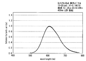
- FIG. 1 is an example of an emission spectrum of the light emitting device.
- a violet LED that emits violet light having a peak wavelength of 400 nm is used as a semiconductor light emitting device, and a basic composition represented by Sr 2.7 Eu 0.3 Si 13 Al 3 O 2 N 21 as a phosphor.
- the purple LED has a forward voltage drop Vf of 3.199 V and a forward current If of 20 mA.
- the green light emitting device using the Sr sialon green phosphor represented by the general formula (1) as the phosphor has a high emission intensity even when excitation light having a short wavelength such as violet light is used. .
- FIG. 2 is another example of an emission spectrum of the light emitting device.
- a violet LED that emits violet light having a peak wavelength of 400 nm is used as a semiconductor light emitting device, and a phosphor has a basic composition represented by Sr 1.6 Eu 0.4 Si 7 Al 3 ON 13. It is an emission spectrum of a red light emitting device at 25 ° C. using only Sr sialon red phosphor containing 1% by mass of Y together.
- the purple LED has a forward voltage drop Vf of 3.190 V and a forward current If of 20 mA.
- the red light emitting device using the Sr sialon red phosphor represented by the general formula (2) as the phosphor has a high emission intensity even when excitation light having a short wavelength such as violet light is used. .
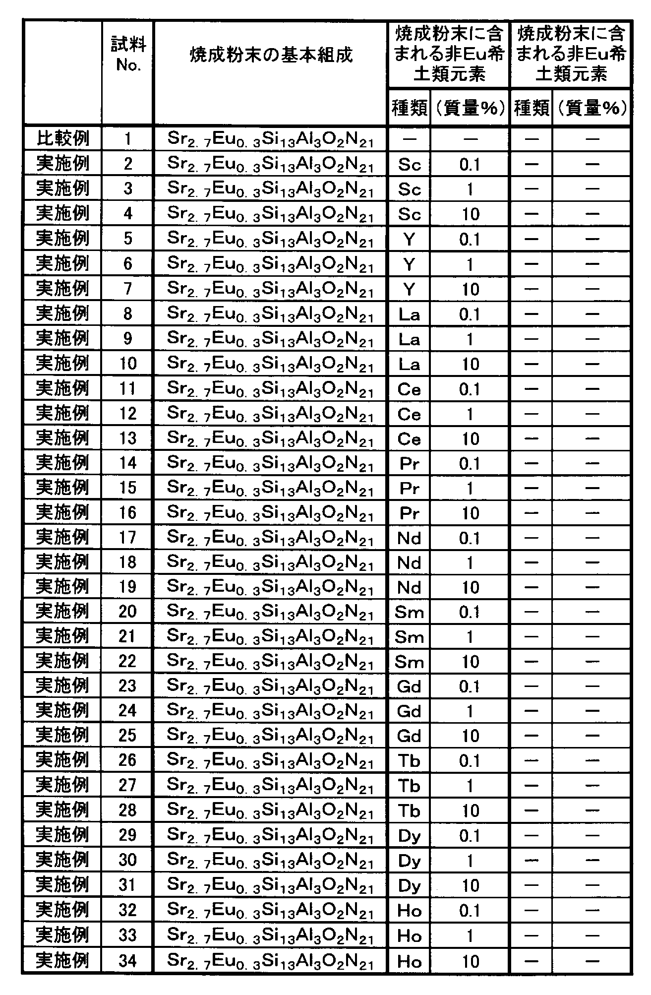
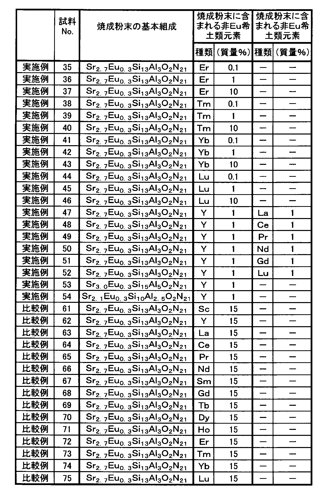
- the phosphor particles constituting the fired powder contained the types and amounts of non-Eu rare earth elements shown in Table 2.
- Sample No. In 2 the non-Eu rare earth element is Sc.
- the content (mass%) of the non-Eu rare earth element is a ratio of the mass of the non-Eu rare earth element to the mass of the entire fired powder including the non-Eu rare earth element.
- the non-Eu rare earth element was present inside each particle constituting the phosphor powder (fired powder).
- Table 2 shows the basic composition of the fired powder and the measurement results of the content of the non-Eu rare earth element contained in the fired powder.
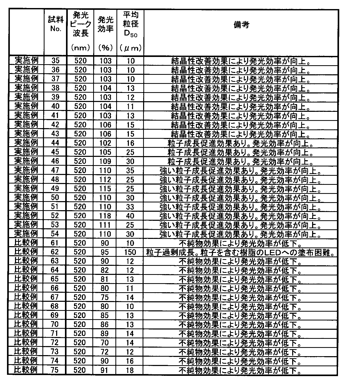
- the obtained Sr sialon phosphor was measured for emission peak wavelength, emission efficiency, and average particle size.
- the luminous efficiency is measured at room temperature (25 ° C.), and is shown as a relative value (%) where the luminous efficiency (lm / W) at room temperature of a comparative example (sample No. 1) described later is 100.
- the average particle diameter is a value measured by the Coulter counter method, the value of the median D 50 of the cumulative volume distribution. Table 3 shows the measurement results of the emission peak wavelength, the emission intensity, and the average particle diameter.
- Example No. 1 is a comparative example which does not substantially contain non-Eu rare earth elements.
- Sample No. Examples 2 to 52 are examples in which the type and content of the non-Eu rare earth element were changed.
- sample no. 53 and 54 are examples in which the basic composition represented by the general formula (1) was changed.
- No. 61 to 75 are comparative examples having a very high content of non-Eu rare earth elements.
- sample 101 is a comparative example which does not substantially contain non-Eu rare earth elements.
- Sample No. Examples 102 to 152 are examples in which the types and contents of non-Eu rare earth elements are changed.
- sample no. Reference numerals 153 and 154 are examples in which the basic composition represented by the general formula (2) is changed.
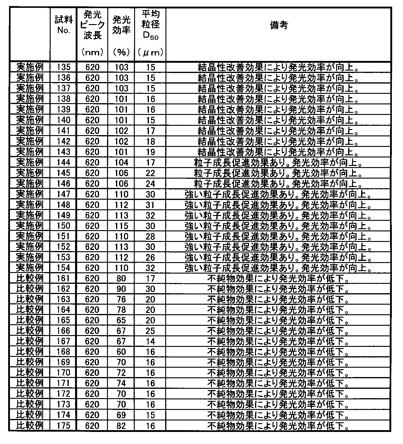
- No. 161 to 175 are comparative examples having a very high content of non-Eu rare earth elements.
- the green phosphor sample Nos In the same manner as in No. 2, the basic composition of the fired powder, the content of non-Eu rare earth elements contained in the fired powder, the emission peak wavelength, the emission intensity, and the average particle diameter were measured.
- Table 8 or Table 11 shows the basic composition of the fired powder and the measurement results of the content of non-Eu rare earth elements contained in the fired powder.
- Table 9 or Table 12 shows the measurement results of the emission peak wavelength, emission intensity, and average particle diameter.
- the phosphor when the content of the non-Eu rare earth element in the phosphor is within a specific range, the phosphor does not contain a non-Eu rare earth element or compared with a phosphor containing an excess of a non-Eu rare earth element. It can be seen that the luminous efficiency is improved.
- a phosphor and a light emitting device with high luminous efficiency can be obtained.
Landscapes
- Chemical & Material Sciences (AREA)
- Inorganic Chemistry (AREA)
- Engineering & Computer Science (AREA)
- Materials Engineering (AREA)
- Organic Chemistry (AREA)
- Luminescent Compositions (AREA)
- Led Device Packages (AREA)
Abstract
Description
従来、蛍光体としては、ストロンチウムを含むユーロピウム付活サイアロン(Si-Al-O-N)構造の蛍光体(Srサイアロン蛍光体)が知られている。
本発明は、上記事情に鑑みてなされたものであり、発光効率が高いSrサイアロン蛍光体および発光装置を提供することを目的とする。
一般式:(Sr1-x,Eux)αSiβAlγOδNω (1)
(式中、xは0<x<1、αは0<α≦4であり、β、γ、δおよびωはαが3のときに換算した数値が、9<β≦15、1≦γ≦5、0.5≦δ≦3、10≦ω≦25を満足する数である)
一般式:(Sr1-x,Eux)αSiβAlγOδNω (2)
(式中、xは0<x<1、αは0<α≦3であり、β、γ、δおよびωはαが2のときに換算した数値が、5≦β≦9、1≦γ≦5、0.5≦δ≦2、5≦ω≦15を満足する数である)
緑色蛍光体は、下記一般式(1)
一般式:(Sr1-x,Eux)αSiβAlγOδNω (1)
(式中、xは0<x<1、αは0<α≦4であり、β、γ、δおよびωはαが3のときに換算した数値が、9<β≦15、1≦γ≦5、0.5≦δ≦3、10≦ω≦25を満足する数である)
一般式(1)で表される基本組成を有するユーロピウム付活サイアロン結晶体は、斜方晶の単結晶である。ユーロピウム付活サイアロン結晶体中には、非Eu希土類元素が含まれる。
一方、Srサイアロン緑色蛍光体は、一般式(1)で表される基本組成を有するユーロピウム付活サイアロン結晶体の1個からなる結晶体、またはこのユーロピウム付活サイアロン結晶体の2個以上が凝集してなる結晶体の集合体である。
xが0であると焼成工程で得られる焼成体が蛍光体にならず、xが1であるとSrサイアロン緑色蛍光体の発光効率が低くなる。
このため、xは0<x<1のうちでも、0.025≦x≦0.5を満足する数が好ましく、0.25≦x≦0.5を満足する数がさらに好ましい。
一般式(1)において、Siの添え字であるβは、αが3のときに換算した数値が9<β≦15を満足する数である。
一般式(1)において、Alの添え字であるγは、αが3のときに換算した数値が1≦γ≦5を満足する数である。
一般式(1)において、Oの添え字であるδは、αが3のときに換算した数値が0.5≦δ≦3を満足する数である。
一般式(1)において、Nの添え字であるωは、αが3のときに換算した数値が10≦ω≦25を満足する数である。
このSrサイアロン緑色蛍光体の粉末は、平均粒径が、通常1μm以上100μm以下、好ましくは5μm以上80μm以下、さらに好ましくは8μm以上80μm以下、より好ましくは8μm以上40μm以下である。ここで、平均粒径とは、コールターカウンター法による測定値であり、体積累積分布の中央値D50を意味する。
一般式(1)で表されるSrサイアロン緑色蛍光体は、紫外光、紫色光または青色光が照射されると励起し、緑色光を出射する。
赤色蛍光体は、下記一般式(2)
一般式:(Sr1-x,Eux)αSiβAlγOδNω (2)
(式中、xは0<x<1、αは0<α≦3であり、β、γ、δおよびωはαが2のときに換算した数値が、5≦β≦9、1≦γ≦5、0.5≦δ≦2、5≦ω≦15を満足する数である)
一般式(2)で表される基本組成を有するユーロピウム付活サイアロン結晶体は、斜方晶の単結晶である。ユーロピウム付活サイアロン結晶体中には、非Eu希土類元素が含まれる。
一方、Srサイアロン赤色蛍光体は、一般式(2)で表される基本組成を有するユーロピウム付活サイアロン結晶体の1個からなる結晶体、またはこのユーロピウム付活サイアロン結晶体の2個以上が凝集してなる結晶体の集合体である。
xが0であると焼成工程で得られる焼成体が蛍光体にならず、xが1であるとSrサイアロン赤色蛍光体の発光効率が低くなる。
このため、xは0<x<1のうちでも、0.025≦x≦0.5を満足する数が好ましく、0.25≦x≦0.5を満足する数がさらに好ましい。
一般式(2)において、Siの添え字であるβは、αが2のときに換算した数値が5≦β≦9を満足する数である。
一般式(2)において、Alの添え字であるγは、αが2のときに換算した数値が1≦γ≦5を満足する数である。
一般式(2)において、Oの添え字であるδは、αが2のときに換算した数値が0.5≦δ≦2を満足する数である。
一般式(2)において、Nの添え字であるωは、αが2のときに換算した数値が5≦ω≦15を満足する数である。
このSrサイアロン赤色蛍光体の粉末は、平均粒径が、好ましくは1μm以上100μm以下、さらに好ましくは5μm以上50μm以下、より好ましくは10μm以上35μm以下である。ここで、平均粒径とは、コールターカウンター法による測定値であり、体積累積分布の中央値D50を意味する。
一般式(2)で表されるSrサイアロン赤色蛍光体は、紫外光、紫色光または青色光を受光すると励起され、赤色光を出射する。
一般式(1)で表されるSrサイアロン緑色蛍光体、および一般式(2)で表されるSrサイアロン赤色蛍光体は、たとえば、炭酸ストロンチウムSrCO3、窒化アルミニウムAlN、窒化珪素Si3N4、酸化ユーロピウムEu2O3、および非Eu希土類元素の酸化物等の各原料を乾式混合して蛍光体原料混合物を調製し、この蛍光体原料混合物を窒素雰囲気中で焼成することにより作製することができる。
蛍光体原料混合物は、耐火るつぼに充填される。耐火るつぼとしては、たとえば、窒化ホウ素るつぼ、カーボンるつぼ等が用いられる。
焼成雰囲気としては、不活性ガスが用いられる。不活性ガスとしては、たとえば、N2ガス、Arガス、N2とH2との混合ガス等が用いられる。
焼成雰囲気である不活性ガスの圧力は、通常0.1MPa(略1atm)~1.0MPa(略10atm)、好ましくは0.4MPa~0.8MPaである。
焼成温度が1400℃~2000℃の範囲内にあると、短時間の焼成で、結晶構造の欠陥の少ない高品質な単結晶の蛍光体粉末を得ることができる。
焼成時間は、通常0.5時間~20時間、好ましくは1時間~10時間、さらに好ましくは1時間~5時間、より好ましくは1.5時間~2.5時間である。
発光装置は、上記の一般式(1)で表されるSrサイアロン緑色蛍光体または一般式(2)で表されるSrサイアロン赤色蛍光体を用いる発光装置である。
具体的には、発光装置は、基板と、この基板上に配置され、紫外光、紫色光または青色光を出射する半導体発光素子と、この半導体発光素子の発光面を覆うように形成され、半導体発光素子からの出射光により励起されて可視光を発する蛍光体を含む発光部とを備え、蛍光体は、一般式(1)で表されるSrサイアロン緑色蛍光体または一般式(2)で表されるSrサイアロン赤色蛍光体を含む発光装置である。
基板としては、たとえば、アルミナ、窒化アルミニウム(AlN)等のセラミックス、ガラスエポキシ樹脂等が用いられる。基板がアルミナ板や窒化アルミニウム板であると、熱伝導性が高く、LED光源の温度上昇を抑制することができるため好ましい。
半導体発光素子は、基板上に配置される。
半導体発光素子としては、紫外光、紫色光または青色光を出射する半導体発光素子が用いられる。ここで、紫外光、紫色光または青色光とは、紫外光、紫色光または青色光の波長域内にピーク波長を有する光を意味する。紫外光、紫色光または青色光は、370nm以上470nm以下の範囲内にピーク波長を有する光であることが好ましい。
発光部は、半導体発光素子からの出射光である紫外光、紫色光または青色光により励起されて可視光を出射する蛍光体を透明樹脂硬化物中に含むものであり、半導体発光素子の発光面を被覆するように形成される。
発光部において、蛍光体は透明樹脂硬化物中に含まれる。通常、蛍光体は透明樹脂硬化物中に分散される。
蛍光体スラリーは、たとえば、100℃~160℃に加熱することにより硬化させることができる。
具体的には、半導体発光素子としてピーク波長が400nmの紫色光を出射する紫色LEDを用いるとともに、蛍光体としてSr2.7Eu0.3Si13Al3O2N21で表される基本組成を有するとともにYが1質量%含有されたSrサイアロン緑色蛍光体のみを用いた、25℃での緑色発光装置の発光スペクトルである。
なお、紫色LEDは、順方向降下電圧Vfが3.199V、順方向電流Ifが20mAである。
具体的には、半導体発光素子としてピーク波長が400nmの紫色光を出射する紫色LEDを用いるとともに、蛍光体としてSr1.6Eu0.4Si7Al3ON13で表される基本組成を有するとともにYが1質量%含有されたSrサイアロン赤色蛍光体のみを用いた、25℃での赤色発光装置の発光スペクトルである。
なお、紫色LEDは、順方向降下電圧Vfが3.190V、順方向電流Ifが20mAである。
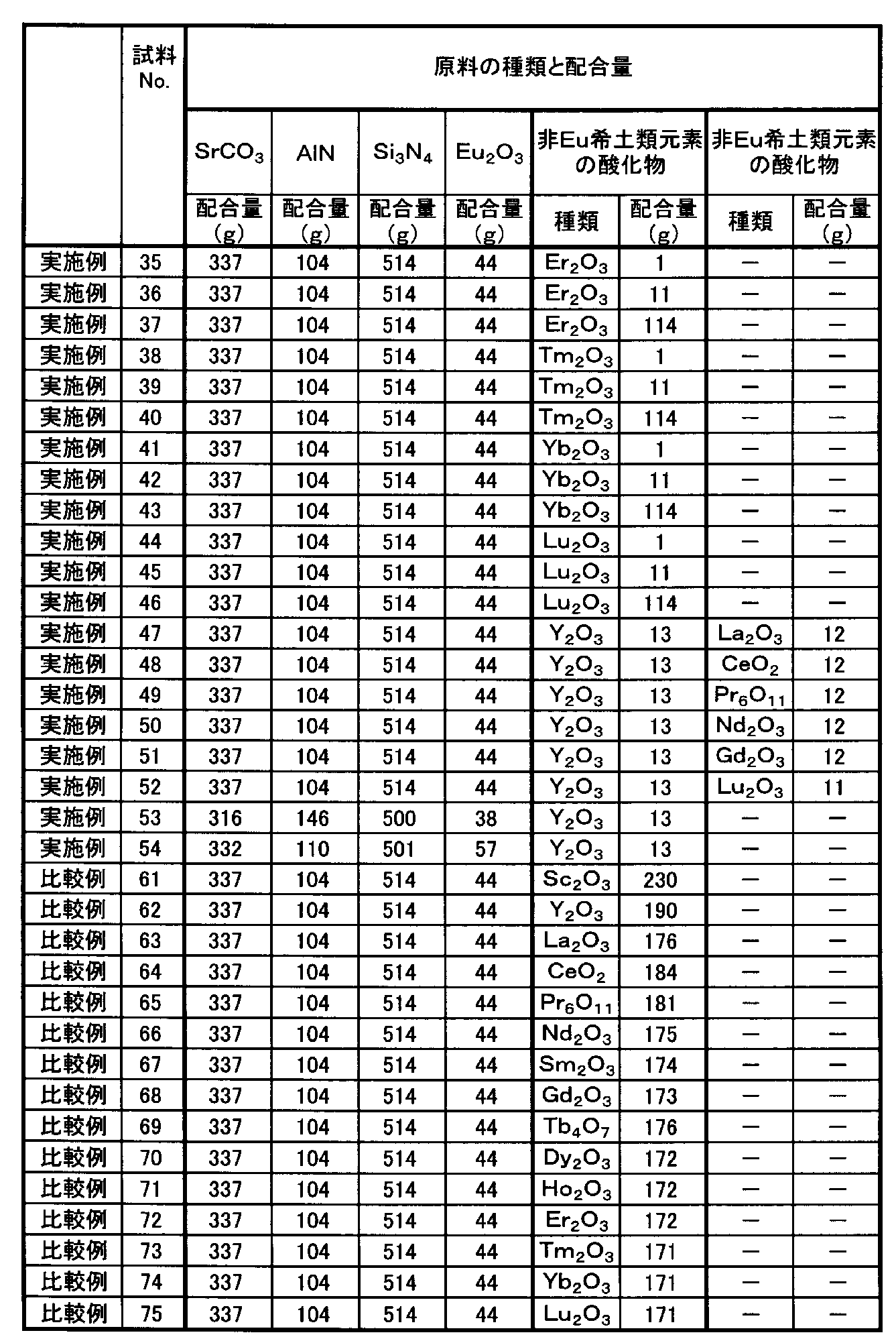
はじめに、SrCO3を337g、AlNを104g、Si3N4を514g、Eu2O3を44g、および非Eu希土類元素としてSc2O3を2g秤量し、これらにフラックス剤を適量加え、乾式混合して蛍光体原料混合物を調製した(試料No.2)。その後、この蛍光体原料混合物を窒化ホウ素るつぼに充填した。蛍光体原料混合物の原料の配合量を表1に示す。
蛍光体原料混合物が充填された窒化ホウ素るつぼを、電気炉内で、0.7MPa(略7気圧)の窒素雰囲気中、1850℃で2時間焼成したところ、るつぼ中に焼成粉末の塊が得られた。
この塊を解砕した後、焼成粉末に焼成粉末の質量の10倍量の純水を加えて10分間攪拌し、ろ過して焼成粉末を得た。この焼成粉末の洗浄操作をさらに4回繰り返し、合計5回洗浄した。洗浄後の焼成粉末をろ過し、乾燥した後、目開き45ミクロンのナイロンメッシュで篩ったところ、焼成粉末が得られた(試料No.2)。
この焼成粉末を分析したところ、表2に示す組成からなる単結晶のSrサイアロン緑色蛍光体であった。また、焼成粉末を構成する蛍光体粒子中には、表2に示す種類および量の非Eu希土類元素が含まれていた。試料No.2では、非Eu希土類元素はScである。
非Eu希土類元素の含有量(質量%)は、非Eu希土類元素を含めた焼成粉末全体の質量に対する非Eu希土類元素の質量の割合である。非Eu希土類元素は、蛍光体粉末(焼成粉末)を構成する各粒子の内部に存在していた。
焼成粉末の基本組成、および焼成粉末に含まれる非Eu希土類元素の含有量の測定結果を表2に示す。
発光効率は、室温(25℃)で測定したものであり、後述する比較例(試料No.1)の室温での発光効率(lm/W)を100とする相対値(%)として示す。
平均粒径は、コールターカウンター法による測定値であり、体積累積分布の中央値D50の値である。
発光ピーク波長、発光強度、および平均粒径の測定結果を表3に示す。
蛍光体原料混合物の原料の配合量を表1または表4に示すように変えた以外は試料No.2と同様にして、緑色蛍光体を作製した(試料No.1、No.3~54、No.61~75)。
なお、試料No.1は非Eu希土類元素を実質的に含まない比較例である。また、試料No.2~52は非Eu希土類元素の種類と含有量を変えた実施例である。さらに、試料No.53および54は一般式(1)で表される基本組成を変えた実施例である。また、No.61~75は非Eu希土類元素の含有量が非常に多い比較例である。
得られた緑色蛍光体(試料No.1、No.3~54、No.61~75)に対し、試料No.2と同様にして、焼成粉末の基本組成、焼成粉末に含まれる非Eu希土類元素の含有量、発光ピーク波長、発光強度、および平均粒径を測定した。
焼成粉末の基本組成、および焼成粉末に含まれる非Eu希土類元素の含有量の測定結果を表2または表5に示す。
発光ピーク波長、発光強度、および平均粒径の測定結果を表3または表6に示す。


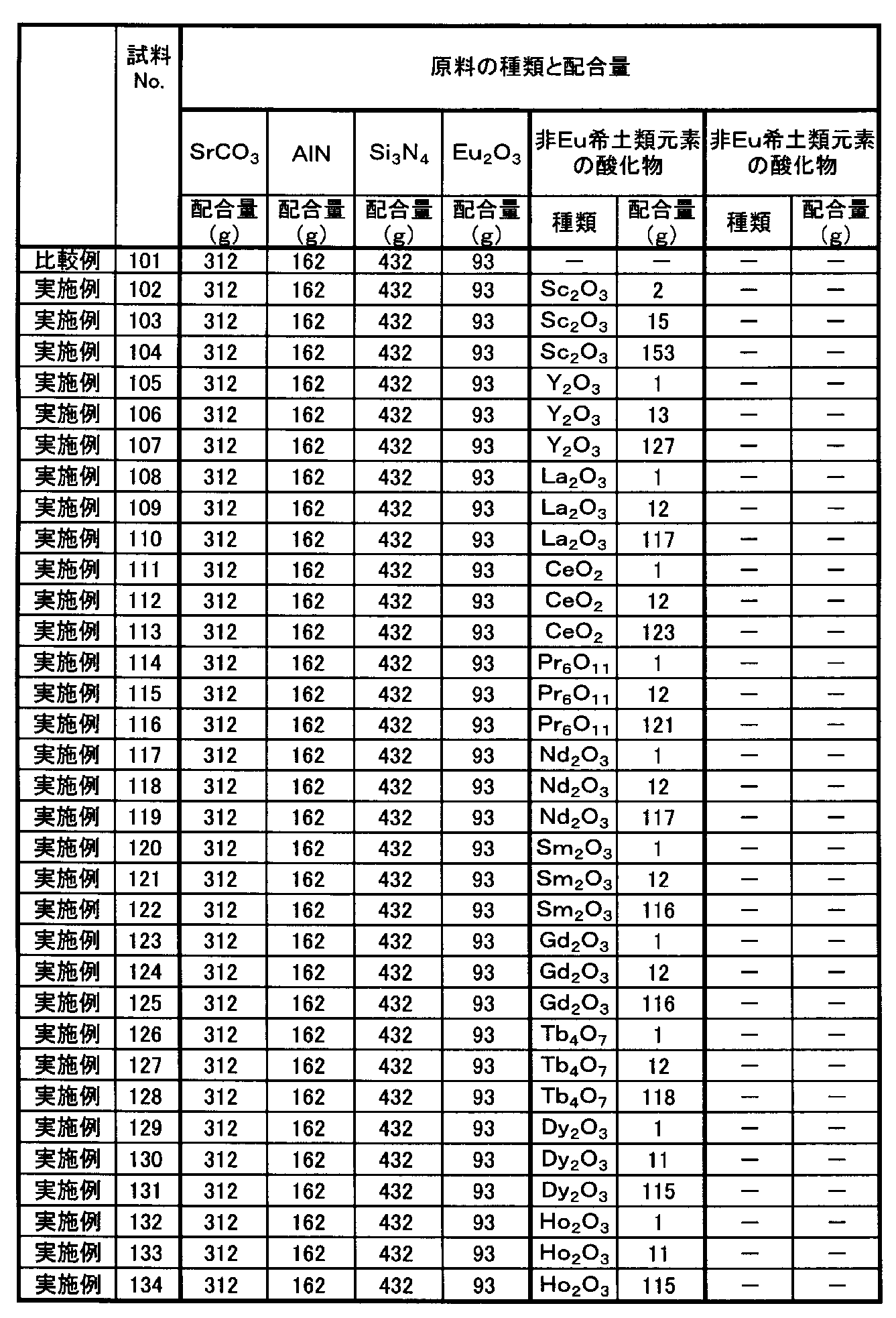
蛍光体原料混合物の原料の配合量を表7または表10に示すように変えた以外は試料No.2と同様にしたところ、焼成粉末が得られた(試料No.101~154、No.161~175)。
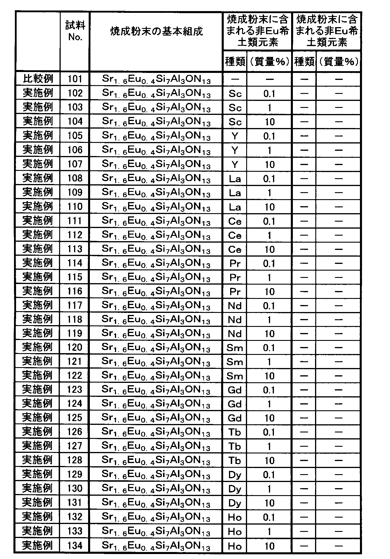
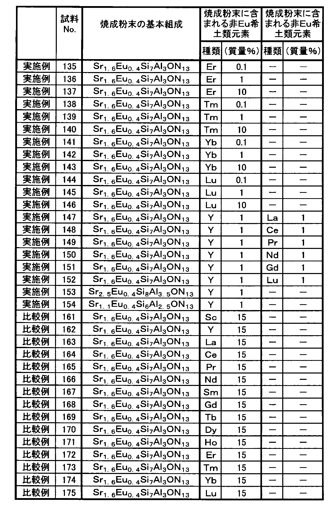
これらの焼成粉末を分析したところ、表8または表11に示す組成からなる単結晶のSrサイアロン赤色蛍光体であった。また、焼成粉末を構成する蛍光体粒子中には、表8または表11に示す種類および量の非Eu希土類元素が含まれていた。非Eu希土類元素は、蛍光体粉末(焼成粉末)を構成する各粒子の内部に存在していた。
なお、試料No.101は非Eu希土類元素を実質的に含まない比較例である。また、試料No.102~152は非Eu希土類元素の種類と含有量を変えた実施例である。さらに、試料No.153および154は一般式(2)で表される基本組成を変えた実施例である。また、No.161~175は非Eu希土類元素の含有量が非常に多い比較例である。
得られた赤色蛍光体(試料No.101~154、No.161~175)に対し、緑色蛍光体の試料No.2と同様にして、焼成粉末の基本組成、焼成粉末に含まれる非Eu希土類元素の含有量、発光ピーク波長、発光強度、および平均粒径を測定した。
焼成粉末の基本組成、および焼成粉末に含まれる非Eu希土類元素の含有量の測定結果を表8または表11に示す。
発光ピーク波長、発光強度、および平均粒径の測定結果を表9または表12に示す。


Claims (8)
- 下記一般式(1)
[化1]
一般式:(Sr1-x,Eux)αSiβAlγOδNω (1)
(式中、xは0<x<1、αは0<α≦4であり、β、γ、δおよびωはαが3のときに換算した数値が、9<β≦15、1≦γ≦5、0.5≦δ≦3、10≦ω≦25を満足する数である)
で表される基本組成を有するユーロピウム付活サイアロン結晶体からなるとともに、このサイアロン結晶体中に、Sc、Y、La、Ce、Pr、Nd、Sm、Gd、Tb、Dy、Ho、Er、Tm、YbおよびLuから選ばれる非Eu希土類元素の少なくとも1種を0.1質量%以上10質量%以下の割合で含み、
紫外光、紫色光または青色光で励起されることにより緑色発光することを特徴とする蛍光体。 - 下記一般式(2)
[化2]
一般式:(Sr1-x,Eux)αSiβAlγOδNω (2)
(式中、xは0<x<1、αは0<α≦3であり、β、γ、δおよびωはαが2のときに換算した数値が、5≦β≦9、1≦γ≦5、0.5≦δ≦2、5≦ω≦15を満足する数である)
で表される基本組成を有するユーロピウム付活サイアロン結晶体からなるとともに、このサイアロン結晶体中に、Sc、Y、La、Ce、Pr、Nd、Sm、Gd、Tb、Dy、Ho、Er、Tm、YbおよびLuから選ばれる非Eu希土類元素の少なくとも1種を0.1質量%以上10質量%以下の割合で含み、
紫外光、紫色光または青色光で励起されることにより赤色発光することを特徴とする蛍光体。 - 前記紫外光、紫色光または青色光は、370nm以上470nm以下の範囲内にピーク波長を有する光であることを特徴とする請求項1または2に記載の蛍光体。
- 平均粒径が1μm以上100μm以下であることを特徴とする請求項1~3のいずれか1項に記載の蛍光体。
- 発光ピーク波長が500nm以上540nm以下であることを特徴とする請求項1、3および4のいずれか1項に記載の緑色発光する蛍光体。
- 発光ピーク波長が550nm以上650nm以下であることを特徴とする請求項2~4のいずれか1項に記載の黄色乃至赤色発光する蛍光体。
- 基板と、
この基板上に配置され、紫外光、紫色光または青色光を出射する半導体発光素子と、
この半導体発光素子の発光面を覆うように形成され、前記半導体発光素子からの出射光により励起されて可視光を発する蛍光体を含む発光部と、を備え、
前記蛍光体は、請求項1~6のいずれか1項の蛍光体を含むことを特徴とする発光装置。 - 前記半導体発光素子は370nm以上470nm以下の範囲内にピーク波長を有する光を出射する発光ダイオードまたはレーザダイオードであることを特徴とする請求項7に記載の発光装置。
Priority Applications (4)
| Application Number | Priority Date | Filing Date | Title |
|---|---|---|---|
| US13/985,618 US20130343059A1 (en) | 2011-03-17 | 2012-02-29 | Phosphor and light emitting device |
| KR1020137024152A KR101593286B1 (ko) | 2011-03-17 | 2012-02-29 | 형광체 및 발광 장치 |
| JP2013504644A JP5955835B2 (ja) | 2011-03-17 | 2012-02-29 | 蛍光体および発光装置 |
| CN201280013746.5A CN103443243B (zh) | 2011-03-17 | 2012-02-29 | 荧光体和发光装置 |
Applications Claiming Priority (2)
| Application Number | Priority Date | Filing Date | Title |
|---|---|---|---|
| JP2011-059488 | 2011-03-17 | ||
| JP2011059488 | 2011-03-17 |
Publications (1)
| Publication Number | Publication Date |
|---|---|
| WO2012124480A1 true WO2012124480A1 (ja) | 2012-09-20 |
Family
ID=46830555
Family Applications (1)
| Application Number | Title | Priority Date | Filing Date |
|---|---|---|---|
| PCT/JP2012/055120 Ceased WO2012124480A1 (ja) | 2011-03-17 | 2012-02-29 | 蛍光体および発光装置 |
Country Status (5)
| Country | Link |
|---|---|
| US (1) | US20130343059A1 (ja) |
| JP (1) | JP5955835B2 (ja) |
| KR (1) | KR101593286B1 (ja) |
| CN (1) | CN103443243B (ja) |
| WO (1) | WO2012124480A1 (ja) |
Cited By (1)
| Publication number | Priority date | Publication date | Assignee | Title |
|---|---|---|---|---|
| US20150108521A1 (en) * | 2013-10-23 | 2015-04-23 | Kabushiki Kaisha Toshiba | Light emitting device |
Families Citing this family (1)
| Publication number | Priority date | Publication date | Assignee | Title |
|---|---|---|---|---|
| US9512359B2 (en) * | 2012-03-16 | 2016-12-06 | Kabushiki Kaisha Toshiba | Phosphor, method for producing phosphor and light emitting device |
Citations (6)
| Publication number | Priority date | Publication date | Assignee | Title |
|---|---|---|---|---|
| JP2004182781A (ja) * | 2002-11-29 | 2004-07-02 | Nichia Chem Ind Ltd | 窒化物蛍光体及びそれを用いた発光装置 |
| JP2006213910A (ja) * | 2005-01-06 | 2006-08-17 | Matsushita Electric Ind Co Ltd | 酸窒化物蛍光体及び発光装置 |
| WO2006093298A1 (ja) * | 2005-03-04 | 2006-09-08 | Dowa Electronics Materials Co., Ltd. | 蛍光体およびその製造方法、並びに当該蛍光体を用いた発光装置 |
| WO2007037059A1 (ja) * | 2005-09-27 | 2007-04-05 | Dowa Electronics Co., Ltd. | 蛍光体およびその製造方法、並びに該蛍光体を用いた発光装置 |
| JP2010106127A (ja) * | 2008-10-29 | 2010-05-13 | Toshiba Corp | 赤色蛍光体およびそれを用いた発光装置 |
| JP2010268004A (ja) * | 2010-08-18 | 2010-11-25 | Toshiba Corp | 赤色蛍光体およびそれを用いた発光装置 |
Family Cites Families (12)
| Publication number | Priority date | Publication date | Assignee | Title |
|---|---|---|---|---|
| JP3668770B2 (ja) * | 2001-06-07 | 2005-07-06 | 独立行政法人物質・材料研究機構 | 希土類元素を付活させた酸窒化物蛍光体 |
| JP2004115633A (ja) * | 2002-09-25 | 2004-04-15 | Matsushita Electric Ind Co Ltd | 珪酸塩蛍光体およびそれを用いた発光装置 |
| US7229573B2 (en) * | 2004-04-20 | 2007-06-12 | Gelcore, Llc | Ce3+ and Eu2+ doped phosphors for light generation |
| JP4674348B2 (ja) * | 2004-09-22 | 2011-04-20 | 独立行政法人物質・材料研究機構 | 蛍光体とその製造方法および発光器具 |
| CN101696353A (zh) * | 2007-08-15 | 2010-04-21 | 大连路明发光科技股份有限公司 | 含氮化合物荧光材料及其制造方法和使用其的发光装置 |
| JP5187817B2 (ja) * | 2007-10-12 | 2013-04-24 | 独立行政法人物質・材料研究機構 | 蛍光体と発光器具 |
| CN101724401A (zh) * | 2008-10-21 | 2010-06-09 | 大连路明发光科技股份有限公司 | 一种红色发光的硅氧氮化物荧光材料、制备方法及使用其的发光装置 |
| JP5326777B2 (ja) * | 2009-04-27 | 2013-10-30 | 日亜化学工業株式会社 | 蛍光体及びその製造方法 |
| JP5446493B2 (ja) * | 2009-06-15 | 2014-03-19 | 日亜化学工業株式会社 | 蛍光体及びこれを用いた発光装置 |
| JP5129392B2 (ja) * | 2009-08-28 | 2013-01-30 | 株式会社東芝 | 蛍光体の製造方法およびそれにより製造された蛍光体 |
| JP5190475B2 (ja) * | 2010-02-19 | 2013-04-24 | 株式会社東芝 | 蛍光体およびそれを用いた発光装置 |
| JP5592729B2 (ja) * | 2010-08-18 | 2014-09-17 | 株式会社東芝 | 蛍光体およびそれを用いた発光装置 |
-
2012
- 2012-02-29 JP JP2013504644A patent/JP5955835B2/ja active Active
- 2012-02-29 KR KR1020137024152A patent/KR101593286B1/ko active Active
- 2012-02-29 CN CN201280013746.5A patent/CN103443243B/zh active Active
- 2012-02-29 US US13/985,618 patent/US20130343059A1/en not_active Abandoned
- 2012-02-29 WO PCT/JP2012/055120 patent/WO2012124480A1/ja not_active Ceased
Patent Citations (6)
| Publication number | Priority date | Publication date | Assignee | Title |
|---|---|---|---|---|
| JP2004182781A (ja) * | 2002-11-29 | 2004-07-02 | Nichia Chem Ind Ltd | 窒化物蛍光体及びそれを用いた発光装置 |
| JP2006213910A (ja) * | 2005-01-06 | 2006-08-17 | Matsushita Electric Ind Co Ltd | 酸窒化物蛍光体及び発光装置 |
| WO2006093298A1 (ja) * | 2005-03-04 | 2006-09-08 | Dowa Electronics Materials Co., Ltd. | 蛍光体およびその製造方法、並びに当該蛍光体を用いた発光装置 |
| WO2007037059A1 (ja) * | 2005-09-27 | 2007-04-05 | Dowa Electronics Co., Ltd. | 蛍光体およびその製造方法、並びに該蛍光体を用いた発光装置 |
| JP2010106127A (ja) * | 2008-10-29 | 2010-05-13 | Toshiba Corp | 赤色蛍光体およびそれを用いた発光装置 |
| JP2010268004A (ja) * | 2010-08-18 | 2010-11-25 | Toshiba Corp | 赤色蛍光体およびそれを用いた発光装置 |
Cited By (2)
| Publication number | Priority date | Publication date | Assignee | Title |
|---|---|---|---|---|
| US20150108521A1 (en) * | 2013-10-23 | 2015-04-23 | Kabushiki Kaisha Toshiba | Light emitting device |
| US9349925B2 (en) * | 2013-10-23 | 2016-05-24 | Kabushiki Kaisha Toshiba | Light emitting device with oxynitride phosphors |
Also Published As
| Publication number | Publication date |
|---|---|
| JPWO2012124480A1 (ja) | 2014-07-17 |
| JP5955835B2 (ja) | 2016-07-20 |
| US20130343059A1 (en) | 2013-12-26 |
| CN103443243A (zh) | 2013-12-11 |
| KR20130129437A (ko) | 2013-11-28 |
| KR101593286B1 (ko) | 2016-02-11 |
| CN103443243B (zh) | 2015-09-09 |
Similar Documents
| Publication | Publication Date | Title |
|---|---|---|
| JP5367218B2 (ja) | 蛍光体の製造方法および発光装置の製造方法 | |
| US9331253B2 (en) | Light emitting diode (LED) component comprising a phosphor with improved excitation properties | |
| JP5713305B2 (ja) | 蛍光体、その製造方法、発光装置および画像表示装置 | |
| JP2010043242A (ja) | β−サイアロン蛍光体の製造方法。 | |
| JPWO2007099862A1 (ja) | 蛍光体とその製造方法および発光器具 | |
| KR101476561B1 (ko) | 형광체 및 발광 장치 | |
| US8440104B2 (en) | Kimzeyite garnet phosphors | |
| JP5227503B2 (ja) | 蛍光体、蛍光体シート及び蛍光体の製造方法、並びに当該蛍光体を用いた発光装置 | |
| JP2009188274A (ja) | 発光装置およびその製造方法 | |
| CN103347979B (zh) | 荧光体、其制备方法以及发光装置 | |
| JP5702568B2 (ja) | 蛍光体の製造方法および発光装置 | |
| JP5187817B2 (ja) | 蛍光体と発光器具 | |
| WO2013137436A1 (ja) | 蛍光体、蛍光体の製造方法および発光装置 | |
| JP5881176B2 (ja) | 蛍光体、照明器具および画像表示装置 | |
| JP5955835B2 (ja) | 蛍光体および発光装置 | |
| WO2013137434A1 (ja) | 蛍光体、蛍光体の製造方法および発光装置 | |
| JP7672735B2 (ja) | 蛍光体、その製造方法、発光素子および発光装置 | |
| KR20140121432A (ko) | 형광체, 형광체의 제조 방법 및 발광 장치 | |
| JP4951888B2 (ja) | 蛍光体及びそれを用いた発光装置 | |
| JP5730084B2 (ja) | ユーロピウム付活ストロンチウムサイアロン蛍光体およびその製造方法、ならびに発光装置 | |
| JP5702569B2 (ja) | 蛍光体の製造方法および発光装置 | |
| JP2017179018A (ja) | 蛍光体、その製造方法、発光装置、画像表示装置、顔料および紫外線吸収剤 | |
| JP2007321139A (ja) | 蛍光体の製造方法、蛍光体、発光素子、発光装置、画像表示装置及び照明装置 | |
| JP2017179020A (ja) | 蛍光体、その製造方法、発光装置、画像表示装置、顔料および紫外線吸収剤 | |
| JP6286676B2 (ja) | 赤色蛍光体材料および発光装置 |
Legal Events
| Date | Code | Title | Description |
|---|---|---|---|
| 121 | Ep: the epo has been informed by wipo that ep was designated in this application |
Ref document number: 12756905 Country of ref document: EP Kind code of ref document: A1 |
|
| ENP | Entry into the national phase |
Ref document number: 2013504644 Country of ref document: JP Kind code of ref document: A |
|
| WWE | Wipo information: entry into national phase |
Ref document number: 13985618 Country of ref document: US |
|
| ENP | Entry into the national phase |
Ref document number: 20137024152 Country of ref document: KR Kind code of ref document: A |
|
| NENP | Non-entry into the national phase |
Ref country code: DE |
|
| 122 | Ep: pct application non-entry in european phase |
Ref document number: 12756905 Country of ref document: EP Kind code of ref document: A1 |