WO2012121187A1 - 携帯端末装置、プログラムおよび報知制御方法 - Google Patents
携帯端末装置、プログラムおよび報知制御方法 Download PDFInfo
- Publication number
- WO2012121187A1 WO2012121187A1 PCT/JP2012/055510 JP2012055510W WO2012121187A1 WO 2012121187 A1 WO2012121187 A1 WO 2012121187A1 JP 2012055510 W JP2012055510 W JP 2012055510W WO 2012121187 A1 WO2012121187 A1 WO 2012121187A1
- Authority
- WO
- WIPO (PCT)
- Prior art keywords
- notification
- unit
- display
- terminal device
- object image
- Prior art date
- Legal status (The legal status is an assumption and is not a legal conclusion. Google has not performed a legal analysis and makes no representation as to the accuracy of the status listed.)
- Ceased
Links
Images






Classifications
-
- H—ELECTRICITY
- H04—ELECTRIC COMMUNICATION TECHNIQUE
- H04M—TELEPHONIC COMMUNICATION
- H04M1/00—Substation equipment, e.g. for use by subscribers
- H04M1/02—Constructional features of telephone sets
- H04M1/0202—Portable telephone sets, e.g. cordless phones, mobile phones or bar type handsets
- H04M1/0206—Portable telephones comprising a plurality of mechanically joined movable body parts, e.g. hinged housings
- H04M1/0208—Portable telephones comprising a plurality of mechanically joined movable body parts, e.g. hinged housings characterized by the relative motions of the body parts
- H04M1/0235—Slidable or telescopic telephones, i.e. with a relative translation movement of the body parts; Telephones using a combination of translation and other relative motions of the body parts
- H04M1/0237—Sliding mechanism with one degree of freedom
-
- G—PHYSICS
- G06—COMPUTING OR CALCULATING; COUNTING
- G06F—ELECTRIC DIGITAL DATA PROCESSING
- G06F3/00—Input arrangements for transferring data to be processed into a form capable of being handled by the computer; Output arrangements for transferring data from processing unit to output unit, e.g. interface arrangements
- G06F3/01—Input arrangements or combined input and output arrangements for interaction between user and computer
- G06F3/048—Interaction techniques based on graphical user interfaces [GUI]
- G06F3/0487—Interaction techniques based on graphical user interfaces [GUI] using specific features provided by the input device, e.g. functions controlled by the rotation of a mouse with dual sensing arrangements, or of the nature of the input device, e.g. tap gestures based on pressure sensed by a digitiser
- G06F3/0488—Interaction techniques based on graphical user interfaces [GUI] using specific features provided by the input device, e.g. functions controlled by the rotation of a mouse with dual sensing arrangements, or of the nature of the input device, e.g. tap gestures based on pressure sensed by a digitiser using a touch-screen or digitiser, e.g. input of commands through traced gestures
- G06F3/04883—Interaction techniques based on graphical user interfaces [GUI] using specific features provided by the input device, e.g. functions controlled by the rotation of a mouse with dual sensing arrangements, or of the nature of the input device, e.g. tap gestures based on pressure sensed by a digitiser using a touch-screen or digitiser, e.g. input of commands through traced gestures for inputting data by handwriting, e.g. gesture or text
-
- H—ELECTRICITY
- H04—ELECTRIC COMMUNICATION TECHNIQUE
- H04M—TELEPHONIC COMMUNICATION
- H04M2250/00—Details of telephonic subscriber devices
- H04M2250/16—Details of telephonic subscriber devices including more than one display unit
Definitions
- the present invention relates to a mobile terminal device such as a mobile phone, a PDA (Personal Digital Assistant), a tablet PC (Tablet PC), and a program and a notification control method suitable for use in the mobile terminal device.
- a mobile terminal device such as a mobile phone, a PDA (Personal Digital Assistant), a tablet PC (Tablet PC), and a program and a notification control method suitable for use in the mobile terminal device.
- a mobile terminal device such as a mobile phone is usually provided with an alarm function.
- an alarm sound is generated at a time preset by the user.
- the user can stop the alarm sound by performing a predetermined stop operation.
- the touch panel includes a display and a touch sensor arranged on the display surface of the display, and an input to the display surface is detected by the touch sensor.
- the mobile terminal device when the mobile terminal device includes a touch panel, for example, when an alarm sound is generated, a configuration in which the alarm sound stops when the touch panel is touched may be employed.
- This invention is made in view of such a subject, and it aims at providing the portable terminal device, program, and alerting
- a portable terminal device includes a display unit, a display control unit that controls the display unit, a reception unit that receives an operation on the display unit, a notification unit that performs a notification operation, and the notification A notification control unit for controlling the unit.
- the display control unit causes the display unit to display a first object image and a second object image to be operated during the notification operation.
- the notification control unit according to the moved object image, The notification operation is stopped, or the notification operation is stopped and a predetermined operation is executed.
- a program stored in a computer of a mobile terminal device that includes a display unit, a reception unit that receives an operation on the display unit, and a notification unit that performs a notification operation.
- the first object image and the second object image that are targets of the display are displayed on the display unit, and a movement operation for moving any one of the first object image and the second object image is received by the receiving unit.
- the notification operation is stopped, or the notification operation is stopped and a function of performing a predetermined operation is added.
- a third aspect of the present invention relates to a notification control method for a portable terminal device including a display unit, a reception unit that receives an operation on the display unit, and a notification unit that performs a notification operation.
- the notification control method includes a step of causing the display unit to display a first object image and a second object image to be operated during the notification operation, and a step of displaying the first object image and the second object image.
- 12 is a flowchart illustrating a processing procedure of alarm notification control according to a third modification. It is a figure which shows a screen display when alarm alerting control based on the example 3 of a change is performed.
- 10 is a flowchart showing a processing procedure of alarm notification control according to a modification example 4; It is a figure which shows a screen display when alarm alerting control based on the example 4 of a change is performed.
- the first display 11 corresponds to the “display unit” and “first display unit” recited in the claims.
- the second display 21 corresponds to a “display unit” and a “second display unit” recited in the claims.
- the first touch sensor 12 and the second touch sensor 22 correspond to the “accepting unit” recited in the claims.
- the CPU 100 corresponds to a “display control unit” and a “notification control unit” described in the claims.
- the memory 200 corresponds to a “storage unit” recited in the claims.
- the external speaker 308 corresponds to a “notification unit” described in the claims.
- the up key 28a corresponds to an “operation unit” recited in the claims.
- the cancel button B7 corresponds to the “first object image” recited in the claims.
- the snooze button B6 corresponds to the “second object image” recited in the claims.
- the message window W1 corresponds to the “image for prompting the moving operation” described in the claims.
- the magnets 14 and 23, the protrusions 16 and 17, the shaft portions 26 and 27, the coil spring 34, and the guide groove 39 constitute a “mechanism” described in the claims.
- the description of the correspondence between the claims and the present embodiment is merely an example, and the claims of the present invention are not limited to the present embodiment.
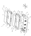
- FIG. 1 is an exploded perspective view showing the configuration of the mobile phone 1.
- the mobile phone 1 includes a first cabinet 10, a second cabinet 20, and a holding body 30 that holds the first cabinet 10 and the second cabinet 20.
- the first cabinet 10 has a horizontally long rectangular parallelepiped shape.
- the first cabinet 10 is provided with a first touch panel TP1.
- the first touch panel TP1 includes a first display 11 and a first touch sensor 12.
- the surface of the first touch panel TP1 is covered with a protective cover.
- the first display 11 includes a first liquid crystal panel 11a and a first backlight 11b that illuminates the first liquid crystal panel 11a (see FIG. 3).
- a first display surface 11c is provided on the front surface of the first liquid crystal panel 11a, and an image (screen) is displayed on the first display surface 11c.
- the first backlight 11b includes one or more light sources.
- a first touch sensor 12 is placed on the first display 11 so as to overlap.
- the first touch sensor 12 detects an input to the first display 11.
- the first touch sensor 12 is a transparent rectangular sheet and covers the first display surface 11 c of the first display 11.
- the first touch sensor 12 includes a first transparent electrode and a second transparent electrode arranged in a matrix.
- the first touch sensor 12 detects a change in capacitance between the transparent electrodes, thereby detecting a position on the first display surface 11c touched by the user, and outputs a position signal corresponding to the position.
- the user touches the first display surface 11c for example, the user not only touches the contact member such as a pen or a finger completely on the first display surface 11c, but also the first display surface 11c. 11c proximity is also included.
- the user can perform various operations such as “tap”, “slide”, “flick”, and “long tap” on the first display surface 11c by touching the first display surface 11c with a finger or the like. it can.
- the “tap” is an operation in which the user taps the display surface with a contact member or a finger. That is, the user refers to an operation of releasing a contact member or a finger from the display surface in a short time after contacting the display surface with a contact member or a finger.
- “Slide” refers to an operation in which a user moves a contact member or a finger while keeping it in contact with the display surface.
- “Flick” is an operation in which the user quickly flips the display surface with a contact member or a finger. That is, the user refers to an operation of moving a contact member or a finger over a predetermined distance in a short time while touching the display surface.
- “Long tap” refers to an operation in which the user keeps the same position on the display surface in contact with a contact member or a finger for a predetermined time (a longer time than the tap) or longer.
- Operations that the user touches the display surface including operations such as “tap”, “slide”, “flick”, and “long tap” are collectively referred to as “touch”.
- an operation for moving the touched object image by touching an object image to be operated such as an icon, a snooze button and a release button, which will be described later, displayed on the display surface, and sliding the finger. Is called “drag”.
- a camera module 13 is arranged at a slightly rear position in the center.
- a lens window for capturing a subject image in the camera module 13 is provided on the lower surface of the first cabinet 10.
- a magnet 14 is disposed at the center position near the front surface, and a magnet 15 is disposed at the right front corner.
- protrusions 16 and 17 are provided on the right side surface and the left side surface of the first cabinet 10.
- the second cabinet 20 has a horizontally long rectangular parallelepiped shape and has substantially the same shape and size as the first cabinet 10.
- the second cabinet 20 is provided with a second touch panel TP2.
- the second touch panel TP2 includes a second display 21 and a second touch sensor 22.
- the surface of the second touch panel TP2 is covered with a protective cover.
- the second display 21 includes a second liquid crystal panel 21a and a second backlight 21b that illuminates the second liquid crystal panel 21a (see FIG. 3).
- a second display surface 21c is provided on the front surface of the second liquid crystal panel 21a, and an image (screen) is displayed on the second display surface 21c.
- the second backlight 21b includes one or more light sources.
- a second touch sensor 22 is placed on the second display 21 so as to overlap.
- the first display 11 and the second display 21 may be composed of other display elements such as an organic EL.
- the second touch sensor 22 detects an input to the second display 21.
- the configuration of the second touch sensor 22 is the same as that of the first touch sensor 12.
- the user can perform various operations such as “tap”, “slide”, “flick”, and “long tap” on the second display surface 21c by touching the second display surface 21c with a finger or the like. it can.
- a magnet 23 is arranged at a central position near the rear surface.
- the magnet 23 and the magnet 14 of the first cabinet 10 attract each other in the open state described later.
- a closing sensor 24 is disposed at the right front corner, and an opening sensor 25 is disposed at the right rear corner.
- the closing sensor 24 and the opening sensor 25 are configured by, for example, a Hall IC, and output a detection signal in response to the magnetic force of the magnet 15.
- the magnet 15 of the first cabinet 10 approaches the closing sensor 24, so that an ON signal is output from the closing sensor 24.
- the closed state is changed to the open state, the magnet 15 of the first cabinet 10 approaches the open sensor 25, so that an ON signal is output from the open sensor 25.
- the volume key 28 includes an up key 28a for increasing the volume and a down key 28b for decreasing the volume.
- the holding body 30 includes a bottom plate portion 31, a right holding portion 32 formed at the right end portion of the bottom plate portion 31, and a left holding portion 33 formed at the left end portion of the bottom plate portion 31.
- the bottom plate portion 31 is provided with three coil springs 34 arranged in the left-right direction. These coil springs 34 abut against the lower surface of the second cabinet 20 in a state in which the second cabinet 20 is attached to the holding body 30, and exert a force for pushing the second cabinet 20 upward.
- a microphone 35 (hereinafter referred to as “microphone”) and a power key 36 are arranged on the upper surface of the right holding portion 32.
- a speaker 38 is disposed on the upper surface of the left holding portion 33.
- a plurality of operation keys 37 as hard keys are arranged on the outer surface of the right holding part 32.
- a guide groove 39 (shown only on the left holding portion 33 side) is formed on the inner surfaces of the right holding portion 32 and the left holding portion 33.
- the guide groove 39 includes an upper groove 39a, a lower groove 39b, and two vertical grooves 39c.
- the upper groove 39a and the lower groove 39b extend in the front-rear direction, and the vertical groove 39c extends vertically so as to connect the upper groove 39a and the lower groove 39b.
- the shaft portions 26 and 27 are inserted into the lower groove 39 b of the guide groove 39, and the second cabinet 20 is disposed in the accommodation region R of the holding body 30.
- the protrusions 16 and 17 are inserted into the upper groove 39 a of the guide groove 39, and the first cabinet 10 is accommodated in the accommodation region R of the holding body 30.
- the first cabinet 10 is disposed on the second cabinet 20.
- the first cabinet 10 and the second cabinet 20 are accommodated in the accommodation region R surrounded by the bottom plate part 31, the right holding part 32, and the left holding part 33 in a state where they overlap each other.
- the first cabinet 10 can slide back and forth along the upper groove 39a.
- the second cabinet 20 can slide back and forth along the lower groove 39b.
- the second cabinet 20 moves forward and the shaft portions 26 and 27 reach the position of the vertical groove 39c, the second cabinet 20 is guided by the vertical groove 39c and can slide up and down.
- FIGS. 2A to 2D are diagrams for explaining an operation for switching the mobile phone 1 from the closed state to the open state.
- the closed state corresponds to the first form of the present invention
- the open state corresponds to the second form of the present invention.
- the closed state shown in FIG. 2A is a state in which the mobile phone 1 is folded.
- the first cabinet 10 is stacked on the second cabinet 20.
- the second display surface 21c is hidden by the first cabinet 10, and only the first display surface 11c is exposed to the outside.
- the first cabinet 10 is moved backward, and as shown in FIG. 2C, the second cabinet 20 is moved forward.
- the shaft portions 26 and 27 shown in FIG. 1 reach the position of the vertical groove 39c. Since the shaft portions 26 and 27 can move along the vertical groove 39c, the second cabinet 20 can move up and down.
- the second cabinet 20 is raised by the elastic force of the coil spring 34 and the attractive force of the magnet 14 and the magnet 23.
- the second cabinet 20 is arranged in close contact with the first cabinet 10, and the second display surface 21c of the second cabinet 20 is at the same height as the first display surface 11c.
- the mobile phone 1 is switched to the open state.
- the first cabinet 10 and the second cabinet 20 are arranged in the front-rear direction, and both the first display surface 11c and the second display surface 21c are exposed to the outside.
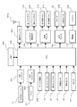
- FIG. 3 is a block diagram showing the overall configuration of the mobile phone 1.
- the mobile phone 1 includes a CPU 100, a memory 200, a video encoder 301, an audio encoder 302, a key input circuit 303, a communication module 304, a backlight drive circuit 305, a video decoder 306, in addition to the above-described components.
- An audio decoder 307, an external speaker 308, a battery 309, a power supply unit 310, and a clock 311 are provided.
- the camera module 13 has an image sensor such as a CCD.
- the camera module 13 digitizes the image signal output from the image sensor, performs various corrections such as gamma correction on the image signal, and outputs the image signal to the video encoder 301.
- the video encoder 301 encodes the imaging signal from the camera module 13 and outputs the encoded signal to the CPU 100.
- the microphone 35 converts the collected sound into a sound signal and outputs the sound signal to the sound encoder 302.
- the audio encoder 302 converts an analog audio signal from the microphone 35 into a digital audio signal, encodes the digital audio signal, and outputs it to the CPU 100.
- the key input circuit 303 outputs an input signal corresponding to each key to the CPU 100 when the power key 36, the operation key 37 or the volume key 28 is pressed.
- the communication module 304 converts various data (audio data, image data, etc.) from the CPU 100 into a radio signal and transmits it to the base station via the antenna 304a. Further, the communication module 304 converts a radio signal received via the antenna 304a into various data and outputs the data to the CPU 100.
- the backlight drive circuit 305 supplies a drive signal corresponding to a control signal from the CPU 100 to the first backlight 11b and the second backlight 21b.
- the first backlight 11b is turned on by a drive signal from the backlight drive circuit 305 and illuminates the first liquid crystal panel 11a.
- the second backlight 21b is turned on by a drive signal from the backlight drive circuit 305 and illuminates the second liquid crystal panel 21a.
- the video decoder 306 converts the image data from the CPU 100 into image signals that can be displayed on the first liquid crystal panel 11a and the second liquid crystal panel 21a, and outputs them to the liquid crystal panels 11a and 21a.
- the first liquid crystal panel 11a displays an image corresponding to the image signal on the first display surface 11c.
- the second liquid crystal panel 21a displays an image corresponding to the image signal on the second display surface 21c.
- the audio decoder 307 decodes the audio signal from the CPU 100 and the sound signals of various notification sounds such as ringtones and alarm sounds, and further converts them into analog audio signals and sound signals.
- the speaker 38 reproduces the audio signal from the audio decoder 307 as audio.
- the external speaker 308 reproduces the sound signal from the audio decoder 307 as a notification sound.
- the battery 309 supplies power to the CPU 100 and other parts than the CPU 100.
- the battery 309 is connected to the power supply unit 310.
- the power supply unit 310 converts the voltage of the battery 309 into a voltage having a necessary magnitude for each unit and supplies the voltage to each unit. Further, the power supply unit 310 supplies power supplied via an external power supply (not shown) to the battery 309 to charge the battery 309.
- the clock 311 measures time and outputs a signal corresponding to the measured time to the CPU 100.
- the memory 200 includes a ROM and a RAM.
- the memory 200 stores a control program for giving a control function to the CPU 100.
- the control program includes an application program (hereinafter simply referred to as “application”) for alarm notification at an alarm time, which will be described later.
- application an application program
- the control program includes various applications such as a call application, a mail application, and a web browser.
- the memory 200 stores image data captured by the camera module 13, various data captured from the outside via the communication module 304, and the like in a predetermined file format.
- the CPU 100 is based on operation input signals from the key input circuit 303 and the touch sensors 12 and 22, and according to the control program, the camera module 13, the microphone 35, the communication module 304, the liquid crystal panels 11a and 21a, the call speaker 38, the external speaker 308, and the like. To work. In this way, various applications are executed.
- the CPU 100 generates launcher screens and execution screens for various applications in the work area prepared in the memory 200, and outputs video signals for displaying these screens to the displays 11 and 21, respectively.
- the CPU 100 determines what operation is performed on the display surfaces 11c and 21c based on the detection results of the touch sensors 12 and 22. For example, if the time when the input to the display surfaces 11c and 21c is detected is shorter than a predetermined specified time and the input position does not move, the CPU 100 determines that a tap operation has been performed on the display surfaces 11c and 21c. To do. When the input position moves, the CPU 100 determines that a slide operation has been performed on the display surfaces 11c and 21c. When the first input position is a display position of a snooze button B6 and a release button B7, which will be described later, and the input position is determined to be a slide operation from that position, the CPU 100 selects these buttons B6 and B7.
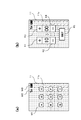
- FIG. 4A is a diagram showing a state in which a launcher screen is displayed on the first display surface 11c in a state where the mobile phone 1 is closed.
- FIG. 4B is a diagram showing a state in which an alarm time setting screen is displayed on the first display surface 11c in a state in which the mobile phone 1 is closed.
- the screen is displayed on the first display surface 11c so that the left-right direction of the mobile phone 1 (see FIG. 1) is the vertical direction of the screen.
- icons M1 corresponding to various applications are displayed on the launcher screen.
- the application can be obtained by downloading through the Internet in addition to the application provided in advance in the mobile phone 1, and the obtained application is added to the mobile phone 1 by installation.
- an antenna mark M2 indicating the reception state and a remaining amount mark M3 indicating the remaining amount of the battery 309 are displayed.
- the user can confirm the reception state by the antenna mark M2, and can confirm the remaining amount of the battery 309 by the remaining amount mark M3.
- the user can start a desired application by tapping the desired icon M1 with a finger or the like from among the plurality of icons M1.
- the memory 200 stores an icon correspondence table that associates each icon M1 with the position of each icon M1 on the display surfaces 11c and 21c, and an application correspondence table that associates each icon M1 with each application.
- the CPU 100 specifies the tapped icon M1 using the icon correspondence table based on the tapped position.
- the application correspondence table the application corresponding to the tapped icon M1 is specified, and the application is activated.
- an execution screen related to the application is displayed on the first display surface 11c. For example, when the web browser is activated, a web page based on the URL is displayed on the first display surface 11c.
- the CPU 100 activates the alarm application.
- the user sets an alarm notification time (hereinafter referred to as “alarm time”) on the setting screen shown in FIG.
- alarm time an alarm notification time
- a set button B5 for confirming time are displayed.
- the CPU 100 causes the memory 200 to store the set time.
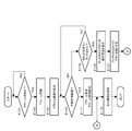
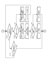
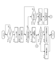
- 5 and 6 are flowcharts showing the processing procedure of the alarm notification control.
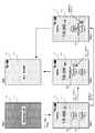
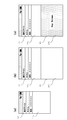
- 7 and 8 are diagrams showing transition states of screen display when the alarm notification control is executed in a state where the mobile phone 1 is closed.
- FIG. 9 is a diagram showing a screen display when an alarm is activated in a state where the mobile phone 1 is opened.
- CPU 100 monitors whether or not the alarm time is reached based on the time measured by clock 311 (S101).
- the CPU 100 determines that the alarm time has come (S101: YES), it activates the alarm (S102). That is, the CPU 100 outputs a sound signal for a predetermined alarm sound to the external speaker 308. As a result, a predetermined alarm sound is emitted from the external speaker 308.
- the CPU 100 generates an alarm screen, and if the mobile phone 1 is closed, as shown in (Screen 2) of FIG. 7, the generated alarm screen is displayed on the first display surface 11c (S103).
- a snooze button B6 and a release button B7 are displayed along with the time. These buttons B6 and B7 have different color tones.
- an alarm screen is displayed on one display surface, for example, the second display surface 21c, as shown in FIG.
- the screen displayed before the alarm is activated is continuously displayed on the other display surface.
- the same alarm screen may be displayed on both display surfaces 11c and 21c, or one alarm screen may be displayed on a large display surface that is a combination of both display surfaces 11c and 21c.
- the CPU 100 determines whether or not a predetermined alarm operating time (for example, 10 minutes) has elapsed (S104), and if not (S104: NO), the snooze button B6 and the release button It is monitored whether any button of B7 is touched (S105).
- a predetermined alarm operating time for example, 10 minutes
- a predetermined waiting time for example, 5 minutes
- the CPU 100 displays a button operation method around the touched button (S106). Further, the CPU 100 darkens the button by adjusting the color tone of the button that has not been touched (S107). For example, when the snooze button B6 is touched, as shown in FIG. 7 (screen 3), the word “Flick to Snooze” prompting the flick operation is displayed above the snooze button B6, and the release button B7 Becomes darker. On the other hand, when the release button B7 is touched, as shown in FIG. 7 (screen 4), the word “Flick to Dismiss” prompting the flick operation is displayed above the release button B7, and the snooze button B6. Becomes darker. With such a display, the user can clearly grasp the button to be operated and the operation method thereof.
- the CPU 100 monitors whether or not an operation for moving the touched button has been performed, that is, whether or not an input to the display position of the button has been detected and the input position has moved (S108). . If there is such a moving operation (S108: YES), the CPU 100 determines whether or not the moving operation is a confirmed flick (S109). If the movement operation is a confirmed flick (S109: YES), the CPU 100 displays the flicked button in the flicked direction by a distance corresponding to the strength of the flick (S110: screen of FIG. 7). 3 and 4). At this time, as the movement distance of the input position within the unit time is equal to or greater than the first specified distance and the distance is larger, it is determined that the flick is stronger and the button is moved more greatly.
- the CPU 100 stops the alarm (S111). That is, the CPU 100 stops outputting the sound signal to the external speaker 308 and stops the alarm sound. Further, the CPU 100 stops measuring the operation time (S111). If the operated button is the snooze button B6 (S112: YES), the CPU 100 performs snooze setting (S113). If the operated button is the release button B7 (S112: NO), the CPU 100 performs alarm cancel setting (S114).
- the CPU 100 returns the alarm screen displayed on the first display surface 11c (second display surface 21c) to the screen before the alarm is activated as shown in (screen 5) of FIG. 7 (S118). .
- the alarm is activated in the standby state as shown in (Screen 1) of FIG. 7, the screen immediately before entering the standby state is displayed as the screen before the alarm is activated.
- the CPU 100 terminates the alarm application, so that the alarm does not operate again thereafter.
- the alarm application is not terminated, and the time when the standby time elapses from the alarm stop becomes the new alarm time.
- the CPU 100 again monitors whether or not the alarm time has come in step S101.
- the CPU 100 determines that the alarm time has come (S101: YES), and activates the alarm again.
- step S109 it is determined that the moving operation is not a confirmed flick (S109: NO).
- the CPU 100 determines the direction of the moving operation according to the strength of the moving operation, that is, according to the moving distance of the input position within the unit time.
- the button is moved once, the button is returned to the original position (S115).
- the CPU 100 displays the message window W1 on the alarm screen for a predetermined time (for example, 2 seconds) (S116). For example, as shown in FIG. 8 (screen 3), a message window W1 is displayed that includes words such as “Flick harder to operate” that prompts the user to flick strongly.
- the user may not perform any operation while the alarm is activated.
- the user touches any one of the buttons B6 and B7, but the subsequent operation is not performed.
- the CPU 100 stops the alarm and performs an alarm release setting (S117). Thereafter, the CPU 100 returns the alarm screen displayed on the first display surface 11c (second display surface 21c) to the screen before the alarm is activated (S118).
- the snooze button B6 and the release button B7 are displayed on the first display surface 11c (second display surface 21c) during the notification operation using the alarm sound, and any one of the buttons B6 and B7 is displayed.
- the notification operation is stopped. Therefore, even if an object or the like touches the first display surface 11c (second display surface 21c) by mistake, the notification operation is not stopped unless the buttons B6 and B7 are touched. Operation is difficult to stop.
- the notification operation is not stopped unless a predetermined movement operation, that is, a confirmation flick is performed on the snooze button B6 or the release button B7. Therefore, the notification operation is not stopped only by touching the snooze button B6 or the release button B7 with an object or the like, so that the notification operation is more unlikely to be erroneously stopped.
- the operated button moves in the direction of the movement operation. Therefore, it is easy for the user to understand that the button has been operated.
- the user's movement operation is not a confirmed flick
- a message prompting the correct operation is displayed on the first display surface 11c (second display surface 21c). Therefore, the user can easily grasp that the correct operation has not been performed.
- the button when the snooze button B6 or the release button B7 is touched, the button is selected, and the notification operation is stopped only after the button is operated. Therefore, the notification operation is more unlikely to be erroneously stopped.
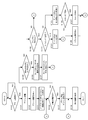
- FIG. 10 is a flowchart illustrating a processing procedure of alarm notification control according to the first modification.
- FIGS. 11A to 11C are diagrams showing transition states of the screen display when the alarm notification control is executed in the state where the mobile phone 1 is closed.
- the up key 28a of the volume key 28 is used as a hard key.
- steps S121 to S128 are added to the alarm notification control of the embodiment shown in FIG.
- the other processes are the same as those in the above embodiment.
- CPU 100 determines that the vicinity of up key 28a, as shown in (screen 1) of FIGS. 11 (a), 11 (b), and 11 (c).
- Marks D1, D2 and D3 indicating the function to which the up key 28a is assigned are displayed at a position on the alarm screen.
- the user selects one of the three functions “silence”, “snooze”, and “alarm release” by performing a predetermined setting operation in advance, and sets the selected function as a function that can be executed by operating the up key 28a. it can. For example, if the “silence” function is set, a mark D1 corresponding to the “silence” function is displayed as shown in FIG.
- a mark D2 corresponding to the “snooze” function is displayed as shown in FIG.
- a mark D3 corresponding to the “alarm release” function is displayed as shown in FIG.
- the user can also perform a setting operation for setting so that none of the three functions is executed. In this case, the marks D1, D2, and D3 are not displayed, and the operation on the up key 28a is invalidated.
- the CPU 100 monitors whether the snooze button B6 or the release button B7 is touched while the alarm is activated (S106) and monitors whether the up key 28a is pressed (S122).
- the CPU 100 stops the alarm and turns off the mark D1 if the “silence” function is set (S123: YES) (S124). As shown in (screen 2) of FIG. 11A, the mark D1 disappears from the alarm screen, but the alarm screen itself continues to be displayed. At this time, the measurement of the operation time is continued, and the process returns to step S104.
- step S118 is executed, and a screen before the alarm is activated is displayed on the first display surface 11c as shown in (screen 2) of FIGS. 11 (b) and 11 (c).
- the “silence” function is set in advance, the user can stop only the alarm sound by pressing the up key 28a. Furthermore, if the “snooze” function is set in advance, the user can stop the alarm sound by pressing the up key 28a without operating the snooze button B6, and a predetermined waiting time. After the elapse, the alarm can be activated again. Further, if the “alarm release” function is set in advance, the user can stop the alarm sound by pressing the up key 28a without operating the release button B7, and can set the alarm. Can be canceled.
- an alarm sound can be generated without operating the display surfaces 11c and 21c by operating a hard key (up key 28a) provided at a position different from the display surfaces 11c and 21c.
- the notification operation can be stopped. Further, the notification operation can be stopped by a single operation of the up key 28a, and the operation becomes easy.
- the hard key for stopping the notification operation is arranged near the display surfaces 11c and 21c, and the marks D1 and D2 near the hard key are arranged on the display surfaces 11c and 21c. , D3 is displayed. Therefore, it is easy for the user to understand that the hard key can be used.
- the operation on the display surfaces 11c and 21c (touch sensors 12 and 22) only needs to touch the display surfaces 11c and 21c, almost no force is required to push the display surfaces 11c and 21c.
- the operation on the up key 28a requires a larger pressing force than the operation on the display surfaces 11c and 21c. Therefore, even if an object hits the up key 28a, it is difficult to accept the operation.
- the alarm is stopped when a final flick is performed on the selected button after any of the snooze button B6 and the release button B7 is selected by the user's tap.
- the operation for stopping the alarm for the snooze button B6 or the release button B7 may be replaced with a drag beyond a predetermined distance instead of a confirmed flick.
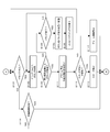
- FIG. 12 is a flowchart showing a processing procedure of alarm notification control according to the second modification.
- step S131 the CPU 100 determines whether or not the previously tapped button has been dragged. If the button is dragged by the user (S131: YES), the CPU 100 moves the button in response to the drag (S132). That is, the CPU 100 displays buttons so as to follow the movement of the input position with respect to the first display surface 11c (second display surface 21c). As in (Screen 3) and (Screen 4) in FIG. 7, the button moves on the first display surface 11c (second display surface 21c).
- the CPU 100 stops the alarm and the measurement of the operation time (S111). Thereafter, processing is executed in the same manner as in the above embodiment.
- the CPU 100 moves the button to the position before the dragging as in (Screen 2) of FIG. (S135). After that, the CPU 100 displays the message window W1 on the alarm screen for a predetermined time (for example, 2 seconds) as in (Screen 3) of FIG. 8 (S136).
- the message window W1 is configured with a word that prompts a drag longer than the previous drag.
- the notification operation is not easily stopped unintentionally and unintentionally by the user, as in the above embodiment.
- the alarm is stopped when a drag of a predetermined distance or more is made, but the alarm is generated regardless of whether the confirmed flick or the drag of a predetermined distance or more is performed. It may be configured to be stopped. Furthermore, the configuration of this modification example may be applied to the configuration of the modification example 1.
- the alarm is stopped when the snooze button B6 or the release button B7 is dragged more than a predetermined distance.
- the snooze button B6 or the release button B7 displayed on one display surface 11c, 21c is dragged to the other display surface 11c, 21c. Then, the alarm may be stopped.
- FIG. 13 is a flowchart showing a processing procedure of alarm notification control according to the third modification.
- FIG. 14 is a diagram illustrating a screen display when the alarm notification control is executed.
- the CPU 100 determines that the previously tapped button has been dragged (S141: YES). Then, the CPU 100 determines whether or not the dragged button has been moved to the other display surface (S143).
- the CPU100 will move a button to the position before drag
- the notification operation is not easily stopped unintentionally and unintentionally by the user, as in the above embodiment.
- FIG. 15 is a flowchart showing a processing procedure of alarm notification control according to the fourth modification.
- FIGS. 16A to 16C are diagrams showing screen displays when the alarm notification control is executed.
- the CPU 100 sets a predetermined application in relation to the alarm. It is determined whether or not (S151).
- a selection screen for selecting an application is displayed.
- application items such as mail, address book, and web browser are displayed on the selection screen, and when a desired application is selected by the user, the application is set as an application related to an alarm.
- the set application is stored in the memory 200.
- the CPU 100 activates the application and displays the execution screen of the application on the first display surface 11c (second display surface 21c) (S152). ). For example, if a mail application is set and the mobile phone 1 is closed, as shown in FIG. 16A, a predetermined execution screen for the mail application on the first display surface 11c, for example, mail creation A screen is displayed. If a mail application is set and the mobile phone 1 is open, a mail creation screen is displayed on the first display surface 11c and the second display surface 21c as shown in FIG. Alternatively, when the mobile phone 1 is open, as shown in FIG.
- the mail creation screen is displayed on one display surface, and the screen displayed before the alarm is activated is displayed on the other display surface.
- the user may be able to set in advance whether the display form of FIG. 16B or the display form of FIG.
- a preset destination (address) may be automatically displayed on the mail creation screen.
- a preset website screen may be displayed.
- information on a preset partner (phone number, address, etc.) may be displayed.
- notification is performed by an alarm sound from the external speaker 308.
- the notification operation is not limited to the notification operation using an alarm sound.
- the mobile phone 1 may be provided with a vibrator and may be notified by vibration of the vibrator.
- notification may be performed by both alarm sound and vibration.
- a configuration may be adopted in which the user can set whether the alarm sound is turned on or off, or whether the vibration is turned on or off.
- the message window W1 when the movement operation for the snooze button B6 or the release button B7 is not a confirmed flick, the message window W1 is displayed.
- the message window W1 is not necessarily displayed. Instead of the message window W1, or together with the message window W1, a notification sound may be generated indicating that the operation on the buttons B6 and B7 has not been accepted.
- the snooze button B6 or the release button B7 is selected by touching any button.
- the present invention is not limited to this, and a button may be selected by a specific touch operation such as a tap or a long tap.
- ⁇ There may be incoming calls or emails during alarm notification.
- the alarm is stopped, and an incoming call notification using a ring tone is performed instead.
- the display on the first display surface 11c (second display surface 21c) is switched from the alarm screen to an incoming call notification screen including incoming information such as a telephone number.
- the alarm is stopped, and instead, a low battery notification is performed to notify that the remaining battery level is low by a beep sound.
- the display on the first display surface 11c (second display surface 21c) is switched from the alarm screen to a notification screen informing that the remaining battery level is low.
- an alarm screen is displayed again on the first display surface 11c (second display surface 21c) and an alarm is activated.
- the snooze button B6 or the release button B7 is selected before the incoming call notification or the low battery notification is made, and the operation method is displayed and the selected button is darkened on the alarm screen.
- the alarm screen in that state is displayed again.
- both the snooze button B6 and the release button B7 are displayed on the alarm screen, but only one of the buttons may be displayed. Further, a mute button for stopping only the alarm sound may be displayed instead of at least one of these buttons B6 and B7 or in addition to these buttons B6 and B7.
- the CPU 100 stops the alarm but does not stop the operation time and keeps the alarm screen displayed.
- the mobile phone 1 may be closed by the user when an alarm is activated with the mobile phone 1 opened.
- the CPU 100 stops the alarm and performs the alarm release setting or the snooze setting. Whether the alarm release setting or the snooze setting is performed can be set in advance by the user.
- the mobile terminal device of the present invention is not limited to a mobile phone, and may be a PDA (Personal Digital Assistant), a tablet PC (Tablet PC), or the like.
- PDA Personal Digital Assistant
- Tablet PC Tablet PC
Landscapes
- Engineering & Computer Science (AREA)
- General Engineering & Computer Science (AREA)
- Theoretical Computer Science (AREA)
- Human Computer Interaction (AREA)
- Physics & Mathematics (AREA)
- General Physics & Mathematics (AREA)
- Signal Processing (AREA)
- Telephone Function (AREA)
- User Interface Of Digital Computer (AREA)
- Telephone Set Structure (AREA)
Abstract
本発明の携帯電話機1は、ディスプレイ11、12と、ディスプレイ11、12に対する操作を受け付けるタッチセンサ12、22と、報知動作を行う外部スピーカ308と、ディスプレイ11、12および外部スピーカ308を制御するCPU100とを備える。ここで、CPU100は、報知動作時に、操作の対象となるスヌーズボタンB6および解除ボタンB7をディスプレイ11、21に表示させる。CPU100は、スヌーズボタンB6に対する操作が確定フリックであれば、報知動作を停止させ、さらに、報知動作の停止後待機時間が経過すると報知動作を再開する。一方、CPU100は、解除ボタンB7に対する操作が確定フリックであれば、報知動作を停止させ、さらに、報知動作の設定を解除する。
Description
本発明は、携帯電話機やPDA(Personal Digital Assistant)、タブレットPC(Tablet PC)等の携帯端末装置、および携帯端末装置に用いて好適なプログラムおよび報知制御方法に関するものである。
携帯電話機等の携帯端末装置には、通常、アラーム機能が備えられている。かかる携帯端末装置では、ユーザが予め設定した時刻になると、アラーム音が発せられる。ユーザは、所定の停止操作を行うことにより、アラーム音を停止させることができる。
かかる携帯端末装置には、タッチパネルを備えるものもある。タッチパネルは、ディスプレイとディスプレイの表示面に配されるタッチセンサとで構成され、表示面に対する入力がタッチセンサにより検出される。
このように、携帯端末装置がタッチパネルを備える場合、たとえば、アラーム音が発せられた際に、タッチパネルが触れられると、アラーム音が停止するような構成が採られ得る。
しかしながら、携帯端末装置は、不使用時、カバンやポケットに入れられ、持ち運ばれることが多い。よって、携帯端末装置がタッチパネルを備える場合には、持ち運びの際に、カバンやポケット内の物がタッチパネルに触れやすい。
上記のように、タッチパネルへの接触によってアラーム音が停止する構成が採られた場合、タッチパネルに、ユーザの意図しない接触が生じたときにも、アラーム音が停止する。よって、ユーザがアラーム音に気づかないという不具合が生じ易い。
本発明は、このような課題に鑑みてなされたものであり、報知動作が不用意に停止されることが防止できる携帯端末装置、プログラムおよび報知制御方法を提供することを目的とする。
本発明の第1の態様に係る携帯端末装置は、表示部と、前記表示部を制御する表示制御部と、前記表示部に対する操作を受け付ける受付部と、報知動作を行う報知部と、前記報知部を制御する報知制御部とを備える。ここで、前記表示制御部は、前記報知動作時に、操作の対象となる第1オブジェクト画像および第2オブジェクト画像を前記表示部に表示させる。そして、前記報知制御部は、前記第1オブジェクト画像および前記第2オブジェクト画像のうち何れかのオブジェクト画像を移動させる移動操作が前記受付部により受け付けられたとき、移動されたオブジェクト画像に応じて、前記報知動作を停止させる、または、前記報知動作を停止させるとともに所定の動作を実行する処理を行う。
本発明の第2の態様に係るプログラムは、表示部と、前記表示部に対する操作を受け付ける受付部と、報知動作を行う報知部と、を備える携帯端末装置のコンピュータに、前記報知動作時に、操作の対象となる第1オブジェクト画像および第2オブジェクト画像を前記表示部に表示させ、前記第1オブジェクト画像および前記第2オブジェクト画像のうち何れかのオブジェクト画像を移動させる移動操作が前記受付部により受け付けられたとき、移動されたオブジェクト画像に応じて、前記報知動作を停止させる、または、前記報知動作を停止させるとともに所定の動作を実行する処理を行う機能を付与する。
本発明の第3の態様は、表示部と、前記表示部に対する操作を受け付ける受付部と、報知動作を行う報知部と、を備える携帯端末装置の報知制御方法に関する。本態様に係る報知制御方法は、前記報知動作時に、操作の対象となる第1オブジェクト画像および第2オブジェクト画像を前記表示部に表示させるステップと、前記第1オブジェクト画像および前記第2オブジェクト画像のうち何れかのオブジェクト画像を移動させる移動操作が前記受付部により受け付けられたとき、移動されたオブジェクト画像に応じて、前記報知動作を停止させる、または、前記報知動作を停止させるとともに所定の動作を実行するステップと、を含む。
本発明によれば、携帯端末装置の報知動作が不用意に停止されることを防止できる。
本発明の効果ないし意義は、以下に示す実施の形態の説明により更に明らかとなろう。ただし、以下の実施の形態は、あくまでも、本発明を実施化する際の一つの例示であって、本発明は、以下の実施の形態に記載されたものに何ら制限されるものではない。
ただし、図面は主として本実施形態の一例の説明に用いられており、この発明の範囲を限定するものではない。
以下、本発明の実施の形態について、図面を参照して説明する。
本実施の形態においては、第1ディスプレイ11が、請求の範囲に記載の「表示部」および「第1表示部」に相当する。第2ディスプレイ21が、請求の範囲に記載の「表示部」および「第2表示部」に相当する。第1タッチセンサ12および第2タッチセンサ22が、請求の範囲に記載の「受付部」に相当する。CPU100が、請求の範囲に記載の「表示制御部」および「報知制御部」に相当する。メモリ200が、請求の範囲に記載の「記憶部」に相当する。外部スピーカ308が、請求の範囲に記載の「報知部」に相当する。アップキー28aが、請求の範囲に記載の「操作部」に相当する。解除ボタンB7が、請求の範囲に記載の「第1オブジェクト画像」に相当する。スヌーズボタンB6が、請求の範囲に記載の「第2オブジェクト画像」に相当する。メッセージウインドウW1が、請求の範囲に記載の「移動操作を促す画像」に相当する。磁石14、23、突起部16、17、軸部26、27、コイルバネ34および案内溝39により、請求の範囲に記載の「機構部」が構成される。上記請求の範囲と本実施の形態との対応の記載はあくまで一例であって、本発明の請求の範囲を本実施の形態に限定するものではない。
<携帯電話機の構成>
図1は、携帯電話機1の構成を示す分解斜視図である。携帯電話機1は、第1キャビネット10と、第2キャビネット20と、これら第1キャビネット10および第2キャビネット20を保持する保持体30とで構成されている。
図1は、携帯電話機1の構成を示す分解斜視図である。携帯電話機1は、第1キャビネット10と、第2キャビネット20と、これら第1キャビネット10および第2キャビネット20を保持する保持体30とで構成されている。
第1キャビネット10は、横長の直方体形状を有する。第1キャビネット10には、第1タッチパネルTP1が配されている。第1タッチパネルTP1は、第1ディスプレイ11および第1タッチセンサ12を含む。第1タッチパネルTP1の表面は、保護カバーにより覆われている。
第1ディスプレイ11は、第1液晶パネル11aおよび第1液晶パネル11aを照明する第1バックライト11bで構成されている(図3参照)。第1液晶パネル11aの前面に第1表示面11cが設けられおり、第1表示面11cに画像(画面)が表示される。第1バックライト11bは1つまたは複数の光源を含む。第1ディスプレイ11の上に、第1タッチセンサ12が重ねられて配されている。
第1タッチセンサ12は、第1ディスプレイ11に対する入力を検出する。第1タッチセンサ12は、透明な長方形状のシートであり、第1ディスプレイ11の第1表示面11cを覆う。第1タッチセンサ12は、マトリクス状に配された第1透明電極と第2透明電極とを備えている。第1タッチセンサ12は、これら透明電極間の静電容量の変化を検出することによって、ユーザが触れた第1表示面11c上の位置を検出し、その位置に応じた位置信号を出力する。本実施の形態において、ユーザが第1表示面11c上を触れるとは、たとえば、ユーザがペンなどの接触部材や指を第1表示面11c上に完全に触れることのみならず、第1表示面11c近接させることも含む。
ユーザは、指などを第1表示面11cに触れることにより、第1表示面11cに対して、「タップ」、「スライド」、「フリック」、「ロングタップ」などの各種の操作を行うことができる。
ここで、「タップ」とは、ユーザが接触部材や指で表示面を軽くたたくような操作である。つまり、ユーザが、接触部材や指を表示面に接触させてから短時間で表示面から離す操作を言う。「スライド」とは、ユーザが接触部材や指を表示面に接触させたまま動かす操作を言う。「フリック」とは、ユーザが接触部材や指によって表示面を素早く弾くような操作である。つまり、ユーザが、接触部材や指を、表示面に接触したまま短時間に所定距離以上動かす操作を言う。「ロングタップ」とは、ユーザが接触部材や指で表示面の同じ位置を所定時間(タップに比べて長い時間)以上接触させ続ける動作を言う。「タップ」、「スライド」、「フリック」、「ロングタップ」などの操作を含め、ユーザが、表示面に触れる操作を、総称して「タッチ」と言う。さらに、表示面に表示された、アイコン、後述するスヌーズボタンおよび解除ボタン等、操作の対象となるオブジェクト画像に指等を触れ、その指等をスライドさせることにより、触れたオブジェクト画像を移動させる操作を「ドラッグ」と言う。
第1キャビネット10の内部には、中央やや後ろ位置にカメラモジュール13が配されている。このカメラモジュール13における被写体像を取り込むためのレンズ窓が、第1キャビネット10の下面に設けられている。
第1キャビネット10の内部には、前面近傍の中央位置に磁石14が配されており、右前角部に磁石15が配されている。
さらに、第1キャビネット10の右側面および左側面には、突起部16、17が設けられている。
第2キャビネット20は、横長の直方体形状であって、第1キャビネット10とほぼ同じ形状および大きさを有する。第2キャビネット20には、第2タッチパネルTP2が配されている。第2タッチパネルTP2は、第2ディスプレイ21および第2タッチセンサ22を含む。第2タッチパネルTP2の表面は、保護カバーにより覆われている。
第2ディスプレイ21は、第2液晶パネル21aおよび、第2液晶パネル21aを照明する第2バックライト21bで構成されている(図3参照)。第2液晶パネル21aの前面に第2表示面21cが設けられおり、第2表示面21cに画像(画面)が表示される。第2バックライト21bは1つまたは複数の光源を含む。第2ディスプレイ21の上に、第2タッチセンサ22が重ねられて配されている。
第1ディスプレイ11および第2ディスプレイ21は、有機EL等他の表示素子により構成されてもよい。
第2タッチセンサ22は、第2ディスプレイ21に対する入力を検出する。第2タッチセンサ22の構成は、第1タッチセンサ12と同様である。ユーザは、指などを第2表示面21cに触れることにより、第2表示面21cに対して、「タップ」、「スライド」、「フリック」、「ロングタップ」などの各種の操作を行うことができる。
第2キャビネット20の内部には、後面近傍の中央位置に磁石23が配されている。磁石23と第1キャビネット10の磁石14とは、後述する開状態において互いに引き合う。
第2キャビネット20の内部において、右前角部には閉鎖センサ24が配されており、右後角部には開放センサ25が配されている。閉鎖センサ24および開放センサ25は、たとえば、ホールICなどで構成され、磁石15の磁力に反応して検出信号を出力する。後述する閉状態では、第1キャビネット10の磁石15が閉鎖センサ24に接近するので、閉鎖センサ24からON信号が出力される。一方、閉状態から開状態になると、第1キャビネット10の磁石15が開放センサ25に接近するので、開放センサ25からON信号が出力される。
第2キャビネット20の両側面には、それぞれ2つの軸部26、27が設けられている。さらに、第2キャビネット20の前面には、主として、後述するスピーカおよび外部スピーカの音量を調整するために操作される音量キー28が設けられている。音量キー28は、音量を上げるためのアップキー28aと音量を下げるためのダウンキー28bを含む。
保持体30は、底板部31と、底板部31の右端部に形成された右保持部32と、底板部31の左端部に形成された左保持部33とで構成されている。
底板部31には、3つのコイルバネ34が左右方向に並ぶように配されている。これらコイルバネ34は、第2キャビネット20が保持体30に取り付けられた状態において、第2キャビネット20の下面に当接し、第2キャビネット20を上方に押し上げる力を発揮する。
右保持部32の上面には、マイクロフォン35(以下、「マイク」という)および電源キー36が配されている。左保持部33の上面には、スピーカ38が配されている。右保持部32の外側面には、ハードキーである複数の操作キー37が配されている。
右保持部32および左保持部33の内側面には、案内溝39(左保持部33側のみ図示)が形成されている。案内溝39は、上溝39a、下溝39bおよび2つの縦溝39cにより構成されている。上溝39aおよび下溝39bは前後方向に延び、縦溝39cは、上溝39aと下溝39bとを繋ぐように上下に延びる。
携帯電話機1を組み立てる際には、軸部26、27が案内溝39の下溝39bに挿入され、第2キャビネット20が保持体30の収容領域R内に配置される。突起部16、17が案内溝39の上溝39aに挿入され、第1キャビネット10が保持体30の収容領域R内に収まる。第1キャビネット10は、第2キャビネット20の上に配置される。
こうして、底板部31、右保持部32および左保持部33に囲まれた収容領域Rの中に、第1キャビネット10および第2キャビネット20が上下に重なった状態で収容される。この状態では、第1キャビネット10は、上溝39aに沿って前後にスライド可能である。第2キャビネット20は、下溝39bに沿って前後にスライド可能である。第2キャビネット20が前方に移動し、軸部26、27が縦溝39cの位置に到達すると、第2キャビネット20は、縦溝39cに案内されて上下にスライド可能となる。
図2(a)ないし(d)は、携帯電話機1を閉状態から開状態へ切り替えるための操作について説明するための図である。閉状態が本発明の第1形態に相当し、開状態が本発明の第2形態に相当する。
図2(a)に示す閉状態は、携帯電話機1が畳まれた状態である。閉状態では、第1キャビネット10が第2キャビネット20の上に重ねられる。第2表示面21cが第1キャビネット10で隠れ、第1表示面11cのみが外部に露出する。
図2(b)に示すように、第1キャビネット10が後方に移動され、図2(c)に示すように、第2キャビネット20が前方へ移動される。第2キャビネット20が第1キャビネット10に完全に重ならなくなると、図1に示す軸部26、27が縦溝39cの位置に到達する。軸部26、27が縦溝39cに沿って動くことが可能となるため、第2キャビネット20が上下に移動可能となる。コイルバネ34の弾性力と、磁石14および磁石23の引力とにより、第2キャビネット20が上昇する。
図2(d)に示すように、第2キャビネット20が第1キャビネット10と密着して並び、第2キャビネット20の第2表示面21cが第1表示面11cと同じ高さになる。このようにして、携帯電話機1が開状態に切り替えられる。開状態では、第1キャビネット10および第2キャビネット20が前後に並び、第1表示面11cと第2表示面21cの双方が外部に露出する。
図3は、携帯電話機1の全体構成を示すブロック図である。本実施の形態の携帯電話機1は、上述した各構成要素の他、CPU100、メモリ200、映像エンコーダ301、音声エンコーダ302、キー入力回路303、通信モジュール304、バックライト駆動回路305、映像デコーダ306、音声デコーダ307、外部スピーカ308、バッテリー309、電源部310、クロック311を備えている。
カメラモジュール13はCCD等の撮像素子を有する。カメラモジュール13は、撮像素子から出力された撮像信号をデジタル化し、その撮像信号にガンマ補正等の各種補正を施して映像エンコーダ301へ出力する。映像エンコーダ301は、カメラモジュール13からの撮像信号にエンコード処理を施してCPU100へ出力する。
マイク35は、集音した音声を音声信号に変換して音声エンコーダ302へ出力する。音声エンコーダ302は、マイク35からのアナログの音声信号をデジタルの音声信号に変換するとともに、デジタルの音声信号にエンコード処理を施してCPU100へ出力する。
キー入力回路303は、電源キー36、操作キー37または音量キー28が押されたときに、各キーに応じた入力信号をCPU100へ出力する。
通信モジュール304は、CPU100からの各種データ(音声データ、画像データ等)を無線信号に変換し、アンテナ304aを介して基地局へ送信する。さらに、通信モジュール304は、アンテナ304aを介して受信した無線信号を各種データに変換してCPU100へ出力する。
バックライト駆動回路305は、CPU100からの制御信号に応じた駆動信号を第1バックライト11bおよび第2バックライト21bに供給する。第1バックライト11bは、バックライト駆動回路305からの駆動信号により点灯し、第1液晶パネル11aを照明する。第2バックライト21bは、バックライト駆動回路305からの駆動信号により点灯し、第2液晶パネル21aを照明する。
映像デコーダ306は、CPU100からの画像データを第1液晶パネル11aおよび第2液晶パネル21aで表示できる画像信号に変換し、これらを液晶パネル11a、21aに出力する。第1液晶パネル11aは、画像信号に応じた画像を第1表示面11cに表示する。第2液晶パネル21aは、画像信号に応じた画像を第2表示面21cに表示する。
音声デコーダ307は、CPU100からの音声信号と、着信音やアラーム音等の各種報知音の音信号とにデコード処理を施し、さらにアナログの音声信号および音信号に変換する。スピーカ38は、音声デコーダ307からの音声信号を音声として再生する。外部スピーカ308は、音声デコーダ307からの音信号を報知音として再生する。
バッテリー309は、CPU100およびCPU100以外の各部へ電力を供給する。バッテリー309は電源部310に接続されている。
電源部310は、バッテリー309の電圧を各部に必要な大きさの電圧に変換して各部へ供給する。さらに、電源部310は、外部電源(図示せず)を介して供給された電力をバッテリー309へ供給して、バッテリー309を充電する。
クロック311は、時間を計測し、計測した時間を応じた信号をCPU100へ出力する。
メモリ200は、ROMおよびRAMを含む。メモリ200には、CPU100に制御機能を付与するための制御プログラムが記憶されている。制御プログラムには、後述する、アラーム時刻にアラーム報知を行うためアプリケーションプログラム(以下、単に「アプリケーション」という)が含まれる。制御プログラムには、その他、通話のアプリケーション、メールのアプリケーション、ウェブブラウザ等の各種アプリケーションが含まれる。
さらに、メモリ200には、カメラモジュール13で撮影した画像データ、通信モジュール304を介して外部から取り込んだ各種データなどが所定のファイル形式で保存される。
CPU100は、キー入力回路303およびタッチセンサ12、22からの操作入力信号に基づき、制御プログラムに従って、カメラモジュール13、マイク35、通信モジュール304、液晶パネル11a、21a、通話スピーカ38、外部スピーカ308等を動作させる。こうして、各種アプリケーションが実行される。
CPU100は、メモリ200に用意されたワークエリア内で、ランチャー画面および各種アプリケーションの実行画面を生成し、これらの画面を表示するための映像信号を各ディスプレイ11、21に出力する。
さらに、CPU100は、タッチセンサ12、22の検出結果に基づいて、表示面11c、21cに対する操作がどのような操作であるかを判断する。たとえば、表示面11c、21cへの入力が検出された時間が所定の規定時間よりも短く、且つ入力位置の移動がなければ、CPU100は、表示面11c、21cに対してタップ操作がなされたと判断する。入力位置が移動した場合、CPU100は、表示面11c、21cに対してスライド操作がなされたと判断する。最初の入力位置が、後述するスヌーズボタンB6および解除ボタンB7の表示位置であり、その位置からスライド操作と判断される入力位置の移動があった場合、CPU100は、これらボタンB6、B7に対してドラッグ操作がなされたと判断する。スヌーズボタンB6および解除ボタンB7が、リリース後に単位時間(たとえば、0.2s)内に第1規定距離(たとえば、320ピクセル)以上移動するような速度で、表示面11c、21cから指等がリリースされた場合、CPU100は、ボタンB6、B7への操作を確定させるフリック操作(以下、「確定フリック」という)がなされたと判断する。
<携帯電話機の機能>
図4(a)は、携帯電話機1が閉じた状態において第1表示面11cにランチャー画面が表示された状態を示す図である。図4(b)は、携帯電話機1が閉じた状態において第1表示面11cにアラーム時刻の設定画面が表示された状態を示す図である。
図4(a)は、携帯電話機1が閉じた状態において第1表示面11cにランチャー画面が表示された状態を示す図である。図4(b)は、携帯電話機1が閉じた状態において第1表示面11cにアラーム時刻の設定画面が表示された状態を示す図である。
携帯電話機1が閉じた状態にあるときには、携帯電話機1の左右方向(図1参照)が画面の上下方向となるように、第1表示面11cに画面が表示される。
図4(a)に示すように、ランチャー画面には、各種のアプリケーションにそれぞれ対応するアイコンM1が表示されている。アプリケーションは、予め携帯電話機1備えられているアプリケーション以外にも、インターネットを通じたダウンロード等により入手可能であり、入手されたアプリケーションは、インストールにより携帯電話機1に追加される。
ランチャー画面には、受信状態を示すアンテナマークM2およびバッテリー309の残量を示す残量マークM3が表示されている。ユーザは、アンテナマークM2により受信状態を確認でき、残量マークM3によりバッテリー309の残量を確認することができる。
ユーザは、複数のアイコンM1の中から、所望のアイコンM1を指等でタップすることにより、所望のアプリケーションを起動することができる。
メモリ200には、各アイコンM1と表示面11c、21c上での各アイコンM1の位置とを対応付けるアイコン対応テーブル、および各アイコンM1と各アプリケーションとを対応付けるアプリ対応テーブルが記憶されている。CPU100は、アイコンM1がタップされると、タップされた位置に基づいて、アイコン対応テーブルを用いて、タップされたアイコンM1を特定する。さらに、アプリ対応テーブルを用いて、タップされたアイコンM1に対応するアプリケーションを特定し、そのアプリケーションを起動する。アプリケーションが起動されると、そのアプリケーションに係る実行画面が第1表示面11cに表示される。たとえば、ウェブブラウザが起動された場合、URLに基づくウェブページが第1表示面11cに表示される。
さて、ランチャー画面に表示されるアイコンM1の中から、アラームのアプリケーションに対応するアイコンM1がユーザによりタップされると、CPU100により、アラームのアプリケーションが起動される。
ユーザは、図4(b)に示す設定画面において、アラーム報知を行う時刻(以下、「アラーム時刻」という)を設定する。設定画面には、「時間」を増減させるためのプラスボタンB1およびマイナスボタンB2、「分」を増減させるためのプラスボタンB3およびマイナスボタンB4、時刻を確定するためのセットボタンB5が表示される。ユーザにより時刻が設定され、セットボタンB5が押されると、CPU100は、設定された時刻をメモリ200に記憶させる。
こうして、アラーム時刻が設定されると、以下に説明するアラーム報知制御の処理が開始される。
図5および図6は、アラーム報知制御の処理手順を示すフローチャートである。図7および図8は、携帯電話機1が閉じた状態において、アラーム報知制御が実行されたときの画面表示の遷移状態を表す図である。図9は、携帯電話機1が開いた状態において、アラームが作動したときの画面表示を示す図である。
図5および図6を参照して、CPU100は、クロック311により計測される時刻に基づいて、アラーム時刻になったか否かを監視する(S101)。
この間、たとえば、携帯電話機1が待機状態にあれば、図7の(画面1)に示すように、第1バックライト11bが消灯され、第1表示面11cが消えた状態となる。
CPU100は、アラーム時刻になったと判定すると(S101:YES)、アラームを作動させる(S102)。即ち、CPU100は、外部スピーカ308に、所定のアラーム音のための音信号を出力する。これにより、外部スピーカ308から所定のアラーム音が発せられる。
次に、CPU100は、アラーム画面を生成し、携帯電話機1が閉じていれば、図7の(画面2)に示すように、生成したアラーム画面を第1表示面11cに表示させる(S103)。アラーム画面には、時刻とともに、スヌーズボタンB6および解除ボタンB7が表示される。これらボタンB6、B7は、互いに異なる色調を有する。
携帯電話機1が開いている場合には、図9に示すように、一方の表示面、たとえば第2表示面21cにアラーム画面が表示される。このとき、他方の表示面には、アラームが作動される前に表示されていた画面がそのまま表示され続ける。双方の表示面11c、21cに同じアラーム画面が表示されても良いし、双方の表示面11c、21cを合わせた大きな表示面に、1つのアラーム画面が表示されても良い。
次に、CPU100は、予め定められたアラームの作動時間(たとえば、10分)が経過したか否かを判定し(S104)、経過していなければ(S104:NO)、スヌーズボタンB6および解除ボタンB7の何れかのボタンがタッチされたか否かを監視する(S105)。
ユーザは、アラーム音を止めるとともに、所定の待機時間(たとえば、5分)が経過した後に再びアラームを作動させたい場合、スヌーズボタンB6をタッチする。一方、ユーザは、アラーム音を止めるとともに、アラームの設定を解除したい場合、解除ボタンB7をタッチする。
CPU100は、何れかのボタンがタッチされると(S105:YES)、タッチされたボタンの周囲に、ボタンの操作方法を表示する(S106)。さらに、CPU100は、タッチされなかったボタンの色調を調整することにより、そのボタンを暗くする(S107)。たとえば、スヌーズボタンB6がタッチされると、図7の(画面3)に示すように、スヌーズボタンB6の上方に、フリック操作を促す「Flick to Snooze」なる文言が表示されるとともに、解除ボタンB7が暗くなる。一方、解除ボタンB7がタッチされると、図7の(画面4)に示すように、解除ボタンB7の上方に、フリック操作を促す「Flick to Dismiss」なる文言が表示されるとともに、スヌーズボタンB6が暗くなる。このような表示により、ユーザは、操作するボタンとその操作方法を明確に把握することができる。
次に、CPU100は、タッチされたボタンを移動するような操作がなされたか否か、即ち、ボタンの表示位置への入力が検出され、そのまま入力位置が移動したか否かを監視する(S108)。そのような移動操作があれば(S108:YES)、CPU100は、その移動操作が確定フリックであるか否かを判定する(S109)。移動操作が確定フリックであれば(S109:YES)、CPU100は、フリックされたボタンを、フリックされた方向に、フリックの強さに応じた距離だけ移動させる表示を行う(S110:図7の画面3、4参照)。このとき、入力位置の単位時間内の移動距離が第1規定距離以上で、且つその距離が大きいほど、フリックが強いと判断され、ボタンが大きく移動される。
その後、CPU100は、アラームを停止する(S111)。即ち、CPU100は、外部スピーカ308への音信号の出力を停止して、アラーム音を止める。さらに、CPU100は、作動時間の計測を停止する(S111)。CPU100は、操作されたボタンが、スヌーズボタンB6であれば(S112:YES)、スヌーズ設定を行い(S113)、解除ボタンB7であれば(S112:NO)、アラーム解除設定を行う(S114)。
次に、CPU100は、第1表示面11c(第2表示面21c)に表示されていたアラーム画面を、図7の(画面5)に示す、アラームが作動される前の画面に戻す(S118)。図7の(画面1)のように待機状態でアラームが作動されたときには、待機状態となる直前の画面が、アラームが作動される前の画面として表示される。
アラーム解除設定が行われた場合、CPU100は、アラームのアプリケーションを終了するため、その後、再びアラームが作動することはない。
一方、スヌーズ設定が行われた場合には、アラームのアプリケーションは終了せず、アラーム停止から待機時間経過したときの時刻が、新たなアラーム時刻となる。CPU100は、再び、ステップS101においてアラーム時刻になった否かを監視する。アラーム停止後、待機時間が経過すると、CPU100は、アラーム時刻になったと判定し(S101:YES)、再び、アラームを作動させる。
さて、ユーザが確定フリックを行ったつもりでも、その強さが十分でない場合がある。その場合、ステップS109において、移動操作が確定フリックでないと判定される(S109:NO)。この場合、CPU100は、図8の(画面1)、(画面2)のように、移動操作の強さに応じて、即ち、入力位置の単位時間内の移動距離に応じて、移動操作の方向に、ボタンを一旦移動させた後に、ボタンを元の位置に戻す(S115)。その後、CPU100は、アラーム画面上にメッセージウインドウW1を、所定時間(たとえば、2秒間)だけ表示させる(S116)。たとえば、図8の(画面3)に示すように、「Flick harder to operate」など、強くフリックするよう促す文言からなるメッセージウインドウW1が表示される。
アラーム作動中、ユーザが、何も操作しない場合がある。ユーザが、何れかのボタンB6、B7をタッチしたが、その後、続く操作を行わない場合もある。これらの場合、作動時間が経過すると(S104:YES、S118:YES)、CPU100は、アラームを停止するとともに、アラーム解除設定を行う(S117)。その後、CPU100は、第1表示面11c(第2表示面21c)に表示されていたアラーム画面を、アラームが作動される前の画面に戻す(S118)。
<本実施の形態の効果>
以上、本実施の形態によれば、アラーム音による報知動作時に、第1表示面11c(第2表示面21c)に、スヌーズボタンB6および解除ボタンB7が表示され、何れかのボタンB6、B7に対して所定の停止操作がなされると、報知動作が停止する。よって、物などが第1表示面11c(第2表示面21c)に誤って触れても、これらボタンB6、B7に触れなければ報知動作が停止しないので、ユーザが意図せず、不所望に報知動作が停止され難い。
以上、本実施の形態によれば、アラーム音による報知動作時に、第1表示面11c(第2表示面21c)に、スヌーズボタンB6および解除ボタンB7が表示され、何れかのボタンB6、B7に対して所定の停止操作がなされると、報知動作が停止する。よって、物などが第1表示面11c(第2表示面21c)に誤って触れても、これらボタンB6、B7に触れなければ報知動作が停止しないので、ユーザが意図せず、不所望に報知動作が停止され難い。
さらに、本実施の形態によれば、スヌーズボタンB6または解除ボタンB7に対して予め定められた移動操作、即ち、確定フリックがなされなければ、報知動作が停止しない。よって、物などがスヌーズボタンB6または解除ボタンB7にただ触れるだけでは報知動作が停止しないので、より一層、誤って報知動作が停止され難い。
さらに、本実施の形態によれば、スヌーズボタンB6または解除ボタンB7に対して移動操作がなされると、操作されたボタンが移動操作された方向に移動する。よって、ボタンが操作されたことがユーザに分かり易い。
さらに、本実施の形態によれば、ユーザの移動操作が確定フリックでなければ、正しい操作を促すメッセージが第1表示面11c(第2表示面21c)に表示される。よって、ユーザは、正しい操作がなされなかったことを容易に把握できる。
さらに、本実施の形態によれば、スヌーズボタンB6または解除ボタンB7がタッチされることにより、ボタンが選ばれ、そのボタンが操作されて初めて報知動作が停止される。よって、より一層、誤って報知動作が停止され難い。
<変更例1>
図10は、変更例1に係る、アラーム報知制御の処理手順を示すフローチャートである。図11(a)ないし(c)は、携帯電話機1が閉じられた状態において、アラーム報知制御が実行されたときの画面表示の遷移状態を表す図である。
図10は、変更例1に係る、アラーム報知制御の処理手順を示すフローチャートである。図11(a)ないし(c)は、携帯電話機1が閉じられた状態において、アラーム報知制御が実行されたときの画面表示の遷移状態を表す図である。
本変更例では、表示面11c、21cに表示された、ソフトキーであるスヌーズボタンB6および解除ボタンB7に対する操作だけでなく、表示面11c、21cとは別の位置に設けられたハードキーへの操作により、アラームを停止する機能を有する。本変更例では、ハードキーとして、音量キー28のアップキー28aが用いられる。
図10に示すように、本変更例のアラーム報知制御では、図5に示す上記実施の形態のアラーム報知制御に対し、ステップS121からS128の処理が追加されている。それ以外の処理は、上記実施の形態における処理と同じである。
図10を参照して、アラーム画面が表示されると(S103)、CPU100は、図11(a)、(b)、(c)の(画面1)に示すように、アップキー28aの近傍となるアラーム画面上の位置に、アップキー28aが割り当てられた機能を示すマークD1、D2、D3を表示させる。ユーザは、予め所定の設定操作を行うことにより「サイレンス」、「スヌーズ」、「アラーム解除」の3つの機能から一つを選択し、選択した機能をアップキー28aの操作により実行できる機能として設定できる。たとえば、「サイレンス」の機能が設定されていれば、図11(a)のように、「サイレンス」の機能に対応するマークD1が表示される。「スヌーズ」の機能が設定されていれば、図11(b)のように、「スヌーズ」の機能に対応するマークD2が表示される。「アラーム解除」の機能が設定されていれば、図11(c)のように、「アラーム解除」の機能に対応するマークD3が表示される。ユーザは、3つの機能の何れもが実行されない設定とする設定操作を行うこともできる。この場合、マークD1、D2、D3が表示されず、アップキー28aへの操作は無効とされる。
CPU100は、アラームの作動中、スヌーズボタンB6または解除ボタンB7がタッチされたか否を監視するとともに(S106)、アップキー28aが押されたか否かを監視する(S122)。
CPU100は、アップキー28aが押されたとき(S122:YES)、「サイレンス」の機能が設定されていれば(S123:YES)、アラームを停止するとともにマークD1を消す(S124)。図11(a)の(画面2)に示すように、アラーム画面からマークD1が消えるが、アラーム画面自身は表示され続ける。このとき、作動時間の計測は継続され、ステップS104の処理へ戻る。
一方、アップキー28aが押されたとき(S122:YES)、「サイレンス」の機能が設定されていない、即ち、「スヌーズ」または「アラーム解除」の機能が設定されていれば(S123:NO)、CPU100は、アラームを停止するとともに、作動時間の計測を停止する(S125)。CPU100は、「スヌーズ」の機能が設定されていれば(S126:YES)、スヌーズ設定を行い(S127)、「アラーム解除」の機能が設定されていれば(S127:NO)、アラーム解除設定を行う(S128)。
その後、ステップS118の処理が実行され、図11(b)、(c)の(画面2)に示すように、アラームが作動される前の画面が第1表示面11cに表示される。
このように、予め「サイレンス」の機能が設定されていれば、ユーザは、アップキー28aを押すことで、アラーム音のみを止めることができる。さらに、予め「スヌーズ」の機能が設定されていれば、ユーザは、アップキー28aを押すことで、スヌーズボタンB6を操作しなくても、アラーム音を止めることができるとともに、所定の待機時間が経過した後に、再びアラームを作動できる。さらに、予め「アラーム解除」の機能が設定されていれば、ユーザは、アップキー28aを押すことで、解除ボタンB7を操作しなくても、アラーム音を止めることができるとともに、アラームの設定を解除できる。
以上、本変更例によれば、表示面11c、21cとは別の位置に設けられたハードキー(アップキー28a)への操作により、表示面11c、21cに対する操作を行うことなく、アラーム音の報知動作を停止させることができる。さらに、アップキー28aの一回の操作で報知動作を停止でき、操作が容易となる。
さらに、本変更例によれば、報知動作を停止させるためのハードキーが表示面11c、21cの近くとなるように配され、表示面11c、21cには、ハードキーの近くにマークD1、D2、D3が表示される。よって、ハードキーを使用できることが、ユーザに分かり易い。
表示面11c、21c(タッチセンサ12、22)への操作は、表示面11c、21cに触れるだけで良いため、表示面11c、21cを押す力はほとんど必要とされない。一方、アップキー28aへの操作は、表示面11c、21cへの操作に比べ、大きな押圧力が必要となる。よって、アップキー28aに物が当たっても、操作が受け付けられ難い。
<変更例2>
上記実施の形態では、ユーザのタップにより、スヌーズボタンB6および解除ボタンB7の何れかのボタンが選択された後、選択されたボタンに対して確定フリックがなされると、アラームが停止された。しかしながら、本変更例のように、これらスヌーズボタンB6または解除ボタンB7に対するアラームを停止させるための操作が、確定フリックでなく、所定距離以上のドラッグに置き換えられても良い。
上記実施の形態では、ユーザのタップにより、スヌーズボタンB6および解除ボタンB7の何れかのボタンが選択された後、選択されたボタンに対して確定フリックがなされると、アラームが停止された。しかしながら、本変更例のように、これらスヌーズボタンB6または解除ボタンB7に対するアラームを停止させるための操作が、確定フリックでなく、所定距離以上のドラッグに置き換えられても良い。
図12は、変更例2に係る、アラーム報知制御の処理手順を示すフローチャートである。
図12に示すように、本変更例のアラーム報知制御では、図6に示す上記実施の形態のアラーム報知制御におけるステップS108~S110、S115、S116の処理がステップS131~S136の処理に置き換えられる。それ以外の処理は、上記実施の形態における処理と同じである。
図5に示すように、スヌーズボタンB6および解除ボタンB7の何れかのボタンがタッチされことにより(S105:YES)、タッチされたボタンの操作方法が表示されるともに(S106)、タッチされなかったボタンが暗くされると(S107)、図12に示すステップS131の処理に移行する。
ステップS131において、CPU100は、先にタップされたボタンがドラッグされたか否かを判定する。ユーザによりボタンがドラッグされれば(S131:YES)、CPU100は、ドラッグに応じてボタンを移動させる(S132)。即ち、CPU100は、第1表示面11c(第2表示面21c)に対する入力位置の移動に伴い、その移動に追従するようにボタンを表示させる。図7の(画面3)および(画面4)と同様、第1表示面11c(第2表示面21c)上をボタンが移動する。
CPU100は、ドラッグされたボタンが、予め定めた第2規定距離(たとえば、320ピクセル)以上移動されると(S133:YES)、アラームを停止するとともに、作動時間の計測を停止する(S111)。以降は、上記実施の形態と同様に処理が実行される。
一方、CPU100は、ボタンが第2規定距離まで移動される前にドラッグが終えられると(S133:NO→S134:YES)、図8の(画面2)と同様、ボタンをドラッグ前の位置に移動させる(S135)。その後、CPU100は、図8の(画面3)と同様、アラーム画面上にメッセージウインドウW1を、所定時間(たとえば、2秒間)だけ表示させる(S136)。この場合、メッセージウインドウW1は、先のドラッグよりも長いドラッグを促すような文言により構成される。
本変更例のような構成とした場合も、上記実施の形態と同様、ユーザが意図せず、不所望に報知動作が停止され難い。
本変更例では、確定フリックに替えて、所定距離以上のドラッグがなされると、アラームが停止する構成とされたが、確定フリックと所定距離以上のドラッグのどちらの操作が行われてもアラームが停止されるような構成とされても良い。さらに、変更例1の構成に、本変更例の構成が適用されても良い。
<変更例3>
変更例2では、スヌーズボタンB6または解除ボタンB7が、予め定めた距離以上ドラッグされると、アラームが停止された。しかしながら、本変更例のように、携帯電話機1が開いた状態にあるときに、一方の表示面11c、21cに表示されたスヌーズボタンB6または解除ボタンB7が、他方の表示面11c、21cまでドラッグされると、アラームが停止されるような構成とされても良い。
変更例2では、スヌーズボタンB6または解除ボタンB7が、予め定めた距離以上ドラッグされると、アラームが停止された。しかしながら、本変更例のように、携帯電話機1が開いた状態にあるときに、一方の表示面11c、21cに表示されたスヌーズボタンB6または解除ボタンB7が、他方の表示面11c、21cまでドラッグされると、アラームが停止されるような構成とされても良い。
図13は、変更例3に係る、アラーム報知制御の処理手順を示すフローチャートである。図14は、アラーム報知制御が実行されたときの画面表示を示す図である。
図13に示すように、本変更例のアラーム報知制御では、図6に示す上記実施の形態のアラーム報知制御におけるステップS108~S110、S115、S116の処理、あるいは、図12に示す変更例2のアラーム報知制御におけるステップS131~S136の処理が、ステップS141~S146の処理に置き換えられる。それ以外の処理は、上記実施の形態および変更例2における処理と同じである。
図5に示すように、スヌーズボタンB6および解除ボタンB7の何れかのボタンがタッチされことにより(S105:YES)、タッチされたボタンの操作方法が表示されるともに(S106)、タッチされなかったボタンが暗くされると(S107)、図13に示すステップS141の処理に移行する。
CPU100は、先にタップされたボタンがドラッグされたと判定すると(S141:YES)、ドラッグに応じてボタンを移動させる(S142)。そして、CPU100は、ドラッグされたボタンが他方の表示面へ移動されたか否かを判定する(S143)。
たとえば、図14の(画面1)のように、アラーム画面が第2表示面21cに表示されている場合、ユーザは、たとえば、スヌーズボタンB6を選ぶと、図14の(画面2)のように、スヌーズボタンB6を第1表示面11cまでドラッグする。
CPU100は、ドラッグされたボタンが他方の表示面へ移動されたと判定すると(S143:YES)、アラームを停止するとともに、作動時間の計測を停止する(S111)。以降は、上記実施の形態と同様に処理が実行される。
CPU100は、ボタンが他方の表示面へ移動される前にドラッグが終えられると(S143:NO→S144:YES)、ボタンをドラッグ前の位置に移動させる(S145)。その後、CPU100は、アラーム画面上にメッセージウインドウW1を、所定時間(たとえば、2秒間)だけ表示させる(S146)。この場合、メッセージウインドウW1は、他方の表示面へのドラッグを促すような文言により構成される。
本変更例のような構成とした場合も、上記実施の形態と同様、ユーザが意図せず、不所望に報知動作が停止され難い。
変更例1の構成に、本変更例の構成が適用されても良い。
<変更例4>
上記実施の形態では、スヌーズボタンB6または解除ボタンB7に対して確定フリックがなされると、アラームが停止された後、アラームが作動する前の画面が第1表示面11c(第2表示面21c)に表示された。しかしながら、本変更例のように、アラームに関連して所定のアプリケーションが設定されていると、そのアプリケーションの画面が表示されるようにしても良い。
上記実施の形態では、スヌーズボタンB6または解除ボタンB7に対して確定フリックがなされると、アラームが停止された後、アラームが作動する前の画面が第1表示面11c(第2表示面21c)に表示された。しかしながら、本変更例のように、アラームに関連して所定のアプリケーションが設定されていると、そのアプリケーションの画面が表示されるようにしても良い。
図15は、変更例4に係る、アラーム報知制御の処理手順を示すフローチャートである。図16(a)ないし(c)は、アラーム報知制御が実行されたときの画面表示を示す図である。
図15に示すように、本変更例のアラーム報知制御では、図5に示す上記実施の形態のアラーム報知制御に対し、ステップS151およびS152の処理が追加されている。それ以外の処理は、上記実施の形態における処理と同じである。
スヌーズボタンB6または解除ボタンB7に対して確定フリックがなされるか、作動時間が経過することによりアラームが停止されると(S111、S117)、CPU100は、アラームに関連して所定のアプリケーションが設定されているか否かを判定する(S151)。
たとえば、図4(b)に示す設定画面により、アラーム時刻が設定された後、アプリケーションを選択する選択画面が表示される。たとえば、選択画面には、メール、アドレス帳、ウェブブラウザ等のアプリケーションの項目が表示され、その中から、ユーザにより所望のアプリケーションが選択されると、そのアプリケーションが、アラームに関連するアプリケーションとして設定される。設定されたアプリケーションはメモリ200に記憶される。
CPU100は、アラームに関連するアプリケーションが設定されていれば(S151:YES)、そのアプリケーションを起動して、そのアプリケーションの実行画面を第1表示面11c(第2表示面21c)に表示させる(S152)。たとえば、メールのアプリケーションが設定されており、携帯電話機1が閉じていれば、図16(a)に示すように、第1表示面11cにメールのアプリケーションにおける決められた実行画面、たとえば、メール作成画面が表示される。メールのアプリケーションが設定されており、携帯電話機1が開いていれば、図16(b)に示すように、第1表示面11cおよび第2表示面21cにメール作成画面が表示される。あるいは、携帯電話機1が開いている場合、図16(c)のように、一方の表示面にメール作成画面が表示され、他方の表示面にアラームの作動前に表示されていた画面が表示される。図16(b)の表示形態とするか図16(c)の表示形態とするかをユーザが予め設定できるようにしても良い。メールのアプリケーションの場合には、メール作成画面に予め設定された宛先(アドレス)が、自動的に表示されていても良い。ウェブブラウザの場合には、予め設定されたウェブサイトの画面が表示されるようにしても良い。アドレス帳のアプリケーションの場合には、予め設定された相手の情報(電話番号、住所等)が表示されるようにしても良い。
本変更例の構成とすれば、ユーザが所定のアプリケーションを実行するタイミングを知らせるためにアラーム設定するような場合に、ユーザは、実行したいアプリケーションを設定しておけば、設定したプリケーションを、アラームの停止操作に連動して起動できる。よって、ユーザに対する利便性が向上する。
本変更例の構成を、変更例1、変更例2および変更例3の構成に適用するようにしても良い。
<その他>
以上、本発明の実施形態および変更例について説明したが、本発明は上記実施の形態や変更例によって何ら制限されるものではなく、本発明の実施形態も上記の他に種々の変更が可能である。
以上、本発明の実施形態および変更例について説明したが、本発明は上記実施の形態や変更例によって何ら制限されるものではなく、本発明の実施形態も上記の他に種々の変更が可能である。
たとえば、上記実施の形態では、外部スピーカ308からのアラーム音により報知が行われる構成とされている。しかしながら、報知動作は、アラーム音による報知動作に限られるものではなく、たとえば、携帯電話機1にバイブレータが設けられ、バイブレータの振動により報知が行われる構成とされても良い。さらに、アラーム音と振動の双方により報知が行われても良い。さらに、アラーム音をオンにするかオフにするか、振動をオンにするかオフにするかをユーザが設定できる構成とされても良い。
さらに、上記実施の形態では、スヌーズボタンB6または解除ボタンB7に対する移動操作が確定フリックでなかった場合、メッセージウインドウW1が表示される構成とされている。しかしながら、必ずしも、メッセージウインドウW1が表示されなくても良い。メッセージウインドウW1に替えて、またはメッセージウインドウW1とともに、ボタンB6、B7への操作が受け付けられなかったことを示す報知音が発せられても良い。
さらに、上記実施の形態では、スヌーズボタンB6または解除ボタンB7が、何れかのボタンへのタッチにより選択される構成とされている。しかしながら、これに限らず、タップ、ロングタップ等、特定のタッチ操作によりボタンが選択される構成とされても良い。
アラーム報知中に、電話やメールの着信がある場合がある。この場合、アラームが停止され、替わって着信音による着信報知が行われる。これに伴い、第1表示面11c(第2表示面21c)の表示がアラーム画面から電話番号などの着信情報を含む着信報知画面に切り替えられる。さらに、アラーム報知中に、バッテリーの残量が少なくなったことが検出された場合にも、アラームが停止され、替わってビープ音によりバッテリー残量が少ないことを知らせるローバッテリー報知が行われる。これに伴い、第1表示面11c(第2表示面21c)の表示がアラーム画面からバッテリー残量が少ないことを知らせる報知画面に切り替えられる。
着信報知またはローバッテリー報知が終了すると、再び、第1表示面11c(第2表示面21c)にアラーム画面が表示されるとともに、アラームが作動される。このとき、着信報知またはローバッテリー報知がなされる前に、スヌーズボタンB6または解除ボタンB7が選ばれており、アラーム画面において、操作方法が表示されるとともに選ばれなかったボタンが暗くされていれば、その状態のアラーム画面が再び表示される。
さらに、上記実施の形態では、アラーム画面上にスヌーズボタンB6および解除ボタンB7の双方が表示されたが、どちらかのボタンのみが表示されても良い。さらに、これらボタンB6、B7の少なくとも何れかに替えて、または、これらボタンB6、B7に加えて、アラーム音のみを止めるための消音ボタンが表示されても良い。この消音ボタンに対し確定フリック等の操作がなされた場合、CPU100は、アラームを停止させるが作動時間を停止せず、アラーム画面を表示させたままとする。
さらに、上記実施の形態では、携帯電話機1が開いた状態において、アラームが動作しているときに、ユーザにより携帯電話機1が閉じられる場合がある。この場合、携帯電話機1が開いた状態から閉じた状態に切り替えられたことが検出されると、CPU100により、アラームが停止されるとともに、アラーム解除設定またはスヌーズ設定が行われる。アラーム解除設定またはスヌーズ設定のどちらが行われるかは、予めユーザにより設定され得る。
さらに、本発明の携帯端末装置は、携帯電話機に限られず、PDA(PersonalDigital Assistant)、タブレットPC(Tablet PC)等であってもよい。
この他、本発明の実施の形態は、請求の範囲に示された技術的思想の範囲内において、適宜、種々の変更が可能である。
11 第1ディスプレイ
12 第1タッチセンサ
14 磁石
16 突起部
17 突起部
21 第2ディスプレイ
22 第2タッチセンサ
23 磁石
26 軸部
27 軸部
28a アップキー
34 コイルバネ
39 案内溝
100 CPU
200 メモリ
308 外部スピーカ
B6 スヌーズボタン
B7 解除ボタン
W1 メッセージウインドウ
12 第1タッチセンサ
14 磁石
16 突起部
17 突起部
21 第2ディスプレイ
22 第2タッチセンサ
23 磁石
26 軸部
27 軸部
28a アップキー
34 コイルバネ
39 案内溝
100 CPU
200 メモリ
308 外部スピーカ
B6 スヌーズボタン
B7 解除ボタン
W1 メッセージウインドウ
Claims (12)
- 携帯端末装置において、
表示部と、
前記表示部を制御する表示制御部と、
前記表示部に対する操作を受け付ける受付部と、
報知動作を行う報知部と、
前記報知部を制御する報知制御部と、を備え、
前記表示制御部は、前記報知動作時に、操作の対象となる第1オブジェクト画像および第2オブジェクト画像を前記表示部に表示させ、
前記報知制御部は、
前記第1オブジェクト画像および前記第2オブジェクト画像のうち何れかのオブジェクト画像を移動させる移動操作が前記受付部により受け付けられたとき、移動されたオブジェクト画像に応じて、前記報知動作を停止させる、または、前記報知動作を停止させるとともに所定の動作を実行する処理を行う、
ことを特徴とする携帯端末装置。
- 請求項1に記載の携帯端末装置において、
前記報知制御部は、
前記第1オブジェクト画像に対する前記移動操作が前記受付部により受け付けられた場合、前記報知動作を停止させ、さらに、前記報知動作の設定を解除し、
前記第2オブジェクト画像に対する前記移動操作が前記受付部により受け付けられた場合、前記報知動作を停止させ、さらに、前記報知動作の停止後所定時間が経過すると、前記報知動作を再開させる、
ことを特徴とする携帯端末装置。
- 請求項2に記載の携帯端末装置において、
前記報知制御部は、所定基準を満たす前記移動操作が前記受付部により受け付けられると、前記報知動作を停止させる、
ことを特徴とする携帯端末装置。
- 請求項3に記載の携帯端末装置において、
前記報知制御部は、前記何れかのオブジェクト画像を単位時間内に所定距離以上移動させる前記移動操作が前記受付部により受け付けられると、前記報知動作を停止させる、
ことを特徴とする携帯端末装置。
- 請求項3に記載の携帯端末装置において、
前記報知制御部は、前記何れかのオブジェクト画像を所定距離以上移動させる前記移動操作が前記受付部により受け付けられると、前記報知動作を停止させる、
ことを特徴とする携帯端末装置。
- 請求項3に記載の携帯端末装置において、
前記表示部は、第1表示部および第2表示部を含み、
少なくとも前記第1表示部が露出する第1形態と、前記第1表示部と少なくとも前記第2表示部の一部とが露出する第2形態とに切替え可能な機構部を、さらに備え、
前記表示制御部は、前記第2形態において、前記第1表示部および前記第2表示部のうち、一方の表示部に前記第1オブジェクト画像および前記第2オブジェクト画像を表示させ、
前記報知制御部は、前記何れかのオブジェクト画像を前記一方の表示部から他方の表示部に移動させる前記移動操作が前記受付部により受け付けられると、前記報知動作を停止させる、
ことを特徴とする携帯端末装置。
- 請求項3に記載の携帯端末装置において、
前記表示制御部は、前記所定基準に満たない前記移動操作が前記受付部により受け付けられると、前記所定基準を満たす前記移動操作を促す画像を前記表示部に表示させる、
ことを特徴とする携帯端末装置。
- 請求項2に記載の携帯端末装置において、
前記表示制御部は、前記移動操作に応じて前記第1オブジェクト画像または前記第2オブジェクト画像の表示位置を移動させる、
ことを特徴とする携帯端末装置。
- 請求項1に記載の携帯端末装置において、
前記表示部と異なる位置に配された操作部をさらに備え、
前記報知制御部は、前記何れかのオブジェクト画像に対する前記移動操作が前記受付部に受け付けられる前に、前記操作部が操作されると、前記報知動作を停止させる、
ことを特徴とする携帯端末装置。
- 請求項1に記載の携帯端末装置において、
前記報知動作に関連付けられたプログラムを記憶する記憶部をさらに備え、
前記表示制御部は、前記報知制御部により前記報知動作が停止されると、前記プログラムに係る実行画面を前記表示部に表示させる、
ことを特徴とする携帯端末装置。
- 表示部と、前記表示部に対する操作を受け付ける受付部と、報知動作を行う報知部と、を備える携帯端末装置のコンピュータに、
前記報知動作時に、操作の対象となる第1オブジェクト画像および第2オブジェクト画像を前記表示部に表示させ、前記第1オブジェクト画像および前記第2オブジェクト画像のうち何れかのオブジェクト画像を移動させる移動操作が前記受付部により受け付けられたとき、移動されたオブジェクト画像に応じて、前記報知動作を停止させる、または、前記報知動作を停止させるとともに所定の動作を実行する処理を行う機能を付与するためのプログラム。
- 表示部と、前記表示部に対する操作を受け付ける受付部と、報知動作を行う報知部と、を備える携帯端末装置の報知制御方法であって、
前記報知動作時に、操作の対象となる第1オブジェクト画像および第2オブジェクト画像を前記表示部に表示させるステップと、
前記第1オブジェクト画像および前記第2オブジェクト画像のうち何れかのオブジェクト画像を移動させる移動操作が前記受付部により受け付けられたとき、移動されたオブジェクト画像に応じて、前記報知動作を停止させる、または、前記報知動作を停止させるとともに所定の動作を実行するステップと、
を含む報知制御方法。
Priority Applications (1)
| Application Number | Priority Date | Filing Date | Title |
|---|---|---|---|
| US13/695,415 US8786565B2 (en) | 2011-03-07 | 2012-03-05 | Mobile terminal device, storage medium and notification control method |
Applications Claiming Priority (2)
| Application Number | Priority Date | Filing Date | Title |
|---|---|---|---|
| JP2011049644A JP5885185B2 (ja) | 2011-03-07 | 2011-03-07 | 携帯端末装置 |
| JP2011-049644 | 2011-03-07 |
Publications (1)
| Publication Number | Publication Date |
|---|---|
| WO2012121187A1 true WO2012121187A1 (ja) | 2012-09-13 |
Family
ID=46798149
Family Applications (1)
| Application Number | Title | Priority Date | Filing Date |
|---|---|---|---|
| PCT/JP2012/055510 Ceased WO2012121187A1 (ja) | 2011-03-07 | 2012-03-05 | 携帯端末装置、プログラムおよび報知制御方法 |
Country Status (3)
| Country | Link |
|---|---|
| US (1) | US8786565B2 (ja) |
| JP (1) | JP5885185B2 (ja) |
| WO (1) | WO2012121187A1 (ja) |
Families Citing this family (45)
| Publication number | Priority date | Publication date | Assignee | Title |
|---|---|---|---|---|
| JP5355466B2 (ja) * | 2010-03-25 | 2013-11-27 | 京セラ株式会社 | 携帯端末装置 |
| US9128562B2 (en) * | 2012-05-25 | 2015-09-08 | Sony Corporation | Terminal apparatus, display system, display method, and recording medium for switching between pointer mode and touch-panel mode based on handheld activation |
| KR102036057B1 (ko) * | 2013-01-17 | 2019-10-24 | 삼성전자 주식회사 | 휴대 단말기의 스누즈 간격 설정 방법 및 그에 관한 장치 |
| WO2014143776A2 (en) | 2013-03-15 | 2014-09-18 | Bodhi Technology Ventures Llc | Providing remote interactions with host device using a wireless device |
| KR102043151B1 (ko) * | 2013-06-05 | 2019-11-11 | 엘지전자 주식회사 | 이동 단말기 및 이의 제어방법 |
| JP6478260B2 (ja) * | 2013-08-30 | 2019-03-06 | 日本電気株式会社 | 電子機器、電子機器の制御方法及びプログラム |
| US9921889B2 (en) * | 2013-09-24 | 2018-03-20 | Beijing Lenovo Software Ltd. | Method and apparatus for managing electronic device |
| US9407756B2 (en) * | 2013-09-28 | 2016-08-02 | Intel Corporation | Notification acknowledgement in electronic devices |
| US10313506B2 (en) | 2014-05-30 | 2019-06-04 | Apple Inc. | Wellness aggregator |
| JP6322765B2 (ja) | 2014-08-02 | 2018-05-09 | アップル インコーポレイテッド | コンテキスト特化ユーザインターフェース |
| US10452253B2 (en) | 2014-08-15 | 2019-10-22 | Apple Inc. | Weather user interface |
| US20160132205A1 (en) * | 2014-11-07 | 2016-05-12 | Ebay Inc. | System and method for linking applications |
| EP3254452B1 (en) | 2015-02-02 | 2018-12-26 | Apple Inc. | Device, method, and graphical user interface for establishing a relationship and connection between two devices |
| WO2016144385A1 (en) * | 2015-03-08 | 2016-09-15 | Apple Inc. | Sharing user-configurable graphical constructs |
| US20160357354A1 (en) * | 2015-06-04 | 2016-12-08 | Apple Inc. | Condition-based activation of a user interface |
| US9916075B2 (en) | 2015-06-05 | 2018-03-13 | Apple Inc. | Formatting content for a reduced-size user interface |
| US10275116B2 (en) | 2015-06-07 | 2019-04-30 | Apple Inc. | Browser with docked tabs |
| KR102504201B1 (ko) * | 2015-08-12 | 2023-02-27 | 삼성전자 주식회사 | 전자 장치 및 이의 알림 출력 제어 방법 |
| US10304347B2 (en) | 2015-08-20 | 2019-05-28 | Apple Inc. | Exercised-based watch face and complications |
| JP6664044B2 (ja) * | 2015-12-11 | 2020-03-13 | 株式会社ユピテル | 装置及びプログラム |
| KR102505562B1 (ko) * | 2016-05-20 | 2023-03-03 | 엘지전자 주식회사 | 이동 단말기 및 그 제어방법 |
| US12175065B2 (en) | 2016-06-10 | 2024-12-24 | Apple Inc. | Context-specific user interfaces for relocating one or more complications in a watch or clock interface |
| DK201770423A1 (en) | 2016-06-11 | 2018-01-15 | Apple Inc | Activity and workout updates |
| US10873786B2 (en) | 2016-06-12 | 2020-12-22 | Apple Inc. | Recording and broadcasting application visual output |
| CN106527923B (zh) * | 2016-10-19 | 2020-03-10 | 华为机器有限公司 | 一种图形显示方法及装置 |
| DK179412B1 (en) | 2017-05-12 | 2018-06-06 | Apple Inc | Context-Specific User Interfaces |
| US12602142B2 (en) | 2018-05-07 | 2026-04-14 | Apple Inc. | User interfaces for sharing contextually relevant media content |
| US11327650B2 (en) | 2018-05-07 | 2022-05-10 | Apple Inc. | User interfaces having a collection of complications |
| DK180171B1 (en) | 2018-05-07 | 2020-07-14 | Apple Inc | USER INTERFACES FOR SHARING CONTEXTUALLY RELEVANT MEDIA CONTENT |
| US10564608B2 (en) * | 2018-05-11 | 2020-02-18 | Disney Enterprises, Inc. | Eliciting user interaction with a stimulus through a computing platform |
| US10824302B2 (en) * | 2018-08-03 | 2020-11-03 | International Business Machines Corporation | Interval selection interface for a touchscreen device |
| KR102393717B1 (ko) | 2019-05-06 | 2022-05-03 | 애플 인크. | 전자 디바이스의 제한된 동작 |
| US11131967B2 (en) | 2019-05-06 | 2021-09-28 | Apple Inc. | Clock faces for an electronic device |
| US11960701B2 (en) | 2019-05-06 | 2024-04-16 | Apple Inc. | Using an illustration to show the passing of time |
| KR102436985B1 (ko) | 2019-05-31 | 2022-08-29 | 애플 인크. | 오디오 미디어 제어를 위한 사용자 인터페이스 |
| DK180392B1 (en) | 2019-09-09 | 2021-03-12 | Apple Inc | Techniques for managing display usage |
| DK202070625A1 (en) | 2020-05-11 | 2022-01-04 | Apple Inc | User interfaces related to time |
| EP4439263A3 (en) | 2020-05-11 | 2024-10-16 | Apple Inc. | User interfaces for managing user interface sharing |
| US11372659B2 (en) | 2020-05-11 | 2022-06-28 | Apple Inc. | User interfaces for managing user interface sharing |
| US11694590B2 (en) | 2020-12-21 | 2023-07-04 | Apple Inc. | Dynamic user interface with time indicator |
| US11720239B2 (en) | 2021-01-07 | 2023-08-08 | Apple Inc. | Techniques for user interfaces related to an event |
| US12182373B2 (en) | 2021-04-27 | 2024-12-31 | Apple Inc. | Techniques for managing display usage |
| US11921992B2 (en) | 2021-05-14 | 2024-03-05 | Apple Inc. | User interfaces related to time |
| WO2022245669A1 (en) | 2021-05-15 | 2022-11-24 | Apple Inc. | User interfaces for group workouts |
| US12493267B2 (en) | 2022-01-24 | 2025-12-09 | Apple Inc. | User interfaces for indicating time |
Citations (1)
| Publication number | Priority date | Publication date | Assignee | Title |
|---|---|---|---|---|
| JPH0485668A (ja) * | 1990-07-30 | 1992-03-18 | Toshiba Corp | 電子機器 |
Family Cites Families (17)
| Publication number | Priority date | Publication date | Assignee | Title |
|---|---|---|---|---|
| JPH0719664B2 (ja) | 1988-07-19 | 1995-03-06 | 日本データ機器株式会社社 | 時刻発声型照明装置 |
| US7657849B2 (en) * | 2005-12-23 | 2010-02-02 | Apple Inc. | Unlocking a device by performing gestures on an unlock image |
| KR101524572B1 (ko) * | 2007-02-15 | 2015-06-01 | 삼성전자주식회사 | 터치스크린을 구비한 휴대 단말기의 인터페이스 제공 방법 |
| WO2009012820A1 (en) * | 2007-07-25 | 2009-01-29 | Nokia Corporation | Deferring alerts |
| JP2009171285A (ja) * | 2008-01-17 | 2009-07-30 | Nec Corp | 携帯端末装置、アラーム制御方法、プログラム及び記録媒体 |
| US20090247112A1 (en) * | 2008-03-28 | 2009-10-01 | Sprint Communications Company L.P. | Event disposition control for mobile communications device |
| US9197738B2 (en) * | 2008-12-04 | 2015-11-24 | Microsoft Technology Licensing, Llc | Providing selected data through a locked display |
| KR101538705B1 (ko) * | 2009-01-29 | 2015-07-22 | 삼성전자주식회사 | 휴대단말의 기능 제어 방법 및 시스템 |
| KR101646254B1 (ko) * | 2009-10-09 | 2016-08-05 | 엘지전자 주식회사 | 이동 통신 단말기에서의 아이콘 삭제 방법 및 이를 적용한 이동 통신 단말기 |
| US20110111735A1 (en) * | 2009-11-06 | 2011-05-12 | Apple Inc. | Phone hold mechanism |
| US8799827B2 (en) * | 2010-02-19 | 2014-08-05 | Microsoft Corporation | Page manipulations using on and off-screen gestures |
| US9232044B2 (en) * | 2010-03-03 | 2016-01-05 | Lg Electronics Inc. | Mobile terminal and control method thereof |
| US8843840B2 (en) * | 2010-03-24 | 2014-09-23 | Apple Inc. | Custom user interface presentation |
| US20120054683A1 (en) * | 2010-09-01 | 2012-03-01 | Nokia Corporation | Method, apparatus, computer program and user interface |
| US20120102437A1 (en) * | 2010-10-22 | 2012-04-26 | Microsoft Corporation | Notification Group Touch Gesture Dismissal Techniques |
| US20120102400A1 (en) * | 2010-10-22 | 2012-04-26 | Microsoft Corporation | Touch Gesture Notification Dismissal Techniques |
| US8707199B2 (en) * | 2011-02-18 | 2014-04-22 | Blackberry Limited | Quick text entry on a portable electronic device |
-
2011
- 2011-03-07 JP JP2011049644A patent/JP5885185B2/ja not_active Expired - Fee Related
-
2012
- 2012-03-05 US US13/695,415 patent/US8786565B2/en active Active
- 2012-03-05 WO PCT/JP2012/055510 patent/WO2012121187A1/ja not_active Ceased
Patent Citations (1)
| Publication number | Priority date | Publication date | Assignee | Title |
|---|---|---|---|---|
| JPH0485668A (ja) * | 1990-07-30 | 1992-03-18 | Toshiba Corp | 電子機器 |
Also Published As
| Publication number | Publication date |
|---|---|
| US8786565B2 (en) | 2014-07-22 |
| JP2012185750A (ja) | 2012-09-27 |
| US20130044072A1 (en) | 2013-02-21 |
| JP5885185B2 (ja) | 2016-03-15 |
Similar Documents
| Publication | Publication Date | Title |
|---|---|---|
| JP5885185B2 (ja) | 携帯端末装置 | |
| JP4824805B2 (ja) | 携帯端末装置 | |
| JP5661311B2 (ja) | 携帯端末装置 | |
| JP5455557B2 (ja) | 携帯端末装置 | |
| JP5580227B2 (ja) | 携帯端末装置 | |
| JP5629180B2 (ja) | 携帯端末装置 | |
| JP5722547B2 (ja) | 携帯端末装置 | |
| JP5661499B2 (ja) | 携帯端末装置 | |
| JP5709603B2 (ja) | 携帯端末装置、プログラムおよび表示方法 | |
| CN106547663A (zh) | 按键管理方法及装置 | |
| JP2011135346A (ja) | 携帯端末装置 | |
| JP5754770B2 (ja) | 携帯端末装置、プログラムおよび表示方法 | |
| JP2009124449A (ja) | 移動体端末装置及びその操作方法 | |
| JP5660868B2 (ja) | 携帯端末装置 | |
| JP5297121B2 (ja) | 端末装置及びプログラム | |
| JP5926418B2 (ja) | 携帯端末装置 | |
| KR101597336B1 (ko) | 커버 디바이스 | |
| JP5467064B2 (ja) | 携帯端末装置 | |
| JP5306430B2 (ja) | 携帯端末装置 | |
| JP5693696B2 (ja) | 携帯端末装置 | |
| JP2013074408A (ja) | 携帯端末、表示制御方法及びプログラム | |
| JP2014219996A (ja) | 携帯端末装置 |
Legal Events
| Date | Code | Title | Description |
|---|---|---|---|
| WWE | Wipo information: entry into national phase |
Ref document number: 13695415 Country of ref document: US |
|
| 121 | Ep: the epo has been informed by wipo that ep was designated in this application |
Ref document number: 12754843 Country of ref document: EP Kind code of ref document: A1 |
|
| NENP | Non-entry into the national phase |
Ref country code: DE |
|
| 122 | Ep: pct application non-entry in european phase |
Ref document number: 12754843 Country of ref document: EP Kind code of ref document: A1 |