WO2012120996A1 - 玉軸受用保持器および玉軸受 - Google Patents
玉軸受用保持器および玉軸受 Download PDFInfo
- Publication number
- WO2012120996A1 WO2012120996A1 PCT/JP2012/053968 JP2012053968W WO2012120996A1 WO 2012120996 A1 WO2012120996 A1 WO 2012120996A1 JP 2012053968 W JP2012053968 W JP 2012053968W WO 2012120996 A1 WO2012120996 A1 WO 2012120996A1
- Authority
- WO
- WIPO (PCT)
- Prior art keywords
- diameter side
- outer diameter
- convex portion
- ball bearing
- inner diameter
- Prior art date
- Legal status (The legal status is an assumption and is not a legal conclusion. Google has not performed a legal analysis and makes no representation as to the accuracy of the status listed.)
- Ceased
Links
Images









Classifications
-
- F—MECHANICAL ENGINEERING; LIGHTING; HEATING; WEAPONS; BLASTING
- F16—ENGINEERING ELEMENTS AND UNITS; GENERAL MEASURES FOR PRODUCING AND MAINTAINING EFFECTIVE FUNCTIONING OF MACHINES OR INSTALLATIONS; THERMAL INSULATION IN GENERAL
- F16C—SHAFTS; FLEXIBLE SHAFTS; ELEMENTS OR CRANKSHAFT MECHANISMS; ROTARY BODIES OTHER THAN GEARING ELEMENTS; BEARINGS
- F16C33/00—Parts of bearings; Special methods for making bearings or parts thereof
- F16C33/30—Parts of ball or roller bearings
- F16C33/66—Special parts or details in view of lubrication
- F16C33/6637—Special parts or details in view of lubrication with liquid lubricant
- F16C33/6659—Details of supply of the liquid to the bearing, e.g. passages or nozzles
-
- F—MECHANICAL ENGINEERING; LIGHTING; HEATING; WEAPONS; BLASTING
- F16—ENGINEERING ELEMENTS AND UNITS; GENERAL MEASURES FOR PRODUCING AND MAINTAINING EFFECTIVE FUNCTIONING OF MACHINES OR INSTALLATIONS; THERMAL INSULATION IN GENERAL
- F16C—SHAFTS; FLEXIBLE SHAFTS; ELEMENTS OR CRANKSHAFT MECHANISMS; ROTARY BODIES OTHER THAN GEARING ELEMENTS; BEARINGS
- F16C33/00—Parts of bearings; Special methods for making bearings or parts thereof
- F16C33/30—Parts of ball or roller bearings
- F16C33/38—Ball cages
- F16C33/3837—Massive or moulded cages having cage pockets surrounding the balls, e.g. machined window cages
- F16C33/3862—Massive or moulded cages having cage pockets surrounding the balls, e.g. machined window cages comprising two annular parts joined together
- F16C33/3875—Massive or moulded cages having cage pockets surrounding the balls, e.g. machined window cages comprising two annular parts joined together made from plastic, e.g. two injection moulded parts joined by a snap fit
-
- F—MECHANICAL ENGINEERING; LIGHTING; HEATING; WEAPONS; BLASTING
- F16—ENGINEERING ELEMENTS AND UNITS; GENERAL MEASURES FOR PRODUCING AND MAINTAINING EFFECTIVE FUNCTIONING OF MACHINES OR INSTALLATIONS; THERMAL INSULATION IN GENERAL
- F16C—SHAFTS; FLEXIBLE SHAFTS; ELEMENTS OR CRANKSHAFT MECHANISMS; ROTARY BODIES OTHER THAN GEARING ELEMENTS; BEARINGS
- F16C33/00—Parts of bearings; Special methods for making bearings or parts thereof
- F16C33/30—Parts of ball or roller bearings
- F16C33/38—Ball cages
- F16C33/3887—Details of individual pockets, e.g. shape or ball retaining means
-
- F—MECHANICAL ENGINEERING; LIGHTING; HEATING; WEAPONS; BLASTING
- F16—ENGINEERING ELEMENTS AND UNITS; GENERAL MEASURES FOR PRODUCING AND MAINTAINING EFFECTIVE FUNCTIONING OF MACHINES OR INSTALLATIONS; THERMAL INSULATION IN GENERAL
- F16C—SHAFTS; FLEXIBLE SHAFTS; ELEMENTS OR CRANKSHAFT MECHANISMS; ROTARY BODIES OTHER THAN GEARING ELEMENTS; BEARINGS
- F16C33/00—Parts of bearings; Special methods for making bearings or parts thereof
- F16C33/30—Parts of ball or roller bearings
- F16C33/66—Special parts or details in view of lubrication
- F16C33/6637—Special parts or details in view of lubrication with liquid lubricant
- F16C33/6659—Details of supply of the liquid to the bearing, e.g. passages or nozzles
- F16C33/6674—Details of supply of the liquid to the bearing, e.g. passages or nozzles related to the amount supplied, e.g. gaps to restrict flow of the liquid
-
- F—MECHANICAL ENGINEERING; LIGHTING; HEATING; WEAPONS; BLASTING
- F16—ENGINEERING ELEMENTS AND UNITS; GENERAL MEASURES FOR PRODUCING AND MAINTAINING EFFECTIVE FUNCTIONING OF MACHINES OR INSTALLATIONS; THERMAL INSULATION IN GENERAL
- F16C—SHAFTS; FLEXIBLE SHAFTS; ELEMENTS OR CRANKSHAFT MECHANISMS; ROTARY BODIES OTHER THAN GEARING ELEMENTS; BEARINGS
- F16C33/00—Parts of bearings; Special methods for making bearings or parts thereof
- F16C33/30—Parts of ball or roller bearings
- F16C33/66—Special parts or details in view of lubrication
- F16C33/6637—Special parts or details in view of lubrication with liquid lubricant
- F16C33/6681—Details of distribution or circulation inside the bearing, e.g. grooves on the cage or passages in the rolling elements
-
- F—MECHANICAL ENGINEERING; LIGHTING; HEATING; WEAPONS; BLASTING
- F16—ENGINEERING ELEMENTS AND UNITS; GENERAL MEASURES FOR PRODUCING AND MAINTAINING EFFECTIVE FUNCTIONING OF MACHINES OR INSTALLATIONS; THERMAL INSULATION IN GENERAL
- F16C—SHAFTS; FLEXIBLE SHAFTS; ELEMENTS OR CRANKSHAFT MECHANISMS; ROTARY BODIES OTHER THAN GEARING ELEMENTS; BEARINGS
- F16C19/00—Bearings with rolling contact, for exclusively rotary movement
- F16C19/02—Bearings with rolling contact, for exclusively rotary movement with bearing balls essentially of the same size in one or more circular rows
- F16C19/04—Bearings with rolling contact, for exclusively rotary movement with bearing balls essentially of the same size in one or more circular rows for radial load mainly
- F16C19/06—Bearings with rolling contact, for exclusively rotary movement with bearing balls essentially of the same size in one or more circular rows for radial load mainly with a single row or balls
-
- F—MECHANICAL ENGINEERING; LIGHTING; HEATING; WEAPONS; BLASTING
- F16—ENGINEERING ELEMENTS AND UNITS; GENERAL MEASURES FOR PRODUCING AND MAINTAINING EFFECTIVE FUNCTIONING OF MACHINES OR INSTALLATIONS; THERMAL INSULATION IN GENERAL
- F16C—SHAFTS; FLEXIBLE SHAFTS; ELEMENTS OR CRANKSHAFT MECHANISMS; ROTARY BODIES OTHER THAN GEARING ELEMENTS; BEARINGS
- F16C2208/00—Plastics; Synthetic resins, e.g. rubbers
- F16C2208/20—Thermoplastic resins
- F16C2208/58—Several materials as provided for in F16C2208/30 - F16C2208/54 mentioned as option
-
- F—MECHANICAL ENGINEERING; LIGHTING; HEATING; WEAPONS; BLASTING
- F16—ENGINEERING ELEMENTS AND UNITS; GENERAL MEASURES FOR PRODUCING AND MAINTAINING EFFECTIVE FUNCTIONING OF MACHINES OR INSTALLATIONS; THERMAL INSULATION IN GENERAL
- F16C—SHAFTS; FLEXIBLE SHAFTS; ELEMENTS OR CRANKSHAFT MECHANISMS; ROTARY BODIES OTHER THAN GEARING ELEMENTS; BEARINGS
- F16C2208/00—Plastics; Synthetic resins, e.g. rubbers
- F16C2208/20—Thermoplastic resins
- F16C2208/60—Polyamides [PA]
-
- F—MECHANICAL ENGINEERING; LIGHTING; HEATING; WEAPONS; BLASTING
- F16—ENGINEERING ELEMENTS AND UNITS; GENERAL MEASURES FOR PRODUCING AND MAINTAINING EFFECTIVE FUNCTIONING OF MACHINES OR INSTALLATIONS; THERMAL INSULATION IN GENERAL
- F16C—SHAFTS; FLEXIBLE SHAFTS; ELEMENTS OR CRANKSHAFT MECHANISMS; ROTARY BODIES OTHER THAN GEARING ELEMENTS; BEARINGS
- F16C2226/00—Joining parts; Fastening; Assembling or mounting parts
- F16C2226/50—Positive connections
- F16C2226/70—Positive connections with complementary interlocking parts
- F16C2226/74—Positive connections with complementary interlocking parts with snap-fit, e.g. by clips
-
- F—MECHANICAL ENGINEERING; LIGHTING; HEATING; WEAPONS; BLASTING
- F16—ENGINEERING ELEMENTS AND UNITS; GENERAL MEASURES FOR PRODUCING AND MAINTAINING EFFECTIVE FUNCTIONING OF MACHINES OR INSTALLATIONS; THERMAL INSULATION IN GENERAL
- F16C—SHAFTS; FLEXIBLE SHAFTS; ELEMENTS OR CRANKSHAFT MECHANISMS; ROTARY BODIES OTHER THAN GEARING ELEMENTS; BEARINGS
- F16C2226/00—Joining parts; Fastening; Assembling or mounting parts
- F16C2226/50—Positive connections
- F16C2226/70—Positive connections with complementary interlocking parts
- F16C2226/76—Positive connections with complementary interlocking parts with tongue and groove or key and slot
-
- F—MECHANICAL ENGINEERING; LIGHTING; HEATING; WEAPONS; BLASTING
- F16—ENGINEERING ELEMENTS AND UNITS; GENERAL MEASURES FOR PRODUCING AND MAINTAINING EFFECTIVE FUNCTIONING OF MACHINES OR INSTALLATIONS; THERMAL INSULATION IN GENERAL
- F16C—SHAFTS; FLEXIBLE SHAFTS; ELEMENTS OR CRANKSHAFT MECHANISMS; ROTARY BODIES OTHER THAN GEARING ELEMENTS; BEARINGS
- F16C2240/00—Specified values or numerical ranges of parameters; Relations between them
- F16C2240/30—Angles, e.g. inclinations
-
- F—MECHANICAL ENGINEERING; LIGHTING; HEATING; WEAPONS; BLASTING
- F16—ENGINEERING ELEMENTS AND UNITS; GENERAL MEASURES FOR PRODUCING AND MAINTAINING EFFECTIVE FUNCTIONING OF MACHINES OR INSTALLATIONS; THERMAL INSULATION IN GENERAL
- F16C—SHAFTS; FLEXIBLE SHAFTS; ELEMENTS OR CRANKSHAFT MECHANISMS; ROTARY BODIES OTHER THAN GEARING ELEMENTS; BEARINGS
- F16C2240/00—Specified values or numerical ranges of parameters; Relations between them
- F16C2240/40—Linear dimensions, e.g. length, radius, thickness, gap
- F16C2240/46—Gap sizes or clearances
-
- F—MECHANICAL ENGINEERING; LIGHTING; HEATING; WEAPONS; BLASTING
- F16—ENGINEERING ELEMENTS AND UNITS; GENERAL MEASURES FOR PRODUCING AND MAINTAINING EFFECTIVE FUNCTIONING OF MACHINES OR INSTALLATIONS; THERMAL INSULATION IN GENERAL
- F16C—SHAFTS; FLEXIBLE SHAFTS; ELEMENTS OR CRANKSHAFT MECHANISMS; ROTARY BODIES OTHER THAN GEARING ELEMENTS; BEARINGS
- F16C2361/00—Apparatus or articles in engineering in general
- F16C2361/61—Toothed gear systems, e.g. support of pinion shafts
-
- F—MECHANICAL ENGINEERING; LIGHTING; HEATING; WEAPONS; BLASTING
- F16—ENGINEERING ELEMENTS AND UNITS; GENERAL MEASURES FOR PRODUCING AND MAINTAINING EFFECTIVE FUNCTIONING OF MACHINES OR INSTALLATIONS; THERMAL INSULATION IN GENERAL
- F16C—SHAFTS; FLEXIBLE SHAFTS; ELEMENTS OR CRANKSHAFT MECHANISMS; ROTARY BODIES OTHER THAN GEARING ELEMENTS; BEARINGS
- F16C2361/00—Apparatus or articles in engineering in general
- F16C2361/65—Gear shifting, change speed gear, gear box
Definitions
- the present invention relates to a ball bearing cage made of synthetic resin that holds a ball so as to roll freely, and a ball bearing in which the cage is incorporated between an outer ring and an inner ring.
- various ball bearings such as deep groove ball bearings and angular ball bearings are widely used for gear support shafts of transmissions of vehicles having motors.
- This type of ball bearing includes an inner ring having an inner race surface formed on the outer diameter surface, an outer ring disposed on the outer side of the inner ring and having an outer race surface formed on the inner diameter surface, and an inner race surface of the inner ring.
- a plurality of balls interposed between the outer ring and the outer raceway surface of the outer ring, and a cage that is arranged between the inner ring and the outer ring and holds the balls at equal intervals in the circumferential direction.
- Either the outer ring or the inner ring is attached to a fixed part such as a housing, and the other is attached to a rotating part such as a rotating shaft.
- This type of cage is composed of a main part having an annular shape and a pair of elastic pieces integrally projected in a circumferentially spaced manner on one axial surface of the main part with a space between each other. Some of them have a crown shape that holds a ball so as to roll freely in a pocket recessed between the pair of elastic pieces. In this crown type cage, the ball is held from only one side, so when a large centrifugal force is applied, the ball may drop out of the pocket due to uneven deformation, and may interfere with other parts such as inner and outer rings. There is.
- Patent Document 1 In order to eliminate such a concern, various types of axial alignment type cages that hold balls from both sides have been proposed (for example, see Patent Document 1).
- the cage disclosed in Patent Document 1 has a structure in which a pair of annular bodies are coupled to each other in the axial direction, and an annular base portion and a column portion standing upright from the base portion are integrally formed.
- the ring-shaped bodies are opposed to each other so that one pillar portion is located at an intermediate point between the other pillar portions, and are joined so as to form a pocket for holding a ball between adjacent pillar portions. Is.
- bowl when the inner peripheral surface of a pocket is formed with the single curved surface which follows the outer diameter shape of a ball
- the area of the inner peripheral surface of this is increased as compared with the crown type cage. This is because when the lubricating oil tries to pass through a minute gap between the outer diameter surface of the ball and the inner peripheral surface of the pocket, the shearing resistance of the lubricating oil increases, and the shearing resistance increases the bearing torque (heat generation). ) Is one factor that increases.
- the present invention has been proposed in view of the above-described problems, and the object of the present invention is to provide a ball bearing cage and ball that can easily reduce torque caused by the shear resistance of lubricating oil by the ball. It is to provide a bearing.
- the present invention forms hemispherical pockets for accommodating balls on the opposing surfaces of two annular members facing in the axial direction at a plurality of locations in the circumferential direction.
- a ball bearing retainer in which two annular bodies are coupled by coupling portions provided at both ends of the pocket in the circumferential direction, and a groove for lubricating oil removal is formed on the inner circumferential surface of the pocket. It is provided.
- the gap between the outer diameter surface of the ball and the inner peripheral surface of the pocket is expanded, Is easier to pass. For this reason, the shear resistance of the lubricating oil by the balls can be kept small, and the torque can be easily reduced.
- the groove in the present invention can have a structure formed so as to reach the outer diameter surface from the inner diameter surface of the annular body.
- the cross-sectional shape of the concave groove may be either an arc shape or a square shape, and is arbitrary.
- the concave groove in the present invention has a U-shape having a central main body groove extending along the circumferential direction of the pocket and a secondary groove that is continuous with the end of the central main body and opens to the outer diameter surface of the annular body.
- a structure to be made is possible.
- a structure is possible in which a concave groove reaching the outer diameter surface from the inner diameter surface of the annular body is provided on the opposing surface of the annular body.
- a lubricant escape portion can be formed inside the pocket. For this reason, the resistance when the lubricant passes through the pocket can be reduced, the amount of oil film formed between the ball and the pocket can be reduced, and foreign matter can be accumulated in the cage. Therefore, it becomes possible to quickly discharge foreign matters to the outside.
- the end surface on the opposite side of the annular body is flat.
- the stirring resistance of a lubricant can be reduced.
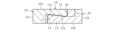
- the connecting portion in the present invention is such that the outer peripheral side of the circumferential end of one annular body extends in the axial direction to form an outer convex portion, and the inner peripheral surface thereof can be brought into contact with the rolling element.
- the inner diameter side is recessed to form an inner diameter side recess, and the inner circumferential surface of the other annular body pocket is extended in the axial direction to form the inner diameter side convex portion.
- the outer diameter side convex portion and the inner diameter side convex portion are engaged in the axial direction, and the engagement surface of the outer diameter side convex portion and the inner diameter side convex portion is used as the base end of the outer diameter side convex portion and the inner diameter side convex portion.
- a structure that is inclined with respect to the axial direction so that the tip side is thicker than the side is desirable.
- High rotation speed is achieved by a synergistic effect of the frictional force generated along the engagement surface between the outer diameter side convex portion and the inner diameter side convex portion and the axial component of the reaction force generated in the normal direction of the engagement surface. Even when a larger centrifugal force is applied, it is possible to reliably prevent the two annular bodies from separating in the axial direction.
- the connecting portion in the present invention preferably has a structure in which the inclination angle of the engaging surface between the outer diameter side convex portion and the inner diameter side convex portion is 5 ° or more.
- the connecting part in the present invention preferably has a structure in which the inner diameter side convex part is thicker than the outer diameter side convex part.
- the inner diameter side convex portion made thicker than the outer diameter side convex portion is larger in mass than the outer diameter side convex portion.
- the engagement surface of the outer diameter side convex portion and the inner diameter side convex portion is inclined with respect to the axial direction so that the distal end side is thicker than the proximal end side of the outer diameter side convex portion and the inner diameter side convex portion. Therefore, the deformation of the inner diameter side convex portion acts to increase the coupling force on the engagement surface between the outer diameter side convex portion and the inner diameter side convex portion.
- the coupling portion in the present invention has a structure in which an outer diameter side convex portion and an inner diameter side concave portion are formed at one circumferential end portion of the pocket, and an inner diameter side convex portion and an outer diameter side concave portion are formed at the other circumferential end portion. Is desirable. With such a structure, it is possible to make one annular body and the other annular body by using a kind of annular body manufactured by one mold, and the product cost can be reduced.
- the annular body in the present invention is made of a synthetic resin in that the weight of the cage can be reduced.
- the synthetic resin constituting the cyclic body any one selected from a polyamide resin, a polyether ether ketone resin, a polyphenylene sulfide resin, a polyphthalamide resin, or a polyamideimide resin is preferable.
- a ball bearing can be configured by adding an outer ring and an inner ring that rotate relative to each other and a ball interposed between the outer ring and the inner ring to the cage having the above-described configuration.
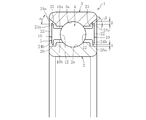
- the ball bearing according to the present invention is provided with an outer flange portion extending on the outer diameter side on the outer diameter portion on the opposite side of the annular body and an inner flange portion extending on the inner diameter side on the inner diameter portion on the opposite side, A structure where B ⁇ A is possible, where B is the clearance between the inner ring surface of the outer ring and A is the clearance between the inner flange part and the outer surface of the inner ring.
- an outer flange portion extending toward the outer diameter side is provided at the outer diameter portion on the counter mating side of the annular body, and an inner flange portion extending toward the inner diameter side is provided at the inner diameter portion on the counter mating side.
- the outer ring taper surface that expands the diameter from the inner side in the axial direction toward the outer side in the axial direction, and the outer diameter end of the outer flange portion is a tapered surface that increases in diameter from the inner side in the axial direction toward the outer side in the axial direction.
- B ⁇ A may be adopted, where B is a clearance between the flange tapered surface and the outer ring tapered surface, and A is a clearance between the inner flange portion and the outer diameter surface of the inner ring.
- the outer flange portion and the inner flange portion By providing the outer flange portion and the inner flange portion, it is possible to restrict the inflow of the lubricant into the bearing and prevent the lubricant from flowing out from the inside of the bearing. In particular, by setting B ⁇ A, it is possible to discharge the foreign matter that tends to stay inside while preventing the lubricant from flowing out to the outside. Further, by using the outer diameter end of the outer ring inner diameter surface of the outer ring in the bearing axial direction and the outer diameter end of the outer flange portion as tapered surfaces, it is possible to improve the action of discharging foreign matters to the outside.
- the ball bearing in the present invention is preferably applied to a transmission.
- the transmission is a main transmission that shifts the driving force from the engine and transmits it to the drive shaft, etc., and is roughly divided into a manual type and an automatic type, and a front axle drive (FWD) transaxle, rear There are wheel drive (RWD) transmissions and four-wheel drive (4WD) transfers (sub-transmissions).
- the rolling bearing is attached, for example, so as to be interposed between the main shaft and the main drive gear.
- the gap between the outer diameter surface of the ball and the inner peripheral surface of the pocket is enlarged, and the gap is reduced.
- Lubricating oil easily passes. Therefore, the shear resistance of the lubricating oil by the balls can be kept small. As a result, it becomes easy to reduce the torque generated between the cage and the balls due to the shear resistance of the lubricating oil by the balls. As a result, it is possible to easily provide a ball bearing for automobiles that is suitable for environmental problems such as fuel efficiency improvement in recent years.
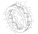
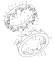
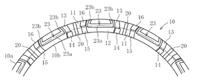
- FIG. 2 is an assembled perspective view showing a state after two annular bodies in FIG. 1 are joined together. It is a partial expanded view which shows the two annular bodies before a coupling
- FIG. 6 is an assembled perspective view showing a state after the two annular members of FIG. 5 are joined together. It is a partial expanded view which shows the two annular bodies before a coupling
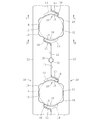
- FIG. 8 is a cross-sectional view taken along line AA in FIG. 3 and line EE in FIG. 7.
- FIG. 8 is a cross-sectional view taken along line BB in FIG. 3 and line FF in FIG. 7.
- FIG. 9 is a cross-sectional view taken along line CC in FIG. 4 and line GG in FIG. 8.
- FIG. 9 is a cross-sectional view taken along the line DD in FIG. 4 and the line HH in FIG. 8.
- the ball bearing of this embodiment is suitable for a sealed ball bearing for transmission as a high-speed bearing for automobiles used under oil bath lubrication in electric vehicles and hybrid vehicles, but is not a sealed type. It can also be applied to ball bearings for other purposes.
- the ball bearing 1 of this embodiment is arranged on the outer side of the inner ring 2 having the inner race surface 2 a formed on the outer diameter surface and on the outer side of the inner ring 2, and on the outer race surface 3 a on the inner diameter surface.
- the main part is composed of.
- the outer ring 3 is mounted on a fixed part such as a housing, and the inner ring 2 is mounted on a rotating part such as a rotating shaft.
- the seal portion 7 is composed of a seal member 8b made of an elastic member such as rubber that is integrally vulcanized and bonded to the core metal 8a.
- the seal member 8b is an inner diameter end portion of the outer ring 3 whose base end portion is a fixed side. And has a seal lip 8c in contact with the outer diameter end of the inner ring 2 at the tip.
- the present invention can also be applied to an outer ring rotation type in which the inner ring 2 is mounted on a fixed part such as a housing and the outer ring 3 is mounted on a rotating part such as a rotation shaft. .
- the ball bearing 1 includes a lightweight synthetic resin cage 5 for the purpose of suppressing deformation of the cage 5 due to centrifugal force under high speed rotation.
- this type of cage 5 has a hemispherical shape in which balls 4 (see FIG. 15) are rotatably accommodated on opposing surfaces 11 of two annular members 10 facing in the axial direction.
- the pockets 12 are formed at a plurality of locations in the circumferential direction, the opposing surfaces 11 of the annular body 10 are brought into contact with each other, and the two annular bodies 10 are coupled by the coupling portions 18 provided at both circumferential ends of the pocket 12. It has a symmetrical shape.
- the inner peripheral surface of the pocket 12 in the annular body 10 has a concave spherical shape with a single radius of curvature.
- FIGS. 1 to 4 show an embodiment of the present invention.
- FIGS. 1 and 3 show a state before two annular bodies 10 are joined together
- FIGS. 2 and 4 show two annular bodies 10 joined together.
- the state after having been made to show is shown.
- a groove for lubricating oil removal 19 having a circular cross section is provided on the inner peripheral surface of the pocket 12.
- the concave grooves 19 are formed to extend in the radial direction at two locations on the inner peripheral surface of the pocket 12 of each annular body 10. That is, the concave groove 19 reaches the outer diameter surface 10a from the inner diameter surface 10b of the annular body 10, and opens to the inner diameter surface 10b and the outer diameter surface 10a of the annular body 10 (see FIGS.
- a concave groove 20 is formed on the opposing surface 11 of the annular body 10 so as to reach the outer diameter surface 10a from the inner diameter surface 10b of the annular body 10 and open to the inner diameter surface 10b and the outer diameter surface 10a, respectively.
- FIGS. 5 to 8 show other embodiments of the present invention.
- FIGS. 5 and 7 show a state before two annular bodies 10 are joined
- FIGS. 6 and 8 show two annular bodies 10 joined. The state after having been made to show is shown.
- the case where a concave groove 21 for lubricating oil removal having a square cross section is provided on the inner peripheral surface of the pocket 12 is illustrated.
- the concave grooves 21 are formed at two locations on the inner peripheral surface of the pocket 12 of each annular body 10 so as to extend in the radial direction.
- the lubricating oil escape grooves 19 and 21 are provided on the inner peripheral surface of the pocket 12, so that a lubricating oil escape portion can be formed on the inside of the pocket. That is, the gap between the outer diameter surface of the ball 4 and the inner peripheral surface of the pocket 12 is enlarged, and the lubricating oil easily passes through the gap. Therefore, the shear resistance of the lubricating oil by the balls 4 can be kept small, and the torque can be easily reduced.
- the concave groove 20 is provided on the opposed surface 11 of the annular body 10, thereby reducing resistance when the lubricating oil passes. The amount of oil film can be reduced. In addition, excess lubricating oil and foreign matter can be discharged to the outside.
- the concave grooves 19 and 21 are formed on the inner peripheral surface of the pocket 12 so as to pass through between the radially outer diameter side and the radial inner diameter side. This makes it easier for the lubricating oil to pass through the gap between the inner circumferential surface and the inner circumferential surface.
- the concave grooves 19 and 21 are provided in two places of the internal peripheral surface of the pocket 12 of each annular body 10, the position and number of the concave grooves 19 and 21 are arbitrary.
- the stirring resistance of the lubricating oil can be reduced, and the torque can be further reduced.
- a U-shaped groove 23 may be provided on the inner peripheral surface of the pocket 12.
- the concave groove 23 in the cage of this embodiment includes a central main body groove 23a extending along the circumferential direction of the pocket, and a secondary groove 23b that is connected to the end of the central main body and opens to the outer diameter surface 10a of the annular body 10. It is what has.
- the concave groove 23 may have an elliptical shape, a V shape, a square shape, or the like in addition to the circular arc shape.
- the cage 5 of the above embodiment includes the following coupling structure as means for coupling the two annular bodies 10.
- each of the two annular bodies 10 has an outer diameter side by extending the outer diameter side of one circumferential end of the pocket 12 in the axial direction.
- the convex portion 13 is formed and the inner diameter side concave portion 14 is formed by denting the inner diameter side, and the inner diameter side convex portion 15 is formed by extending the inner diameter side of the other circumferential end of the pocket 12 in the axial direction.
- the outer diameter side recess 16 is formed by denting the outer diameter side.
- the two annular bodies 10 each form the outer diameter side convex portion 13 and the inner diameter side concave portion 14 at one circumferential end portion of the pocket 12, and the inner circumferential side convex portion at the other circumferential end portion.
- one annular body 10 and the other annular body 10 can be formed by using a kind of annular body 10 manufactured by one mold. The product cost can be reduced.
- the outer diameter side convex portion 13 of one annular body 10 is inserted into the outer diameter side concave portion 16 of the other annular body 10, and the inner diameter side convex portion 15 of one annular body 10 is inserted into the other annular body 10.
- the outer diameter side convex portion 13 and the inner diameter side convex portion 15 are engaged in the axial direction.
- the engagement surfaces 13a, 15a of the outer diameter side convex portion 13 and the inner diameter side convex portion 15 are thicker at the distal end side than the proximal end sides of the outer diameter side convex portion 13 and the inner diameter side convex portion 15. It is inclined with respect to the axial direction (see FIGS. 11 and 12).
- the opposing surfaces 11 of the two annular bodies 10 are brought into contact with each other, and the outer-diameter-side convex portion 13 and the inner-diameter-side convex portion 15 are set to a predetermined fastening allowance.
- a frictional force is generated along the engagement surfaces 13a and 15a of the outer diameter side convex portion 13 and the inner diameter side convex portion 15.
- the engagement surfaces 13a, 15a of the outer diameter side convex portion 13 and the inner diameter side convex portion 15 are thicker at the distal end side than the proximal end sides of the outer diameter side convex portion 13 and the inner diameter side convex portion 15.
- the joint part 18 which consists of the outer diameter side convex part 13, the inner diameter side concave part 14, the inner diameter side convex part 15, and the outer diameter side concave part 16 at both ends in the circumferential direction of the pocket 12 of the annular body 10.
- the inclination angle ⁇ (see FIGS. 11 and 12) of the engagement surfaces 13a and 15a between the outer diameter side convex portion 13 and the inner diameter side convex portion 15 needs to be 5 ° or more.
- the inclination angle ⁇ it becomes easy to suppress deformation of the engagement surfaces 13a and 15a when a large centrifugal force is applied due to high rotation, and a reaction force is applied to the engagement surfaces 13a and 15a.
- An axial component can be made to act reliably, and it becomes easy to ensure the coupling force of the two annular bodies 10.
- the inclination angle ⁇ of the engagement surfaces 13a and 15a is smaller than 5 °, it becomes difficult to suppress deformation of the engagement surfaces 13a and 15a when a large centrifugal force is applied due to high rotation. It becomes difficult to reliably apply the axial component of the reaction force to the surfaces 13a and 15a.
- the inner diameter side convex portion 15 is thicker than the outer diameter side convex portion 13 (t IN > t OUT ).
- the inner diameter side convex portion 15 thicker than the outer diameter side convex portion 13 in this way, the inner diameter side made thicker than the outer diameter side convex portion 13 when a large centrifugal force is applied due to high rotation. Since the mass of the convex portion 15 is larger than that of the outer diameter side convex portion 13, the inner diameter side convex portion 15 is deformed larger than the outer diameter side convex portion 13.
- the engagement surfaces 13a and 15a of the outer diameter side convex portion 13 and the inner diameter side convex portion 15 are thicker on the distal end side than the proximal end sides of the outer diameter side convex portion 13 and the inner diameter side convex portion 15. Therefore, the deformation of the inner diameter side convex portion 15 increases the coupling force between the outer diameter side convex portion 13 and the inner diameter side convex portion 15 at the engagement surfaces 13a, 15a.
- the two annular bodies 10 described above are made of synthetic resin in order to reduce the weight of the cage 5.
- This kind of commonly used resin with excellent wear resistance and seizure resistance such as polyethylene, polyamide, polyacetal, polyethylene terephthalate, polybutylene terephthalate, polycarbonate, polyphenylene sulfide, polyethersulfone, polyetherimide
- It can be formed of a synthetic resin such as polyamide imide, polyether ether ketone, thermoplastic polyimide, thermosetting polyimide, epoxy resin, or phenol resin.
- a glass fiber added to improve strength and dimensional stability can be used.
- a polyamide resin excellent in tensile elongation, tensile strength, impact resistance, wear resistance, lubricity, etc.
- a polyamide resin excellent in tensile elongation, tensile strength, impact resistance, wear resistance, lubricity, etc.
- PA46, PA66, PA9T, PA11, PA6, etc. polyetheretherketone resin
- PES polyphenylene sulfide resin
- PPA polyphthalamide resin
- PAI polyamideimide resin
- a polyamide resin having excellent tensile elongation, tensile strength, impact resistance, wear resistance, lubricity, and the like can be used, and a high-quality cage can be provided.
- the outer ring 3, the inner ring 2, and the balls 4 are made of metal such as bearing steel or carburized steel.
- the grease filled in this ball bearing is a semi-solid lubricating oil composed of a base oil, a thickener and an additive.
- the base oil constituting the grease include mineral oils such as paraffinic mineral oil and naphthenic mineral oil, hydrocarbon synthetic oils such as polybutene, poly- ⁇ -olefin, alkylbenzene, alkylnaphthalene, and alicyclic compounds, or Non-hydrocarbon synthetic oils such as natural fats and oils, polyol ester oils, phosphate esters, diester oils, polyglycol oils, silicone oils, polyphenyl ether oils, alkyl diphenyl ether oils, fluorinated oils, etc.
- base oils for grease Any oil can be used without particular limitation.
- the thickener examples include metal soap-based thickeners such as aluminum soap, lithium soap, sodium soap, composite lithium soap, composite calcium soap, composite aluminum soap, and urea compounds such as diurea compounds and polyurea compounds. These thickeners may be used alone or in combination of two or more.
- Known additives for lubricating grease include, for example, extreme pressure agents, amine-based and phenol-based antioxidants, metal deactivators such as benzotriazole, viscosity index improvers such as polymethacrylate and polystyrene, Examples thereof include solid lubricants such as molybdenum sulfide and graphite. These can be added alone or in combination of two or more.
- the sealed ball bearing 1 (see FIG. 15) provided with the cage 5 formed of the annular body 10 shown in FIGS. 1 to 14 has been described.
- the present invention can also be applied to a ball bearing 1 in which flanges 24a and 24b are provided on the outer diameter portion and the inner diameter portion of the annular body 10 on the opposite side.
- flanges 24a and 24b are provided on the outer diameter portion and the inner diameter portion of the annular body 10 on the opposite side.
- an annular body without a flange is illustrated, but the annular body 10 in FIGS. 1 to 14 is also provided with an outer diameter portion and an inner diameter portion on the opposite side. It is possible to have a structure provided with a collar portion.
- the outer flange portion 24 a provided on the outer diameter portion on the counter mating side of the annular body 10 extends to the bearing outer diameter side, and is provided on the inner diameter portion on the counter mating side of the annular body 10.
- the inner flange portion 24b extends toward the bearing inner diameter side.
- the end surface 22 on the counter mating side is formed into a flat shape (flat surface) parallel to the end surface in the bearing axial direction, and the inner diameter portion on the counter mating surface side of the inner flange portion 24b is aligned from the outer diameter side toward the inner diameter side.
- the taper surface is inclined to the surface side.
- a circumferential cutout 25 is provided at the axial end of the inner diameter surface of the outer ring 3, and a circumferential cutout is provided at the axial end of the outer diameter surface of the inner ring 2. 26 is provided.
- the circumferential notch 25 of the outer ring 3 has an outer ring taper surface whose diameter increases from the inner side in the axial direction toward the outer side in the axial direction. 25a.
- the taper angle ⁇ is, for example, about 20 ° to 45 °.
- the outer diameter end of the outer flange portion 24a is a flange taper surface 27 that expands from the inner side in the axial direction toward the outer side in the axial direction.
- the taper angle ⁇ of the taper surface 27 is set to be substantially the same as the taper angle ⁇ of the outer ring taper surface 25a.
- a predetermined clearance B is provided between the outer ring tapered surface 25 a and the tapered surface 27.
- a predetermined clearance A is also provided between the notch surface 26a of the circumferential notch 26 of the inner ring 2 and the inner flange 24b, and this clearance A is defined as the clearance B between the taper surface 25a and the taper surface 27.
- the following is set (B ⁇ A).
- the clearance B is a radial dimension from the outer diameter end of the outer flange portion 24a to the tapered surface 25a.
- A is about 0.5 mm to 1.2 mm
- B is preferably about 0.7 mm to 2.0 mm.
- outer flange portion 24a and the inner flange portion 24b it is possible to restrict the inflow of the lubricating oil into the bearing and prevent the lubricating oil from flowing out from the inside of the bearing.
- B ⁇ A it is possible to discharge the foreign matter that tends to stay inside the bearing while preventing the lubricant from flowing out of the bearing.
- the outer diameter end of the outer ring 3 in the bearing axial direction and the outer diameter end of the outer flange portion to the tapered surfaces 25a and 27, it is possible to improve the discharge action of foreign matter to the outside.
- the taper angles ⁇ and ⁇ are set to about 20 ° to 45 °, but the function is that “foreign matter that stays inside can be discharged to the outside while preventing the lubricant from flowing out”. Can be set within a range of 20 ° to 45 ° or even beyond this range.
- the notch surface of the circumferential notch 25 of the outer ring 3 may not be the tapered surface 25a. That is, as shown in FIG. 17, the circumferential notch 25 of the outer ring 3 is also rectangular in cross section. For this reason, the outer diameter end of the outer flange portion 24 a is an end surface parallel to the axial direction corresponding to the cutout surface 25 b of the circumferential cutout portion 25.
- the clearance between the outer flange portion 24a and the inner diameter surface of the outer ring 3 (in this case, the notch surface 25b of the circumferential notch 25) is B, and the outer diameter surface of the inner ring portion 24b and the inner ring 2 (in this case, When the clearance between the circumferential cutout 26 and the cutout surface 26a) is A, B ⁇ A. Also in this case, for example, when A is about 0.5 mm to 1.2 mm, B is preferably about 0.7 mm to 2.0 mm.
- FIGS. 16 and 17 Other configurations of the ball bearing 1 shown in FIGS. 16 and 17 are the same as those of the ball bearing 1 shown in FIG. 15, and therefore the same reference numerals are given to the same parts in FIG. 16 and FIG. Therefore, duplicate explanation is omitted.
- the present invention is not limited to the above-described embodiment, and various modifications can be made.
- the size and depth of the concave grooves 19 to 21 and 23 depend on the lubricating oil used. Various changes can be made as long as both the resistance when the lubricating oil passes and the reduction of the amount of oil film to be sheared can be achieved. For this reason, the number of the concave grooves 19 and 21 provided on the inner peripheral surface of the pocket 12 is not limited to two, and may be one or three or more.
- the groove 20 provided on the facing surface 11 of the annular body 10 is not limited to one, and may be two or more.
- the groove 20 may be provided on any facing surface 11 without being provided on all the facing surfaces 11.
- the flange portions 24a and 24b are Although it is preferable to provide, either one of the outer flange portion 24a and the inner flange portion 24b may be omitted, or both the flange portions 24a and 24b may be omitted. In the case where the flange portions 24a and 24b are provided, the thickness, radial length, etc. of the flange portions 24a and 24b are set in consideration of the balance, strength, weight, clearances A and B, etc. during rotation.
- the size, shape, and the like of the circumferential notches 25, 26 are set in consideration of the thickness, radial length, and the like of the flanges 24a, 24b. Note that the number of pockets 12 holding the balls 4 can be arbitrarily increased or decreased.
Landscapes
- Engineering & Computer Science (AREA)
- General Engineering & Computer Science (AREA)
- Mechanical Engineering (AREA)
- Rolling Contact Bearings (AREA)
Abstract
Description
Claims (17)
- 軸方向に向き合う二枚の環状体の対向面に玉を収容する半球状のポケットを周方向の複数箇所に形成し、前記対向面を衝合させて前記ポケットの周方向両端部に設けられた結合部により二枚の環状体を結合させた玉軸受用保持器であって、前記ポケットの内周面に潤滑油抜け用凹溝を設けたことを特徴とする玉軸受用保持器。
- 前記凹溝は、環状体の内径面から外径面に達するように形成されている請求項1に記載の玉軸受用保持器。
- 前記凹溝は、その断面形状が円弧状をなす請求項1又は2に記載の玉軸受用保持器。
- 前記凹溝は、その断面形状が角状をなす請求項1又は2に記載の玉軸受用保持器。
- 前記凹溝は、ポケット周方向に沿って延びる中央本体溝とこの中央本体の端部に連設されて環状体の外径面に開口する副溝とを有するコの字状をなす請求項1に記載の玉軸受用保持器。
- 前記環状体の対向面に、環状体の内径面から外径面に達する凹溝を設けた請求項1~5のいずれか一項に記載の玉軸受用保持器。
- 前記環状体の反合わせ側の端面をフラット形状とした請求項1~6のいずれか一項に記載の玉軸受用保持器。
- 前記結合部は、一方の環状体のポケットの周方向端部外径側を軸方向に延出させて外径側凸部を形成してその内周面を前記玉と当接可能にすると共に内径側を凹ませて内径側凹部を形成し、かつ、他方の環状体のポケットの周方向端部内径側を軸方向に延出させて内径側凸部を形成してその内周面を前記玉と当接可能にすると共に外径側を凹ませて外径側凹部を形成し、前記外径側凸部を外径側凹部に挿入すると共に前記内径側凸部を内径側凹部に挿入することにより前記外径側凸部と内径側凸部を軸方向で係合させ、前記外径側凸部と内径側凸部との係合面を、外径側凸部および内径側凸部の基端側よりも先端側が厚肉となるように軸方向に対して傾斜させた請求項1~7のいずれか一項に記載の玉軸受用保持器。
- 前記結合部は、前記外径側凸部と前記内径側凸部との係合面の傾斜角度を5°以上とした請求項8に記載の玉軸受用保持器。
- 前記結合部は、前記内径側凸部を前記外径側凸部よりも厚肉にした請求項8又は9に記載の玉軸受用保持器。
- 前記結合部は、前記ポケットの一方の周方向端部に外径側凸部および内径側凹部を形成すると共に、他方の周方向端部に内径側凸部および外径側凹部を形成した請求項8~10のいずれか一項に記載の玉軸受用保持器。
- 前記環状体は合成樹脂製である請求項1~11のいずれか一項に記載の玉軸受用保持器。
- 前記合成樹脂は、ポリアミド樹脂、ポリエーテルエーテルケトン樹脂、ポリフェニレンサルファイド樹脂、ポリフタルアミド樹脂あるいはポリアミドイミド樹脂から選択されたいずれか一つである請求項12に記載の玉軸受用保持器。
- 請求項1~13のいずれか一項に記載の保持器と、互いに相対回転する外輪および内輪と、前記外輪と内輪との間に介在する玉とを備えた玉軸受。
- 環状体の反合わせ側の外径部に外径側に延びる外鍔部と反合わせ側の内径部に内径側に延びる内鍔部とを設けると共に、外鍔部と外輪の内径面との間のクリアランスをBとし、内鍔部と内輪の外径面との間のクリアランスをAとしたときに、B≧Aとした請求項14に記載の玉軸受。
- 環状体の反合わせ側の外径部に外径側に延びる外鍔部と反合わせ側の内径部に内径側に延びる内鍔部とを設け、外輪の内径面の軸受軸方向外端部を、軸方向内側から軸方向外側に向かって拡径する外輪テーパ面とすると共に、前記外鍔部の外径端を、軸方向内側から軸方向外側に向かって拡径する鍔テーパ面とし、鍔テーパ面と外輪テーパ面との間のクリアランスをBとし、内鍔部と内輪の外径面との間のクリアランスをAとしたときに、B≧Aとした請求項14に記載の玉軸受。
- トランスミッションに適用される請求項14~16のいずれか一項に記載の玉軸受。
Priority Applications (3)
| Application Number | Priority Date | Filing Date | Title |
|---|---|---|---|
| CN201280011840.7A CN103429915B (zh) | 2011-03-09 | 2012-02-20 | 球轴承用保持器及球轴承 |
| DE112012001115T DE112012001115T5 (de) | 2011-03-09 | 2012-02-20 | Kugellagerkäfig und Kugellager |
| US14/000,912 US8961023B2 (en) | 2011-03-09 | 2012-02-20 | Ball bearing retainer and ball bearing |
Applications Claiming Priority (4)
| Application Number | Priority Date | Filing Date | Title |
|---|---|---|---|
| JP2011051744A JP5653798B2 (ja) | 2011-03-09 | 2011-03-09 | 玉軸受用保持器および玉軸受 |
| JP2011-051744 | 2011-03-09 | ||
| JP2011126350A JP5836649B2 (ja) | 2011-06-06 | 2011-06-06 | 玉軸受用保持器および玉軸受 |
| JP2011-126350 | 2011-06-06 |
Publications (1)
| Publication Number | Publication Date |
|---|---|
| WO2012120996A1 true WO2012120996A1 (ja) | 2012-09-13 |
Family
ID=46797965
Family Applications (1)
| Application Number | Title | Priority Date | Filing Date |
|---|---|---|---|
| PCT/JP2012/053968 Ceased WO2012120996A1 (ja) | 2011-03-09 | 2012-02-20 | 玉軸受用保持器および玉軸受 |
Country Status (4)
| Country | Link |
|---|---|
| US (1) | US8961023B2 (ja) |
| CN (1) | CN103429915B (ja) |
| DE (1) | DE112012001115T5 (ja) |
| WO (1) | WO2012120996A1 (ja) |
Cited By (1)
| Publication number | Priority date | Publication date | Assignee | Title |
|---|---|---|---|---|
| US20140187374A1 (en) * | 2012-12-27 | 2014-07-03 | Jtekt Corporation | Liquid-lubricated bearing and vehicle pinion shaft support device |
Families Citing this family (12)
| Publication number | Priority date | Publication date | Assignee | Title |
|---|---|---|---|---|
| JP5528964B2 (ja) * | 2010-09-22 | 2014-06-25 | Ntn株式会社 | 転がり軸受 |
| US9518606B2 (en) * | 2015-03-09 | 2016-12-13 | Seagate Technology Llc | Bearing apparatus with surface migration channels |
| DE102015220363B4 (de) * | 2015-10-20 | 2020-08-13 | Aktiebolaget Skf | Zweiteiliger Lagerkäfig |
| DE102015224859A1 (de) * | 2015-12-10 | 2017-06-14 | Schaeffler Technologies AG & Co. KG | Kugellagerkäfig |
| JP6874455B2 (ja) * | 2017-03-22 | 2021-05-19 | 株式会社ジェイテクト | 転がり軸受 |
| JP2020024013A (ja) * | 2018-08-08 | 2020-02-13 | Ntn株式会社 | 転がり軸受の樹脂被膜付き保持器 |
| DE102019104628B4 (de) * | 2019-02-25 | 2023-01-26 | Hiwin Technologies Corp. | Kugelkäfig für ein Kugellager |
| US10641331B1 (en) | 2019-02-26 | 2020-05-05 | Hiwin Technologies Corp. | Ball cage for ball bearing |
| US11131344B1 (en) * | 2020-04-24 | 2021-09-28 | Schaeffler Technologies AG & Co. KG | Snap-fit ball bearing cage |
| IT202000024403A1 (it) * | 2020-10-16 | 2022-04-16 | Skf Ab | Unita’ cuscinetto provvista di dispositivo di ritenzione ad alte prestazioni |
| FR3131944B1 (fr) * | 2022-01-19 | 2024-01-05 | Ntn Snr Roulements | Cage de roulement à billes à alvéoles conformées pour une fabrication additive, et son procédé de fabrication |
| US12305707B2 (en) * | 2023-04-19 | 2025-05-20 | Aktiebolaget Skf | Rolling-element bearing cage, rolling-element bearing, vehicle, and method for assembling a rolling-element bearing cage |
Citations (4)
| Publication number | Priority date | Publication date | Assignee | Title |
|---|---|---|---|---|
| JP2007040383A (ja) * | 2005-08-02 | 2007-02-15 | Nsk Ltd | 玉軸受用保持器及び玉軸受 |
| JP2008121817A (ja) * | 2006-11-14 | 2008-05-29 | Jtekt Corp | 転がり軸受用保持器 |
| JP2008286387A (ja) * | 2007-04-18 | 2008-11-27 | Ntn Corp | 自動車補機用軸受 |
| JP2011021671A (ja) * | 2009-07-15 | 2011-02-03 | Ntn Corp | 玉軸受用保持器および玉軸受 |
Family Cites Families (13)
| Publication number | Priority date | Publication date | Assignee | Title |
|---|---|---|---|---|
| CH485959A (it) * | 1968-04-23 | 1970-02-15 | Riv Officine Di Villar Perosa | Gabbia per cuscinetti a sfere |
| US4451098A (en) | 1982-08-26 | 1984-05-29 | Usm Corporation | Ball separator assembly |
| GB2156912B (en) * | 1984-04-04 | 1987-09-03 | Skf Svenska Kullagerfab Ab | Cage for bearings |
| US4902145A (en) | 1989-06-12 | 1990-02-20 | Emerson Electric Co. | Ball separator for bearing assembly |
| JPH04236820A (ja) | 1991-01-14 | 1992-08-25 | Ntn Corp | 転がり軸受用保持器 |
| JP2002130294A (ja) | 2000-10-19 | 2002-05-09 | Nsk Ltd | 玉軸受用保持器 |
| JP2004263819A (ja) * | 2003-03-04 | 2004-09-24 | Nsk Ltd | 多点接触型玉軸受 |
| JP2006342901A (ja) | 2005-06-09 | 2006-12-21 | Nsk Ltd | 転がり軸受 |
| US7507028B2 (en) * | 2005-06-27 | 2009-03-24 | Spx Corporation | Bearing retainer assembly and method |
| JP2009019766A (ja) | 2007-06-11 | 2009-01-29 | Nsk Ltd | 転がり軸受用保持器及び転がり軸受 |
| JP2009115128A (ja) | 2007-11-02 | 2009-05-28 | Nsk Ltd | 転がり軸受用保持器及び転がり軸受 |
| WO2010150707A1 (ja) * | 2009-06-26 | 2010-12-29 | Ntn株式会社 | 深みぞ玉軸受用の合成樹脂製保持器および深みぞ玉軸受並びにギヤ支持装置 |
| US8408808B2 (en) * | 2009-12-07 | 2013-04-02 | Baldor Electric Company | Two-piece bearing cage with side face grease carrying cavities |
-
2012
- 2012-02-20 DE DE112012001115T patent/DE112012001115T5/de not_active Withdrawn
- 2012-02-20 US US14/000,912 patent/US8961023B2/en not_active Expired - Fee Related
- 2012-02-20 CN CN201280011840.7A patent/CN103429915B/zh not_active Expired - Fee Related
- 2012-02-20 WO PCT/JP2012/053968 patent/WO2012120996A1/ja not_active Ceased
Patent Citations (4)
| Publication number | Priority date | Publication date | Assignee | Title |
|---|---|---|---|---|
| JP2007040383A (ja) * | 2005-08-02 | 2007-02-15 | Nsk Ltd | 玉軸受用保持器及び玉軸受 |
| JP2008121817A (ja) * | 2006-11-14 | 2008-05-29 | Jtekt Corp | 転がり軸受用保持器 |
| JP2008286387A (ja) * | 2007-04-18 | 2008-11-27 | Ntn Corp | 自動車補機用軸受 |
| JP2011021671A (ja) * | 2009-07-15 | 2011-02-03 | Ntn Corp | 玉軸受用保持器および玉軸受 |
Cited By (2)
| Publication number | Priority date | Publication date | Assignee | Title |
|---|---|---|---|---|
| US20140187374A1 (en) * | 2012-12-27 | 2014-07-03 | Jtekt Corporation | Liquid-lubricated bearing and vehicle pinion shaft support device |
| US9316256B2 (en) * | 2012-12-27 | 2016-04-19 | Jtekt Corporation | Liquid-lubricated bearing and vehicle pinion shaft support device |
Also Published As
| Publication number | Publication date |
|---|---|
| CN103429915A (zh) | 2013-12-04 |
| DE112012001115T5 (de) | 2013-12-24 |
| US8961023B2 (en) | 2015-02-24 |
| CN103429915B (zh) | 2017-02-08 |
| US20130330031A1 (en) | 2013-12-12 |
Similar Documents
| Publication | Publication Date | Title |
|---|---|---|
| CN103429915B (zh) | 球轴承用保持器及球轴承 | |
| CN103518071B (zh) | 球轴承用保持器及球轴承 | |
| JP5615649B2 (ja) | 玉軸受 | |
| CN103109100B (zh) | 滚动轴承 | |
| JP5863284B2 (ja) | 玉軸受用保持器および玉軸受 | |
| WO2019065603A1 (ja) | 玉軸受用保持器及び玉軸受 | |
| JP5623312B2 (ja) | 玉軸受用保持器および玉軸受 | |
| JP2013142407A (ja) | 玉軸受用保持器および玉軸受 | |
| JP6096260B2 (ja) | 玉軸受用保持器および玉軸受 | |
| JP2012107674A (ja) | 玉軸受 | |
| JP5653798B2 (ja) | 玉軸受用保持器および玉軸受 | |
| JP5591609B2 (ja) | 玉軸受用保持器および玉軸受 | |
| JP5836649B2 (ja) | 玉軸受用保持器および玉軸受 | |
| WO2023149266A1 (ja) | 玉軸受 | |
| JP2012102845A (ja) | 玉軸受用保持器および玉軸受 | |
| JP5781365B2 (ja) | 玉軸受用保持器および玉軸受 | |
| JP2013117238A (ja) | 玉軸受用保持器および玉軸受 | |
| JP2013200006A (ja) | 玉軸受およびその保持器 | |
| JP2012172834A (ja) | 密封型転がり軸受 | |
| WO2023189431A1 (ja) | 玉軸受 | |
| WO2024241906A1 (ja) | 玉軸受 | |
| JP2013200007A (ja) | 玉軸受 | |
| WO2023248750A1 (ja) | 玉軸受 | |
| JP5855411B2 (ja) | 玉軸受用保持器および玉軸受 |
Legal Events
| Date | Code | Title | Description |
|---|---|---|---|
| 121 | Ep: the epo has been informed by wipo that ep was designated in this application |
Ref document number: 12754243 Country of ref document: EP Kind code of ref document: A1 |
|
| WWE | Wipo information: entry into national phase |
Ref document number: 14000912 Country of ref document: US |
|
| WWE | Wipo information: entry into national phase |
Ref document number: 1120120011155 Country of ref document: DE Ref document number: 112012001115 Country of ref document: DE |
|
| 122 | Ep: pct application non-entry in european phase |
Ref document number: 12754243 Country of ref document: EP Kind code of ref document: A1 |