WO2012120692A1 - ホットスタンプ用鋼板及びその製造方法と高強度部品の製造方法 - Google Patents
ホットスタンプ用鋼板及びその製造方法と高強度部品の製造方法 Download PDFInfo
- Publication number
- WO2012120692A1 WO2012120692A1 PCT/JP2011/056124 JP2011056124W WO2012120692A1 WO 2012120692 A1 WO2012120692 A1 WO 2012120692A1 JP 2011056124 W JP2011056124 W JP 2011056124W WO 2012120692 A1 WO2012120692 A1 WO 2012120692A1
- Authority
- WO
- WIPO (PCT)
- Prior art keywords
- steel sheet
- hot
- composite oxide
- hot stamping
- steel
- Prior art date
- Legal status (The legal status is an assumption and is not a legal conclusion. Google has not performed a legal analysis and makes no representation as to the accuracy of the status listed.)
- Ceased
Links
Images


Classifications
-
- C—CHEMISTRY; METALLURGY
- C22—METALLURGY; FERROUS OR NON-FERROUS ALLOYS; TREATMENT OF ALLOYS OR NON-FERROUS METALS
- C22C—ALLOYS
- C22C38/00—Ferrous alloys, e.g. steel alloys
- C22C38/02—Ferrous alloys, e.g. steel alloys containing silicon
-
- B—PERFORMING OPERATIONS; TRANSPORTING
- B21—MECHANICAL METAL-WORKING WITHOUT ESSENTIALLY REMOVING MATERIAL; PUNCHING METAL
- B21B—ROLLING OF METAL
- B21B1/00—Metal-rolling methods or mills for making semi-finished products of solid or profiled cross-section; Sequence of operations in milling trains; Layout of rolling-mill plant, e.g. grouping of stands; Succession of passes or of sectional pass alternations
- B21B1/22—Metal-rolling methods or mills for making semi-finished products of solid or profiled cross-section; Sequence of operations in milling trains; Layout of rolling-mill plant, e.g. grouping of stands; Succession of passes or of sectional pass alternations for rolling plates, strips, bands or sheets of indefinite length
-
- B—PERFORMING OPERATIONS; TRANSPORTING
- B21—MECHANICAL METAL-WORKING WITHOUT ESSENTIALLY REMOVING MATERIAL; PUNCHING METAL
- B21D—WORKING OR PROCESSING OF SHEET METAL OR METAL TUBES, RODS OR PROFILES WITHOUT ESSENTIALLY REMOVING MATERIAL; PUNCHING METAL
- B21D22/00—Shaping without cutting, by stamping, spinning, or deep-drawing
- B21D22/02—Stamping using rigid devices or tools
- B21D22/022—Stamping using rigid devices or tools by heating the blank or stamping associated with heat treatment
-
- B—PERFORMING OPERATIONS; TRANSPORTING
- B32—LAYERED PRODUCTS
- B32B—LAYERED PRODUCTS, i.e. PRODUCTS BUILT-UP OF STRATA OF FLAT OR NON-FLAT, e.g. CELLULAR OR HONEYCOMB, FORM
- B32B15/00—Layered products comprising a layer of metal
- B32B15/01—Layered products comprising a layer of metal all layers being exclusively metallic
- B32B15/013—Layered products comprising a layer of metal all layers being exclusively metallic one layer being formed of an iron alloy or steel, another layer being formed of a metal other than iron or aluminium
-
- C—CHEMISTRY; METALLURGY
- C21—METALLURGY OF IRON
- C21D—MODIFYING THE PHYSICAL STRUCTURE OF FERROUS METALS; GENERAL DEVICES FOR HEAT TREATMENT OF FERROUS OR NON-FERROUS METALS OR ALLOYS; MAKING METAL MALLEABLE, e.g. BY DECARBURISATION OR TEMPERING
- C21D8/00—Modifying the physical properties of ferrous metals or ferrous alloys by deformation combined with, or followed by, heat treatment
-
- C—CHEMISTRY; METALLURGY
- C21—METALLURGY OF IRON
- C21D—MODIFYING THE PHYSICAL STRUCTURE OF FERROUS METALS; GENERAL DEVICES FOR HEAT TREATMENT OF FERROUS OR NON-FERROUS METALS OR ALLOYS; MAKING METAL MALLEABLE, e.g. BY DECARBURISATION OR TEMPERING
- C21D8/00—Modifying the physical properties of ferrous metals or ferrous alloys by deformation combined with, or followed by, heat treatment
- C21D8/02—Modifying the physical properties of ferrous metals or ferrous alloys by deformation combined with, or followed by, heat treatment during manufacturing of plates or strips
- C21D8/0221—Modifying the physical properties of ferrous metals or ferrous alloys by deformation combined with, or followed by, heat treatment during manufacturing of plates or strips characterised by the working steps
- C21D8/0236—Cold rolling
-
- C—CHEMISTRY; METALLURGY
- C22—METALLURGY; FERROUS OR NON-FERROUS ALLOYS; TREATMENT OF ALLOYS OR NON-FERROUS METALS
- C22C—ALLOYS
- C22C38/00—Ferrous alloys, e.g. steel alloys
- C22C38/001—Ferrous alloys, e.g. steel alloys containing N
-
- C—CHEMISTRY; METALLURGY
- C22—METALLURGY; FERROUS OR NON-FERROUS ALLOYS; TREATMENT OF ALLOYS OR NON-FERROUS METALS
- C22C—ALLOYS
- C22C38/00—Ferrous alloys, e.g. steel alloys
- C22C38/002—Ferrous alloys, e.g. steel alloys containing In, Mg, or other elements not provided for in one single group C22C38/001 - C22C38/60
-
- C—CHEMISTRY; METALLURGY
- C22—METALLURGY; FERROUS OR NON-FERROUS ALLOYS; TREATMENT OF ALLOYS OR NON-FERROUS METALS
- C22C—ALLOYS
- C22C38/00—Ferrous alloys, e.g. steel alloys
- C22C38/04—Ferrous alloys, e.g. steel alloys containing manganese
-
- C—CHEMISTRY; METALLURGY
- C22—METALLURGY; FERROUS OR NON-FERROUS ALLOYS; TREATMENT OF ALLOYS OR NON-FERROUS METALS
- C22C—ALLOYS
- C22C38/00—Ferrous alloys, e.g. steel alloys
- C22C38/06—Ferrous alloys, e.g. steel alloys containing aluminium
-
- C—CHEMISTRY; METALLURGY
- C22—METALLURGY; FERROUS OR NON-FERROUS ALLOYS; TREATMENT OF ALLOYS OR NON-FERROUS METALS
- C22C—ALLOYS
- C22C38/00—Ferrous alloys, e.g. steel alloys
- C22C38/12—Ferrous alloys, e.g. steel alloys containing tungsten, tantalum, molybdenum, vanadium, or niobium
-
- C—CHEMISTRY; METALLURGY
- C22—METALLURGY; FERROUS OR NON-FERROUS ALLOYS; TREATMENT OF ALLOYS OR NON-FERROUS METALS
- C22C—ALLOYS
- C22C38/00—Ferrous alloys, e.g. steel alloys
- C22C38/14—Ferrous alloys, e.g. steel alloys containing titanium or zirconium
-
- C—CHEMISTRY; METALLURGY
- C22—METALLURGY; FERROUS OR NON-FERROUS ALLOYS; TREATMENT OF ALLOYS OR NON-FERROUS METALS
- C22C—ALLOYS
- C22C38/00—Ferrous alloys, e.g. steel alloys
- C22C38/16—Ferrous alloys, e.g. steel alloys containing copper
-
- C—CHEMISTRY; METALLURGY
- C22—METALLURGY; FERROUS OR NON-FERROUS ALLOYS; TREATMENT OF ALLOYS OR NON-FERROUS METALS
- C22C—ALLOYS
- C22C38/00—Ferrous alloys, e.g. steel alloys
- C22C38/18—Ferrous alloys, e.g. steel alloys containing chromium
-
- C—CHEMISTRY; METALLURGY
- C22—METALLURGY; FERROUS OR NON-FERROUS ALLOYS; TREATMENT OF ALLOYS OR NON-FERROUS METALS
- C22C—ALLOYS
- C22C38/00—Ferrous alloys, e.g. steel alloys
- C22C38/18—Ferrous alloys, e.g. steel alloys containing chromium
- C22C38/22—Ferrous alloys, e.g. steel alloys containing chromium with molybdenum or tungsten
-
- C—CHEMISTRY; METALLURGY
- C22—METALLURGY; FERROUS OR NON-FERROUS ALLOYS; TREATMENT OF ALLOYS OR NON-FERROUS METALS
- C22C—ALLOYS
- C22C38/00—Ferrous alloys, e.g. steel alloys
- C22C38/18—Ferrous alloys, e.g. steel alloys containing chromium
- C22C38/24—Ferrous alloys, e.g. steel alloys containing chromium with vanadium
-
- C—CHEMISTRY; METALLURGY
- C22—METALLURGY; FERROUS OR NON-FERROUS ALLOYS; TREATMENT OF ALLOYS OR NON-FERROUS METALS
- C22C—ALLOYS
- C22C38/00—Ferrous alloys, e.g. steel alloys
- C22C38/18—Ferrous alloys, e.g. steel alloys containing chromium
- C22C38/28—Ferrous alloys, e.g. steel alloys containing chromium with titanium or zirconium
-
- C—CHEMISTRY; METALLURGY
- C22—METALLURGY; FERROUS OR NON-FERROUS ALLOYS; TREATMENT OF ALLOYS OR NON-FERROUS METALS
- C22C—ALLOYS
- C22C38/00—Ferrous alloys, e.g. steel alloys
- C22C38/18—Ferrous alloys, e.g. steel alloys containing chromium
- C22C38/30—Ferrous alloys, e.g. steel alloys containing chromium with cobalt
-
- C—CHEMISTRY; METALLURGY
- C22—METALLURGY; FERROUS OR NON-FERROUS ALLOYS; TREATMENT OF ALLOYS OR NON-FERROUS METALS
- C22C—ALLOYS
- C22C38/00—Ferrous alloys, e.g. steel alloys
- C22C38/18—Ferrous alloys, e.g. steel alloys containing chromium
- C22C38/32—Ferrous alloys, e.g. steel alloys containing chromium with boron
-
- C—CHEMISTRY; METALLURGY
- C22—METALLURGY; FERROUS OR NON-FERROUS ALLOYS; TREATMENT OF ALLOYS OR NON-FERROUS METALS
- C22C—ALLOYS
- C22C38/00—Ferrous alloys, e.g. steel alloys
- C22C38/18—Ferrous alloys, e.g. steel alloys containing chromium
- C22C38/38—Ferrous alloys, e.g. steel alloys containing chromium with more than 1.5% by weight of manganese
-
- C—CHEMISTRY; METALLURGY
- C21—METALLURGY OF IRON
- C21D—MODIFYING THE PHYSICAL STRUCTURE OF FERROUS METALS; GENERAL DEVICES FOR HEAT TREATMENT OF FERROUS OR NON-FERROUS METALS OR ALLOYS; MAKING METAL MALLEABLE, e.g. BY DECARBURISATION OR TEMPERING
- C21D6/00—Heat treatment of ferrous alloys
- C21D6/005—Heat treatment of ferrous alloys containing Mn
-
- C—CHEMISTRY; METALLURGY
- C21—METALLURGY OF IRON
- C21D—MODIFYING THE PHYSICAL STRUCTURE OF FERROUS METALS; GENERAL DEVICES FOR HEAT TREATMENT OF FERROUS OR NON-FERROUS METALS OR ALLOYS; MAKING METAL MALLEABLE, e.g. BY DECARBURISATION OR TEMPERING
- C21D8/00—Modifying the physical properties of ferrous metals or ferrous alloys by deformation combined with, or followed by, heat treatment
- C21D8/02—Modifying the physical properties of ferrous metals or ferrous alloys by deformation combined with, or followed by, heat treatment during manufacturing of plates or strips
- C21D8/0221—Modifying the physical properties of ferrous metals or ferrous alloys by deformation combined with, or followed by, heat treatment during manufacturing of plates or strips characterised by the working steps
- C21D8/0226—Hot rolling
-
- C—CHEMISTRY; METALLURGY
- C21—METALLURGY OF IRON
- C21D—MODIFYING THE PHYSICAL STRUCTURE OF FERROUS METALS; GENERAL DEVICES FOR HEAT TREATMENT OF FERROUS OR NON-FERROUS METALS OR ALLOYS; MAKING METAL MALLEABLE, e.g. BY DECARBURISATION OR TEMPERING
- C21D8/00—Modifying the physical properties of ferrous metals or ferrous alloys by deformation combined with, or followed by, heat treatment
- C21D8/02—Modifying the physical properties of ferrous metals or ferrous alloys by deformation combined with, or followed by, heat treatment during manufacturing of plates or strips
- C21D8/0247—Modifying the physical properties of ferrous metals or ferrous alloys by deformation combined with, or followed by, heat treatment during manufacturing of plates or strips characterised by the heat treatment
- C21D8/0273—Final recrystallisation annealing
Definitions
- the present invention relates to a steel sheet for hot stamping excellent in delayed fracture resistance, a method for producing the same, and a high-strength part to be hot stamped using this steel sheet.
- the present invention relates to a method for manufacturing a high-strength part used for an automotive structural part.
- the hot stamping method has recently been used as a practical technique as a method of simultaneously satisfying the high strength, workability and product accuracy of steel sheets.
- Patent Document 1 This is to heat a steel plate to an austenite region of about 900 ° C. and then press-form it hot, and quench it by bringing it into contact with a normal temperature mold during press-molding to obtain a high-strength material.
- This hot stamping method also reduces the residual stress introduced during press forming, so that problems such as cracking and defective shape freezing that are problematic in high-strength steel sheets exceeding 1180 MPa in TS are suppressed. It is possible to manufacture parts with good product accuracy.
- High-strength steel sheets used for automobiles and the like have the problem of formability described above as the strength is increased.
- a high-strength material exceeding 1000 MPa has an essential problem of hydrogen embrittlement (sometimes called placement or delayed fracture) as is conventionally known.
- hydrogen embrittlement sometimes called placement or delayed fracture
- Patent Document 2 proposes a method in which the hydrogen concentration in the hot stamping heating atmosphere is 6% by volume or less and the dew point is 10 ° C. This relates to a method for controlling the heating atmosphere of hot stamping. That is, by controlling the hydrogen concentration and dew point, the penetration of external hydrogen into the steel sheet during heating is suppressed. Therefore, it does not improve the steel plate itself, but can be applied only to a hot stamp having an atmosphere control device.
- Patent Document 3 proposes a steel sheet for hot stamping with improved delayed fracture resistance.
- This technique is a composite oxidation of one or more of Mg oxide, sulfide, composite crystallized product, and composite precipitate with an average particle size in the range of 0.01 to 5.0 ⁇ m in steel. 1 ⁇ 10 2 to 1 ⁇ 10 7 per square mm, and these oxides and composite crystallized and composite precipitates using these oxides as nuclei act as hydrogen trap sites. It has improved destructibility.
- Patent Document 4 discloses that bainite or martensite is the largest phase in area ratio, and oxides, sulfides, nitrides, and composite crystals of Nb, V, Cr, Ti, and Mo in the grains. Any one or more of particles and composite precipitates, average particle diameter d: 0.001 to 5.0 ⁇ m, density ⁇ : 100 to 1 ⁇ 10 13 particles / mm 2 , standard particle diameter standard deviation ⁇ and average particle
- a technique for forming a high-strength thin steel sheet excellent in hydrogen embrittlement resistance characterized by satisfying the ratio d of diameter d ⁇ / d ⁇ 1.0 and having a tensile strength of 980 MPa or more is disclosed.
- Patent Document 5 proposes that a Fe—Nb—Mn composite oxide is formed in a steel plate and the hydrogen trapping capability is enhanced by increasing the uneven distribution of Nb and Mn in the oxide.
- the technique described in Patent Document 5 is a technique premised on a steel plate for enamel with a low C (carbon) content (usually 0.01% by mass or less), and a high C content such as a steel plate for automobiles.
- a strong steel plate (C is 0.05% by mass or more) cannot be ignored because the deoxidation action of C cannot be ignored.
- the amount of hydrogen to be a problem in a steel plate for enamel is as high as 10 to 100 ppm, whereas the amount of hydrogen in a very low concentration of 1 to 3 ppm is a problem in a high strength steel plate. Therefore, the technique described in Patent Document 5 cannot be applied as it is to a high-strength steel sheet having a high C content.
- the present technology was explained about the delayed fracture countermeasure by the hydrogen embrittlement of the hot stamped steel sheet.
- the problem is that there is currently no technology for suppressing delayed fracture due to hydrogen embrittlement when hot stamping a high strength steel sheet with a high C content.
- an object of the present invention is to form an effective hydrogen trap in a steel material while ensuring strength in a high-strength steel sheet having a high C content, and is excellent in hot stamping component strength and delayed fracture resistance.
- the inventors of the present invention have paid attention to the fact that it is effective to trap hydrogen that penetrates into the steel sheet.
- Fe—Mn-based composite oxide can be generated in the steel sheet, and hydrogen can be trapped at the interface between the composite oxide and the steel that is the matrix.
- metal oxides In high-strength steel sheets with a high C content, metal oxides usually become defects as inclusions. For this reason, the oxygen in steel is removed as much as possible, and the production
- the present inventors have found that by reducing the Al concentration in the steel sheet, weakening the deoxidation effect, and ensuring the oxygen concentration in the steel, a composite oxide can be generated even in a steel sheet with a high C content. It was.
- the inventors have also intensively studied a manufacturing method therefor. It was found that the molten steel having a high C content has a high viscosity, so that it is difficult for the Fe—Mn composite oxide to float and the Fe—Mn composite oxide is easily generated in the steel.
- a steel sheet for hot stamping characterized by containing Fe—Mn-based composite oxide particles having an average diameter of 0.1 to 15 ⁇ m, which is made of a chemical component of the balance Fe and inevitable impurities. S, P, and N are inevitable impurities, but are restricted to the following contents.
- (5) For hot stamping, wherein the steel plate according to any one of (1) and (2) is plated with aluminum, zinc-aluminum, or zinc plating steel sheet.
- the rolling rate of rough rolling is set to 70% or more
- the rolling rate of finish rolling is set to 70% or more.
- a method for manufacturing a steel sheet for hot stamping characterized by hot rolling.
- a method for producing a steel sheet for hot stamping characterized in that the hot-rolled steel sheet hot-rolled according to (6) is further pickled and cold-rolled at a rolling rate of 30% or more.
- a method for producing a hot stamping steel sheet comprising subjecting the cold-rolled cold-rolled steel sheet according to (7) to annealing. (9) After heating the steel sheet according to either (1) or (2) above to an austenite region temperature of Ac 3 or higher, molding in the mold is started, and cooling in the mold after molding.
- a method for producing a high-strength part characterized by performing quenching.
- the high-strength steel sheet for hot stamping of the present invention forms composite oxide particles effective as hydrogen trap sites and surrounding voids by stretching and crushing the composite oxide. From this, it is not necessary to strictly control the size (average particle diameter) and existence state (density) of oxides and the like as in the prior art, and a steel sheet having excellent delayed fracture characteristics can be provided. If a member made of a steel plate is used, it is considered that it can greatly contribute to the weight reduction and safety improvement of the automobile, and the industrial contribution is great.
- FIG. 1 is a schematic view showing a state in which a coarse composite oxide is stretched and crushed so that many crushed voids (hydrogen trapping ability) are formed in the steel sheet.
- FIG. 2 is a schematic diagram showing a state in which coarse oxides are stretched and crushed to form less crushed voids (hydrogen trapping ability) in the steel sheet.
- FIG. 3 is a schematic diagram showing that crushing voids are not formed when fine oxide is present.
- FIG. 4 is a cross-sectional view of the mold shape used in the examples.
- FIG. 5 is a diagram showing the shape of the punch used in the example as viewed from above.
- FIG. 6 is a diagram showing the shape of the dice used in the example as viewed from below.
- FIG. 7 is a schematic view of a hot stamped molded product.
- FIG. 8 is a diagram showing a shape of a test part for evaluating delayed fracture resistance when viewed from above.
- the present inventors cast a slab in which a Fe—Mn complex oxide is produced in steel in a steel making process, and the slab is hot-rolled and cold-rolled to stretch and crush the complex oxide.
- fine voids can be formed between the finely crushed Fe-Mn composite oxide particles, and these voids are effective as hydrogen trap sites. It was trapped and found to be less susceptible to delayed fracture. Furthermore, these voids have been found to have a size and shape that are unlikely to start cracks, and an attempt was made to apply them to hot stamp materials that require strength.
- C 0.05-0.40%
- C is an element added to secure the material by using the cooled structure as martensite.
- C of 0.05% or more is necessary for improving the strength.
- the C content is preferably 0.15% or more, and more preferably 0.2% or more.
- the C content is preferably 0.35% or less, and more preferably 0.3% or less.
- Si acts as a deoxidizing element.
- Si for reducing the oxygen content is specified to be 0.02% or less.
- the Si content is preferably 0.015% or less, more preferably 0.01% or less.
- the lower limit of the Si content is not particularly limited, but 0.001% is set as the lower limit because it takes time and cost to remove Si.
- Mn is an element that affects hot stamping and hardenability, and is effective in increasing the strength of the steel sheet. Further, Mn is an important component in the present invention because it forms an Fe—Mn composite oxide by addition. This composite oxide becomes a hydrogen trap site that causes delayed fracture. For this reason, the addition of Mn is effective for improving delayed fracture resistance.
- the formed complex oxide is fine, it is effective to suppress the generation of coarse cracks on the punched surface.
- Mn metal-organic compound
- the Mn content is preferably 3% or less. More desirably, the Mn content is 2.0% or less, and more preferably 1.50% or less.
- S (S: 0.02% or less) S is contained as an unavoidable impurity, and when it is contained excessively, the workability is deteriorated and the toughness is deteriorated, and the delayed fracture resistance is lowered. For this reason, the smaller the S, the better.
- the allowable range is specified to be 0.02% or less. Preferably, it is 0.01% or less. Furthermore, by limiting the S content to 0.005% or less, the impact characteristics are dramatically improved.
- P 0.03% or less
- P is contained as an unavoidable impurity and is an element that adversely affects toughness when added excessively, and deteriorates delayed fracture resistance. For this reason, the smaller the P, the better.
- Al is an element necessary for being used as a deoxidizer for molten steel.
- the amount of Al having a deoxidizing effect exceeds 0.005%, the amount of oxide for improving delayed fracture resistance cannot be secured.
- the upper limit was made 0.005%.
- the Al content is preferably 0.004% or less, and more preferably 0.003% or less.
- the lower limit is not particularly limited, but since it takes time and cost to remove Al, it is realistic to set it to 0.0002% or more.
- Ti 0.0005 to 0.01% or less
- Ti is also a deacidifying element, and the lower limit is not particularly limited. However, it takes time and cost for the Ti removal treatment, so 0.0005% or more, preferably 0.001% or more is sufficient. On the other hand, the addition of a large amount reduces the oxide that improves the delayed fracture resistance, so the upper limit was made 0.01%. Further, it is preferably 0.008% or less, and if it is further 0.006% or less, the effect of improving the delayed fracture resistance is great.
- N 0.01% or less
- the acceptable range of N is defined as 0.01% or less. Preferably it is 0.008% or less. If it is 0.006% or less, since toughness deterioration can be suppressed more, it is preferable.
- Both Cr and Mo are elements that improve the hardenability, and have the effect of precipitating M 23 C 6 type carbide in the matrix, and have the effect of increasing the strength and miniaturizing the carbide. Therefore, one or two of Cr and Mo are added in a total amount of 0.005 to 2%. If it is less than 0.005%, these effects cannot be expected sufficiently. More preferably, it is 0.01% or more. Furthermore, the effect will become remarkable if it is 0.05% or more. On the other hand, if it exceeds 2% in total, the yield strength is excessively increased, and the toughness is deteriorated to deteriorate the delayed fracture resistance. If possible, it is more preferably 1.5% or less from the viewpoint of delayed fracture resistance.
- O is an element necessary for forming the Fe—Mn composite oxide, and it is necessary to contain 0.003% to 0.03%. If it is less than 0.003%, a sufficient amount of Fe—Mn composite oxide cannot be formed. From the viewpoint of forming the Fe—Mn composite oxide, the content is preferably 0.005% or more. On the other hand, if the content exceeds 0.03%, internal defects such as blowholes are generated in the slab, so the upper limit was defined as 0.03%. From the viewpoint of internal defects, a smaller amount is better, and the O content is preferably 0.02% or less. If possible, defects are significantly reduced at 0.015% or less.
- B is an element effective for improving the hardenability. In order to make such an effect effective, it is necessary to add 0.0005% or more. In order to acquire the effect reliably, it is preferable to set it as 0.001% or more. Furthermore, 0.0015% or more is more preferable. On the other hand, even if added excessively, the effect is saturated, so 0.01% was made the upper limit. From the viewpoint of cost effectiveness, the content is preferably 0.008% or less, and more preferably 0.005% or less.
- Nb, V, W and Co are carbide generating elements, and precipitates are generated to ensure the strength of hot stamped and quenched members. Furthermore, these are elements contained in the Fe—Mn composite oxide, function as hydrogen trap sites effective in improving delayed fracture resistance, and are necessary for improving delayed fracture resistance. One or more of these elements may be added. When the amount added exceeds 1% in total, the increase in yield strength becomes excessively large. Therefore, it is more preferable to set it as 0.7% or less. If possible, it is more preferably 0.5% or less. On the other hand, if it is less than 0.005%, the strength improvement and the effect as a hydrogen trap site are hardly exhibited. From the viewpoint of reliably obtaining the effect, the content is preferably 0.01% or more.
- Ni and Cu are both elements that improve the strength and toughness, but if added in excess of 2% in total, the castability decreases, so the upper limit is made 2%.
- the content is preferably reduced from the viewpoint of castability, and more preferably 1% or less. 0.5% is more preferable.
- the total content is less than 0.005%, the effect of improving the strength and toughness is hardly exhibited. Therefore, one or more of Ni and Cu may be added in a total amount of 0.005% or more. From the viewpoint of strength and toughness, it is preferably 0.01% or more. Furthermore, it is more preferable that it is 0.02% or more.
- steel adjusted to the component composition of the present invention in normal melting, continuous casting, and steel plate manufacturing processes can be melted.
- the effects of the present invention can be obtained more remarkably by adding Mn, Si, Al, etc. in this order.
- the mechanism by which these steelmaking conditions affect the characteristics of the invention steel is considered as follows.
- the composition fluctuation of the composite oxide of the steel of the present invention is mainly due to the thermodynamic oxide composition fluctuation during molten steel to solidification. Basically, in the process in which the oxide composition approaches an equilibrium state due to changes in system concentration and temperature, it is expressed using a non-equilibrium state.
- oxygen in the molten steel forms a coarse oxide of A.
- element B having a strong binding force with oxygen Element A in the oxide is replaced by element B.
- a coarse A and B composite oxide (AB composite oxide) is formed.
- Such a mechanism requires an elapsed time for forming a coarse composite oxide after the weak deoxidation element is added.
- the composition of the AB composite oxide becomes too close to the oxide of B as an equilibrium state, and the effect of the composite oxide becomes small. Again, oxides float and come out of the molten steel, hindering the effect of improving characteristics.
- the voids functioning as hydrogen trap sites are mainly formed in the cold rolling process after hot rolling. That is, the Fe—Mn composite oxide is crushed by rolling, and crushed voids are formed around the composite oxide particles. Therefore, it is important to control the shape of the complex oxide in the hot rolling process.
- the composite oxide particles dispersed in the steel were originally an integral composite oxide. That is, it is considered that at the time of casting the molten steel whose component adjustment was completed, what was a large oxide was stretched, crushed and finely dispersed in the rolling process. Such stretching and crushing mainly occurs in the rolling process.
- the steel plate temperature is high (1000 ° C. or higher), the oxide is mainly stretched.
- the oxide is mainly crushed. If the composition is unevenly distributed in the oxide in such a process, the degree of stretching differs depending on the portion of the oxide, and the shape of the oxide becomes complicated. Further, it is expected that the thinned (thinned) portion is preferentially crushed, and the portion having a large shape variation is preferentially crushed due to the concentration of deformation stress. As a result, parts having different compositions are efficiently crushed and dispersed. During this crushing, voids may be formed around the composite oxide particles, which are also considered as hydrogen trap sites in the steel, which will significantly improve the delayed fracture resistance of hot stamp products. .
- FIG. 1 is a schematic diagram showing a state in which a coarse composite oxide is stretched and crushed to form many crushed voids (hydrogen trapping ability) in the steel sheet.
- the coarse composite oxide 1 is formed by combining two different kinds of oxides 1-1 and 1-2.
- This composite oxide 1 becomes a composite oxide 3 stretched by hot rolling rough rolling 2 (indicated by an arrow in FIG. 1), and the respective oxides 3-1 and 3-2 are also stretched.
- hot rolling finish rolling 4 indicated by an arrow in FIG. 1).
- many crushed voids 5 are formed around the crushed composite oxide particles 5-1, 5-2. This crushing void 5 also becomes a hydrogen trap site, and the delayed fracture resistance is improved.
- FIG. 2 shows a case where a coarse oxide is simply contained as in the prior art.
- the coarse oxide 6 becomes an oxide 7 stretched by hot rolling rough rolling 2 (indicated by an arrow in FIG. 2).
- hot rolling finish rolling 4 indicated by an arrow in FIG. 1.
- the crushed oxide 8 does not disperse fine composite oxide particles as in the present invention, and therefore, a sufficient crushed void 5 as a hydrogen trap site cannot be obtained.
- FIG. 3 is a schematic diagram showing that crushing voids are not formed before hot rolling, that is, when fine oxide is present in the slab stage. If the composite oxide 6 'is fine at the slab stage as shown in FIG. 3, the fine oxide 6' is difficult to be stretched by rough rolling 2 (indicated by an arrow in FIG. 3). As a result, even the finish rolling 4 (indicated by an arrow in FIG. 3) is not crushed so much, so that the crushed void 5 as a hydrogen trap site is hardly generated.
- cold rolling has the effect of further finely crushing the oxide, similarly to hot rolling finish rolling 4 (indicated by arrows in FIGS. 1 to 3).
- the composite oxide particles are uniformly dispersed in the steel plate.
- the interface between the composite oxide particles and the steel serving as the matrix serves as a hydrogen trap site, it is preferable that the specific surface area (surface area per unit weight) of the composite oxide particles is large. For this reason, it is desirable that the composite oxide is fine. Moreover, it is desirable that the composite oxide is fine from the viewpoint of defect suppression.
- the gap generated around the composite oxide particles also becomes smaller when the composite oxide particles are small. Therefore, it is desirable to refine the composite oxide also from the viewpoint of reducing the void volume in the steel sheet.
- the ability to stretch, pulverize, and refine the composite oxide by rolling is convenient because the current process can be maintained.
- the Fe—Mn composite oxide targeted in the present invention is an Fe—Mn composite oxide in which oxides such as Fe, Mn, Si, and Al are combined and integrated.
- the composite oxide is desirably fine, but if it is too fine, the hydrogen trap effect is reduced. Therefore, the diameter of the complex oxide is preferably 0.10 ⁇ m or more. This is because an oxide smaller than this range has a very small effect as a hydrogen trap site, which is a major characteristic of the steel sheet of the present invention.
- it is 0.50 ⁇ m or more, more preferably 1.0 ⁇ m or more, and further preferably 2.0 ⁇ m or more.
- the upper limit of the diameter need not be particularly limited in view of the effect of the present invention.
- the average diameter of the composite oxide is 15 ⁇ m or less, preferably 10 ⁇ m or less, more preferably 5 ⁇ m or less.
- the size is not particularly limited.
- the voids have a major axis of 0.1 to 5 ⁇ m and an aspect ratio of 2 to 10.
- the average diameter of the crushing voids is 100% or less of the average diameter of the composite oxide (particles). From the point of view of defects, it is better that the gap is small, and preferably 80% or less.
- the average diameter of the voids in the present invention is defined as the average value obtained by measuring the major and minor diameters of five voids.
- the composite oxide is softened due to the high temperature, and the hardness difference from iron as the parent phase is small. That is, in the temperature range of about 1000 ° C. or higher, which is the temperature range of rough rolling, the complex oxide is hardly crushed by rolling, and the complex oxide is stretched.
- the composite oxide becomes difficult to stretch.
- cracks to the extent that fine cracks are generated occur in part of the complex oxide.
- cold rolling the composite oxide is crushed starting from the generated microcracks.
- the temperature range for hot working is too high, it is not possible to impart a strain sufficient to form cracks to the composite oxide.
- the shape of the composite oxide is not elongated but close to a spherical shape, so that cracks are difficult to occur. It is necessary for the formation of cracks to be moderately stretched and thin.
- hot rolling it is necessary to control and impart the extension of the complex oxide by moderate deformation in a higher temperature range and the formation of cracks in the lower temperature range.
- the form of the complex oxide that forms such cracks becomes more complex and efficient when the concentration difference exists in the complex oxide and the deformability is different as described above. A void can be formed.
- the hot rolling heating temperature is preferably 1000 to 1400 ° C. Desirably, it is 1050 degreeC or more.
- hot rolling rough rolling can be performed at 1000 degreeC or more
- hot rolling finish rolling can be performed at 1000 degrees C or less after that.
- the final finish rolling temperature is preferably 800 ° C. or lower. Desirably, it is 750 degreeC or less. This is because the stretched composite oxide is crushed. It is economically advantageous that the winding temperature is 700 ° C. or lower.
- the rolling rate is 70% or more by rough rolling and the rolling rate is 70% or more by finish rolling.
- the rolling reduction in finish rolling is more preferably 80% or more. More preferably, it is 90% or more. That is, this rolling rate allows the composite oxide to be stretched and crushed, and becomes a hydrogen trap site effective for improving delayed fracture resistance.
- the rolling rate in cold rolling is preferably 30% or more. This is because the composite oxide is stretched and crushed at a cold rolling rate of 30% or more to become a hydrogen trap site effective in improving delayed fracture resistance, and further improved in delayed fracture resistance. Furthermore, if it is 40% or more, it is more preferable, and if it is 50% or more, a delay fracture-proof characteristic improvement becomes remarkable. In particular, when deep drawability is required, the rolling rate in cold rolling is preferably 60% or more.
- annealing When annealing, either a continuous annealing method or a box annealing method applied to a normal cold-rolled steel sheet may be used.
- hot stamping steel plates are used as automotive structural parts, most of them are used after surface treatment, and in particular, they are often used as plated steel plates.
- the plated steel sheet aluminum plating, zinc-aluminum plating, and galvanization are usually performed.
- the steel sheet for hot stamping of the present invention can also be plated as usual.
- the surface of the steel sheet may be plated at a rate of 30 to 100 g / m 2 on one side.
- the steel sheet is first heated to the austenite region, that is, the austenite region above the Ac 3 transformation point. In this case, it is sufficient to reach the austenite region, and if it is too high, coarsening and oxidation become remarkable, which is not preferable.
- a high-strength part can be manufactured by starting molding with a mold, rapidly cooling while being restrained with a mold after processing, and performing martensitic transformation and quenching.
- the rapid cooling rate from the austenite region is set to a critical cooling rate that is affected by the steel composition / structure.
- the cooling completion temperature is preferably below the martensite transformation completion temperature.
- tempering is not particularly required, but may be performed as necessary for correction when the strength is too high, or to improve toughness.
- Example 1 Steels having chemical components shown in Tables 1-1 to 1-3 and Tables 2-1 to 2-3 were cast to produce slabs.
- Tables 2-1 to 2-3 are based on steel types A, X, and AC described in Table 1-1 and Table 1-2, and are described in Tables 2-1 to 2-3.
- blended each component element which shows is shown.
- some cold-rolled steel sheets are hot dip galvanized (weight per unit: 30 to 90 g / m 2 on one side), alloyed hot dip galvanized (weight per unit: 30 to 90 g / m 2 on one side), hot dip galvanized (weight per unit: single side) 30 to 100 g / m 2 ) was applied in a continuous hot dipping line.
- the steel sheet types are shown in Tables 1-1 to 3 and 2-1 to 3. The legend of steel sheet type is shown below.
- HR hot rolled steel sheet
- CR cold rolled steel sheet (annealed material)
- AL hot dip galvanized steel sheet
- GI hot dip galvanized steel sheet
- GA galvannealed steel sheet.
- Fracture voids around the complex oxide ⁇ : average diameter of voids 0.1 ⁇ m or more, X: Means an average diameter of voids of less than 0.1 ⁇ m.
- the average diameter of the crushing voids around the composite oxide is preferably 0.1 ⁇ m or more.
- these cold-rolled steel sheets were heated to an austenite region of 880 to 950 ° C., which is at least Ac3 point, by furnace heating, and then hot-formed.
- the cross section of the mold shape is shown in FIG.
- the legend in FIG. 4 shows the die shape of the die 9 and the punch 10.
- the shape of the punch viewed from above is shown in FIG.
- the legend in FIG. 5 shows the punch 10.
- the shape of the die viewed from below is shown in FIG.
- the legend in FIG. 6 shows the die 9.
- the mold was determined to be a die shape with a clearance of 1.6 mm following the punch shape.
- the blank size was 1.6 mm thick ⁇ 300 mm ⁇ 500 mm.
- the molding conditions were a punch speed of 10 mm / s, a pressing force of 200 tons, and a holding time at the bottom dead center of 5 seconds.
- a schematic diagram of the hot stamped molded article 11 is shown in FIG.
- the quenching characteristics of the hot stamped parts were evaluated based on the martensite area ratio by observing the microstructure that had undergone nital corrosion after polishing the cross section with an optical microscope.
- the evaluation results are shown in Tables 1-1 to 1-3 and Tables 2-1 to 2-3.
- the legend is as follows. ⁇ : Martensite area ratio 90% or more, ⁇ : Martensite area ratio 80% or more, X: Martensite area ratio is less than 80%.
- the martensite area ratio was set to a preferable range of 80% or more.
- the delayed fracture resistance was evaluated by applying stress by piercing.
- Piercing was performed using a punch having a diameter of 10 mm at a center piercing hole position 13 of the test part 12 shown in FIG. 8 and using a die having a diameter of 10.5 mm.
- FIG. 8 shows the shape of the component viewed from above.
- the legend in FIG. 8 shows the part 12 and the pierce hole center 13.
- Piercing was performed within 30 minutes after hot forming, and the number thereof was set to ten.
- the evaluation standard for hydrogen embrittlement resistance was to observe the entire circumference of the hole one week after piercing and to determine the presence or absence of cracks. Observation was performed with a magnifying glass or an electron microscope. The determination results are shown in Table 3.
- the legend is as follows. Total number of microcracks in 10 points: A: 0, ⁇ : 1 piece ⁇ : Less than 5 X: 5 or more. Although the number of micro cracks is less than 5 as acceptable, it is needless to
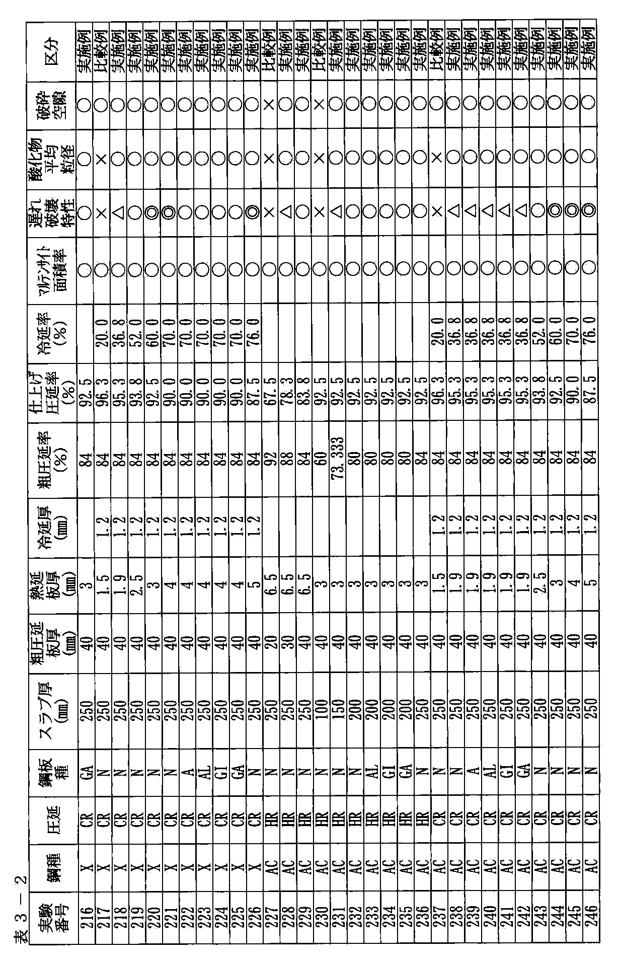
- Example 2 The rolling conditions were examined using steel types A, X, and AC shown in Tables 1-1 and 1-2. These slabs were heated to 1050 to 1350 ° C. and hot rolled to form hot rolled steel sheets at a finishing temperature of 800 to 900 ° C. and a winding temperature of 450 to 680 ° C. Tables 3-1 and 3-2 show the thickness, rough rolling rate, and finish rolling rate of the slab, rough rolled plate, and hot rolled plate. Thereafter, some hot-rolled steel sheets were pickled and then cold-rolled. Tables 3-1 and 3-2 show the thickness of the cold rolled sheet and the cold rolling rate.
- HR hot rolled steel sheet
- CR cold rolled steel sheet
- A annealed material
- N no annealing
- AL hot dip galvanized steel sheet
- GI hot dip galvanized steel sheet
- GA galvannealed steel sheet.
- these cold-rolled steel sheets were heated to an austenite region of 880 to 950 ° C., which is at least Ac3 point, by furnace heating, and then hot-formed.
- FIG. 4 shows a cross section of the mold shape used in the examples.
- the legend in FIG. 4 shows the die shape of the die 9 and the punch 10.
- the shape of the punch viewed from above is shown in FIG.
- the legend in FIG. 5 shows the punch 10.
- the shape of the die viewed from below is shown in FIG.
- the legend in FIG. 6 shows the die 9.
- the mold was determined to be a die shape with a clearance of 1.6 mm following the punch shape.
- the blank size was 1.6 mm thick ⁇ 300 mm ⁇ 500 mm.
- the molding conditions were a punch speed of 10 mm / s, a pressing force of 200 tons, and a holding time at the bottom dead center of 5 seconds.
- a schematic diagram of the hot press-formed product is shown in FIG.
- the quenching characteristics of the steel sheet were evaluated based on the martensite area ratio by observing the microstructure subjected to nital corrosion after polishing the cross section with an optical microscope.
- the evaluation results are shown in Tables 3-1 and 3-2.
- the legend is shown below. ⁇ : Martensite area ratio 90% or more, ⁇ : Martensite area ratio 80% or more, X: Martensite area ratio is less than 80%.
- the delayed fracture resistance was evaluated by applying stress by piercing.
- Piercing was performed using a punch having a diameter of 10 mm at the center piercing hole position 13 of the test part 12 shown in FIG. 8 and using a diameter die having a clearance of 15% ⁇ 2.
- FIG. 8 shows the shape of the component viewed from above.
- the legend in FIG. 8 shows the part 12 and the pierce hole center 13.
- Piercing was performed within 30 minutes after hot forming, and the number thereof was set to ten.
- the evaluation standard for hydrogen embrittlement resistance was to observe the entire circumference of the hole one week after piercing and to determine the presence or absence of cracks. Observation was performed with a magnifying glass or an electron microscope. The determination results are shown in Tables 3-1 and 3-2. The legend is shown below. Total number of microcracks in 10 points: A: 0, ⁇ : 1 piece ⁇ : Less than 5 X: 5 or more.
- the present invention can be used as a steel material for hot stamping, and can be used in a wide range of industrial fields such as automotive parts, home appliances and machine industries.
Landscapes
- Chemical & Material Sciences (AREA)
- Engineering & Computer Science (AREA)
- Mechanical Engineering (AREA)
- Materials Engineering (AREA)
- Metallurgy (AREA)
- Organic Chemistry (AREA)
- Physics & Mathematics (AREA)
- Thermal Sciences (AREA)
- Crystallography & Structural Chemistry (AREA)
- Heat Treatment Of Sheet Steel (AREA)
- Treatment Of Steel In Its Molten State (AREA)
Abstract
Description
従って、特許文献5に記載の技術を、C含有量の多い高強度鋼板へは、そのまま適用できない。
さらに、複合酸化物の周囲に間隙があると、水素トラップ効果がより向上することもわかった。
C含有量が多い溶融鋼は粘度が高いので、Fe−Mn系複合酸化物が浮上し難く、鋼中にFe−Mn系複合酸化物を生成させやすいことがわかった。
C:0.05~0.40%、
Si:0.001~0.02%、
Mn:0.1~3%、
Al:0.0002~0.005%、
Ti:0.0005~0.01%、
O:0.003~0.03%、および
CrとMoのうち1種又は2種の合計で0.005~2%、
を含有し、残部Fe及び不可避的不純物の化学成分からなり、かつ平均直径0.1~15μmのFe−Mn系複合酸化物粒子を分散して含有することを特徴とするホットスタンプ用鋼板。
なお、S、P、Nは不可避的不純物であるが、以下の含有量に規制する。
S:0.02%以下、
P:0.03%以下、
N:0.01%以下、
(2) さらに、質量%で、
(a)B:0.0005~0.01%、
(b)Nb、V、W、Coの1種または2種以上を合計で0.005~1%、
(c)Ni、Cuの1種または2種を合計で0.005~2%、
で示される(a)~(c)の3群のうち1群または2群以上に含まれる成分を含有することを特徴とする上記(1)に記載のホットスタンプ用鋼板。
(3) 前記複合酸化物粒子の周囲に空隙を有することを特徴とする(1)または(2)のいずれか1項に記載のホットスタンプ用鋼板。
(4) 前記複合酸化物粒子の周囲の空隙の平均径が、前記複合酸化物粒子の平均径の10~100%であることを特徴とする(1)または(2)のいずれか1項に記載のホットスタンプ用鋼板。
(5) 上記(1)または(2)のいずれか1項に記載の鋼板にアルミめっき、亜鉛−アルミめっき、または亜鉛めっきの内のいずれかのめっきを施したことを特徴とするホットスタンプ用鋼板。
(6) 上記(1)または(2)のいずれかに記載の化学成分の鋳片を熱間圧延する際に、粗圧延の圧延率を70%以上、仕上げ圧延の圧延率を70%以上として熱間圧延することを特徴とするホットスタンプ用鋼板の製造方法。
(7) 上記(6)に記載の熱間圧延した熱延鋼板を、さらに酸洗して圧延率30%以上で冷間圧延を施すことを特徴とするホットスタンプ用鋼板の製造方法。
(8) 上記(7)に記載の冷間圧延した冷延鋼板に焼鈍を施すことを特徴とするホットスタンプ用鋼板の製造方法。
(9) 上記(1)または(2)のいずれかに記載の鋼板をAc3以上のオーステナイト域の温度に加熱した後、金型での成形を開始し、成形後に金型中にて冷却して焼入れを行うことを特徴とする高強度部品の製造方法。
図2は、粗大酸化物が延伸、破砕されて鋼板に破砕空隙(水素トラップ能)が少なく形成される状態を示す模式図である。
図3は、微細酸化物が存在する場合には、破砕空隙が形成されないことを示す模式図である。
図4は、実施例で用いた金型形状の断面図である。
図5は、実施例で用いたパンチを上方から見た形状を示す図である。
図6は、実施例で用いたダイスを下方から見た形状を示す図である。
図7は、ホットスタンプ成形品の模式図である。
図8は、耐遅れ破壊特性の評価のための試験部品を上方から見た形状を示す図である。
Cは、冷却後の組織をマルテンサイトとして材質を確保するために添加する元素である。強度向上のために0.05%以上のCが必要であるが、C含有量が0.40%を超えると、衝撃変形時の強度や溶接性が劣化するため、Cは0.05~0.40%とした。強度の観点から、さらに、C含有量を0.15%以上とすることが好ましく、さらに0.2%以上とするとより好ましい。
Siは、脱酸元素として作用する。本発明は酸化物量を一定以上確保することが必須となるため、酸素含有量を低減するSiは0.02%以下に規定した。有効な酸化物量を得るためにはSi含有量を0.015%以下、さらには0.01%以下とすることが好ましい。Si含有量の下限は特に問わないが、脱Si処理に時間と費用がかかることから、0.001%を下限とする。
Mnは、ホットスタンプ、焼き入れ性に影響する元素であり、鋼板の強度上昇に有効である。また、Mnは添加によりFe−Mn複合酸化物を形成させるため、本発明においては重要な成分である。この複合酸化物が遅れ破壊の要因となる水素のトラップサイトとなる。このため、Mnの添加は耐遅れ破壊性の向上に効果的である。
Sは、不可避的不純物として含有され、過多に含有する場合には加工性を劣化させるとともに、靱性劣化の原因となり、耐遅れ破壊特性を低下させる。このため、Sは少ないほどよい。許容できる範囲として、0.02%以下に規定した。好ましくは、0.01%以下にするとよい。さらに、S含有量を0.005%以下に規制することにより、衝撃特性が飛躍的に向上する。
Pは、不可避的不純物として含有され、過多に添加された場合には靱性に悪影響を及ぼす元素であり、耐遅れ破壊特性を低下させる。このため、Pは少ないほどよい。許容できる範囲として、0.03%以下に規制した。さらに、0.025%以下とすることが好ましく、さらに0.02%以下とすると耐遅れ破壊特性の改善効果は大きい。
Alは、溶鋼の脱酸材として使われるために必要な元素である。本発明は酸化物量を一定以上確保することが必要なため、脱酸効果のあるAlが0.005%を超えると耐遅れ破壊特性を向上させる酸化物量が確保できない。このため、上限を0.005%とした。マージンを考慮するとAl含有量を0.004%以下とすることが好ましく、さらに0.003%以下とするとなお好ましい。また、下限は特に限定するものではないが、脱Al処理に時間と費用がかかることから、0.0002%以上とするのが現実的である。
Tiも脱酸性の元素であり下限は特に限定するものではないが、脱Ti処理に時間と費用がかかることから、0.0005%以上、好ましくは0.001%以上とすれば十分である。一方、多量の添加は耐遅れ破壊特性を向上させる酸化物を減少させるため上限を0.01%とした。さらに、0.008%以下とすることが好ましく、さらに0.006%以下とすると耐遅れ破壊特性の改善効果は大きい。
Nは、0.01%を超えると窒化物の粗大化および固溶Nによる時効硬化により、靱性が劣化する傾向がみられる。このため、Nは少ないほどよい。Nの許容できる範囲として0.01%以下の範囲に規定した。好ましくは0.008%以下とするとよい。0.006%以下であれば、より靭性劣化を抑制できるので好ましい。
Cr、Moは、共に焼入れ性を向上させる元素であり、またマトリックス中へM23C6型炭化物を析出させる効果を有し、強度を高めるとともに、炭化物を微細化する作用を有する。このためCr、Moの1種または2種を合計で0.005~2%添加する。0.005%未満ではこれらの効果が十分期待できない。より好ましくは0.01%以上であるとよい。さらには、0.05%以上であればその効果は顕著になる。また、合計で2%を超えると降伏強度が過度に上昇し、また靱性を劣化させて耐遅れ破壊特性を低下させる。できれば、耐遅れ破壊特性の観点から1.5%以下とすることが、より好ましい。
Oは、本発明においてはFe−Mn複合酸化物を形成させるために必要な元素であり、0.003~0.03%含有させることが必要である。0.003%未満であると、十分な量のFe−Mn複合酸化物を形成することができない。Fe−Mn複合酸化物の形成の観点からは、0.005%以上とすることが好ましい。一方0.03%を超えて含有させると鋳片にブローホールなどの内部欠陥が発生するため、上限を0.03%に規定した。内部欠陥の観点からは、少ない方がよく、O含有量は0.02%以下であることが好ましい。できれば、0.015%以下であると欠陥は顕著に減少する。
Bは、焼き入れ性を向上させるのに有効な元素である。このような効果を有効にするためには、0.0005%以上の添加が必要ある。その効果を確実に得るためには、0.001%以上とすることが好ましい。さらには、0.0015%以上であればより好ましい。一方、過多に添加してもその効果は飽和するので、0.01%を上限とした。コスト対効果の観点でみると、0.008%以下にすることが好ましく、できれば0.005%以下とするとさらに好ましい。
Nb、V、W、Coは炭化物生成元素であり、析出物を生成させてホットスタンプ、焼き入れした部材の強度を確保する。さらに、これらはFe−Mn系複合酸化物に含有され、耐遅れ破壊特性向上に有効な水素トラップサイトとして働き、耐遅れ破壊性を改善するために必要な元素である。これらの元素のうち1種または2種以上を添加すればよい。添加量が、合計で1%を超えて添加すると、降伏強度の上昇が過度に大きくなる。そのため、0.7%以下とすることがより好ましい。できれば、0.5%以下とすることがさらに好ましい。一方、0.005%未満では強度向上、および水素トラップサイトとしての効果が発揮されにくい。その効果を確実に得る観点から、0.01%以上とすることが好ましい。
Ni、Cuは、共に強度および靱性を向上させる元素であるが、合計で2%を超えて添加すると、鋳造性が低下するため上限を2%とする。鋳造性の観点から含有量を少なくするとよく、1%以下であることがより好ましい。0.5%であれば、さらに好ましい。一方、合計で0.005%未満では強度および靱性の向上効果が発揮されにくいため、Ni、Cuの1種または2種以上を合計で0.005%以上添加するとよい。強度、靭性の観点から0.01%以上であることが好ましい。さらには、0.02%以上あると、より好ましい。
本発明での空隙の平均径とは、空隙5個の長径、短径をそれぞれ測定し、それらの平均値と定義する。
表1−1~1−3、表2−1~2−3に示す化学成分の鋼を鋳造し、スラブを製造した。なお、表2−1~2−3は、表1−1、表1−2に記載されている鋼種A、X、ACをベース鋼とし、それに表2−1~2−3に記載されている各成分元素を調合した鋼種を示している。
HR:熱延鋼板、CR:冷延鋼板(焼鈍材)、AL:溶融アルミめっき鋼板、GI:溶融亜鉛めっき鋼板、GA:合金化溶融亜鉛めっき鋼板。
複合酸化物の平均粒径:
○:平均直径0.1~15μm、
×:平均直径0.1μm未満もしくは15μm超
複合酸化物の平均直径は、前述したように0.1~15μmを合格とした。
複合酸化物周囲の破砕空隙:
○:空隙の平均径0.1μm以上、
×:空隙の平均径0.1μm未満 を意味する。
複合酸化物周囲の破砕空隙の平均径は、前述したように0.1μm以上が望ましい。
○:マルテンサイト面積率90%以上、
△:マルテンサイト面積率80%以上、
×:マルテンサイト面積率80%未満。
マルテンサイト面積率は80%以上を好ましい範囲とした。
10点中の微小クラックの個数の合計:
◎:0個、
○:1個、
△:5個未満、
×:5個以上。
微小クラック個数は、5個未満を合格としたが、言うまでもなく、少ないほうが望ましい。

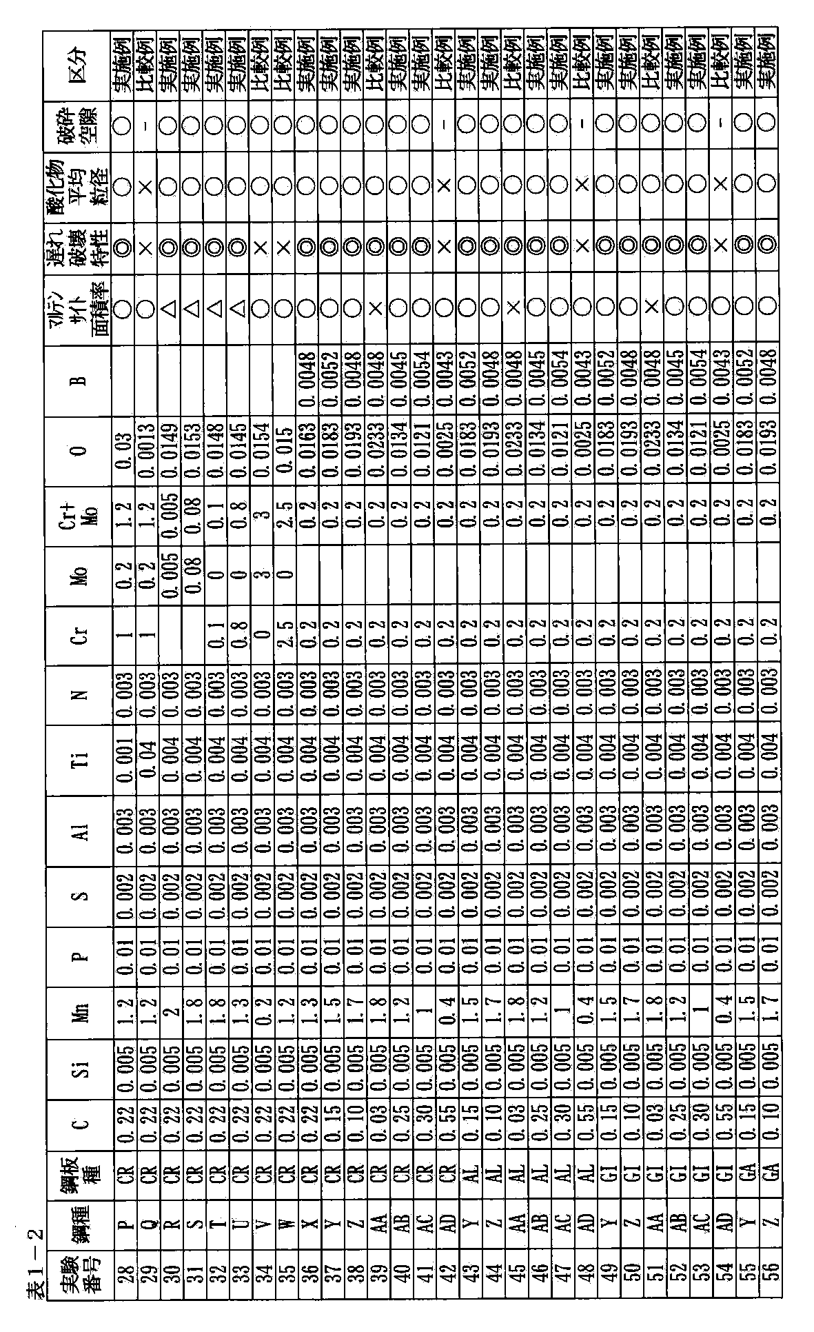
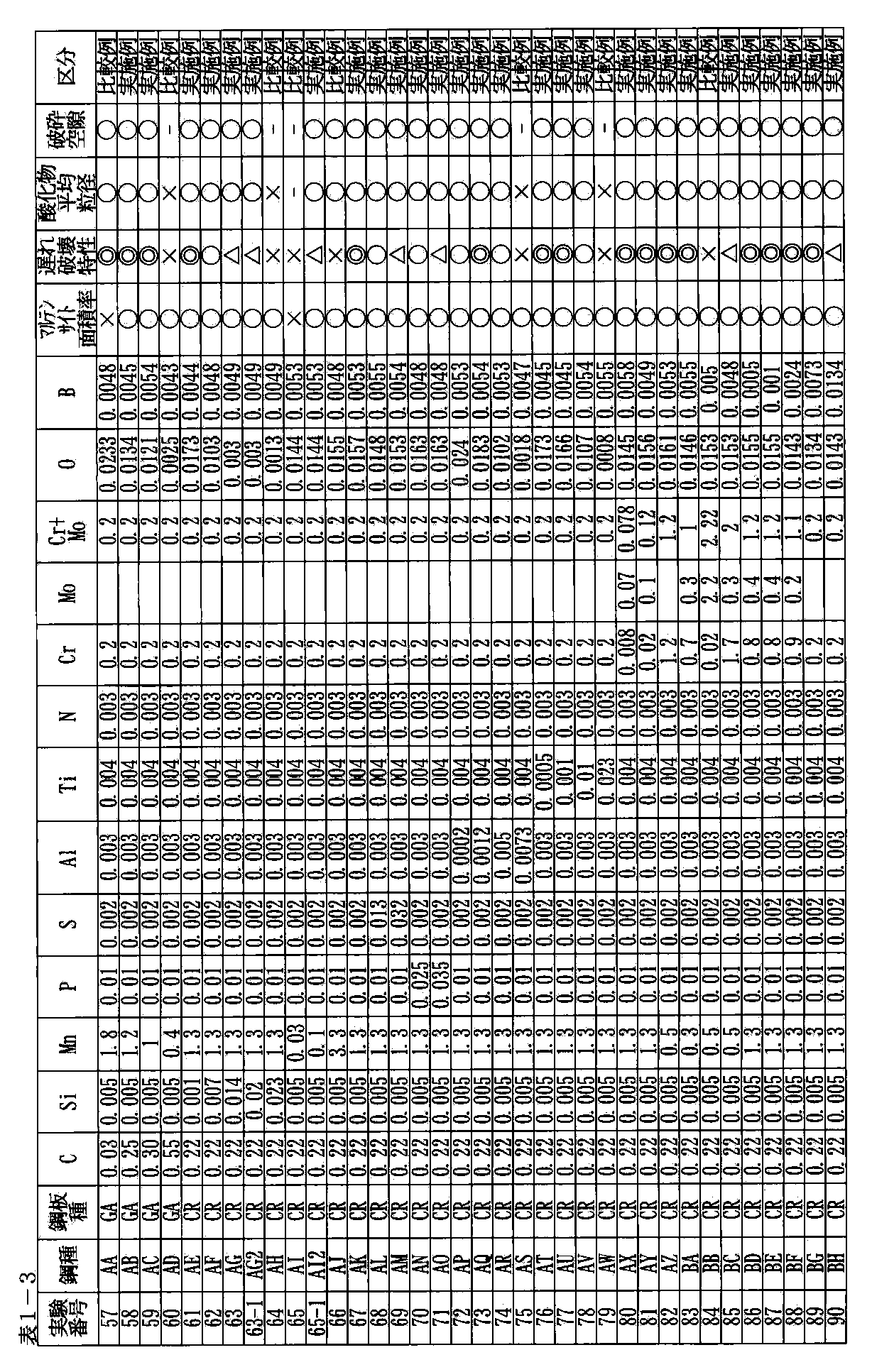
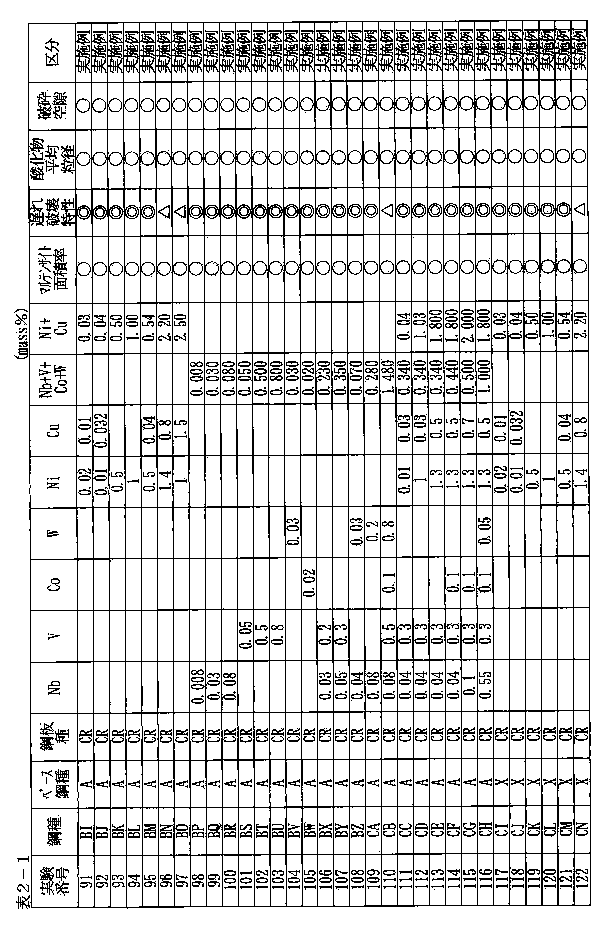
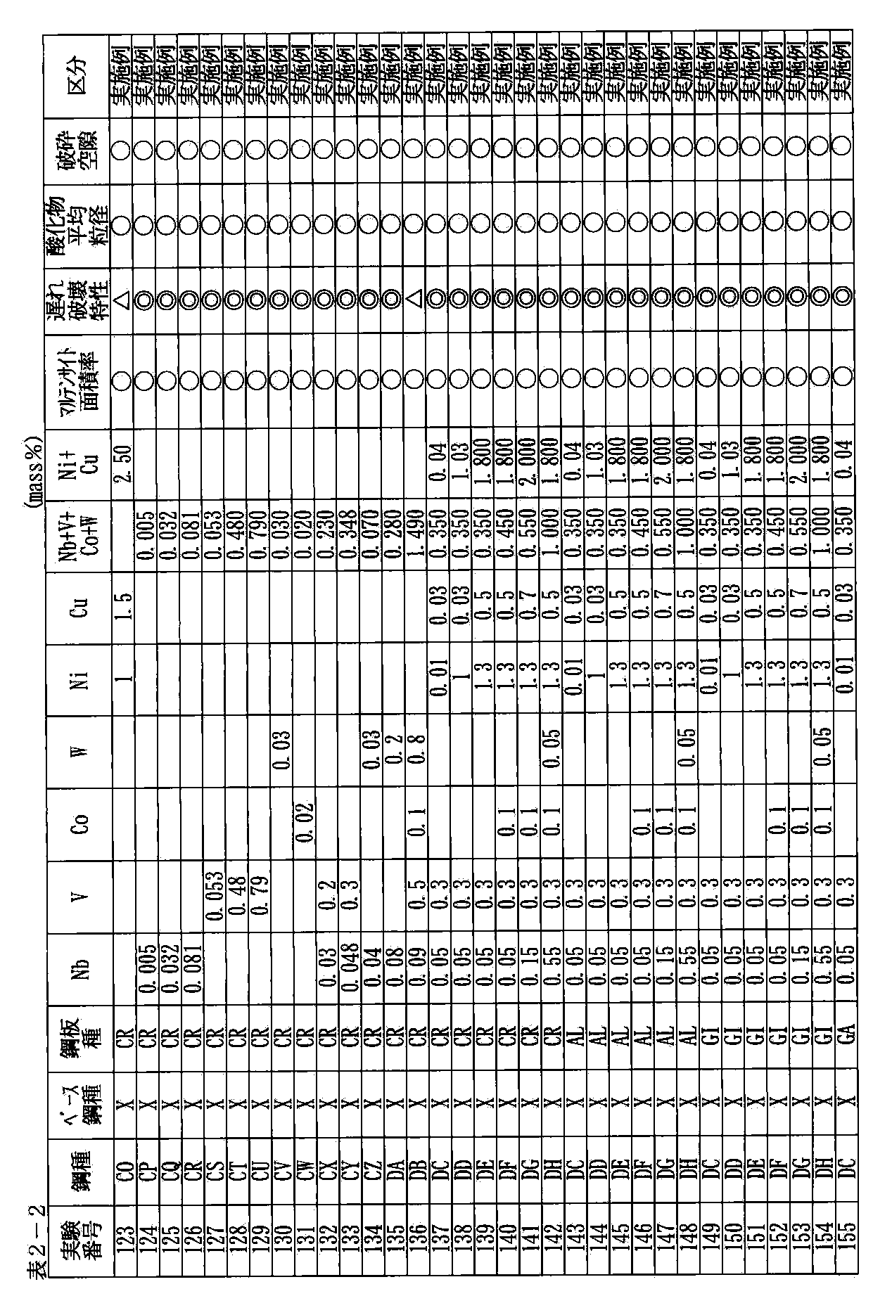
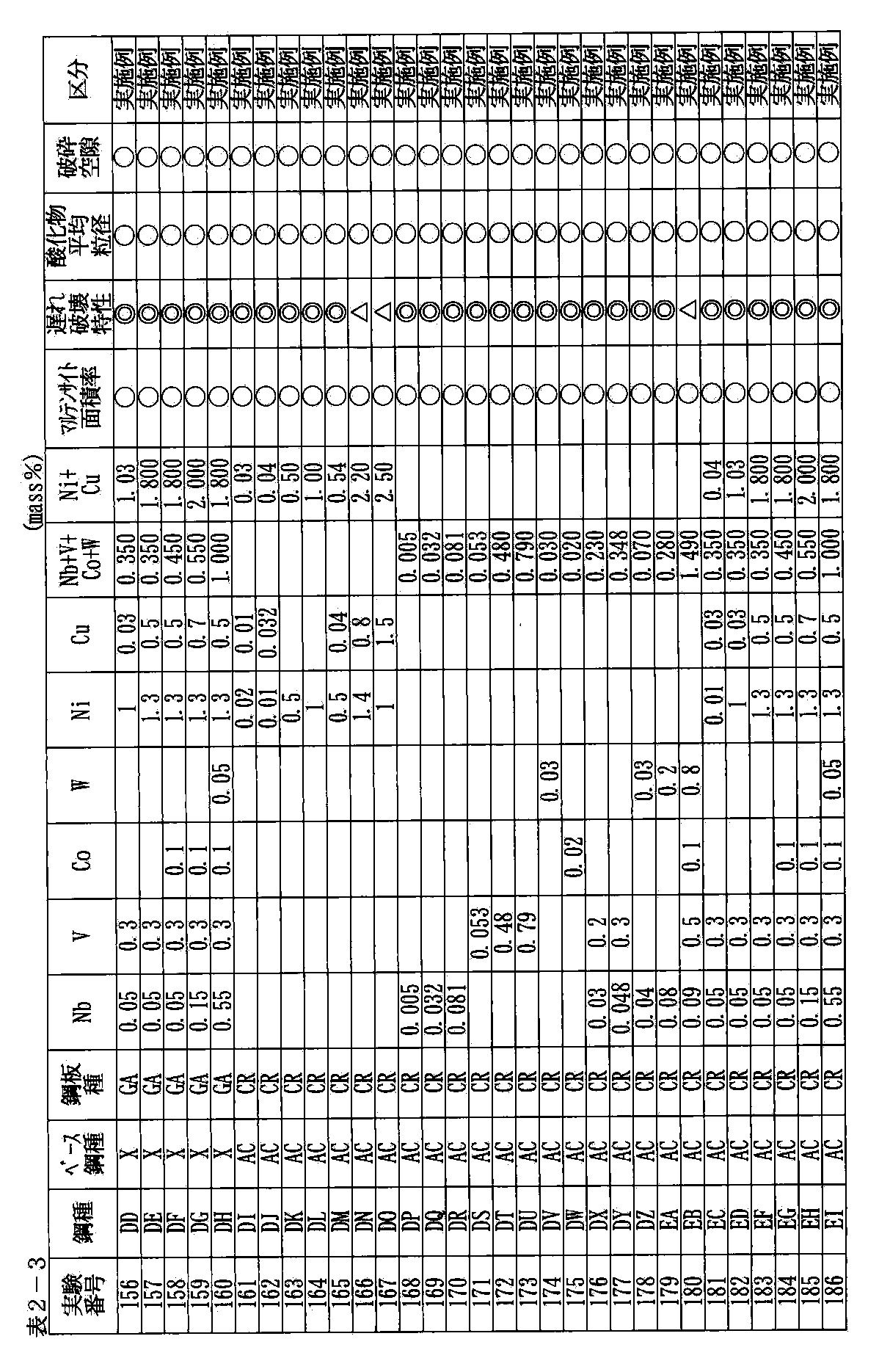
表1−1及び1−2に示した鋼種A、X、ACを用いて圧延条件の検討を行なった。これらのスラブを1050~1350℃に加熱し、熱間圧延にて仕上温度800~900℃、巻取温度450~680℃で熱延鋼板とした。スラブ、粗圧延板、熱延板の厚さおよび粗圧延率、仕上げ圧延率を表3−1及び3−2に示す。その後、一部の熱延鋼板は酸洗を行った後、冷間圧延を施した。冷延板厚さおよび冷延率を表3−1及び3−2に示す。その後、一部の鋼板は連続焼鈍(焼鈍温度720~830℃)を施した。また一部の鋼板について溶融亜鉛めっき(目付け量:片面30~90g/m2)、合金化溶融亜鉛めっき(目付け量:片面30~90g/m2)、溶融アルミ(めっき目付け量:片面30~100g/m2)を連続溶融めっきラインにて施した。鋼板種を表3に合わせて示す。鋼板種の凡例を以下に示す。
HR:熱延鋼板、CR:冷延鋼板、A:焼鈍材、N:焼鈍なし、AL:溶融アルミめっき鋼板、GI:溶融亜鉛めっき鋼板、GA:合金化溶融亜鉛めっき鋼板を意味する。
複合酸化物の平均粒径:
○:平均直径0.1~15μm、
×:平均直径0.1μm未満もしくは15μm超
複合酸化物周囲の破砕空隙:
○:空隙の平均径0.1μm以上
×:空隙の平均径0.1μm未満
○:マルテンサイト面積率90%以上、
△:マルテンサイト面積率80%以上、
×:マルテンサイト面積率80%未満。
10点中の微小クラックの個数の合計:
◎:0個、
○:1個、
△:5個未満、
×:5個以上。

1−1、1−2 酸化物
2 熱延粗圧延
3 延伸された複合酸化物
3−1、3−2 延伸された酸化物
4 熱延仕上げ圧延
5 破砕空隙(水素トラップ能)
5−1.5−2 破砕された酸化物
6 粗大な酸化物
6’ 微細な酸化物
7 延伸された酸化物
8 破砕された酸化物
9 ダイス
10 パンチ
11 ホットスタンプ成形品
12 試験部品
13 ピアス穴位置
Claims (9)
- 質量%で、
C:0.05~0.40%、
Si:0.001~0.02%、
Mn:0.1~3%、
Al:0.0002~0.005%、
Ti:0.0005~0.01%、
O:0.003~0.03%、および
CrとMoのうち1種又は2種の合計で0.005~2%を含有し、
残部Fe及び不可避的不純物の化学成分からなり、かつ平均直径0.1~15μmのFe−Mn系複合酸化物粒子を分散して含有することを特徴とするホットスタンプ用鋼板。 - さらに、質量%で、
(a)B:0.0005~0.01%、
(b)Nb、V、W、Coのうち1種または2種以上を合計で0.005~1%、
(c)Ni、Cuのうち1種または2種を合計で0.005~2%、
で示される(a)~(c)の3群のうち1群または2群以上に含まれる成分を含有することを特徴とする請求項1に記載のホットスタンプ用鋼板。 - 前記複合酸化物粒子の周囲に空隙を有することを特徴とする請求項1または2に記載のホットスタンプ用鋼板。
- 前記複合酸化物粒子の周囲の空隙の平均径が、前記複合酸化物粒子の平均径の10~100%であることを特徴とする請求項1または2に記載のホットスタンプ用鋼板。
- 請求項1または2に記載の鋼板にアルミめっき、亜鉛−アルミめっき、亜鉛めっきの内のいずれかのめっきを施したことを特徴とするホットスタンプ用鋼板。
- 請求項1または2に記載の化学成分の鋳片を熱間圧延する際に粗圧延にて圧延率70%以上、仕上げ圧延にて圧延率70%以上とすることを特徴とするホットスタンプ用鋼板の製造方法。
- 請求項6に記載の熱間圧延した熱延鋼板を酸洗し、圧延率30%以上で冷間圧延を施すことを特徴とするホットスタンプ用鋼板の製造方法。
- 請求項7に記載の冷間圧延した冷延鋼板に焼鈍を施すことを特徴とするホットスタンプ用鋼板の製造方法。
- 請求項1または2のいずれかに記載のホットスタンプ用鋼板を、Ac3以上のオーステナイト域の温度に加熱した後、金型で成形を開始し、成形後に金型中にて冷却して焼入れを行うことを特徴とするホットスタンプ用鋼板を用いた高強度部品の製造方法。
Priority Applications (13)
| Application Number | Priority Date | Filing Date | Title |
|---|---|---|---|
| CA2829032A CA2829032C (en) | 2011-03-09 | 2011-03-09 | Steel sheet for hot stamping use, method of production of same, and method of production of high strength part |
| PCT/JP2011/056124 WO2012120692A1 (ja) | 2011-03-09 | 2011-03-09 | ホットスタンプ用鋼板及びその製造方法と高強度部品の製造方法 |
| BR112013022953-5A BR112013022953B1 (pt) | 2011-03-09 | 2011-03-09 | Chapa de aço para o uso em estampagem a quente, bem como método para produção e uso da mesma |
| EP11860663.1A EP2684972B1 (en) | 2011-03-09 | 2011-03-09 | Steel sheets for hot stamping, method for manufacturing the same, and use for manufacturing high-strength hot-stamped parts |
| JP2011536648A JP4927236B1 (ja) | 2011-03-09 | 2011-03-09 | ホットスタンプ用鋼板及びその製造方法と高強度部品の製造方法 |
| US14/003,881 US10344360B2 (en) | 2011-03-09 | 2011-03-09 | Steel sheet for hot stamping use, method of production of same, and method of production of high strength part |
| CN201610899887.1A CN106435359B (zh) | 2011-03-09 | 2011-03-09 | 热压用钢板及其制造方法和高强度部件的制造方法 |
| RU2013145083/02A RU2557114C2 (ru) | 2011-03-09 | 2011-03-09 | Стальной лист для применения в горячей штамповке, способ его получения и способ получения высокопрочной детали |
| MX2013010195A MX360249B (es) | 2011-03-09 | 2011-03-09 | Laminas de acero para estampado en caliente, metodo para fabricar las mismas y metodo para fabricar partes con alta resistencia. |
| CN201180069136.2A CN103429774B (zh) | 2011-03-09 | 2011-03-09 | 热压用钢板及其制造方法和高强度部件的制造方法 |
| KR1020137022842A KR101536703B1 (ko) | 2011-03-09 | 2011-03-09 | 핫 스탬핑용 강판 및 그의 제조 방법과 고강도 부품의 제조 방법 |
| ZA2013/07339A ZA201307339B (en) | 2011-03-09 | 2013-10-01 | Steel sheets for hot stamping,use, method of production of same, and method of production of high-strength parts. |
| US16/415,556 US20190271063A1 (en) | 2011-03-09 | 2019-05-17 | Steel sheet for hot stamping use, method of production of same, and method of production of high strength part |
Applications Claiming Priority (1)
| Application Number | Priority Date | Filing Date | Title |
|---|---|---|---|
| PCT/JP2011/056124 WO2012120692A1 (ja) | 2011-03-09 | 2011-03-09 | ホットスタンプ用鋼板及びその製造方法と高強度部品の製造方法 |
Related Child Applications (2)
| Application Number | Title | Priority Date | Filing Date |
|---|---|---|---|
| US14/003,881 A-371-Of-International US10344360B2 (en) | 2011-03-09 | 2011-03-09 | Steel sheet for hot stamping use, method of production of same, and method of production of high strength part |
| US16/415,556 Division US20190271063A1 (en) | 2011-03-09 | 2019-05-17 | Steel sheet for hot stamping use, method of production of same, and method of production of high strength part |
Publications (1)
| Publication Number | Publication Date |
|---|---|
| WO2012120692A1 true WO2012120692A1 (ja) | 2012-09-13 |
Family
ID=46261512
Family Applications (1)
| Application Number | Title | Priority Date | Filing Date |
|---|---|---|---|
| PCT/JP2011/056124 Ceased WO2012120692A1 (ja) | 2011-03-09 | 2011-03-09 | ホットスタンプ用鋼板及びその製造方法と高強度部品の製造方法 |
Country Status (11)
| Country | Link |
|---|---|
| US (2) | US10344360B2 (ja) |
| EP (1) | EP2684972B1 (ja) |
| JP (1) | JP4927236B1 (ja) |
| KR (1) | KR101536703B1 (ja) |
| CN (2) | CN103429774B (ja) |
| BR (1) | BR112013022953B1 (ja) |
| CA (1) | CA2829032C (ja) |
| MX (1) | MX360249B (ja) |
| RU (1) | RU2557114C2 (ja) |
| WO (1) | WO2012120692A1 (ja) |
| ZA (1) | ZA201307339B (ja) |
Cited By (12)
| Publication number | Priority date | Publication date | Assignee | Title |
|---|---|---|---|---|
| JP2014118613A (ja) * | 2012-12-18 | 2014-06-30 | Nippon Steel & Sumitomo Metal | 強度と耐水素脆性に優れたホットスタンプ成形体及びその製造方法 |
| WO2014142238A1 (ja) | 2013-03-14 | 2014-09-18 | 新日鐵住金株式会社 | 耐遅れ破壊特性と低温靭性に優れた高強度鋼板、およびそれを用いて製造した高強度部材 |
| WO2015194571A1 (ja) * | 2014-06-20 | 2015-12-23 | 株式会社神戸製鋼所 | 熱間プレス用鋼板、並びに該鋼板を用いた熱間プレス成形品及びその製造方法 |
| JPWO2014196645A1 (ja) * | 2013-06-07 | 2017-02-23 | 新日鐵住金株式会社 | 熱処理鋼材及びその製造方法 |
| JP2018185184A (ja) * | 2017-04-25 | 2018-11-22 | Jfeスチール株式会社 | 高張力鋼板の遅れ破壊特性評価方法 |
| WO2019198781A1 (ja) * | 2018-04-13 | 2019-10-17 | 日本製鉄株式会社 | プレス成形鋼品 |
| JP2020522614A (ja) * | 2017-06-01 | 2020-07-30 | アルセロールミタル | 改善された延性を備えた高強度鋼製部品の製造方法、及び前記方法により得られた部品 |
| WO2020189761A1 (ja) * | 2019-03-20 | 2020-09-24 | 日本製鉄株式会社 | ホットスタンプ成形体 |
| KR20230169265A (ko) | 2021-07-14 | 2023-12-15 | 닛폰세이테츠 가부시키가이샤 | Al 도금 강판, Al 도금 강판의 제조 방법, 및 핫 스탬프 성형체의 제조 방법 |
| WO2024122125A1 (ja) * | 2022-12-09 | 2024-06-13 | 日本製鉄株式会社 | ホットスタンプ成形体 |
| WO2024122121A1 (ja) * | 2022-12-09 | 2024-06-13 | 日本製鉄株式会社 | めっき鋼板 |
| US12312652B2 (en) | 2020-09-01 | 2025-05-27 | Hyundai Steel Company | Material for hot stamping and method of manufacturing the same |
Families Citing this family (31)
| Publication number | Priority date | Publication date | Assignee | Title |
|---|---|---|---|---|
| CA2865910C (en) | 2012-03-07 | 2017-10-17 | Nippon Steel & Sumitomo Metal Corporation | Steel sheet for hot stamping, method for production thereof, and hot stamping steel material |
| EP3115477B1 (en) * | 2014-03-05 | 2020-04-08 | Daido Steel Co.,Ltd. | Age hardening non-heat treated bainitic steel |
| MX379132B (es) * | 2014-05-29 | 2025-03-10 | Nippon Steel Corp | Material de acero tratado con calor y método para producir el mismo. |
| MX379121B (es) * | 2014-05-29 | 2025-03-10 | Nippon Steel Corp | Material de acero tratado térmicamente y método para producirlo. |
| CN104388831B (zh) * | 2014-10-25 | 2016-05-11 | 河北钢铁股份有限公司唐山分公司 | 一种耐低温冲击冷基结构级镀锌钢带的生产方法 |
| KR102034127B1 (ko) * | 2015-04-08 | 2019-10-18 | 닛폰세이테츠 가부시키가이샤 | 열처리 강판 부재 및 그것의 제조 방법 |
| WO2016163467A1 (ja) | 2015-04-08 | 2016-10-13 | 新日鐵住金株式会社 | 熱処理用鋼板 |
| KR101701627B1 (ko) * | 2015-07-17 | 2017-02-01 | 현대제철 주식회사 | 열간 프레스 강판 제조방법 |
| KR101696121B1 (ko) * | 2015-12-23 | 2017-01-13 | 주식회사 포스코 | 내수소지연파괴특성, 내박리성 및 용접성이 우수한 열간성형용 알루미늄-철 합금 도금강판 및 이를 이용한 열간성형 부재 |
| MX370243B (es) * | 2016-05-18 | 2019-12-04 | Nippon Steel Corp Star | Metodo de produccion de producto formado en prensa y linea de produccion de productos formados en prensa. |
| CN106399837B (zh) * | 2016-07-08 | 2018-03-13 | 东北大学 | 热冲压成形用钢材、热冲压成形工艺及热冲压成形构件 |
| KR101830527B1 (ko) | 2016-09-26 | 2018-02-21 | 주식회사 포스코 | 내식성 및 점용접성이 우수한 열간성형용 냉연강판, 열간성형부재 및 그들의 제조방법 |
| MX2019003654A (es) * | 2016-10-04 | 2019-06-10 | Nippon Steel & Sumitomo Metal Corp | Metodo de prensado en caliente y sistema de prensado en caliente. |
| RU2622187C1 (ru) * | 2016-10-31 | 2017-06-13 | Юлия Алексеевна Щепочкина | Конструкционная сталь |
| KR101917478B1 (ko) * | 2016-12-23 | 2019-01-24 | 주식회사 포스코 | 열간 성형품 및 그 제조방법 |
| WO2018221991A1 (ko) * | 2017-06-01 | 2018-12-06 | 주식회사 포스코 | 도금 밀착성이 우수한 열간 프레스 성형 부재용 강판 및 그 제조방법 |
| KR102010048B1 (ko) * | 2017-06-01 | 2019-10-21 | 주식회사 포스코 | 도장 밀착성과 도장 후 내식성이 우수한 열간 프레스 성형 부재용 강판 및 그 제조방법 |
| WO2018221992A1 (ko) * | 2017-06-01 | 2018-12-06 | 주식회사 포스코 | 도장 밀착성과 도장 후 내식성이 우수한 열간 프레스 성형 부재용 강판 및 그 제조방법 |
| WO2018221989A1 (ko) * | 2017-06-01 | 2018-12-06 | 주식회사 포스코 | 수소지연파괴 저항성이 우수한 열간 프레스 성형 부재용 강판 및 그 제조방법 |
| KR102021200B1 (ko) * | 2017-06-27 | 2019-09-11 | 현대제철 주식회사 | 핫 스탬핑 부품 및 이의 제조방법 |
| EP3437750A1 (en) * | 2017-08-02 | 2019-02-06 | Autotech Engineering A.I.E. | Press method for coated steels |
| RU2650951C1 (ru) * | 2017-11-27 | 2018-04-18 | Юлия Алексеевна Щепочкина | Сталь |
| RU2650943C1 (ru) * | 2017-12-19 | 2018-04-18 | Юлия Алексеевна Щепочкина | Сталь |
| KR102110679B1 (ko) * | 2018-09-28 | 2020-05-13 | 현대제철 주식회사 | 핫 스탬핑 부품 및 그 제조방법 |
| KR102179214B1 (ko) * | 2018-11-30 | 2020-11-16 | 주식회사 포스코 | 법랑용 냉연 강판 및 그 제조방법 |
| KR102180811B1 (ko) | 2018-12-03 | 2020-11-20 | 주식회사 포스코 | 수소취성에 대한 저항성이 우수한 열간 프레스 성형 부재 및 그 제조방법 |
| JP7684386B2 (ja) * | 2020-09-01 | 2025-05-27 | ヒュンダイ スチール カンパニー | ホットスタンピング用素材及びその製造方法 |
| WO2022050501A1 (ko) | 2020-09-01 | 2022-03-10 | 현대제철 주식회사 | 핫스탬핑용 소재 및 그 제조방법 |
| WO2022050500A1 (ko) * | 2020-09-01 | 2022-03-10 | 현대제철 주식회사 | 핫스탬핑용 소재 및 그 제조방법 |
| CN115673074A (zh) * | 2021-07-28 | 2023-02-03 | 宝山钢铁股份有限公司 | 一种1500MPa以上的铝硅镀层热冲压钢零件制备方法及零件 |
| CN118854169B (zh) * | 2024-09-23 | 2025-02-11 | 攀钢集团研究院有限公司 | 一种1.0GPa级免镀层热冲压成形钢及其制备方法 |
Citations (7)
| Publication number | Priority date | Publication date | Assignee | Title |
|---|---|---|---|---|
| JPS6415320A (en) * | 1987-07-08 | 1989-01-19 | Nippon Steel Corp | Production of high tensile steel for low temperature use having excellent toughness of weld zone |
| JPH1096031A (ja) | 1996-09-20 | 1998-04-14 | Sumitomo Metal Ind Ltd | 高炭素薄鋼板の製造方法および部品の製造方法 |
| JP2005068548A (ja) | 2003-02-28 | 2005-03-17 | Nippon Steel Corp | 耐水素脆化に優れた高強度薄鋼板及びその製造方法 |
| JP2006009116A (ja) | 2004-06-29 | 2006-01-12 | Nippon Steel Corp | 熱間プレス用鋼板 |
| JP2006051543A (ja) | 2004-07-15 | 2006-02-23 | Nippon Steel Corp | 冷延、熱延鋼板もしくはAl系、Zn系めっき鋼板を使用した高強度自動車部材の熱間プレス方法および熱間プレス部品 |
| WO2008038474A1 (fr) | 2006-09-27 | 2008-04-03 | Nippon Steel Corporation | Tôle en acier pour émaillage présentant une très faible propension à l'écaillage et procédé pour la produire |
| JP2008284610A (ja) * | 2007-04-20 | 2008-11-27 | Nippon Steel Corp | 高強度部品の製造方法および高強度部品 |
Family Cites Families (11)
| Publication number | Priority date | Publication date | Assignee | Title |
|---|---|---|---|---|
| JPS5867297A (ja) | 1981-10-15 | 1983-04-21 | 松下電器産業株式会社 | コ−ドリ−ル付アイロン |
| TW504519B (en) * | 1999-11-08 | 2002-10-01 | Kawasaki Steel Co | Hot dip galvanized steel plate excellent in balance of strength and ductility and in adhesiveness between steel and plating layer, and method for producing the same |
| ES2247383T3 (es) | 2001-10-29 | 2006-03-01 | Nippon Steel Corporation | Lamina de acero para el esmaltado vitreo excelente en sus posibilidades de ser trabajada y de resistencia a la formacion de escamas, y metodo para producir la misma. |
| US6709535B2 (en) * | 2002-05-30 | 2004-03-23 | Kobe Steel, Ltd. | Superhigh-strength dual-phase steel sheet of excellent fatigue characteristic in a spot welded joint |
| US7687152B2 (en) * | 2003-04-10 | 2010-03-30 | Nippon Steel Corporation | High strength molten zinc plated steel sheet and process of production of same |
| US20090047168A1 (en) * | 2005-11-09 | 2009-02-19 | Hidekuni Murakami | Continuously Cast Enameled Steel Sheet Remarkably Excellent in Fishscale Resistance and Method of Production of the Same |
| WO2007064172A1 (en) | 2005-12-01 | 2007-06-07 | Posco | Steel sheet for hot press forming having excellent heat treatment and impact property, hot press parts made of it and the method for manufacturing thereof |
| KR100878614B1 (ko) * | 2005-12-01 | 2009-01-15 | 주식회사 포스코 | 열처리 경화형 초고강도 강판, 이를 이용한 열처리 경화형부재와 그 제조방법 |
| JP4983082B2 (ja) * | 2006-04-26 | 2012-07-25 | 住友金属工業株式会社 | 高強度鋼材及びその製造方法 |
| JP5023871B2 (ja) | 2007-08-03 | 2012-09-12 | 住友金属工業株式会社 | 熱間プレス鋼板部材の製造方法 |
| US8460800B2 (en) * | 2009-03-31 | 2013-06-11 | Kobe Steel, Ltd. | High-strength cold-rolled steel sheet excellent in bending workability |
-
2011
- 2011-03-09 US US14/003,881 patent/US10344360B2/en active Active
- 2011-03-09 BR BR112013022953-5A patent/BR112013022953B1/pt not_active IP Right Cessation
- 2011-03-09 JP JP2011536648A patent/JP4927236B1/ja active Active
- 2011-03-09 CA CA2829032A patent/CA2829032C/en not_active Expired - Fee Related
- 2011-03-09 CN CN201180069136.2A patent/CN103429774B/zh active Active
- 2011-03-09 WO PCT/JP2011/056124 patent/WO2012120692A1/ja not_active Ceased
- 2011-03-09 RU RU2013145083/02A patent/RU2557114C2/ru not_active IP Right Cessation
- 2011-03-09 MX MX2013010195A patent/MX360249B/es active IP Right Grant
- 2011-03-09 CN CN201610899887.1A patent/CN106435359B/zh active Active
- 2011-03-09 KR KR1020137022842A patent/KR101536703B1/ko active Active
- 2011-03-09 EP EP11860663.1A patent/EP2684972B1/en active Active
-
2013
- 2013-10-01 ZA ZA2013/07339A patent/ZA201307339B/en unknown
-
2019
- 2019-05-17 US US16/415,556 patent/US20190271063A1/en not_active Abandoned
Patent Citations (7)
| Publication number | Priority date | Publication date | Assignee | Title |
|---|---|---|---|---|
| JPS6415320A (en) * | 1987-07-08 | 1989-01-19 | Nippon Steel Corp | Production of high tensile steel for low temperature use having excellent toughness of weld zone |
| JPH1096031A (ja) | 1996-09-20 | 1998-04-14 | Sumitomo Metal Ind Ltd | 高炭素薄鋼板の製造方法および部品の製造方法 |
| JP2005068548A (ja) | 2003-02-28 | 2005-03-17 | Nippon Steel Corp | 耐水素脆化に優れた高強度薄鋼板及びその製造方法 |
| JP2006009116A (ja) | 2004-06-29 | 2006-01-12 | Nippon Steel Corp | 熱間プレス用鋼板 |
| JP2006051543A (ja) | 2004-07-15 | 2006-02-23 | Nippon Steel Corp | 冷延、熱延鋼板もしくはAl系、Zn系めっき鋼板を使用した高強度自動車部材の熱間プレス方法および熱間プレス部品 |
| WO2008038474A1 (fr) | 2006-09-27 | 2008-04-03 | Nippon Steel Corporation | Tôle en acier pour émaillage présentant une très faible propension à l'écaillage et procédé pour la produire |
| JP2008284610A (ja) * | 2007-04-20 | 2008-11-27 | Nippon Steel Corp | 高強度部品の製造方法および高強度部品 |
Non-Patent Citations (1)
| Title |
|---|
| See also references of EP2684972A4 |
Cited By (34)
| Publication number | Priority date | Publication date | Assignee | Title |
|---|---|---|---|---|
| JP2014118613A (ja) * | 2012-12-18 | 2014-06-30 | Nippon Steel & Sumitomo Metal | 強度と耐水素脆性に優れたホットスタンプ成形体及びその製造方法 |
| RU2625366C2 (ru) * | 2013-03-14 | 2017-07-13 | Ниппон Стил Энд Сумитомо Метал Корпорейшн | Высокопрочный стальной лист с повышенной устойчивостью к замедленному разрушению и низкотемпературной ударной вязкостью и высокопрочная деталь, изготовленная с его использованием |
| WO2014142238A1 (ja) | 2013-03-14 | 2014-09-18 | 新日鐵住金株式会社 | 耐遅れ破壊特性と低温靭性に優れた高強度鋼板、およびそれを用いて製造した高強度部材 |
| KR20150119072A (ko) | 2013-03-14 | 2015-10-23 | 신닛테츠스미킨 카부시키카이샤 | 내 지연 파괴 특성과 저온 인성이 우수한 고강도 강판 및 그것을 사용하여 제조한 고강도 부재 |
| CN105189798A (zh) * | 2013-03-14 | 2015-12-23 | 新日铁住金株式会社 | 耐延迟断裂特性和低温韧性优异的高强度钢板、和使用其制造的高强度构件 |
| US9353424B2 (en) | 2013-03-14 | 2016-05-31 | Nippon Steel & Sumitomo Metal Corporation | High strength steel sheet excellent in delayed fracture resistance and low temperature toughness, and high strength member manufactured using the same |
| TWI550103B (zh) * | 2013-03-14 | 2016-09-21 | Nippon Steel & Sumitomo Metal Corp | 具優異耐延遲破壞特性與低溫韌性之高強度鋼板、及使用其製成之高強度構件 |
| JPWO2014142238A1 (ja) * | 2013-03-14 | 2017-02-16 | 新日鐵住金株式会社 | 耐遅れ破壊特性と低温靭性に優れた高強度鋼板、およびそれを用いて製造した高強度部材 |
| US10435761B2 (en) | 2013-06-07 | 2019-10-08 | Nippon Steel Corporation | Heat-treated steel material and method of manufacturing the same |
| JPWO2014196645A1 (ja) * | 2013-06-07 | 2017-02-23 | 新日鐵住金株式会社 | 熱処理鋼材及びその製造方法 |
| EP3006586A4 (en) * | 2013-06-07 | 2017-03-08 | Nippon Steel & Sumitomo Metal Corporation | Heat-treated steel material and method for producing same |
| WO2015194571A1 (ja) * | 2014-06-20 | 2015-12-23 | 株式会社神戸製鋼所 | 熱間プレス用鋼板、並びに該鋼板を用いた熱間プレス成形品及びその製造方法 |
| JP2018185184A (ja) * | 2017-04-25 | 2018-11-22 | Jfeスチール株式会社 | 高張力鋼板の遅れ破壊特性評価方法 |
| US11473166B2 (en) | 2017-06-01 | 2022-10-18 | Arcelormittal | Method for producing high-strength steel parts with improved ductility, and parts obtained by said method |
| US11976342B2 (en) | 2017-06-01 | 2024-05-07 | Arcelor Mittal | Method for producing high-strength steel parts with improved ductility, and parts obtained by said method |
| JP7506721B2 (ja) | 2017-06-01 | 2024-06-26 | アルセロールミタル | 改善された延性を備えた高強度鋼製部品の製造方法、及び前記方法により得られた部品 |
| JP2020522614A (ja) * | 2017-06-01 | 2020-07-30 | アルセロールミタル | 改善された延性を備えた高強度鋼製部品の製造方法、及び前記方法により得られた部品 |
| JP2022174173A (ja) * | 2017-06-01 | 2022-11-22 | アルセロールミタル | 改善された延性を備えた高強度鋼製部品の製造方法、及び前記方法により得られた部品 |
| JP7735485B2 (ja) | 2017-06-01 | 2025-09-08 | アルセロールミタル | 改善された延性を備えた高強度鋼製部品の製造方法、及び前記方法により得られた部品 |
| JP7139361B2 (ja) | 2017-06-01 | 2022-09-20 | アルセロールミタル | 改善された延性を備えた高強度鋼製部品の製造方法、及び前記方法により得られた部品 |
| JP2024123090A (ja) * | 2017-06-01 | 2024-09-10 | アルセロールミタル | 改善された延性を備えた高強度鋼製部品の製造方法、及び前記方法により得られた部品 |
| WO2019198781A1 (ja) * | 2018-04-13 | 2019-10-17 | 日本製鉄株式会社 | プレス成形鋼品 |
| CN111989509A (zh) * | 2018-04-13 | 2020-11-24 | 日本制铁株式会社 | 压制成型钢制品 |
| CN111989509B (zh) * | 2018-04-13 | 2023-06-20 | 日本制铁株式会社 | 压制成型钢制品 |
| JP6628019B1 (ja) * | 2018-04-13 | 2020-01-08 | 日本製鉄株式会社 | プレス成形鋼品 |
| WO2020189761A1 (ja) * | 2019-03-20 | 2020-09-24 | 日本製鉄株式会社 | ホットスタンプ成形体 |
| JP7151871B2 (ja) | 2019-03-20 | 2022-10-12 | 日本製鉄株式会社 | ホットスタンプ成形体 |
| JPWO2020189761A1 (ja) * | 2019-03-20 | 2021-11-18 | 日本製鉄株式会社 | ホットスタンプ成形体 |
| US12312652B2 (en) | 2020-09-01 | 2025-05-27 | Hyundai Steel Company | Material for hot stamping and method of manufacturing the same |
| KR20230169265A (ko) | 2021-07-14 | 2023-12-15 | 닛폰세이테츠 가부시키가이샤 | Al 도금 강판, Al 도금 강판의 제조 방법, 및 핫 스탬프 성형체의 제조 방법 |
| WO2024122125A1 (ja) * | 2022-12-09 | 2024-06-13 | 日本製鉄株式会社 | ホットスタンプ成形体 |
| WO2024122121A1 (ja) * | 2022-12-09 | 2024-06-13 | 日本製鉄株式会社 | めっき鋼板 |
| JPWO2024122121A1 (ja) * | 2022-12-09 | 2024-06-13 | ||
| JP7801645B2 (ja) | 2022-12-09 | 2026-01-19 | 日本製鉄株式会社 | めっき鋼板 |
Also Published As
| Publication number | Publication date |
|---|---|
| CN103429774B (zh) | 2016-11-02 |
| EP2684972A4 (en) | 2014-10-29 |
| CN103429774A (zh) | 2013-12-04 |
| KR101536703B1 (ko) | 2015-07-14 |
| JPWO2012120692A1 (ja) | 2014-07-07 |
| KR20130121965A (ko) | 2013-11-06 |
| CA2829032C (en) | 2016-05-03 |
| JP4927236B1 (ja) | 2012-05-09 |
| US20130340899A1 (en) | 2013-12-26 |
| US10344360B2 (en) | 2019-07-09 |
| CN106435359B (zh) | 2018-07-31 |
| BR112013022953B1 (pt) | 2019-03-19 |
| BR112013022953A2 (pt) | 2016-12-06 |
| MX360249B (es) | 2018-10-26 |
| EP2684972A1 (en) | 2014-01-15 |
| MX2013010195A (es) | 2013-09-26 |
| EP2684972B1 (en) | 2017-09-27 |
| CA2829032A1 (en) | 2012-09-13 |
| CN106435359A (zh) | 2017-02-22 |
| RU2013145083A (ru) | 2015-04-20 |
| RU2557114C2 (ru) | 2015-07-20 |
| US20190271063A1 (en) | 2019-09-05 |
| ZA201307339B (en) | 2014-06-25 |
Similar Documents
| Publication | Publication Date | Title |
|---|---|---|
| JP4927236B1 (ja) | ホットスタンプ用鋼板及びその製造方法と高強度部品の製造方法 | |
| US10550446B2 (en) | High-strength steel sheet, high-strength hot-dip galvanized steel sheet, high-strength hot-dip aluminum-coated steel sheet, and high-strength electrogalvanized steel sheet, and methods for manufacturing same | |
| US8840834B2 (en) | High-strength steel sheet and method for manufacturing the same | |
| JP7736476B2 (ja) | 高強度部材、高強度部材の製造方法及び高強度部材用鋼板の製造方法 | |
| CN102859020B (zh) | 热处理钢材及其制造方法以及其原材料钢材 | |
| JP5447741B1 (ja) | 鋼板、めっき鋼板、及びそれらの製造方法 | |
| EP3214199B1 (en) | High-strength steel sheet, high-strength hot-dip galvanized steel sheet, high-strength hot-dip aluminum-coated steel sheet, and high-strength electrogalvanized steel sheet, and methods for manufacturing same | |
| US20110030854A1 (en) | High-strength steel sheet and method for manufacturing the same | |
| JP6795042B2 (ja) | ホットスタンプ成形体及びその製造方法 | |
| CN112930413A (zh) | 高强度钢板及其制造方法 | |
| JP5126844B2 (ja) | 熱間プレス用鋼板およびその製造方法ならびに熱間プレス鋼板部材の製造方法 | |
| JP2017048412A (ja) | 溶融亜鉛めっき鋼板、合金化溶融亜鉛めっき鋼板、およびそれらの製造方法 | |
| CN114438418A (zh) | 热成形构件及其制造方法 | |
| WO2018088421A1 (ja) | 高強度冷延薄鋼板および高強度冷延薄鋼板の製造方法 | |
| CN115151673B (zh) | 钢板、构件和它们的制造方法 | |
| TW201500560A (zh) | 氮化處理用鋼板及其製造方法 | |
| JP2006104526A (ja) | 高強度部品の製造方法と高強度部品 | |
| JP4551169B2 (ja) | 高強度部品の製造方法 | |
| JP4317506B2 (ja) | 高強度部品の製造方法 | |
| JP4987272B2 (ja) | 高強度部品の製造方法および高強度部品 | |
| WO2023162190A1 (ja) | 鋼板、部材、それらの製造方法、冷延鋼板用熱延鋼板の製造方法及び冷延鋼板の製造方法 | |
| JP2006104527A (ja) | 高強度部品の製造方法と高強度部品 | |
| JP4551300B2 (ja) | 高強度部品の製造方法 | |
| JP7687516B2 (ja) | 鋼板、部材、それらの製造方法、冷延鋼板用熱延鋼板の製造方法及び冷延鋼板の製造方法 | |
| EP4640883A1 (en) | Cold-rolled steel sheet and manufacturing method therefor |
Legal Events
| Date | Code | Title | Description |
|---|---|---|---|
| ENP | Entry into the national phase |
Ref document number: 2011536648 Country of ref document: JP Kind code of ref document: A |
|
| 121 | Ep: the epo has been informed by wipo that ep was designated in this application |
Ref document number: 11860663 Country of ref document: EP Kind code of ref document: A1 |
|
| ENP | Entry into the national phase |
Ref document number: 20137022842 Country of ref document: KR Kind code of ref document: A |
|
| ENP | Entry into the national phase |
Ref document number: 2829032 Country of ref document: CA |
|
| WWE | Wipo information: entry into national phase |
Ref document number: MX/A/2013/010195 Country of ref document: MX |
|
| NENP | Non-entry into the national phase |
Ref country code: DE |
|
| WWE | Wipo information: entry into national phase |
Ref document number: 1301004972 Country of ref document: TH Ref document number: 14003881 Country of ref document: US |
|
| REEP | Request for entry into the european phase |
Ref document number: 2011860663 Country of ref document: EP |
|
| WWE | Wipo information: entry into national phase |
Ref document number: 2011860663 Country of ref document: EP |
|
| ENP | Entry into the national phase |
Ref document number: 2013145083 Country of ref document: RU Kind code of ref document: A |
|
| REG | Reference to national code |
Ref country code: BR Ref legal event code: B01A Ref document number: 112013022953 Country of ref document: BR |
|
| ENP | Entry into the national phase |
Ref document number: 112013022953 Country of ref document: BR Kind code of ref document: A2 Effective date: 20130906 |