WO2012120656A1 - 通話支援装置、通話支援方法 - Google Patents
通話支援装置、通話支援方法 Download PDFInfo
- Publication number
- WO2012120656A1 WO2012120656A1 PCT/JP2011/055422 JP2011055422W WO2012120656A1 WO 2012120656 A1 WO2012120656 A1 WO 2012120656A1 JP 2011055422 W JP2011055422 W JP 2011055422W WO 2012120656 A1 WO2012120656 A1 WO 2012120656A1
- Authority
- WO
- WIPO (PCT)
- Prior art keywords
- speaker
- terminal
- customer
- voice
- hold
- Prior art date
- Legal status (The legal status is an assumption and is not a legal conclusion. Google has not performed a legal analysis and makes no representation as to the accuracy of the status listed.)
- Ceased
Links
Images










Classifications
-
- G—PHYSICS
- G10—MUSICAL INSTRUMENTS; ACOUSTICS
- G10L—SPEECH ANALYSIS TECHNIQUES OR SPEECH SYNTHESIS; SPEECH RECOGNITION; SPEECH OR VOICE PROCESSING TECHNIQUES; SPEECH OR AUDIO CODING OR DECODING
- G10L21/00—Speech or voice signal processing techniques to produce another audible or non-audible signal, e.g. visual or tactile, in order to modify its quality or its intelligibility
- G10L21/06—Transformation of speech into a non-audible representation, e.g. speech visualisation or speech processing for tactile aids
- G10L21/16—Transforming into a non-visible representation
-
- G—PHYSICS
- G10—MUSICAL INSTRUMENTS; ACOUSTICS
- G10L—SPEECH ANALYSIS TECHNIQUES OR SPEECH SYNTHESIS; SPEECH RECOGNITION; SPEECH OR VOICE PROCESSING TECHNIQUES; SPEECH OR AUDIO CODING OR DECODING
- G10L25/00—Speech or voice analysis techniques not restricted to a single one of groups G10L15/00 - G10L21/00
- G10L25/48—Speech or voice analysis techniques not restricted to a single one of groups G10L15/00 - G10L21/00 specially adapted for particular use
-
- H—ELECTRICITY
- H04—ELECTRIC COMMUNICATION TECHNIQUE
- H04M—TELEPHONIC COMMUNICATION
- H04M3/00—Automatic or semi-automatic exchanges
- H04M3/42—Systems providing special services or facilities to subscribers
- H04M3/42221—Conversation recording systems
-
- H—ELECTRICITY
- H04—ELECTRIC COMMUNICATION TECHNIQUE
- H04M—TELEPHONIC COMMUNICATION
- H04M3/00—Automatic or semi-automatic exchanges
- H04M3/42—Systems providing special services or facilities to subscribers
- H04M3/50—Centralised arrangements for answering calls; Centralised arrangements for recording messages for absent or busy subscribers ; Centralised arrangements for recording messages
- H04M3/51—Centralised call answering arrangements requiring operator intervention, e.g. call or contact centers for telemarketing
-
- G—PHYSICS
- G10—MUSICAL INSTRUMENTS; ACOUSTICS
- G10L—SPEECH ANALYSIS TECHNIQUES OR SPEECH SYNTHESIS; SPEECH RECOGNITION; SPEECH OR VOICE PROCESSING TECHNIQUES; SPEECH OR AUDIO CODING OR DECODING
- G10L15/00—Speech recognition
- G10L15/28—Constructional details of speech recognition systems
- G10L15/30—Distributed recognition, e.g. in client-server systems, for mobile phones or network applications
-
- G—PHYSICS
- G10—MUSICAL INSTRUMENTS; ACOUSTICS
- G10L—SPEECH ANALYSIS TECHNIQUES OR SPEECH SYNTHESIS; SPEECH RECOGNITION; SPEECH OR VOICE PROCESSING TECHNIQUES; SPEECH OR AUDIO CODING OR DECODING
- G10L15/00—Speech recognition
- G10L15/08—Speech classification or search
- G10L2015/088—Word spotting
-
- G—PHYSICS
- G10—MUSICAL INSTRUMENTS; ACOUSTICS
- G10L—SPEECH ANALYSIS TECHNIQUES OR SPEECH SYNTHESIS; SPEECH RECOGNITION; SPEECH OR VOICE PROCESSING TECHNIQUES; SPEECH OR AUDIO CODING OR DECODING
- G10L25/00—Speech or voice analysis techniques not restricted to a single one of groups G10L15/00 - G10L21/00
- G10L25/48—Speech or voice analysis techniques not restricted to a single one of groups G10L15/00 - G10L21/00 specially adapted for particular use
- G10L25/51—Speech or voice analysis techniques not restricted to a single one of groups G10L15/00 - G10L21/00 specially adapted for particular use for comparison or discrimination
- G10L25/63—Speech or voice analysis techniques not restricted to a single one of groups G10L15/00 - G10L21/00 specially adapted for particular use for comparison or discrimination for estimating an emotional state
-
- H—ELECTRICITY
- H04—ELECTRIC COMMUNICATION TECHNIQUE
- H04M—TELEPHONIC COMMUNICATION
- H04M2201/00—Electronic components, circuits, software, systems or apparatus used in telephone systems
- H04M2201/40—Electronic components, circuits, software, systems or apparatus used in telephone systems using speech recognition
-
- H—ELECTRICITY
- H04—ELECTRIC COMMUNICATION TECHNIQUE
- H04M—TELEPHONIC COMMUNICATION
- H04M2203/00—Aspects of automatic or semi-automatic exchanges
- H04M2203/20—Aspects of automatic or semi-automatic exchanges related to features of supplementary services
- H04M2203/2038—Call context notifications
-
- H—ELECTRICITY
- H04—ELECTRIC COMMUNICATION TECHNIQUE
- H04M—TELEPHONIC COMMUNICATION
- H04M2203/00—Aspects of automatic or semi-automatic exchanges
- H04M2203/35—Aspects of automatic or semi-automatic exchanges related to information services provided via a voice call
- H04M2203/352—In-call/conference information service
-
- H—ELECTRICITY
- H04—ELECTRIC COMMUNICATION TECHNIQUE
- H04M—TELEPHONIC COMMUNICATION
- H04M2203/00—Aspects of automatic or semi-automatic exchanges
- H04M2203/40—Aspects of automatic or semi-automatic exchanges related to call centers
- H04M2203/401—Performance feedback
Definitions
- the present invention relates to a call support device and a call support method for supporting a call.
- a technology for measuring the customer's psychological state from the voice of the customer during the call and notifying the operator of the customer's psychological state It has been known.
- a technique for grasping the psychological state for example, a technique for determining a customer's dissatisfaction level based on the number of dissatisfied keywords appearing during a call, a voice information obtained by voice recognition processing of a customer's voice, language information, speech speed, A technique for discriminating customer emotions using prosodic features such as volume is known.
- a technique for judging a user's emotion based on the association between words and emotions is known.
- the customer's psychological state can be accurately expressed from the voice during the call with the operator as in the past. It is difficult to grasp. Therefore, in order to accurately measure the customer's psychological state, it is desirable to have a technology that acquires the customer's voice that the customer uttered without being aware of the operator and uses the acquired voice to measure the customer's psychological state. ing.
- the hold side (customer side) can release the hold by voice, the technology related to the release of the private branch exchange that records the message, and the hold side (operator by the request from the hold side during the hold)
- a technique is known in which the side) is restored to a non-holding state and the holding side is called.
- a technique in which a holdee leaves a message to the holdee and disconnects and a technique in which the holdee's voice is sent to a monitor speaker when the hold state has passed for a certain period of time. Note that any of the above-described techniques related to the release of the hold is intended to intentionally transmit the intention or request to the hold side.
- the present invention analyzes the characteristics of a voice uttered by a customer without being conscious of the operator in the hold state instructed by the operator during a call, measures the customer's psychological state based on the analysis result, and measures the psychological state It is an object of the present invention to provide a call support device and a call support method that improve the accuracy of communication.
- a call support device for supporting the second speaker In communication performed between the first terminal used by the first speaker and the second terminal used by the second speaker, which is one of the embodiments, a call support device for supporting the second speaker is provided. And analyzing means and instruction means.
- the analysis means detects a hold state of the communication started by the hold notification transmitted by the second terminal, and analyzes characteristics of the voice information of the first speaker in the hold state.
- the instructing means outputs determination information related to the first speaker based on the feature of the voice information of the first speaker to the second terminal.
- the feature of the voice uttered by the customer is analyzed, and the psychological state of the customer is measured based on the analysis result. There is an effect of improving the accuracy of measurement.
- FIG. 6 is a diagram illustrating an example of an operation of an analysis unit according to the first embodiment.
- FIG. It is a figure which shows one Example of the operation
- FIG. It is a figure which shows the time chart of one Example of the method of analyzing the characteristic of the customer's voice of Embodiment 1.
- FIG. It is a figure which shows one Example of the data structure of the content of a message, and correspondence information. It is a figure which shows one Example of the function of the control part of Embodiment 2, and a memory
- FIG. 10 is a diagram illustrating an example of an operation of an analysis unit according to the second embodiment. It is a figure which shows one Example of the data structure of dissatisfaction word detection information and dissatisfaction word keyword information. It is a figure which shows one Example of operation
- FIG. 10 is a diagram illustrating an example of an operation of an analysis unit according to the second embodiment. It is a figure which shows one Example of the data structure of dissatisfaction word detection information and dissatisfaction word keyword information. It is a figure which shows one Example of operation
- Embodiment 1 acquires the voice which the customer uttered in the hold state instructed by the operator during the call, analyzes the characteristics of the acquired voice, and measures the customer's psychological state based on the analysis result, The accuracy of measuring the psychological state of can be improved. That is, since the customer thinks that his / her conversation has not been transmitted to the operator during the hold, it is assumed that the customer expresses his / her real feelings such as dissatisfaction in a simple manner such as a single word, a sigh, a sigh, and the like.
- the customer's psychological state is measured by acquiring the customer's voice in the on-hold state that has not been used to measure the customer's psychological state in the past, and performing analysis processing described later on the characteristics of the acquired voice. Accuracy can be improved. Further, by improving the accuracy of measuring the customer's psychological state, it is possible to make the content of instructions to the customer when supporting the operator appropriate according to the customer's psychological state.
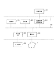
- FIG. 1 is a diagram showing an embodiment of a system for supporting a call.
- the system shown in FIG. 1 includes a call support device 1 (server), a customer terminal 2 (first terminal), and an operator terminal 3 (second terminal).
- the call support device 1 and the customer terminal 2 are such as the Internet. It is connected to a network 4 such as a public line or a dedicated line.
- the call support device 1 and the operator terminal 3 are connected via a network in a call center. Further, the call support device 1 provided separately from the call center and the operator terminal 3 in the call center may be connected to the network 4, for example.
- the customer terminal 2 is, for example, a telephone used by a customer, an Internet Protocol (IP) telephone, a soft phone, or the like.
- IP Internet Protocol
- FIG. 2 is a diagram illustrating an example of hardware of the call support device.
- the call support device 1 includes a control unit 201, a storage unit 202, a recording medium reading device 203, an input / output interface 204 (input / output I / F), a communication interface 205 (communication I / F), and the like. Each of the above components is connected by a bus 206.
- the call support device 1 can be realized by using a server or the like.
- the call support device 1 includes a control unit 201, a storage unit 202, and the like.
- the control unit 201 includes a connection unit 301, an audio recording unit 302, an analysis unit 303, an instruction unit 304, which will be described later.
- the control unit 201 may use a multi-core Central / Processing / Unit (CPU), a multi-core CPU or a programmable device (Field / Programmable / Gate / Array (FPGA), Programmable / Logic Device (PLD), etc.). That is, since it is required to promptly give an appropriate instruction to the operator, the control unit 201 is required to have a configuration in which the processing units operate in parallel and the calculation results of the processing units are used in cooperation. It is done.
- CPU Central / Processing / Unit
- FPGA Field / Programmable / Gate / Array
- PLD Programmable / Logic Device
- the storage unit 202 stores operator information 305, voice information 306, utterance date information 307, correspondence information 308, and the like, which will be described later.
- the storage unit 202 may be a memory such as a Read Only Memory (ROM) or a Random Access Memory (RAM), a hard disk, or the like.
- the storage unit 202 may record data such as parameter values and variable values, or may be used as a work area at the time of execution.
- the operator information 305, voice information 306, utterance date / time information 307, correspondence information 308, and the like may be stored in a database other than a table, or may be recorded in a database as hardware.
- the recording medium reading device 203 controls reading / writing of data with respect to the recording medium 207 according to the control of the control unit 201. Then, the data written under the control of the recording medium reader 203 is recorded on the recording medium 207, or the data recorded on the recording medium 207 is read.
- the removable recording medium 207 includes a computer-readable non-transitory recording medium such as a magnetic recording device, an optical disk, a magneto-optical recording medium, and a semiconductor memory.
- the magnetic recording device includes a hard disk device (HDD).
- Optical discs include Digital Versatile Disc (DVD), DVD-RAM, Compact Disc Read Read Only Memory (CD-ROM), CD-R (Recordable) / RW (ReWritable), and the like.
- Magneto-optical recording media include Magneto-Optical disk (MO). Note that the storage unit 202 is also included in a non-transitory recording medium.
- An input / output unit 208 is connected to the input / output interface 204, receives information input by the user, and transmits the information to the control unit 201 via the bus 206. Further, operation information and the like are displayed on the display screen in accordance with a command from the control unit 201.
- Examples of the input device of the input / output unit 208 include a keyboard, a pointing device (such as a mouse), and a touch panel.
- the display which is an output part of the input / output part 208 can consider a liquid crystal display etc., for example.
- the output unit may be an output device such as a CathodeathRay Tube (CRT) display or a printer.
- CTR CathodeathRay Tube
- the communication interface 205 is an interface for performing Local Area Network (LAN) connection, Internet connection, and wireless connection between the customer terminal 2 and the operator terminal 3.
- the communication interface 205 is an interface for performing LAN connection, Internet connection, or wireless connection with another computer as necessary. It is also connected to other devices and controls data input / output from external devices.
- Various processing functions to be described later are realized by using a computer having such a hardware configuration.
- a program describing the processing contents of the functions that the system should have is provided.
- the program describing the processing contents can be recorded in a computer-readable recording medium 207.
- a recording medium 207 such as a DVD or CD-ROM in which the program is recorded is sold. It is also possible to record the program in a storage device of the server computer and transfer the program from the server computer to another computer via a network.
- the computer that executes the program records, for example, the program recorded in the recording medium 207 or the program transferred from the server computer in its own storage unit 202. Then, the computer reads the program from its own storage unit 202 and executes processing according to the program. Note that the computer can also read the program directly from the recording medium 207 and execute processing according to the program. Further, each time the program is transferred from the server computer, the computer can sequentially execute processing according to the received program.
- FIG. 3 is a diagram illustrating an example of functions of the control unit and the storage unit.
- the control unit 201 in FIG. 3 includes a connection unit 301, an audio recording unit 302, an analysis unit 303, an instruction unit 304, and the like.
- connection unit 301 when the connection unit 301 receives a call from the customer terminal 2, the connection unit 301 searches operator information 305 described later and extracts an operator who is not in a call. For example, an operator who is not talking is extracted by referring to an identifier indicating whether the operator is talking or not talking.
- the connection unit 301 connects the extracted operator terminal 3 and the customer terminal 2 that has received the call so that a call can be made. Thereafter, the connection unit 301 instructs the voice recording unit 302 to notify the voice recording unit 302 of the recording start of the call.
- the connection unit 301 ends the call and records an identifier indicating that the operator is not busy in the operator information 305.
- connection unit 301 receives a hold notification to be put on hold transmitted from the control unit 401 of the operator terminal 3, thereby sending a hold message to the customer terminal 2 instead of the voice information transmitted from the operator terminal 3. To send. At the same time, the connection unit 301 transmits, for example, a hold notification for setting a hold state to the voice recording unit 302 and the analysis unit 303.
- connection unit 301 receives the hold notification indicating the hold release transmitted from the control unit 401 of the operator terminal 3, so that the customer terminal 2 can replace the hold message that has been transmitted so far with the operator terminal. Audio information from 3 is transmitted.
- connection unit 301 transmits a hold notification indicating hold release, for example, to the voice recording unit 302 and the analysis unit 303.
- the voice recording unit 302 When receiving the recording start notification instruction from the connection unit 301, the voice recording unit 302 records the customer's voice and the operator's voice in the voice information 306 described later in association with the date and time or the elapsed time from the start of the call. Note that only the customer's voice may be recorded in the voice information 306.
- the analysis unit 303 detects the communication hold state started by the hold notification transmitted by the operator terminal 3, and analyzes the feature of the customer's voice information in the hold state.
- the analysis unit 303 stores the customer voice transmitted from the customer terminal 2 in the storage unit 202.
- the customer's voice corresponding to the period of the hold state is acquired via the connection unit 301 and sent from the operator terminal 3 used by the operator who calls the customer to put the call with the customer terminal 2 on hold. Analyzing the characteristics of Then, the operator terminal 3 is notified of the operator's response to the customer according to the analysis result.
- the analysis unit 303 analyzes the customer's voice characteristics, and the average value p2 of the customer's voice level in the period corresponding to the hold state is larger than the average value p1 of the voice level corresponding to the period before the hold state. It is determined whether it is a value. When the average value p2 is large, the instruction unit 304 is notified that there is dissatisfaction with the response to the operator.
- the analysis unit 303 analyzes the characteristics of the customer's voice, and when the average value p2 is determined to be larger than the average value p1 after a certain period of time has elapsed since the date and time of transition to the hold state, the hold is prolonged.
- the instruction unit 304 is notified that there is dissatisfaction.
- the instruction unit 304 acquires message information (determination information) corresponding to the customer's psychological state obtained by the analysis unit 303 from the correspondence information 308 and outputs it to the operator terminal 3. For example, the instruction unit 304 outputs determination information regarding the customer's speaker based on the feature of the customer's voice information to the operator terminal 3.
- the determination information is information relating to an action that the operator should take on the customer.
- the operator information 305 stores operator information 305, voice information 306, utterance date information 307, correspondence information 308, and the like.
- the operator information 305, voice information 306, utterance date / time information 307, and correspondence information 308 will be described later.
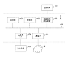
- FIG. 4 is a diagram illustrating an example of hardware of the operator terminal.
- the operator terminal 3 may be a personal computer (PC).
- the operator terminal 3 includes a control unit 401, a storage unit 402, a recording medium reading device 403, an input / output interface 404 (input / output I / F), a communication interface 405 (communication I / F), and the like. Further, each of the above components is connected by a bus 406.
- the control unit 401 may use a central processing unit (CPU) or a programmable device (such as a field programmable gate array (FPGA) or a programmable logic device (PLD)).
- the control unit 401 controls each unit of the operator terminal 3.
- the storage unit 402 may be a memory such as a Read Only Memory (ROM) or a Random Access Memory (RAM), a hard disk, or the like.
- the storage unit 402 may record data such as parameter values and variable values, or may be used as a work area at the time of execution.
- the recording medium reading device 403 controls reading / writing of data with respect to the recording medium 407 according to the control of the control unit 401. Then, the data written by the control of the recording medium reading device 403 is recorded on the recording medium 407, or the data recorded on the recording medium 407 is read.
- the detachable recording medium 407 includes a computer-readable non-transitory recording medium such as a magnetic recording device, an optical disk, a magneto-optical recording medium, and a semiconductor memory.
- the magnetic recording device includes a hard disk device (HDD).
- Optical discs include Digital Versatile Disc (DVD), DVD-RAM, Compact Disc Read Read Only Memory (CD-ROM), CD-R (Recordable) / RW (ReWritable), and the like.
- Magneto-optical recording media include Magneto-Optical disk (MO). Note that the storage unit 402 is also included in a non-transitory recording medium.
- An input / output unit 408 is connected to the input / output interface 404, receives information input by the user, and transmits the information to the control unit 401 via the bus 406. Further, operation information and the like are displayed on the display screen in accordance with a command from the control unit 401.
- Examples of the input device of the input / output unit 408 include a keyboard, a pointing device (such as a mouse), and a touch panel.
- the display which is an output part of the input / output part 408 can consider a liquid crystal display etc., for example.
- the output unit may be an output device such as a CathodeathRay Tube (CRT) display or a printer.
- CTR CathodeathRay Tube
- FIG. 5 is a diagram showing an embodiment of a device connected to an operator terminal.
- the input / output unit 408 connected to the operator terminal 3 illustrated in FIG. 5 includes a hold input unit 501, a voice input unit 502, and a voice output unit 503 illustrated in FIG.
- the hold input unit 501 notifies the call support device 1 of the start and release of the hold state. For example, when an operator needs time to prepare an answer when answering a customer's question, the on-hold notification of the start and release of the on-hold status is made while the customer is waiting. When streaming from the terminal 2, the call support apparatus 1 is notified of the start of the hold state. Further, when resuming the call, the call support apparatus 1 is notified of the cancellation of the hold state.
- the voice input unit 502 acquires the voice uttered by the operator and inputs it to the operator terminal 3. For example, a microphone.
- the voice output unit 503 outputs the customer's voice sent from the customer terminal 2. For example, headphones and speakers. Note that the audio input unit 502 and the audio output unit 503 may be headsets.
- the communication interface 405 is an interface for performing Local Area Network (LAN) connection, Internet connection, and wireless connection between the call support apparatus 1 and the customer terminal 2.
- the communication interface 405 is an interface for performing LAN connection, Internet connection, or wireless connection with another computer as necessary. It is also connected to other devices and controls data input / output from external devices.
- FIG. 6 is a flowchart showing an embodiment of the operation of the connection unit.
- the connection unit 301 receives a call transmitted from the customer terminal 2.
- the operator information 305 is searched for and detected whether there is an operator whose connection unit 301 is not in a call.
- the operator information is information indicating whether the operator terminal 3 used by the operator is connected to the customer terminal 2 and is talking or not talking.
- FIG. 7 is a diagram showing an embodiment of a data structure of operator information and voice information.
- the operator information 305 illustrated in FIG. 7 includes “operator ID” and “call status”.
- an identifier for identifying the operator terminal 3 currently used by the operator is recorded.
- “OP11111”, “OP22222”, “OP33333”,... are recorded as identifiers of operator terminals.
- the “call status” an identifier indicating whether the operator terminal 3 is currently connected to the customer terminal 2 and is talking or not is recorded. In this example, “1” indicating that the call is in progress and “0” indicating that the call is idle and not in use are recorded in association with the identifier of the operator terminal.
- step S604 If the connection unit 301 cannot detect the empty operator terminal 3, the process proceeds to step S603 (No).
- step S603 the connection unit 301 waits for connection with the customer terminal 2 that has received the call until it detects an empty operator terminal 3 in the operator information.
- the waiting time from when the call is received until connection is established and the voice of the customer may be recorded in the voice information 306. That is, even during this waiting time, data such as music and voice guidance is transmitted to the customer terminal 2 and is considered to be the same as the hold state instructed by the operator during the call. Therefore, since the customer thinks that his / her conversation is not transmitted to the operator, it is assumed that the customer expresses his / her real feelings such as dissatisfaction in a simple manner such as self-speaking, tongue-to-speech, and sigh. Note that the customer voice acquired in this state may be used as data for measuring the customer's psychological state after the operator terminal 3 determines the voice.
- step S604 the connection unit 301 connects the customer terminal 2 and the operator terminal 3 that are not in a call.
- the operator information 305 in FIG. 7 the operator corresponding to the identifier “OP33333” of the operator terminal is in an empty state, so that the customer terminal 2 that has received the call is connected.
- step S605 the connection unit 301 changes the state of the operator in the operator information to an identifier indicating that a call is in progress.
- the operator information 305 of FIG. 7 when the operator terminal 3 and the customer terminal 2 are connected, the identifier “0” indicating that the operator terminal 3 is free is changed to the identifier “1” indicating that a call is in progress.
- step S606 the connection unit 301 notifies the voice recording unit 302 by including information indicating the recording start of the call in the recording notification.
- the voice recording unit 302 records the voice of the operator who receives the recording notification indicating the start of recording and the voice of the customer.
- step S607 the connection unit 301 detects whether or not the call between the customer terminal 2 and the operator terminal 3 has ended. If it is detected that the call has ended, the process proceeds to step S608 (Yes), and the call continues. If yes, the process proceeds to step S607 (No).
- the connection unit 301 When it is detected that the call between the customer terminal 2 and the operator terminal 3 has ended, the connection unit 301 changes the call state of the operator terminal 3 in the operator information to an identifier indicating that the current call is empty in step S608. In the operator information 305 of FIG. 7, the identifier “1” indicating that the operator terminal 3 is busy is changed from the identifier “0” indicating that the operator terminal 3 is idle. In step S ⁇ b> 608, the connection unit 301 transmits a recording notification including information indicating that the call has ended to the voice recording unit 302.
- FIG. 8 is a flowchart showing an embodiment of the operation of the audio recording unit.
- step S ⁇ b> 801 when the voice recording unit 302 receives the recording start notification transmitted from the connection unit 301, the voice file for recording the customer voice and the operator voice is opened.
- the audio file for example, audio data recorded in a wave format format, an MP3 format format, or the like is recorded.
- the voice recording unit 302 records in the storage unit 202 that the customer and the operator who are currently talking are not speaking yet. For example, a customer utterance storage area and an operator utterance storage area are secured in the storage unit 202 as temporary, and when there is no utterance, “unspoken” indicating that the utterance is not yet stored is stored, and the customer and the operator are uttering. Sometimes it is assumed that the user is speaking and “speaking” is stored. Here, since it is shortly after connection, it is assumed that there is no utterance between the customer and the operator, and “unspoken” is stored in the customer utterance storage area and the operator utterance storage area. The determination as to whether or not an utterance has been made will be described later.
- step S803 it is determined whether or not the voice recording unit 302 is in a call. If the call is in progress, the process proceeds to step S804 (Yes), and if the call is ended, the process proceeds to step S808 (No). . For example, when a recording notification including information indicating that the call has ended is acquired from the connection unit 301, the process proceeds to step S808.
- step S804 the voice recording unit 302 acquires the customer's voice data and the operator's voice data at a predetermined cycle via the connection unit 301, and writes them into the voice file. For example, it is conceivable to write voice data and operator voice data to a voice file every 20 milliseconds. However, the writing of audio data is not limited to 20 milliseconds.
- step S805 the voice recording unit 302 transfers the customer's voice data to the analysis unit 303 at a predetermined cycle. For example, it is conceivable to transfer customer voice data to the analysis unit 303 every 20 milliseconds. However, the writing of the customer's voice data is not limited to 20 milliseconds.
- step S806 the voice recording unit 302 performs customer utterance extraction processing for extracting customer utterances
- step S807 the voice recording unit 302 performs operator utterance extraction processing for extracting operator utterances.
- the customer utterance extraction process and the operator utterance extraction process will be described later.
- step S808 the voice recording unit 302 closes the voice file, and in step S809, the voice recording unit 302 stores the voice file in the voice information.
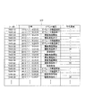
- the voice information 306 shown in FIG. 7 includes “call ID”, “voice file name”, “left channel speaker”, and “right channel speaker”.
- the “call ID” is an identifier attached to a call made between the customer terminal 2 and the operator terminal 3. In this example, “7840128”, “74040129”, “78440130”, “78440131”,... Are recorded as identifiers for identifying calls.
- a name indicating the voice file created by the voice recording unit 302 is recorded in association with the “call ID”.
- the recording location of the audio file is recorded in association with the audio data.
- “10080110232000.wav”, “10090116342010.wav”, “100903317321009.wav”, “10090332343000.wav”,... are recorded as names of audio files.
- “left channel speaker” and “right channel speaker” information indicating a channel in which a customer or an operator is recorded is recorded. In this example, “operator” indicating that the speech is from the operator is recorded on the left channel, and “customer” indicating that the speech is from the customer is recorded on the right channel.
- FIG. 9 is a diagram illustrating an example of the operation of the operator utterance extraction process.
- FIG. 10 is a diagram illustrating an example of the operation of the operator utterance extraction process.
- the maximum volume value V1 is obtained by using the operator's voice data for the period acquired for each predetermined period by the voice recording unit 302.
- the operator's voice data for 20 milliseconds is acquired every 20 milliseconds, and the data indicating the volume included in the voice data for 20 milliseconds is analyzed to obtain the maximum volume value V1.
- the period is not limited to 20 milliseconds.
- step S902 the audio recording unit 302 compares the maximum volume value V1 with a predetermined volume value V0 for each determined period, and determines whether V1> V0. If V1> V0, the process proceeds to step S903 (Yes), and if V1 ⁇ V0, the process proceeds to step S906.
- the silence value V0 is a volume that is considered to be silence. As the silence value V0, for example, noise during no call may be measured, and the average of the measured values may be set to the silence value V0.
- step S903 the voice recording unit 302 refers to the operator utterance storage area to determine whether or not it is an utterance. If it is not yet uttered, the process proceeds to step S904 (Yes). If not, the operator utterance extraction process is terminated, and the process proceeds to the next customer utterance extraction process.
- step S904 the voice recording unit 302 records the current date and time and information indicating that the operator has started speaking in the date and time information. For example, it may be recorded as the utterance date information 307 in FIG.
- FIG. 11 is a diagram showing an example of the data structure of the utterance date information.
- the utterance date / time information 307 of FIG. 11 includes “call ID”, “date / time”, “event type”, and “average volume in utterance”.
- the “call ID” is an identifier attached to a call made between the customer terminal 2 and the operator terminal 3.
- “7840128” ... Is recorded as an identifier for identifying a call.
- “Date and time” the current date and time when the operator starts speaking is recorded.
- Event type information indicating the type of event such as the start and end of the utterance of the operator or customer is recorded in association with the “date and time”.
- “operator utterance start”, “operator utterance end”, “customer utterance start”, “customer utterance end”, “hold start”, and “hold release” are recorded as information for classifying the event.
- the information indicating that the operator has started speaking is “operator speaking start”.
- the “average volume in utterance” records the average volume during the period when the customer uttered. A method for obtaining the average volume value in the utterance will be described later.
- the average utterance volume value V3 “31” “32” “12” “58” “34” is recorded in association with the period during which the customer uttered as the average utterance volume.
- the average volume in the utterance may be indicated by, for example, gain (dB), and is not limited as long as the volume can be shown.
- step S905 the voice recording unit 302 sets the operator utterance state to “speaking”.
- the “unspoken” in the operator utterance storage area is changed to “speaking”.
- step S906 the voice recording unit 302 refers to the operator utterance storage area to determine whether the utterance is in progress. If the utterance is in progress, the process proceeds to step S907 (Yes). If not, the operator utterance extraction process ends, and the process proceeds to the next customer utterance extraction process.
- the voice recording unit 302 records the current date and time and information indicating that the operator has finished speaking in the date and time information. For example, it may be recorded as the utterance date information 307 in FIG. Information indicating that the operator has finished speaking is “operator utterance finished”.
- step S908 the voice recording unit 302 sets the operator utterance state to “not uttered”. “Speaking” in the operator utterance storage area is changed to “unspoken”.
- FIG. 10 is a diagram illustrating an example of the operation of the customer utterance extraction process.
- the maximum sound volume value V2 is obtained using the customer's voice data for the period acquired for each predetermined period by the voice recording unit 302.
- the customer's voice data for 20 milliseconds is acquired every 20 milliseconds, and the data indicating the volume included in the voice data for 20 milliseconds is analyzed to obtain the maximum volume value V2.
- the period is not limited to 20 milliseconds.
- step S1002 the audio recording unit 302 compares the maximum volume value V2 with a predetermined volume value V0 for each determined period, and determines whether V2> V0. If V2> V0, the process proceeds to step S1003, and if V2 ⁇ V0, the process proceeds to step S1008.
- the silence value V0 is a volume that is considered to be silence. Further, the silence value V0 may be measured by measuring noise during no-call and the average of the measured values may be set to the silence value V0.
- step S1003 the voice recording unit 302 refers to the customer utterance storage area and determines whether or not the utterance is not yet made. If it is not yet uttered, the process proceeds to step S1004 (Yes). If not, the customer utterance extraction process is terminated, and the process proceeds to step S803 (No) in FIG.
- the voice recording unit 302 records the current date and time and information indicating that the customer has started speaking in the date and time information. For example, it may be recorded as the utterance date information 307 in FIG.
- the information indicating that the customer has started utterance is “customer utterance start”.
- step S1005 the voice recording unit 302 changes the volume total value V2S to the maximum volume value V2. That is, the maximum volume value V2 is substituted to initialize the volume total value V2S when the previous state is unspeaked.
- step S1006 the voice recording unit 302 sets the customer utterance state to “speaking”. “Unspeaked” in the customer utterance storage area is changed to “speaking”.
- step S1007 the audio recording unit 302 changes the total volume value V2S to V2S + V2. That is, when the previous state is speaking, the maximum volume value V2 acquired in this cycle is added to the previous volume total value V2S, and the added value is set as the volume total value V2S.
- step S1008 the voice recording unit 302 refers to the customer utterance storage area to determine whether the utterance is in progress. If the utterance is in progress, the process proceeds to step S1009 (Yes). If the utterance is not in progress, the customer utterance extraction process is terminated, and the process proceeds to step S803 (No) in FIG.
- step S1009 the voice recording unit 302 records the current date and time and information indicating that the operator has finished speaking in the date and time information. For example, as shown in the utterance date / time information 307 in FIG. 11, it is conceivable to record in “date / time” and “event type”. The information indicating that the customer has finished speaking is “customer speech finished”.
- step S1010 the voice recording unit 302 calculates the average volume value V3 in the utterance.
- the average utterance volume value V3 is obtained by using the following formula: volume total value V2S / (customer utterance end date-customer utterance start date) ⁇ sampling number sample.
- the sampling number sample is the quantity of data obtained by sampling the customer's voice within a predetermined period. That is, the number of samplings in the cycle.
- step S1011 the voice recording unit 302 stores the utterance end date / time and the average utterance volume value V3 in the “average utterance volume” of the utterance date / time information 307.
- the average utterance volume value V3 “31” “32” “12” “58” “34” is stored in association with the customer utterance end date and time.
- step S1012 the voice recording unit 302 sets the customer utterance state to “not uttered”. “Speaking” in the customer utterance storage area is changed to “unspoken”. The operation of the analysis unit 303 will be described.
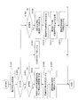
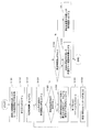
- FIG. 12 is a diagram illustrating an example of the operation of the analysis unit according to the first embodiment.
- the analysis unit 303 receives a hold notification indicating a hold start transmitted from the operator terminal 3, and detects that it is in a hold state.
- the hold notification of the hold start notifies the operator terminal 3 via the input / output interface 404 that the hold input unit 501 sets the hold state when the operator sets the hold state during a call.
- the control unit 401 When the notification is received, the control unit 401 generates a hold notification indicating the start of hold and transmits it to the connection unit 301.
- the connection unit 301 transmits the received hold notification to the analysis unit 303.
- the analysis unit 303 analyzes the hold notification and detects that the hold has started.
- the analysis unit 303 determines whether or not it is a pending start (indicating pending). If the pending start is detected, the process proceeds to step S1202 (Yes). If not, the pending start is detected. stand by.
- step S1202 the analysis unit 303 records the current date and time as the hold start date and time in the utterance date and time information. For example, in the case of the utterance date / time information 307 in FIG. 11, “2010/1/1 10:24:47 indicating 10:24:47 on January 1, 2010 as the hold start date / time in the call ID“ 78440128 ”. Is recorded. In addition, “hold start” is recorded in the related event type.
- step S1203 the analysis unit 303 obtains an average value p1 of the volume before suspension. The calculation process of the average speech volume value before holding will be described later.
- step S1204 the current date and time that is being held by the analysis unit 303 is set as the processing date and time pt1.
- step S1205 the analysis unit 303 determines whether or not a predetermined time has elapsed. If it has elapsed, the process proceeds to step S1206 (Yes). If not, the analysis unit 303 waits until the predetermined time elapses.
- step S1206 the analysis unit 303 obtains the utterance end date / time and the average volume value p2 in the utterance of the customer existing between the processing date / time pt1 and the current date / time.
- the utterance date / time information 307 shown in FIG. 11 in the utterance associated with “customer utterance end” from the processing date / time pt1 to the current date / time in the event type “hold start” to “hold end” period.
- the average volume value V3 is acquired.
- step S1207 if the analysis unit 303 cannot acquire the date and time when the customer utterance ends from the utterance date and time information, the process proceeds to step S1212 (Yes), and if it can be acquired, the process proceeds to step S1208 (No). That is, if it cannot be acquired, the process proceeds to step S1212 in order to acquire the date and time when the customer utterance ends.
- step S1208 the analysis unit 303 compares the average utterance volume p2 in utterance and the average utterance volume p1 before holding, and when p2> p1, the process proceeds to step S1209 (Yes), and when p2 ⁇ p1, step S1212 is performed. Move to (No). If p2> p1, it is estimated that the customer is dissatisfied because the customer is speaking in a louder voice than before the hold. When p2 ⁇ p1, it is estimated that the operator is not dissatisfied.
- step S1209 the analysis unit 303 determines whether or not the limit time has elapsed. If the limit time has not elapsed, the process proceeds to step S1210 (Yes). If the limit time has elapsed, step S1211 (No).
- Migrate to The limit time is a threshold value used for comparing the current time of the hold from the hold start date and time, and is recorded in the storage unit 202.
- the limit time is, for example, a time when dissatisfaction starts when a customer waits in a hold state, and is a value determined by past survey results. Therefore, it is in a state where there is no dissatisfaction before the time limit has elapsed, and if the time limit has passed, it is presumed that the customer is dissatisfied with waiting in the hold state.
- step S1210 the analysis unit 303 writes “1” in the emotion flag.
- “1” when “1” is written in the emotion flag, it indicates that there is dissatisfaction with the operator's response itself.
- step S1211 the analysis unit 303 writes “2” in the emotion flag.
- the emotion flag is “2”, it indicates that there is dissatisfaction with having waited for a long time due to the hold.
- the emotion flag is an area in which, for example, a storage area for the emotion flag is secured in the storage unit 202 as a temporary area, and a value corresponding to the customer's psychological state is written.
- the customer's psychological state is indicated by dissatisfaction levels “1” and “2”.
- step S ⁇ b> 1212 the cognitive analysis unit 303 receives the hold notification indicating the hold release transmitted from the operator terminal 3, and detects that the hold is released.
- the hold notification for releasing the hold notifies the operator terminal 3 through the input / output interface 404 that the hold is to be released from the hold input unit 501 when the operator releases the hold during a call.
- the control unit 401 When the notification is received, the control unit 401 generates a hold notification indicating the hold release and transmits it to the connection unit 301.
- the connection unit 301 transmits the received hold notification to the analysis unit 303.
- the analysis unit 303 analyzes the hold notification and detects that the hold is released.
- step S1213 Yes
- step S1204 No
- step S1213 the analysis unit 303 refers to the emotion flag and determines whether or not a value corresponding to the psychological state of the customer is stored in the emotion flag. If a value is stored in the emotion flag, the process proceeds to step S1214 (Yes). If stored in the emotion flag, the process ends and waits for the next hold start.
- step S1214 the analysis unit 303 notifies the instruction unit 304 of a correspondence instruction notification including information indicated by the emotion flag. Thereafter, the instruction unit 304 receives the correspondence instruction notification, selects message information (determination information) for supporting the operator corresponding to the information indicated by the emotion flag from the correspondence information 308, and connects the selected message information to the connection information.
- the data is transmitted to the operator terminal 3 via the unit 301.
- FIG. 13 is a diagram illustrating an example of an operation of calculating the average utterance volume before holding.
- the analysis unit 303 acquires the latest date / time or the call start date / time from the previous utterance release from the utterance date / time information and sets it to t1.
- the latest date and time of the previous hold release if the hold status is intermittent several times during a call, the hold release date of the latest hold status is acquired.
- the call start date and time is acquired.
- step S1302 the analysis unit 303 sets the volume product value Vp to 0, and in step S1303, the analysis unit 303 sets the utterance time product tp to 0 and substitutes an initial value.
- step S1304 the analysis unit 303 sets the date and time of customer utterance start after t1 to t2.
- the utterance date / time information 307 shown in FIG. 11 when the call start date / time is t1 and “2010/1/1 10:23:43”, “2010/1/1 10:23:59” “2010” / 1/1 10:24:03 "becomes t2.
- step S1305 the analysis unit 303 determines whether or not t2 can be acquired. If it can be acquired, the process proceeds to step S1306 (Yes). If not, the process proceeds to step S1309 (No). . If it can be obtained, the customer has not yet spoken.
- step S1306 the analysis unit 303 sets t3 as the earliest date and time of customer utterance end date and time after t2, and Vc1 as the average volume in the utterance corresponding to the date and time.
- the utterance date / time information 307 shown in FIG. 11 when t2 is “2010/1/1 10:23:59”, the earliest date and time at the end of the customer utterance after t2 is “2010/1 / Since 1 10:24:01 ”,“ 2010/1/1 10:24:01 ”is set as t3. Then, the average utterance volume “31” associated with “2010/1/1 10:24:01” is set as Vc1.
- step S1307 the analysis unit 303 adds (Vc1 ⁇ (t2-t3)) to the volume product value Vp.
- step S1308 the analysis unit 303 adds (t2-t3) to the speech time product value tp.
- step S1309 the analysis unit 303 determines whether or not the speech time product value tp is equal to or greater than 0. If it is equal to or greater than 0, the analysis unit 303 proceeds to step S1310 (Yes), and if smaller than 0, proceeds to step S1311 (No). To do.
- step S1310 the analysis unit 303 obtains the volume product value Vp ⁇ speech time product value tp and sets the volume average value p1 before holding.
- step S1311 the analysis unit 303 sets the pre-hold volume average value p1 as the silence value V0.
- a technique disclosed in Japanese Patent Application Laid-Open No. 2004-317822 may be used as a technique for performing emotion recognition by quantifying volume power change information using voice volume power information.
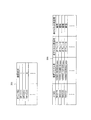
- FIG. 14 is a diagram illustrating a time chart of an example of the method for analyzing the voice characteristics of the customer according to the first embodiment.
- the average utterance volume value p1 before hold obtained in the flowchart shown in FIG. 13 is the average utterance volume value p1 (value between dotted lines) in the period before hold (t1—hold start) in the time chart shown in FIGS. Is shown.
- the time chart shown in A of FIG. 14 is a time chart when “1” is written in the emotion flag obtained in the flowchart shown in FIG. Since the average utterance volume value p2 in the utterance is larger than the average utterance volume value p1 before holding, it indicates that the customer is dissatisfied with the operator for the operator's response itself.
- 14B is a time chart when “2” is written in the emotion flag obtained in the flowchart shown in FIG. 12 in step S1211. Since the average utterance volume value p2 in the utterance is larger than the average utterance volume value p1 before holding after the limit time elapses, it indicates that there is dissatisfaction with waiting for a long time by holding.
- FIG. 15 is a diagram illustrating an example of a data structure of message contents and correspondence information.
- the correspondence information 308 in FIG. 15 includes “emotion flag” and “message information”.
- an identifier indicating the customer's psychological state stored in the emotion flag is recorded.
- “message information” a message for assisting the operator is recorded in association with the emotion flag.
- “mes_1”, “mes_2”, and “mes_3” corresponding to the messages 1501, 1502, and 1503 shown in FIG. 15 are recorded.
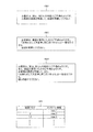
- a message 1501 is a message selected when “1” is recorded in the emotion flag. “1” in the emotion flag indicates that the operator is dissatisfied with the response itself, so “The customer is actually dissatisfied with your response.” And then resume the conversation. "
- the message 1502 is a message selected when “2” is recorded in the emotion flag. If the emotion flag is “2”, it indicates that you are dissatisfied with the long hold status, so “The customer seems to be dissatisfied because the hold has been prolonged.” “I ’m sorry to make you wait. Please say “No, then resume conversation”.
- Message 1503 is a message selected when both “1” and “2” are recorded in the emotion flag.
- the emotion flag indicates that there is dissatisfaction with the operator's response itself and that he / she waited for a long time due to the hold. “The customer is actually dissatisfied with your response. Also, it seems that you are dissatisfied with the prolonged suspension. Being aware of the customer ’s intent,“ I ’m sorry to make you wait. ” Please continue to speak. "And other messages.
- the first embodiment by acquiring the voice uttered by the customer in the on-hold state instructed by the operator during the call, analyzing the characteristics of the acquired voice, and measuring the psychological state of the customer based on the analysis result.
- the accuracy of measuring the customer's psychological state can be improved. That is, since the customer thinks that his / her conversation is not transmitted to the operator during the hold, it is assumed that the customer expresses the true feelings such as dissatisfaction in a simple manner such as a single word, a sigh, a sigh and the like.
- the customer's psychological state is measured by acquiring the customer's voice in the on-hold state that has not been used to measure the customer's psychological state in the past, and performing analysis processing described later on the characteristics of the acquired voice. Accuracy can be improved. Further, by improving the accuracy of measuring the customer's psychological state, the operator's instruction to the customer can be made appropriate according to the customer's psychological state.
- Embodiment 2 will be described.
- the storage unit 202 of the second embodiment stores a specific word / phrase indicating a specific psychological state or a specific word / phrase estimated to indicate a specific psychological state.
- the analysis unit 303 of the second embodiment refers to the storage unit 202 and determines whether or not a specific word / phrase is included in the customer's voice information in the hold state.
- the analysis unit 303 according to the second embodiment performs voice recognition processing on the voice in the period corresponding to the hold state. For example, the dissatisfied word recorded in the dissatisfied word information indicating that the customer is dissatisfied is It is determined whether or not it is included.
- a specific phrase indicating a specific psychological state or a specific phrase estimated to indicate a specific psychological state dissatisfied word information indicating that the customer is dissatisfied can be considered.
- the instruction unit 304 of the second embodiment outputs message information (determination information) related to the customer's psychological state to the operator terminal 3 based on the determination result of whether or not a specific word is included.
- message information determination information
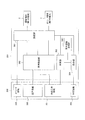
- FIG. 16 is a diagram illustrating an example of functions of the control unit and the storage unit according to the second embodiment.
- the control unit 201 in FIG. 16 includes a connection unit 301, a voice recording unit 302, an analysis unit 303, an instruction unit 304, a voice recognition processing unit 1601, and the like.
- the description of the connection unit 301, the voice recording unit 302, and the instruction unit 304 has been described in the first embodiment, and will be omitted.
- FIG. 17 is a diagram illustrating an example of the operation of the analysis unit according to the second embodiment.
- the analysis unit 303 receives a hold notification indicating a hold start transmitted from the operator terminal 3, and detects that it is in a hold state.
- the hold notification of the hold start notifies the operator terminal 3 via the input / output interface 404 that the hold input unit 501 sets the hold state when the operator sets the hold state during a call.
- the control unit 401 When the notification is received, the control unit 401 generates a hold notification indicating the start of hold and transmits it to the connection unit 301.
- the connection unit 301 transmits the received hold notification to the analysis unit 303.
- the analysis unit 303 analyzes the hold notification and detects that the hold has started.
- the analysis unit 303 determines whether or not it is a pending start (indicating pending). If the pending start is detected, the process proceeds to step S1202, and if not, the analysis unit 303 waits until the pending start is detected.
- step S1702 the analysis unit 303 records the current date and time as the hold start date and time in the utterance date and time information. For example, in the case of the utterance date / time information 307 in FIG. 11, “2010/1/1 10:24:47 indicating 10:24:47 on January 1, 2010 as the hold start date / time in the call ID“ 78440128 ”. Is recorded. In addition, “hold start” is recorded in the related event type.
- step S1703 the analysis unit 303 creates dissatisfaction word detection information as a storage area for recording dissatisfaction words detected by the speech recognition process.
- FIG. 18 shows dissatisfaction word detection information 1801.
- the dissatisfaction word detection information 1801 includes “detection date and time” and “detection keyword”.
- Detection date and time the date and time when the dissatisfaction word is detected is stored.
- “2010/1/1 10:24:55”, “2010/1/1 10:24:59”,... are stored as the date and time when the dissatisfaction word was detected.
- the detected dissatisfied word is recorded in association with the date and time when the dissatisfied word was detected.
- “disgusting”, “irritated”,... are stored as dissatisfied words.
- step S1704 the analysis unit 303 notifies the voice recognition processing unit 1601 of an instruction to start the voice recognition processing. This voice recognition process will be described later.
- step S1705 the analysis unit 303 sets the current date and time on hold as the processing date and time pt1.
- step S1706 the analysis unit 303 determines whether or not a predetermined time has elapsed. If it has elapsed, the process proceeds to step S1206 (Yes), and if not, the analysis unit 303 waits until the predetermined time elapses.
- step S1707 the analysis unit 303 acquires the detected dissatisfied words existing between the processing date and time pt1 and the current date and time from the dissatisfied word detection information.
- step S1708 the analysis unit 303 determines whether or not an unsatisfied word has been acquired from the unsatisfactory word detection information. If acquired, the process proceeds to step S1712 (Yes). If not, the process proceeds to step S1712. To do.
- step S1709 the analysis unit 303 determines whether or not the limit time has elapsed. If the limit time has not elapsed, the process proceeds to step S1210 (Yes). If the limit time has elapsed, step S1211 (No).
- Migrate to The limit time is a threshold value used for comparing the current time of the hold from the hold start date and time, and is recorded in the storage unit 202.
- the limit time is, for example, a time when dissatisfaction starts when a customer waits in a hold state, and is a value determined by past survey results. Therefore, it is in a state where there is no dissatisfaction before the time limit has elapsed, and if the time limit has passed, it is presumed that the customer is dissatisfied with waiting in the hold state.
- step S1710 the analysis unit 303 writes “1” in the emotion flag.
- “1” when “1” is written in the emotion flag, it indicates that there is dissatisfaction with the operator's response itself.
- step S1711 the analysis unit 303 writes “2” in the emotion flag.
- the emotion flag is “2”, it indicates that there is dissatisfaction with having waited for a long time due to the hold.
- the emotion flag is an area in which, for example, a storage area for the emotion flag is secured in the storage unit 202 as a temporary area, and a value corresponding to the customer's psychological state is written.
- the customer's psychological state is indicated by dissatisfaction levels “1” and “2”.
- the cognitive analysis unit 303 receives a hold notification transmitted from the operator terminal 3 and indicates that the hold has been released.
- the hold notification for releasing the hold notifies the operator terminal 3 through the input / output interface 404 that the hold is to be released from the hold input unit 501 when the operator releases the hold during a call.
- the control unit 401 When the notification is received, the control unit 401 generates a hold notification indicating the hold release and transmits it to the connection unit 301.
- the connection unit 301 transmits the received hold notification to the analysis unit 303.
- the analysis unit 303 analyzes the hold notification and detects that the hold is released.
- the analysis unit 303 determines whether or not the hold is released. If the hold is detected, the process proceeds to step S1713 (Yes), and if not, the process proceeds to step S1704 (No).
- step S1713 the analysis unit 303 notifies the voice recognition processing unit 1601 of an instruction to end the voice recognition processing.
- step S1714 the analysis unit 303 refers to the emotion flag to determine whether or not a value corresponding to the customer's psychological state is stored in the emotion flag. If a value is stored in the emotion flag, the process proceeds to step S1214 (Yes). If stored in the emotion flag, the process ends and waits for the next hold start.
- step S1715 the analysis unit 303 notifies the instruction unit 304 of a correspondence instruction notification including information indicated by the emotion flag.
- the instruction unit 304 receives the correspondence instruction notification, selects message information (determination information) for supporting the operator corresponding to the information indicated by the emotion flag from the correspondence information 308, and selects the selected message information (determination information). ) To the operator terminal 3 via the connection unit 301.
- FIG. 19 is a diagram illustrating an example of an operation of voice recognition processing.
- the voice recognition processing unit 1601 receives a voice recognition start instruction from the analysis unit 303.
- the speech recognition processing unit 1601 reads dissatisfied keyword information 1802.
- the dissatisfied keyword information 1802 is recorded in the storage unit 202, for example, a table in which dissatisfied words are registered.
- the dissatisfied word information 1802 stores “unsuccessful”, “be quick”, “be irritated”, “be sure”, etc. as dissatisfied words.
- the speech recognition processing unit 1601 performs speech recognition processing.
- the speech recognition process is a process for detecting whether a specified keyword (unsatisfied keyword information 1802) is included in the speech waveform.
- the speech recognition processing unit 1601 specifies the characteristics of the speech waveform when the dissatisfied words registered in the dissatisfied keyword information 1802 are pronounced. This specifying process may be performed, for example, before the voice recognition process of the customer's utterance is actually performed and stored in the voice recognition processing storage unit.
- the speech recognition processing unit 1601 detects whether or not a dissatisfaction word is included by comparing the speech waveform characteristics of each dissatisfaction word stored in the storage unit with the speech waveform of the actual customer utterance.
- speech recognition processing disclosed in JP-A-2005-142897, JP-A-2008-53826, and the like can be used.
- step S1904 it is determined whether or not the speech recognition processing unit 1601 has detected an unsatisfactory word. If detected, the process proceeds to step S1905, and if not detected, the process proceeds to step S1906.
- step S 1905 the dissatisfied word detected by the speech recognition processing unit 1601 is recorded in the dissatisfied word detection information 1801 in association with the date and time at which it was detected.
- step S1906 it is determined whether or not the voice recognition processing unit 1601 has received an instruction to end the voice recognition processing from the analysis unit 303. If received, the voice recognition processing is stopped, and if not received, step S1903 is received. Migrate to That is, the speech recognition process is stopped when the hold state is released. The voice recognition processing unit 1601 calculates dissatisfaction word detection information 1801.
- FIG. 20 is a diagram illustrating a time chart of an example of the method for analyzing the voice characteristics of the customer according to the second embodiment.
- the time chart shown in A of FIG. 20 is a time chart when “1” is written in the emotion flag obtained in the flowchart shown in FIG. Since the dissatisfaction word “Mukatsu” is detected in the voice of the customer on hold, it indicates that the customer is dissatisfied with the operator's response itself.
- the time chart shown in B of FIG. 17 is a time chart when “2” is written in the emotion flag obtained in the flowchart shown in FIG. Since the dissatisfaction word “Mukatsu” is detected in the voice of the customer who is on hold after the limit time has elapsed, this indicates that there is dissatisfaction with having waited for a long time due to the hold.
- the instruction unit 304 receives the correspondence instruction notification, selects message information for supporting the operator corresponding to the information indicated by the emotion flag from the correspondence information 308, and selects the selected message information via the connection unit 301. Transmit to terminal 3.
- a message for supporting the operator shown in FIG. 15 is displayed on the display which is the output unit of the input / output unit 408 connected to the operator terminal 3.
- the second embodiment it is possible to acquire the voice uttered by the customer in the hold state designated by the operator during the call, analyze the characteristics of the acquired voice, and measure the customer's psychological state based on the analysis result. , The accuracy of measuring the customer's psychological state can be improved. That is, since the customer thinks that his / her conversation is not transmitted to the operator during the hold, it is assumed that the customer expresses the true feelings such as dissatisfaction in a simple manner such as a single word, a sigh, a sigh and the like.
- the customer's psychological state is measured by acquiring the customer's voice in the on-hold state that has not been used to measure the customer's psychological state in the past, and performing analysis processing described later on the characteristics of the acquired voice. Accuracy can be improved. Further, by improving the accuracy of measuring the customer's psychological state, the operator's instruction to the customer can be made appropriate according to the customer's psychological state.
- the present invention is not limited to the above-described embodiment, and various improvements and changes can be made without departing from the gist of the present invention.
- Each embodiment may be combined with each other as long as there is no contradiction in processing.
Landscapes
- Engineering & Computer Science (AREA)
- Signal Processing (AREA)
- Health & Medical Sciences (AREA)
- Computational Linguistics (AREA)
- Audiology, Speech & Language Pathology (AREA)
- Human Computer Interaction (AREA)
- Physics & Mathematics (AREA)
- Acoustics & Sound (AREA)
- Multimedia (AREA)
- Marketing (AREA)
- Business, Economics & Management (AREA)
- General Health & Medical Sciences (AREA)
- Otolaryngology (AREA)
- Data Mining & Analysis (AREA)
- Quality & Reliability (AREA)
- Telephonic Communication Services (AREA)
Abstract
Description
指示手段は、上記第1の発話者の音声情報の特徴に基づいた該第1の発話者に関する判定情報を上記第2の端末に出力する。
実施形態1は、オペレータが通話中に指示した保留状態における顧客の発した音声を取得し、取得した音声の特徴を解析し、その解析結果に基づいて顧客の心理状態を測定することで、顧客の心理状態を測定する精度を向上させることができる。すなわち、保留中において顧客は、自身の会話がオペレータに伝わっていないと思っているため、顧客は不満などの本当の感情を独り言、舌打ち、ため息などなどの形で素直に表現すると想定される。そのため、従来顧客の心理状態を測定するために利用されなかった保留状態における顧客の発した音声を取得し、取得した音声の特徴を後述する解析処理をすることで、顧客の心理状態を測定する精度を向上させることができる。また、顧客の心理状態を測定する精度が向上することにより、オペレータを支援する際の顧客への指示内容を、顧客の心理状態に応じた適切なものにできる。
図2は、通話支援装置のハードウェアの一実施例を示す図である。通話支援装置1は、制御部201、記憶部202、記録媒体読取装置203、入出力インタフェース204(入出力I/F)、通信インタフェース205(通信I/F)などを備えている。また、上記各構成部はバス206によってそれぞれ接続されている。
図3は、制御部と記憶部の機能の一実施例を示す図である。図3の制御部201は、接続部301、音声記録部302、解析部303、指示部304などを有している。
図4は、オペレータ端末のハードウェアの一実施例を示す図である。オペレータ端末3は、Personal Computer(PC)などを用いることが考えられる。オペレータ端末3は、制御部401、記憶部402、記録媒体読取装置403、入出力インタフェース404(入出力I/F)、通信インタフェース405(通信I/F)などを備えている。また、上記各構成部はバス406によってそれぞれ接続されている。制御部401は、Central Processing Unit(CPU)やプログラマブルなデバイス(Field Programmable Gate Array(FPGA)、Programmable Logic Device(PLD)など)を用いることが考えられる。制御部401は、オペレータ端末3の各部を制御する。
図6は、接続部の動作の一実施例を示すフロー図である。ステップS601では、接続部301が顧客端末2から送信された呼を受信する。
図8は、音声記録部の動作の一実施例を示すフロー図である。ステップS801では、音声記録部302が接続部301から送信された記録開始通知を受信すると、顧客の音声とオペレータの音声を記録する音声ファイルを開く。音声ファイルは、例えば、ウェーブフォーマット形式やエムピースリーフォーマット形式などで記録された音声データが記録されている。
「左チャネル発話者」「右チャネル発話者」には、顧客またはオペレータが記録されているチャネルを示す情報が記録されている。本例では、左チャネルにオペレータの発話であることを示す「オペレータ」が記録され、右チャネルに顧客の発話であることを示す「顧客」が記録されている。
図9は、オペレータ発話抽出処理の動作の一実施例を示す図である。図10は、オペレータ発話抽出処理の動作の一実施例を示す図である。
ステップS906では、音声記録部302がオペレータ発話記憶領域を参照して発話中であるか否かを判定する。発話中である場合にはステップS907(Yes)に移行し、そうでない場合にはオペレータ発話抽出処理を終了して、次の顧客発話抽出処理に移行する。
図10のステップS1001では、音声記録部302が決められた周期ごとに取得した周期分の顧客の音声データを用いて、最大音量値V2を求める。例えば、20ミリ秒周期ごとに20ミリ秒分の顧客の音声データを取得し、その20ミリ秒分の音声データに含まれる音量を示すデータを解析して、最大音量値V2を求める。ただし、周期は20ミリ秒に限定されるものではない。
ステップS1007では、音声記録部302が音量合計値V2SをV2S+V2に変更する。つまり、前の状態が発話中である場合、本周期において取得した最大音量値V2を前回の音量合計値V2Sに加算して、加算した値を音量合計値V2Sとする。
解析部303の動作について説明する。
ステップS1204では、解析部303が保留中の現在日時を処理日時pt1とする。
ステップS1304では、解析部303がt1以降の顧客発話開始の日時をt2とする。図11に示す発話日時情報307の例であれば、通話開始日時をt1として「2010/1/1 10:23:43」とした場合、「2010/1/1 10:23:59」「2010/1/1 10:24:03」がt2となる。
図14は、実施形態1の顧客の音声の特徴を解析する方法の一実施例のタイムチャートを示す図である。図13に示すフロー図で求めた保留前平均発話音量値p1は、図14のA、Bに示すタイムチャートの保留前期間(t1-保留開始)の平均発話音量値p1(点線間の値)を示している。図14のAに示すタイムチャートは、図12に示すフロー図で求めた感情フラグに「1」が書き込まれた場合のタイムチャートである。保留前平均発話音量値p1より発話内平均音量値p2が大きいため、オペレータの対応自体に対して顧客がオペレータに不満があることを示している。
指示部304は対応指示通知を受信して、感情フラグの示す情報に対応するオペレータを支援するためのメッセージ情報を対応情報308から選択して、選択したメッセージ情報を、接続部301を介してオペレータ端末3に送信する。図15は、メッセージの内容と対応情報のデータ構造の一実施例を示す図である。図15の対応情報308は、「感情フラグ」「メッセージ情報」有している。「感情フラグ」には、感情フラグに記憶されている顧客の心理状態を示す識別子が記録されている。本例では、不満度を示す「1」「2」「1,2」・・・・が記録されている。「メッセージ情報」には、オペレータを支援するメッセージが感情フラグに関連付けられて記録されている。本例では、図15に示すメッセージ1501、1502、1503に対応する「mes_1」「mes_2」「mes_3」がそれぞれ記録されている。
実施形態2の記憶部202には、特定の心理状態を示す特定の語句、あるいは、特定の心理状態を示すと推定される特定の語句を記憶する。
図17は、実施形態2の解析部の動作の一実施例を示す図である。ステップS1701では、解析部303がオペレータ端末3から送信される保留開始を示す保留通知を受信して、保留状態であることを検出する。保留開始の保留通知は、オペレータが通話中に保留状態にする際に、保留入力部501から保留状態にすることをオペレータ端末3に入出力インタフェース404を介して通知する。その通知を受信すると、制御部401は保留開始を示す保留通知を生成して接続部301に送信される。接続部301は受信した保留通知を、解析部303に送信する。解析部303は受信した保留通知を受信した後、保留通知を解析して保留開始であることを検出する。
ステップS1705では、解析部303が保留中の現在日時を処理日時pt1とする。
ステップS1708では、解析部303が不満語検出情報から不満語を取得したか否かを判定し、取得した場合にはステップS1712(Yes)に移行し、取得していない場合にはステップS1712に移行する。
ステップS1714では、解析部303が感情フラグを参照して、感情フラグに顧客の心理状態に応じた値が記憶されているか否かを判定する。感情フラグに値が記憶されている場合はステップS1214(Yes)に移行し、記憶されている場合は本処理を終了して、次の保留開始を待つ。
ステップS1902では、音声認識処理部1601が不満語キーワード情報1802を読み込む。不満語キーワード情報1802は、例えば、不満語を登録したテーブルなどで、記憶部202に記録されている。不満語キーワード情報1802は、不満語として「むかつく」「早くしろよ」「イライラする」「しっかりしろよ」・・・・などを記憶している。
ステップS1906では、音声認識処理部1601が解析部303から音声認識処理を終了する指示を受信したか否かを判定し、受信したときは音声認識処理を停止し、受信していないときはステップS1903に移行する。すなわち、保留状態が解除された場合に音声認識処理を停止する。音声認識処理部1601は、不満語検出情報1801を求める。
図20は、実施形態2の顧客の音声の特徴を解析する方法の一実施例のタイムチャートを示す図である。図20のAに示すタイムチャートは、図17に示すフロー図で求めた感情フラグに「1」を書き込まれた場合のタイムチャートである。保留中の顧客の音声に不満語である「むかつく」を検出しているので、オペレータの対応自体に対して顧客が不満であることを示している。
指示部304は対応指示通知を受信して、感情フラグの示す情報に対応するオペレータを支援するためのメッセージ情報を対応情報308から選択して、選択したメッセージ情報を、接続部301を介してオペレータ端末3に送信する。通話支援装置1から送信されたメッセージ情報を受信すると、オペレータ端末3に接続されている入出力部408の出力部であるディスプレイに、図15に示すオペレータを支援するメッセージが表示される。
2 顧客端末
3 オペレータ端末
4 ネットワーク
201 制御部
202 記憶部
203 記録媒体読取装置
204 入出力インタフェース
205 通信インタフェース
206 バス
207 記録媒体
208 入出力部
301 接続部
302 音声記録部
303 解析部
304 指示部
305 オペレータ情報
306 音声情報
307 発話日時情報
308 対応情報
401 制御部
402 記憶部
403 記録媒体読取装置
404 入出力インタフェース
405 通信インタフェース
406 バス
407 記録媒体
408 入出力部
501 保留入力部
502 音声入力部
503 音声出力部
1601 音声認識処理部
Claims (12)
- 第1の発話者が用いる第1の端末と第2の発話者が用いる第2の端末間で行なわれる通信において、第2の発話者を支援する通話支援装置であって、
前記第2の端末によって送信された保留通知によって開始された該通信の保留状態を検知し、該保留状態における前記第1の発話者の音声情報の特徴を解析する解析手段と、
前記第1の発話者の音声情報の特徴に基づいた該第1の発話者に関する判定情報を前記第2の端末に出力する指示手段
を備えることを特徴とする通話支援装置。 - さらに、前記第1の端末と前記第2の端末間で行なわれる通信における前記第1の発話者の音声情報を記憶する記憶手段を備え、
前記解析手段は、
前記記憶手段を参照し、保留状態における前記第1の発話者の音声情報の音声レベルの第1の平均値と、該保留状態以前の該第1の発話者の音声情報の音声レベルの第2の平均値を比較し、
前記指示手段は、
前記第1の平均値と前記第2の平均値との比較結果に基づき、前記第1の発話者の心理状態に関連する前記判定情報を、前記第2の端末に出力する、
ことを特徴とする請求項1に記載の通話支援装置。 - 前記解析手段は、
保留状態に移行した時点から一定期間経過後に、前記第1の平均値と前記第2の平均値とを比較する、
ことを特徴とする請求項2に記載の通話支援装置。 - さらに、特定の心理状態を示す特定の語句、あるいは、特定の心理状態を示すと推定される特定の語句を記憶した記憶手段を備え、
前記解析手段は、
前記記憶手段を参照し、保留状態における前記第1の発話者の音声情報に前記特定の語句が含まれるか否かを判断し、
前記指示手段は、
前記特定の語句が含まれるか否かの判断結果に基づき、前記第1の発話者の心理状態に関連する前記判定情報を、前記第2の端末に出力する、
ことを特徴とする請求項1に記載の通話支援装置。 - 前記指示手段は、
保留状態に移行した時点から一定期間経過後に、前記特定の語句が前記第1の発話者の音声情報に含まれていると判定されたとき、前記保留状態について前記第1の発話者が不満を抱いていることを示す前記判定情報を前記第2の端末に出力する、
ことを特徴とする請求項4に記載の通話支援装置。 - 前記指示手段は、
前記解析手段の解析した前記第1の発話者の音声情報の特徴に基づいた、前記第2の発話者が前記第1の発話者に対してとるべき行動に関する前記判定情報を、前記第2の端末に出力する、
ことを特徴とする請求項1に記載の通話支援装置。 - コンピュータが、第1の発話者が用いる第1の端末と第2の発話者が用いる第2の端末間で行なわれる通信において、第2の発話者を支援する通話支援方法であって、
前記コンピュータは、
前記第2の端末によって送信された保留通知によって開始された前記通信の保留状態を検知し、該保留状態における前記第1の発話者の音声情報の特徴を解析し、
前記第1の発話者の音声情報に基づいた該第1の発話者に関する判定情報を、前記第2の端末に出力する、
ことを特徴とする通話支援方法。 - 前記コンピュータは、
記憶部に記憶された、前記第1の端末と前記第2の端末間で行なわれる通信における前記第1の発話者の音声情報を参照し、
保留状態における前記第1の発話者の音声情報の音声レベルの第1の平均値が、該保留状態以前における該第1の発話者の音声情報の音声レベルの第2の平均値を比較し、
前記第1の平均値と前記第2の平均値との比較結果に基づき、前記第1の発話者の状態に関連する前記判定情報を、前記第2の端末に出力する、
ことを特徴とする請求項7に記載の通話支援方法。 - 前記コンピュータは、
保留状態に移行した時点から一定期間経過後に、前記第1の平均値と前記第2の平均値とを比較する、
ことを特徴とする請求項8に記載の通話支援方法。 - 前記コンピュータは、
記憶部に記憶された特定の心理状態を示す特定の語句、あるいは、特定の心理状態を示すと推定される特定の語句を参照し、前記保留状態における前記第1の発話者の音声情報に該特定の語句が含まれているか否かを判断し、
前記特定の語句が含まれるか否かの判断結果に基づき、前記第1の発話者の心理状態に関連する前記判定情報を、前記第2の端末に出力する、
ことを特徴とする請求項7に記載の通話支援方法。 - 前記コンピュータは、
保留状態に移行した時点から一定期間経過後に、前記特定の語句が前記第1の発話者の音声情報に含まれていると判定されたとき、前記保留状態について前記第1の発話者が不満を抱いていることを示す前記判定情報を出力する、
ことを特徴とする請求項10に記載の通話支援方法。 - 前記コンピュータは、
前記解析した前記第1の発話者の音声情報に基づいた、前記第2の発話者が前記第1の発話者に対してとるべき行動に関する前記判定情報を、前記第2の端末に出力する、
ことを特徴とする請求項8に記載の通話支援方法。
Priority Applications (4)
| Application Number | Priority Date | Filing Date | Title |
|---|---|---|---|
| JP2013503287A JP5700114B2 (ja) | 2011-03-08 | 2011-03-08 | 通話支援装置、通話支援方法 |
| PCT/JP2011/055422 WO2012120656A1 (ja) | 2011-03-08 | 2011-03-08 | 通話支援装置、通話支援方法 |
| CN201180068820.9A CN103430523B (zh) | 2011-03-08 | 2011-03-08 | 通话辅助装置和通话辅助方法 |
| US14/015,207 US9524732B2 (en) | 2011-03-08 | 2013-08-30 | Communication support device and communication support method |
Applications Claiming Priority (1)
| Application Number | Priority Date | Filing Date | Title |
|---|---|---|---|
| PCT/JP2011/055422 WO2012120656A1 (ja) | 2011-03-08 | 2011-03-08 | 通話支援装置、通話支援方法 |
Related Child Applications (1)
| Application Number | Title | Priority Date | Filing Date |
|---|---|---|---|
| US14/015,207 Continuation US9524732B2 (en) | 2011-03-08 | 2013-08-30 | Communication support device and communication support method |
Publications (1)
| Publication Number | Publication Date |
|---|---|
| WO2012120656A1 true WO2012120656A1 (ja) | 2012-09-13 |
Family
ID=46797659
Family Applications (1)
| Application Number | Title | Priority Date | Filing Date |
|---|---|---|---|
| PCT/JP2011/055422 Ceased WO2012120656A1 (ja) | 2011-03-08 | 2011-03-08 | 通話支援装置、通話支援方法 |
Country Status (4)
| Country | Link |
|---|---|
| US (1) | US9524732B2 (ja) |
| JP (1) | JP5700114B2 (ja) |
| CN (1) | CN103430523B (ja) |
| WO (1) | WO2012120656A1 (ja) |
Cited By (6)
| Publication number | Priority date | Publication date | Assignee | Title |
|---|---|---|---|---|
| WO2014069444A1 (ja) * | 2012-10-31 | 2014-05-08 | 日本電気株式会社 | 不満会話判定装置及び不満会話判定方法 |
| WO2017085815A1 (ja) * | 2015-11-18 | 2017-05-26 | 富士通株式会社 | 困惑状態判定装置、困惑状態判定方法、及びプログラム |
| JP2019208110A (ja) * | 2018-05-28 | 2019-12-05 | 株式会社リクルートマネジメントソリューションズ | コールセンタ装置、特定方法及びプログラム |
| JP2020150409A (ja) * | 2019-03-13 | 2020-09-17 | 株式会社日立情報通信エンジニアリング | コールセンタシステムおよび通話監視方法 |
| JP2021044001A (ja) * | 2015-05-07 | 2021-03-18 | ソニー株式会社 | 情報処理システム、制御方法、およびプログラム |
| JP2021069099A (ja) * | 2019-10-28 | 2021-04-30 | 株式会社リコー | 通信システム、端末装置、通信方法、プログラム |
Families Citing this family (3)
| Publication number | Priority date | Publication date | Assignee | Title |
|---|---|---|---|---|
| JP7073640B2 (ja) * | 2017-06-23 | 2022-05-24 | カシオ計算機株式会社 | 電子機器、感情情報取得システム、プログラム及び感情情報取得方法 |
| KR102777603B1 (ko) * | 2018-06-22 | 2025-03-10 | 현대자동차주식회사 | 대화 시스템 및 이를 이용한 차량 |
| JP7786115B2 (ja) * | 2021-10-08 | 2025-12-16 | コニカミノルタ株式会社 | 情報処理装置およびプログラム |
Citations (4)
| Publication number | Priority date | Publication date | Assignee | Title |
|---|---|---|---|---|
| JP2002051153A (ja) * | 2000-08-07 | 2002-02-15 | Fujitsu Ltd | Ctiサーバ及びプログラム記録媒体 |
| JP2008053826A (ja) * | 2006-08-22 | 2008-03-06 | Oki Electric Ind Co Ltd | 電話応答システム |
| JP2008219741A (ja) * | 2007-03-07 | 2008-09-18 | Fujitsu Ltd | 交換機及び交換機の待呼制御方法 |
| JP2009182433A (ja) * | 2008-01-29 | 2009-08-13 | Seiko Epson Corp | コールセンターの情報提供システム、情報提供装置、情報提供方法及び情報提供プログラム |
Family Cites Families (18)
| Publication number | Priority date | Publication date | Assignee | Title |
|---|---|---|---|---|
| JPH05219159A (ja) | 1992-02-03 | 1993-08-27 | Nec Corp | 電話機 |
| JPH0637895A (ja) | 1992-07-15 | 1994-02-10 | Nec Eng Ltd | 保留解除制御方式 |
| JPH09200340A (ja) | 1996-01-16 | 1997-07-31 | Toshiba Corp | 保留機能を備えた構内交換機 |
| US6144938A (en) * | 1998-05-01 | 2000-11-07 | Sun Microsystems, Inc. | Voice user interface with personality |
| JP2000083098A (ja) | 1998-09-04 | 2000-03-21 | Nec Eng Ltd | 構内交換機の保留解除方式 |
| JP3857922B2 (ja) | 2002-01-17 | 2006-12-13 | アルゼ株式会社 | 対話ゲームシステム、対話ゲーム方法及びプログラム |
| US7023979B1 (en) * | 2002-03-07 | 2006-04-04 | Wai Wu | Telephony control system with intelligent call routing |
| CN1208939C (zh) * | 2002-04-18 | 2005-06-29 | 华为技术有限公司 | 一种网络呼叫处理方法 |
| JP4067481B2 (ja) * | 2003-11-07 | 2008-03-26 | 株式会社富士通エフサス | 電話受付システム |
| JP4794846B2 (ja) * | 2004-10-27 | 2011-10-19 | キヤノン株式会社 | 推定装置、及び推定方法 |
| US8139097B2 (en) * | 2005-04-20 | 2012-03-20 | Sharp Kabushiki Kaisha | Information-processing device with calling function and application execution method |
| US20060265089A1 (en) * | 2005-05-18 | 2006-11-23 | Kelly Conway | Method and software for analyzing voice data of a telephonic communication and generating a retention strategy therefrom |
| US9300790B2 (en) * | 2005-06-24 | 2016-03-29 | Securus Technologies, Inc. | Multi-party conversation analyzer and logger |
| US20080240404A1 (en) * | 2007-03-30 | 2008-10-02 | Kelly Conway | Method and system for aggregating and analyzing data relating to an interaction between a customer and a contact center agent |
| US8170195B2 (en) * | 2007-09-28 | 2012-05-01 | Mattersight Corporation | Methods and systems for verifying typed objects or segments of a telephonic communication between a customer and a contact center |
| US8346556B2 (en) * | 2008-08-22 | 2013-01-01 | International Business Machines Corporation | Systems and methods for automatically determining culture-based behavior in customer service interactions |
| KR101425820B1 (ko) * | 2009-02-26 | 2014-08-01 | 에스케이텔레콤 주식회사 | 통화 연결 대기 중 디지털 데이터 전송 방법 및 시스템과 이를 위한 이동통신 단말기 |
| US8054964B2 (en) * | 2009-04-30 | 2011-11-08 | Avaya Inc. | System and method for detecting emotions at different steps in a communication |
-
2011
- 2011-03-08 CN CN201180068820.9A patent/CN103430523B/zh not_active Expired - Fee Related
- 2011-03-08 WO PCT/JP2011/055422 patent/WO2012120656A1/ja not_active Ceased
- 2011-03-08 JP JP2013503287A patent/JP5700114B2/ja not_active Expired - Fee Related
-
2013
- 2013-08-30 US US14/015,207 patent/US9524732B2/en not_active Expired - Fee Related
Patent Citations (4)
| Publication number | Priority date | Publication date | Assignee | Title |
|---|---|---|---|---|
| JP2002051153A (ja) * | 2000-08-07 | 2002-02-15 | Fujitsu Ltd | Ctiサーバ及びプログラム記録媒体 |
| JP2008053826A (ja) * | 2006-08-22 | 2008-03-06 | Oki Electric Ind Co Ltd | 電話応答システム |
| JP2008219741A (ja) * | 2007-03-07 | 2008-09-18 | Fujitsu Ltd | 交換機及び交換機の待呼制御方法 |
| JP2009182433A (ja) * | 2008-01-29 | 2009-08-13 | Seiko Epson Corp | コールセンターの情報提供システム、情報提供装置、情報提供方法及び情報提供プログラム |
Cited By (13)
| Publication number | Priority date | Publication date | Assignee | Title |
|---|---|---|---|---|
| WO2014069444A1 (ja) * | 2012-10-31 | 2014-05-08 | 日本電気株式会社 | 不満会話判定装置及び不満会話判定方法 |
| JP6992870B2 (ja) | 2015-05-07 | 2022-01-13 | ソニーグループ株式会社 | 情報処理システム、制御方法、およびプログラム |
| JP2021044001A (ja) * | 2015-05-07 | 2021-03-18 | ソニー株式会社 | 情報処理システム、制御方法、およびプログラム |
| US10679645B2 (en) | 2015-11-18 | 2020-06-09 | Fujitsu Limited | Confused state determination device, confused state determination method, and storage medium |
| JPWO2017085815A1 (ja) * | 2015-11-18 | 2018-09-13 | 富士通株式会社 | 困惑状態判定装置、困惑状態判定方法、及びプログラム |
| CN108352169A (zh) * | 2015-11-18 | 2018-07-31 | 富士通株式会社 | 困惑状态判定装置、困惑状态判定方法、以及程序 |
| WO2017085815A1 (ja) * | 2015-11-18 | 2017-05-26 | 富士通株式会社 | 困惑状態判定装置、困惑状態判定方法、及びプログラム |
| CN108352169B (zh) * | 2015-11-18 | 2022-06-24 | 富士通株式会社 | 困惑状态判定装置、困惑状态判定方法、以及程序 |
| JP2019208110A (ja) * | 2018-05-28 | 2019-12-05 | 株式会社リクルートマネジメントソリューションズ | コールセンタ装置、特定方法及びプログラム |
| WO2019230662A1 (ja) * | 2018-05-28 | 2019-12-05 | 株式会社リクルートマネジメントソリューションズ | コールセンタ装置、特定方法及びプログラム |
| JP2020150409A (ja) * | 2019-03-13 | 2020-09-17 | 株式会社日立情報通信エンジニアリング | コールセンタシステムおよび通話監視方法 |
| JP2021069099A (ja) * | 2019-10-28 | 2021-04-30 | 株式会社リコー | 通信システム、端末装置、通信方法、プログラム |
| JP7581618B2 (ja) | 2019-10-28 | 2024-11-13 | 株式会社リコー | 通信システム、及び提案方法 |
Also Published As
| Publication number | Publication date |
|---|---|
| CN103430523A (zh) | 2013-12-04 |
| CN103430523B (zh) | 2016-03-23 |
| JP5700114B2 (ja) | 2015-04-15 |
| JPWO2012120656A1 (ja) | 2014-07-07 |
| US9524732B2 (en) | 2016-12-20 |
| US20140081639A1 (en) | 2014-03-20 |
Similar Documents
| Publication | Publication Date | Title |
|---|---|---|
| JP5700114B2 (ja) | 通話支援装置、通話支援方法 | |
| US12412050B2 (en) | Multi-platform voice analysis and translation | |
| US8050923B2 (en) | Automated utterance search | |
| CN101460995B (zh) | 监测设备、评估数据选择设备、代理评估设备、代理评估系统 | |
| US8417524B2 (en) | Analysis of the temporal evolution of emotions in an audio interaction in a service delivery environment | |
| US8326624B2 (en) | Detecting and communicating biometrics of recorded voice during transcription process | |
| CN103416049B (zh) | 通话评价装置和通话评价方法 | |
| US11336767B2 (en) | Methods and apparatus for bypassing holds | |
| US12148429B1 (en) | Systems, methods, and storage media for performing actions in response to a determined spoken command of a user | |
| JP5731998B2 (ja) | 対話支援装置、対話支援方法および対話支援プログラム | |
| CN113836010A (zh) | 语音智能客服自动化测试方法、系统及存储介质 | |
| JP2020140169A (ja) | 話者決定装置、話者決定方法、および話者決定装置の制御プログラム | |
| CN115910109A (zh) | 对话引擎和相关方法 | |
| JP2014123813A (ja) | オペレータ対顧客会話自動採点装置およびその動作方法 | |
| WO2015019662A1 (ja) | 分析対象決定装置及び分析対象決定方法 | |
| CN107680592A (zh) | 一种移动终端语音识别方法、及移动终端及存储介质 | |
| JP5713782B2 (ja) | 情報処理装置、情報処理方法及びプログラム | |
| US11710476B2 (en) | System and method for automatic testing of conversational assistance | |
| CN114822597B (zh) | 语音情绪的识别方法及装置、处理器和电子设备 | |
| JP2012108262A (ja) | 対話内容抽出装置、対話内容抽出方法、そのプログラム及び記録媒体 | |
| KR20220136846A (ko) | 고객 또는 영업 직원의 음성과 얼굴 이미지를 분석하여 피드백을 주는 방법 및 그 장치 | |
| WO2018108284A1 (en) | Audio recording device for presenting audio speech missed due to user not paying attention and method thereof | |
| KR20220136844A (ko) | 녹음 또는 녹화를 위한 고객의 사전 동의를 취득하는 방법 및 그 장치 | |
| CN119132319B (zh) | 克隆音生成方法、克隆音应用方法及装置 | |
| CA3213496A1 (en) | Systems and methods for interaction analytics |
Legal Events
| Date | Code | Title | Description |
|---|---|---|---|
| WWE | Wipo information: entry into national phase |
Ref document number: 201180068820.9 Country of ref document: CN |
|
| 121 | Ep: the epo has been informed by wipo that ep was designated in this application |
Ref document number: 11860116 Country of ref document: EP Kind code of ref document: A1 |
|
| ENP | Entry into the national phase |
Ref document number: 2013503287 Country of ref document: JP Kind code of ref document: A |
|
| NENP | Non-entry into the national phase |
Ref country code: DE |
|
| 122 | Ep: pct application non-entry in european phase |
Ref document number: 11860116 Country of ref document: EP Kind code of ref document: A1 |