WO2012115022A1 - 3成分混合装置および3成分混合キット - Google Patents
3成分混合装置および3成分混合キット Download PDFInfo
- Publication number
- WO2012115022A1 WO2012115022A1 PCT/JP2012/053922 JP2012053922W WO2012115022A1 WO 2012115022 A1 WO2012115022 A1 WO 2012115022A1 JP 2012053922 W JP2012053922 W JP 2012053922W WO 2012115022 A1 WO2012115022 A1 WO 2012115022A1
- Authority
- WO
- WIPO (PCT)
- Prior art keywords
- drug
- syringe
- gasket
- medicine
- plunger
- Prior art date
Links
Images


Classifications
-
- A—HUMAN NECESSITIES
- A61—MEDICAL OR VETERINARY SCIENCE; HYGIENE
- A61B—DIAGNOSIS; SURGERY; IDENTIFICATION
- A61B17/00—Surgical instruments, devices or methods, e.g. tourniquets
- A61B17/00491—Surgical glue applicators
-
- A—HUMAN NECESSITIES
- A61—MEDICAL OR VETERINARY SCIENCE; HYGIENE
- A61B—DIAGNOSIS; SURGERY; IDENTIFICATION
- A61B17/00—Surgical instruments, devices or methods, e.g. tourniquets
- A61B17/56—Surgical instruments or methods for treatment of bones or joints; Devices specially adapted therefor
- A61B17/58—Surgical instruments or methods for treatment of bones or joints; Devices specially adapted therefor for osteosynthesis, e.g. bone plates, screws, setting implements or the like
- A61B17/88—Osteosynthesis instruments; Methods or means for implanting or extracting internal or external fixation devices
- A61B17/8802—Equipment for handling bone cement or other fluid fillers
- A61B17/8805—Equipment for handling bone cement or other fluid fillers for introducing fluid filler into bone or extracting it
- A61B17/8825—Equipment for handling bone cement or other fluid fillers for introducing fluid filler into bone or extracting it characterised by syringe details
-
- A—HUMAN NECESSITIES
- A61—MEDICAL OR VETERINARY SCIENCE; HYGIENE
- A61C—DENTISTRY; APPARATUS OR METHODS FOR ORAL OR DENTAL HYGIENE
- A61C5/00—Filling or capping teeth
- A61C5/60—Devices specially adapted for pressing or mixing capping or filling materials, e.g. amalgam presses
- A61C5/62—Applicators, e.g. syringes or guns
- A61C5/64—Applicators, e.g. syringes or guns for multi-component compositions
-
- A—HUMAN NECESSITIES
- A61—MEDICAL OR VETERINARY SCIENCE; HYGIENE
- A61J—CONTAINERS SPECIALLY ADAPTED FOR MEDICAL OR PHARMACEUTICAL PURPOSES; DEVICES OR METHODS SPECIALLY ADAPTED FOR BRINGING PHARMACEUTICAL PRODUCTS INTO PARTICULAR PHYSICAL OR ADMINISTERING FORMS; DEVICES FOR ADMINISTERING FOOD OR MEDICINES ORALLY; BABY COMFORTERS; DEVICES FOR RECEIVING SPITTLE
- A61J1/00—Containers specially adapted for medical or pharmaceutical purposes
- A61J1/14—Details; Accessories therefor
- A61J1/20—Arrangements for transferring or mixing fluids, e.g. from vial to syringe
- A61J1/2093—Containers having several compartments for products to be mixed
-
- A—HUMAN NECESSITIES
- A61—MEDICAL OR VETERINARY SCIENCE; HYGIENE
- A61M—DEVICES FOR INTRODUCING MEDIA INTO, OR ONTO, THE BODY; DEVICES FOR TRANSDUCING BODY MEDIA OR FOR TAKING MEDIA FROM THE BODY; DEVICES FOR PRODUCING OR ENDING SLEEP OR STUPOR
- A61M5/00—Devices for bringing media into the body in a subcutaneous, intra-vascular or intramuscular way; Accessories therefor, e.g. filling or cleaning devices, arm-rests
- A61M5/178—Syringes
- A61M5/24—Ampoule syringes, i.e. syringes with needle for use in combination with replaceable ampoules or carpules, e.g. automatic
- A61M5/2422—Ampoule syringes, i.e. syringes with needle for use in combination with replaceable ampoules or carpules, e.g. automatic using emptying means to expel or eject media, e.g. pistons, deformation of the ampoule, or telescoping of the ampoule
- A61M5/2429—Ampoule syringes, i.e. syringes with needle for use in combination with replaceable ampoules or carpules, e.g. automatic using emptying means to expel or eject media, e.g. pistons, deformation of the ampoule, or telescoping of the ampoule by telescoping of ampoules or carpules with the syringe body
-
- A—HUMAN NECESSITIES
- A61—MEDICAL OR VETERINARY SCIENCE; HYGIENE
- A61M—DEVICES FOR INTRODUCING MEDIA INTO, OR ONTO, THE BODY; DEVICES FOR TRANSDUCING BODY MEDIA OR FOR TAKING MEDIA FROM THE BODY; DEVICES FOR PRODUCING OR ENDING SLEEP OR STUPOR
- A61M5/00—Devices for bringing media into the body in a subcutaneous, intra-vascular or intramuscular way; Accessories therefor, e.g. filling or cleaning devices, arm-rests
- A61M5/178—Syringes
- A61M5/24—Ampoule syringes, i.e. syringes with needle for use in combination with replaceable ampoules or carpules, e.g. automatic
- A61M5/2448—Ampoule syringes, i.e. syringes with needle for use in combination with replaceable ampoules or carpules, e.g. automatic comprising means for injection of two or more media, e.g. by mixing
-
- A—HUMAN NECESSITIES
- A61—MEDICAL OR VETERINARY SCIENCE; HYGIENE
- A61M—DEVICES FOR INTRODUCING MEDIA INTO, OR ONTO, THE BODY; DEVICES FOR TRANSDUCING BODY MEDIA OR FOR TAKING MEDIA FROM THE BODY; DEVICES FOR PRODUCING OR ENDING SLEEP OR STUPOR
- A61M5/00—Devices for bringing media into the body in a subcutaneous, intra-vascular or intramuscular way; Accessories therefor, e.g. filling or cleaning devices, arm-rests
- A61M5/178—Syringes
- A61M5/28—Syringe ampoules or carpules, i.e. ampoules or carpules provided with a needle
- A61M5/281—Syringe ampoules or carpules, i.e. ampoules or carpules provided with a needle using emptying means to expel or eject media, e.g. pistons, deformation of the ampoule, or telescoping of the ampoule
- A61M5/283—Syringe ampoules or carpules, i.e. ampoules or carpules provided with a needle using emptying means to expel or eject media, e.g. pistons, deformation of the ampoule, or telescoping of the ampoule by telescoping of ampoules or carpules with the syringe body
-
- A—HUMAN NECESSITIES
- A61—MEDICAL OR VETERINARY SCIENCE; HYGIENE
- A61M—DEVICES FOR INTRODUCING MEDIA INTO, OR ONTO, THE BODY; DEVICES FOR TRANSDUCING BODY MEDIA OR FOR TAKING MEDIA FROM THE BODY; DEVICES FOR PRODUCING OR ENDING SLEEP OR STUPOR
- A61M5/00—Devices for bringing media into the body in a subcutaneous, intra-vascular or intramuscular way; Accessories therefor, e.g. filling or cleaning devices, arm-rests
- A61M5/178—Syringes
- A61M5/28—Syringe ampoules or carpules, i.e. ampoules or carpules provided with a needle
- A61M5/284—Syringe ampoules or carpules, i.e. ampoules or carpules provided with a needle comprising means for injection of two or more media, e.g. by mixing
-
- B—PERFORMING OPERATIONS; TRANSPORTING
- B01—PHYSICAL OR CHEMICAL PROCESSES OR APPARATUS IN GENERAL
- B01F—MIXING, e.g. DISSOLVING, EMULSIFYING OR DISPERSING
- B01F33/00—Other mixers; Mixing plants; Combinations of mixers
- B01F33/50—Movable or transportable mixing devices or plants
- B01F33/501—Movable mixing devices, i.e. readily shifted or displaced from one place to another, e.g. portable during use
- B01F33/5011—Movable mixing devices, i.e. readily shifted or displaced from one place to another, e.g. portable during use portable during use, e.g. hand-held
- B01F33/50112—Movable mixing devices, i.e. readily shifted or displaced from one place to another, e.g. portable during use portable during use, e.g. hand-held of the syringe or cartridge type
-
- B—PERFORMING OPERATIONS; TRANSPORTING
- B01—PHYSICAL OR CHEMICAL PROCESSES OR APPARATUS IN GENERAL
- B01F—MIXING, e.g. DISSOLVING, EMULSIFYING OR DISPERSING
- B01F35/00—Accessories for mixers; Auxiliary operations or auxiliary devices; Parts or details of general application
- B01F35/50—Mixing receptacles
- B01F35/52—Receptacles with two or more compartments
- B01F35/522—Receptacles with two or more compartments comprising compartments keeping the materials to be mixed separated until the mixing is initiated
-
- B—PERFORMING OPERATIONS; TRANSPORTING
- B01—PHYSICAL OR CHEMICAL PROCESSES OR APPARATUS IN GENERAL
- B01F—MIXING, e.g. DISSOLVING, EMULSIFYING OR DISPERSING
- B01F35/00—Accessories for mixers; Auxiliary operations or auxiliary devices; Parts or details of general application
- B01F35/71—Feed mechanisms
- B01F35/713—Feed mechanisms comprising breaking packages or parts thereof, e.g. piercing or opening sealing elements between compartments or cartridges
- B01F35/7139—Removing separation walls, plugs which close off the different compartments, e.g. by rotation or axially sliding
-
- A—HUMAN NECESSITIES
- A61—MEDICAL OR VETERINARY SCIENCE; HYGIENE
- A61B—DIAGNOSIS; SURGERY; IDENTIFICATION
- A61B17/00—Surgical instruments, devices or methods, e.g. tourniquets
- A61B17/00491—Surgical glue applicators
- A61B2017/00495—Surgical glue applicators for two-component glue
-
- A—HUMAN NECESSITIES
- A61—MEDICAL OR VETERINARY SCIENCE; HYGIENE
- A61B—DIAGNOSIS; SURGERY; IDENTIFICATION
- A61B17/00—Surgical instruments, devices or methods, e.g. tourniquets
- A61B17/56—Surgical instruments or methods for treatment of bones or joints; Devices specially adapted therefor
- A61B17/58—Surgical instruments or methods for treatment of bones or joints; Devices specially adapted therefor for osteosynthesis, e.g. bone plates, screws, setting implements or the like
- A61B17/88—Osteosynthesis instruments; Methods or means for implanting or extracting internal or external fixation devices
- A61B17/8802—Equipment for handling bone cement or other fluid fillers
- A61B17/8833—Osteosynthesis tools specially adapted for handling bone cement or fluid fillers; Means for supplying bone cement or fluid fillers to introducing tools, e.g. cartridge handling means
- A61B2017/8838—Osteosynthesis tools specially adapted for handling bone cement or fluid fillers; Means for supplying bone cement or fluid fillers to introducing tools, e.g. cartridge handling means for mixing bone cement or fluid fillers
-
- A—HUMAN NECESSITIES
- A61—MEDICAL OR VETERINARY SCIENCE; HYGIENE
- A61J—CONTAINERS SPECIALLY ADAPTED FOR MEDICAL OR PHARMACEUTICAL PURPOSES; DEVICES OR METHODS SPECIALLY ADAPTED FOR BRINGING PHARMACEUTICAL PRODUCTS INTO PARTICULAR PHYSICAL OR ADMINISTERING FORMS; DEVICES FOR ADMINISTERING FOOD OR MEDICINES ORALLY; BABY COMFORTERS; DEVICES FOR RECEIVING SPITTLE
- A61J1/00—Containers specially adapted for medical or pharmaceutical purposes
- A61J1/14—Details; Accessories therefor
- A61J1/20—Arrangements for transferring or mixing fluids, e.g. from vial to syringe
- A61J1/2003—Accessories used in combination with means for transfer or mixing of fluids, e.g. for activating fluid flow, separating fluids, filtering fluid or venting
- A61J1/202—Separating means
- A61J1/2031—Separating means having openings brought into alignment
-
- A—HUMAN NECESSITIES
- A61—MEDICAL OR VETERINARY SCIENCE; HYGIENE
- A61J—CONTAINERS SPECIALLY ADAPTED FOR MEDICAL OR PHARMACEUTICAL PURPOSES; DEVICES OR METHODS SPECIALLY ADAPTED FOR BRINGING PHARMACEUTICAL PRODUCTS INTO PARTICULAR PHYSICAL OR ADMINISTERING FORMS; DEVICES FOR ADMINISTERING FOOD OR MEDICINES ORALLY; BABY COMFORTERS; DEVICES FOR RECEIVING SPITTLE
- A61J1/00—Containers specially adapted for medical or pharmaceutical purposes
- A61J1/14—Details; Accessories therefor
- A61J1/20—Arrangements for transferring or mixing fluids, e.g. from vial to syringe
- A61J1/2003—Accessories used in combination with means for transfer or mixing of fluids, e.g. for activating fluid flow, separating fluids, filtering fluid or venting
- A61J1/202—Separating means
- A61J1/2041—Separating means having removable plugs
-
- A—HUMAN NECESSITIES
- A61—MEDICAL OR VETERINARY SCIENCE; HYGIENE
- A61J—CONTAINERS SPECIALLY ADAPTED FOR MEDICAL OR PHARMACEUTICAL PURPOSES; DEVICES OR METHODS SPECIALLY ADAPTED FOR BRINGING PHARMACEUTICAL PRODUCTS INTO PARTICULAR PHYSICAL OR ADMINISTERING FORMS; DEVICES FOR ADMINISTERING FOOD OR MEDICINES ORALLY; BABY COMFORTERS; DEVICES FOR RECEIVING SPITTLE
- A61J1/00—Containers specially adapted for medical or pharmaceutical purposes
- A61J1/14—Details; Accessories therefor
- A61J1/20—Arrangements for transferring or mixing fluids, e.g. from vial to syringe
- A61J1/2003—Accessories used in combination with means for transfer or mixing of fluids, e.g. for activating fluid flow, separating fluids, filtering fluid or venting
- A61J1/2048—Connecting means
- A61J1/2051—Connecting means having tap means, e.g. tap means activated by sliding
-
- A—HUMAN NECESSITIES
- A61—MEDICAL OR VETERINARY SCIENCE; HYGIENE
- A61J—CONTAINERS SPECIALLY ADAPTED FOR MEDICAL OR PHARMACEUTICAL PURPOSES; DEVICES OR METHODS SPECIALLY ADAPTED FOR BRINGING PHARMACEUTICAL PRODUCTS INTO PARTICULAR PHYSICAL OR ADMINISTERING FORMS; DEVICES FOR ADMINISTERING FOOD OR MEDICINES ORALLY; BABY COMFORTERS; DEVICES FOR RECEIVING SPITTLE
- A61J1/00—Containers specially adapted for medical or pharmaceutical purposes
- A61J1/14—Details; Accessories therefor
- A61J1/20—Arrangements for transferring or mixing fluids, e.g. from vial to syringe
- A61J1/2089—Containers or vials which are to be joined to each other in order to mix their contents
-
- A—HUMAN NECESSITIES
- A61—MEDICAL OR VETERINARY SCIENCE; HYGIENE
- A61M—DEVICES FOR INTRODUCING MEDIA INTO, OR ONTO, THE BODY; DEVICES FOR TRANSDUCING BODY MEDIA OR FOR TAKING MEDIA FROM THE BODY; DEVICES FOR PRODUCING OR ENDING SLEEP OR STUPOR
- A61M5/00—Devices for bringing media into the body in a subcutaneous, intra-vascular or intramuscular way; Accessories therefor, e.g. filling or cleaning devices, arm-rests
- A61M5/178—Syringes
- A61M5/24—Ampoule syringes, i.e. syringes with needle for use in combination with replaceable ampoules or carpules, e.g. automatic
- A61M5/2455—Ampoule syringes, i.e. syringes with needle for use in combination with replaceable ampoules or carpules, e.g. automatic with sealing means to be broken or opened
- A61M5/2466—Ampoule syringes, i.e. syringes with needle for use in combination with replaceable ampoules or carpules, e.g. automatic with sealing means to be broken or opened by piercing without internal pressure increase
- A61M2005/247—Ampoule syringes, i.e. syringes with needle for use in combination with replaceable ampoules or carpules, e.g. automatic with sealing means to be broken or opened by piercing without internal pressure increase with fixed or steady piercing means, e.g. piercing under movement of ampoule
Definitions
- the present invention relates to a three-component mixing apparatus and a three-component mixing kit suitable as a mixing container for a three-component mixed adhesive used for, for example, a surgical operation or a dental operation (or treatment).
- suturing with a suture is generally performed.
- suturing with the suture thread since a long-time treatment is performed by a human hand, the risk of infection cannot be completely wiped away.
- sutures and adhesives may be used in combination for surgical or dental surgery, or the adhesive may be used alone. is there. If an adhesive is used to close the wound in this way, the risk of infection during the treatment is reduced, and the post-operative aesthetics can be further improved.
- two or more kinds of components are mixed and used as an adhesive used in surgical operation or dental operation (or treatment).
- these drugs are filled in separate containers in advance. Then, when used, the caps of the first component container and the second component container are removed, the other drug is transferred to one of the containers and used, each drug is put in a new container, and a third drug is added.
- the third drug is generally added to the container in which the two drugs are mixed.
- the mixed drug is composed of three components.
- the work of uniformly mixing is complicated and requires improvement.
- an object of the present invention is to provide a three-component mixing kit suitable for use in a three-component mixed adhesive.
- a three-component mixing apparatus comprises: A medicine discharge port is formed on the distal end side, the first gasket and the second gasket are slidably disposed, and the first medicine is accommodated between the drug discharge port and the first gasket.
- a plunger in which a through hole is formed in the axial direction and a chemical container containing a third medicine is detachably attached to the rear end side, and is further slidably inserted into the syringe from the front end side; , With The plunger is slid from the rear end side toward the front end side of the syringe to introduce the third drug in the drug solution container into the syringe through the through-hole,
- the third drug in the drug solution container, the second drug in the syringe, and the first drug are sequentially mixed in the syringe, and a drug in which three components are mixed is supplied to the drug discharge port. It is comprised so that it may discharge outside via.
- the three drugs can be easily mixed uniformly.
- the syringe is provided with a first bypass groove and a second bypass groove formed by bulging from the inner surface of the syringe toward the outer surface, respectively.
- a drug passage is formed on both sides of the second gasket when the second gasket is moved to a position that matches the second bypass groove; It is preferable that a drug passage is formed on both sides of the first gasket when the first gasket is moved to a position that matches the first bypass groove.
- the third drug and the second drug, and the two-component mixed drug and the first drug can be mixed through a drug passage formed around the bypass groove. it can.
- the syringe is provided with a finger flange for sliding the plunger.
- the chemical liquid container is provided with a bottom plate member for preventing overturning.
- the chemical solution container can be held in an independent state.
- the syringe includes a needle member that perforates the medicine discharge port.
- the hole through which the drug flows can be drilled by this needle member.
- the first drug may be powder or liquid
- the second drug may be liquid or solid
- the third drug may be liquid
- the end user can immediately mix and use the three components.
- the three-component mixing kit is A medicine discharge port is formed on the distal end side, the first gasket and the second gasket are slidably disposed, and the first medicine is accommodated between the drug discharge port and the first gasket.
- a plunger in which a through hole is formed in the axial direction and a chemical container containing a third medicine is detachably attached to the rear end side, and is further slidably inserted into the syringe from the front end side; , It is characterized by comprising.
- Such a three-component mixing kit is convenient to carry and can be used by the end user immediately mixing the three components.
- the first drug may be powder or liquid
- the second drug may be liquid or solid
- the third drug may be liquid
- Such a three-component mixing kit is suitable for the convenience of the end user when performing, for example, a surgical operation or a dental operation (or treatment).
- the three drugs can be easily mixed uniformly. Also, anyone can easily and uniformly mix the appropriate amounts of the three components.
- the position where the gasket matches the first bypass groove or the second bypass groove Since a gap is formed around the gasket when moved to the position, the drug can be mixed using the gap as a path for the drug.
- the plunger is provided with a finger-hanging flange, it is possible to easily perform the operation when the plunger is pressed to mix the medicine.
- the chemical liquid container can be held in a self-supporting state.
- the syringe is equipped with a needle member, a hole through which the drug flows can be drilled.
- the first drug is a powder or liquid
- the second drug is a liquid or solid
- the third drug is a liquid
- it is used for mixing an adhesive used in a surgical operation or a dental operation (or treatment).
- the three-component mixing apparatus of the present invention can be effectively used.
- the three components can be immediately mixed and used as an adhesive on the spot.
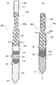
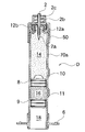
- FIG. 1A and 1B are cross-sectional views of a three-component mixing apparatus according to a first embodiment for explaining the outline of the present invention.
- FIG. 2 is a front view showing a state before the three-component mixing apparatus according to the second embodiment of the present invention is assembled.
- FIG. 3 (A) is a partially broken sectional view of the first member constituting the syringe employed in the three-component mixing apparatus according to the second embodiment of the present invention
- FIG. 3 (B) is FIG. 3 (A).
- FIG. 4A is a cross-sectional view showing the cap removed from both ends of the main body of the second member constituting the syringe according to the second embodiment of the present invention, and FIG.
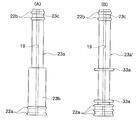
- FIG. 5A is a front view of a plunger main body employed in the second embodiment of the present invention
- FIG. 5B is a modification thereof.
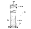
- FIG. 6 is a partially broken sectional view of a chemical solution container employed in the second embodiment of the present invention.
- FIG. 7 is a front view of a syringe composed of a first member and a second member according to the second embodiment of the present invention.
- FIG. 8 relates to the second embodiment of the present invention, and is a front view of a plunger composed of a chemical solution container and a plunger body.
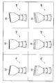
- FIGS. 10 (A) to 10 (C) relate to a second embodiment of the present invention, in which the third drug and the second drug are mixed after the syringe and the plunger are integrated together. It is sectional drawing which shows the change of.
- FIGS. 11 (A) to 11 (C) relate to a second embodiment of the present invention, in which a mixed medicine of a third medicine and a second medicine and a first medicine are mixed to form a three-component It is sectional drawing which shows a change when is mixed.
- FIG. 10 (A) to 10 (C) relate to a second embodiment of the present invention, in which the third drug and the second drug are mixed after the syringe and the plunger are integrated together. It is sectional drawing which shows the change of.
- FIGS. 11 (A) to 11 (C) relate to a second embodiment of the present invention, in which a mixed medicine of a third medicine and a second medicine and a first medicine are mixed to form a three-component It is sectional drawing which shows
- FIG. 12 (A) is a cross-sectional view showing a state in which the lid and the brush member are exchanged after the three chemicals are mixed in the three-component mixing apparatus of the second embodiment of the present invention
- FIG. It is a front view which shows the use condition of a three-component mixing apparatus.
- FIG. 13A is an exploded cross-sectional view of another chemical liquid container that replaces the chemical liquid container shown in FIG. 6, and
- FIG. 13B is a cross-sectional view of the chemical liquid container after the aluminum cap is assembled in a tightening manner.
- FIG. 14 is a list showing various examples of the brush member shown in FIG.
- FIG. 15 is a perspective view of a pipe-shaped nozzle that replaces the brush member.
- FIG. 16 is a sectional view of a syringe according to the third embodiment of the present invention.
- FIG. 17 is a sectional view of the three-component mixing apparatus of the third embodiment.
- the three-component mixing apparatus 300 includes a plunger 160 in which a chemical solution container 180 is accommodated on the rear end side with respect to the cylindrical syringe 100 in which the first drug 130 and the second drug 140 are accommodated in advance. It is constructed by assembling.
- the third medicine 170 is introduced into the syringe 100 through the through-hole 150 by pushing the bottom of the medicine container 180, and the plunger 160 is pushed against the syringe 100, whereby the medicine liquid provided in the plunger 160 is provided.
- This is a device that mixes the third medicine 170 in the container 180, the first medicine 130 in the syringe 100, and the second medicine 140 in the syringe 100.
- the first gasket 110 and the second gasket 120 are accommodated in the cylindrical syringe 100 with a predetermined distance therebetween, and these medicine discharge ports are provided.
- the first medicine 130 and the second medicine 140 are accommodated in advance in two chambers sealed by the 171, the first gasket 110, and the second gasket 120.
- a plunger main body 160a having a through hole 150 formed in the axial direction is prepared in advance, and a chemical solution container 180 containing a third medicine 170 is attached to the rear end side of the plunger main body 160a.
- the plunger 160 is comprised.
- the plunger 160 is pushed into the syringe 100, first, the third medicine 170 in the chemical solution container 180 is introduced into the syringe 100, and then the plunger 160 is further pressed, and the second gasket 120 is moved to the second. To a position matching the bypass groove 85.
- the second gasket 120 moves to a position that matches the second bypass groove 85, a gap is formed around the second gasket 120, so that this gap becomes a drug passage, and the third via the gap.
- the medicine 170 and the second medicine 140 are mixed.
- the plunger 160 when the plunger 160 is pressed, the plunger 160 comes into contact with the second gasket 120 located at a position matching the second bypass groove 85. Thereafter, the plunger 160 that contacts the third medicine 170 and the second medicine 140 is further pressed, so that the second gasket 120 is brought into contact with the second medicine 140 and the third medicine 170. It moves with the mixed medicine and the first gasket 110. As a result, as shown in FIG. 1B, the first gasket 110 is moved to a position that matches the first bypass groove 80.
- the first gasket 110 moves to a position that matches the first bypass groove 80, a gap is formed around the first gasket 110.
- a mixed drug of the second drug 140 and the third drug 170 and the first drug 130 are mixed in the syringe 100.
- the three-component mixing device 300 of the present invention is a device that discharges the medicine in which the three components are mixed from the medicine discharge port 171 on the distal end side.
- the cylindrical body of the syringe 100 is composed of one member, but the cylindrical body of the syringe may be composed of two or more members.
- the cylindrical body of the syringe A is composed of two members.
- FIG. 2 is a front view showing the three-component mixing device 30 according to the second embodiment of the present invention in an exploded state
- FIGS. 3A and 3B are first views used in the three-component mixing device 30 of FIG. 4 is a partially broken sectional view of the member 1 and its top view
- FIG. 4A is a sectional view showing the caps removed from both ends of the main body of the second member constituting the syringe according to the second embodiment of the present invention
- 4B is a cross-sectional view when caps are attached to both ends of the main body of the second member shown in FIG.
- the three-component mixing device 30 of the second embodiment has various uses as a device for mixing three components, but in the following description, as an example of a three-component drug, an apparatus used for mixing adhesives explain.
- the syringe is made up of two members, the first member 1 shown in FIG. 3 (A) and the second member 7 shown in FIG. 4 (A). A is configured.
- the second member 7 is slidably mounted in the first member 1.
- the three-component mixing device 30 includes a syringe A (FIG. 7) composed of the first member 1 and the second member 7, and a plunger in which the container body 20 a (FIG. 8) of the chemical solution container 20 is combined with the plunger body 23 a. B.
- the first member 1, the second member 7, the plunger main body 23a, and the container main body 20a are preferably made of a transparent member so that the state of the inside can be confirmed.
- the main body 1a of the first member 1 is formed in a substantially cylindrical shape, and the medicine discharge port 2 formed by opening on the distal end side is formed in advance on the needle portion 2a protruding inward. It communicates with the internal space 1b through the through-hole.
- an inner screw 2c is formed on the inner peripheral surface of the plug portion 2b formed so as to surround the periphery of the medicine discharge port 2 of the main body 1a.
- the brush member 4 is connected to the medicine discharge port 2 so that the lid 3 communicates with the drug discharge port 2 with respect to the drug discharge port 2 provided on the distal end side of the main body 1 a of the first member 1. These are each selectively and detachably attached. In addition, since the front end of the lid 3 is closed, no medicine or the like leaks from the inside of the lid 3 to the outside. Therefore, it is preferable to use the lid 3 until the work of mixing the internal medicine is performed.
- notched grooves 5 and 5 are formed at positions facing each other in the length direction, that is, positions different by 180 degrees.
- the number of the notch grooves 5 is not limited to two, and it is sufficient that at least one notch groove 5 is formed on the outer peripheral surface of the main body 1a of the first member 1.
- a finger hook flange 6 is provided at the base end portion of the main body 1a of the first member 1.
- the finger-hanging flange 6 may be formed of a separate member or may be formed integrally.
- the second member 7 has a first bypass groove 10 and a second bypass groove 11 facing outwardly while being separated from each other by a predetermined distance from the axial inner peripheral surface of the main body 7a. Bulge and formed.
- the first gasket 8 and the second gasket 9 are mounted with the second bypass groove 11 interposed therebetween.
- the first gasket 8 and the second gasket 9 are made of rubber, synthetic resin, or the like. Further, the leakage of the first medicine 15 and the second medicine 17 is prevented by the rubber plug 12a and the aluminum cap 12b.
- the outermost cap 12c may be made of metal, but is formed of synthetic resin in this embodiment.
- the first chamber 14 is located between the rubber plug 12a and the first gasket 8, and A second chamber 16 is formed between the gasket 8 and the second gasket 9, and a third chamber 18 is formed between the second gasket 9 and the cap 13. Then, the first medicine 15 and the second medicine 17 are accommodated in the first room 14 and the second room 16 in advance.
- the plunger main body 23a has different diameters between the rear end portion 23c and the front end portion 23b. Moreover, the through-hole 19 is formed in the plunger main body 23a over the both ends. Further, the rear end portion 23c and the front end portion 23b of the plunger main body 23a are provided with seal portions 22b and 22a, respectively. Although these seal parts 22a and 22b may be formed integrally with the plunger main body 23a, they may be formed separately.
- the diameters may be the same, and the rings 33a and 33a for the handle may be provided apart from each other by a predetermined distance.
- handle rings 33a and 33a are provided as described above, the operation when the plunger main body 23a 'is pushed into the container main body 20a shown in FIG. 6 can be easily performed.
- Plunger main bodies 23a and 23a ' are preferably formed of a chemical-resistant polypropylene resin or the like, although it varies depending on the type of chemicals constituting the adhesive.
- the chemical container 20 in which the third medicine 21 is accommodated is composed of a container body 20a and a lid 20b. Further, it is preferable that a rubber plug 20c is attached to the lid 20b, and a resin film, preferably a fluororesin film, is attached to the liquid contact surface of the rubber plug 20c. Moreover, it is preferable that the container main body 20a is formed from chemical-resistant glass. Such a container main body 20a is attached to the plunger main body 23a to constitute the plunger B as shown in FIG.
- a substantially convex bottom plate member 24 having a large bottom surface is attached to the container body 20a. If the bottom plate member 24 is thus attached to the container body 20a, the container body 20a can be prevented from falling. At the time of shipment, after the third medicine 21 is accommodated in the container body 20a, a lid body 20b with a rubber plug 20c is attached to the container body 20a.
- a three-component mixing kit is constituted by the syringe A and the plunger B before use, and is assembled and used at the time of use.
- the first drug 15 is a polymer (powder)
- the second drug 17 is It is a catalyst (solid or liquid)
- the third drug 21 is a monomer (liquid).
- examples of the polymer (powder) that becomes the first drug 15 include a powder made of a methacrylate polymer and a powder made of an acrylate polymer.
- the catalyst (liquid) to be the second drug 17 for example, an organic boron compound typified by trialkylboron or a partial oxide thereof, and an organic boron compound are used, for example, an aprotic solvent or an aprotic compound.
- an organic boron compound for example, an aprotic solvent or an aprotic compound.
- examples thereof include a liquid dissolved in a solvent such as a mixed solvent obtained by mixing a small amount of alcohol with an organic solvent.
- examples of the monomer (liquid) to be the third drug 21 include methacrylate and acrylate represented by methyl methacrylate and 4-methacryloxyethyl trimellitic anhydride.
- the first member 1 and the second member 7 containing the two components are taken out from the three component mixing kit. Then, the cap 12c and the cap 13 are removed from both ends of the main body 7a of the second member 7. When the cap 12c is removed, the aluminum piece is detached from the central portion of the top plate of the aluminum cap 12b. In the case where the cap 12c is not used, an aluminum cap having a hole from the beginning may be used. The cap 13 may be removed later.
- the lid 3 is mounted on the tip side of the first member 1, and then the second member 7 is inserted into the first member 1.
- the first bypass groove 10 and the second bypass groove 11 bulged outward from the main body 7 a of the second member 7 are aligned with the cutout groove 5 of the first member 1.
- the combination of the first member 1 and the second member 7 constitutes a syringe A as shown in FIG.
- the rubber plug 12a is penetrated by the needle portion 2a. Thereby, a hole through which the medicine and the mixed medicine flow from the medicine discharge port 2 is formed.
- the lid 20b While constituting the syringe A as described above, the lid 20b is removed from the container body 20a containing the third medicine 21 as shown in FIG. 6, and the plunger body 23a is press-fitted into the container body 20a. Thereby, the plunger B shown in FIG. 8 is comprised.
- FIG. 10 (A) is a view showing a three-component mixing device 30 in which a plunger B is assembled to a syringe A.
- FIG. 10 (A) is a view showing a three-component mixing device 30 in which a plunger B is assembled to a syringe A.
- the medicine discharge port 2 is in an upward orientation during the medicine mixing, and that the lid 3 is slightly loosened to release air as described above.
- 10A first, the bottom of the container body 20a is pushed in the direction of arrow E without moving the plunger body 23a relative to the syringe A.
- the third medicine 21 in the plunger B is pushed into the syringe A through the through-hole 19 by pushing the bottom of the container main body 20a. It is introduced into the third room 18.
- the second gasket 9 moves to the medicine discharge port 2 side. In this manner, the second gasket 9 moves to the medicine discharge port 2 side and reaches the position where the second gasket 9 matches the second bypass groove 11. When the second gasket 9 reaches a position that matches the second bypass groove 11, the second gasket 9 becomes immovable at this position. At this time, a gap is formed around the second gasket 9 to become a drug passage. Therefore, the third chamber 18 and the second chamber 16 communicate with each other through a gap formed around the second gasket 9.
- the second medicine (catalyst) 17 in the second chamber 16 and the third medicine 21 sent from the plunger B are mixed as shown in FIG. become.
- the first gasket 8 reaches a position that matches the first bypass groove 10. Then, the first gasket 8 cannot be moved at this position. And a clearance gap is formed around the 1st gasket 8, and becomes a chemical
- the first medicine 15 accommodated in the first room 14 and the mixed medicine of the second medicine 17 and the third medicine 21 mixed in the first room 14 are moved in the first room 14. Mix together.
- the three components are mixed as shown in FIG.
- the lid 3 is securely tightened. If the three-component mixing device 30 is vibrated vigorously in the vertical direction, for example, for about 20 seconds, the three components are mixed substantially uniformly.
- the three-component mixing device 30 can obtain a desired adhesive strength because a predetermined amount is mixed by one mixing.
- a predetermined amount can be obtained by increasing the number of three-component mixing devices 30 to two.
- the case where the first medicine 15 is a powder has been described. However, even if all the medicines including the first medicine 15 are liquid, they can be mixed. Further, the second drug is not limited to a liquid and may be a solid.
- the material of the constituent elements such as the first member 1 and the plunger main body 23a is not particularly mentioned, but it is preferable that the material is formed of an appropriate material corresponding to the medicine to be used.
- the lid 20b is attached with a screw type to the container body 20a in which the third medicine 21 is accommodated is shown.
- the attachment of the lid is not limited to a screw type.
- the rubber plug 28 is first press-fitted into the container main body 26, and then the aluminum cap 27 is fitted into the container main body 26.
- the aluminum cap 27 may be attached to the container body 26 by bending the opening end surface of the aluminum cap 27 inward. That is, the lid body made of the aluminum cap 27 can be attached to the container body 26 by a tightening method.
- a plastic lid (not shown) is attached to the outside of the aluminum cap 27. After removing the plastic lid, the rubber cap 28 can be removed together with the aluminum cap 27.
- a fluororesin film 29 such as Teflon (registered trademark) on the lower surface of the rubber plug 28.
- the tip surface forming the discharge part 32 of the brush member is formed obliquely, it is possible to easily apply the adhesive.
- the brush member 4S has shown the standard form.
- the discharge part 32 is inclined at a predetermined angle.
- the brush members 4L ′ and 4R ′ have the discharge portion 32 inclined at a predetermined angle in the same manner as the brush member 4S ′.
- the brush members 4L and 4L ′ are formed so as to be inclined obliquely so that one end of the brush members 4L rises to the left in FIG. 14, and these brush members 4L and 4L ′ are suitable for use with the left hand. .
- the brush members 4R and 4R ′ are formed so as to be inclined obliquely so that the other end thereof is raised to the right in FIG. 14, and these brush members 4R and 4R ′ are suitable for use with the right hand.
- a pipe-like nozzle 4A can be used as shown in FIG.
- FIG. 16 shows the syringe D employed in the third embodiment.
- a substantially cylindrical outer front end portion on which a medicine discharge port of the syringe body is formed is formed by a separate member, and a finger hook flange is formed by a separate member from the syringe body. This is different from the first and second embodiments.
- the syringe D is formed with a first bypass groove 10 and a second bypass groove 11 spaced apart from the cylindrical syringe body 70a by a predetermined distance.
- a first gasket 8 and a second gasket 9 are slidably disposed in the internal space.
- the rubber plug 12a, the aluminum cap 12b, and the like are attached to the mouth plug portion 2b as in the second embodiment.
- the substantially cylindrical outer front end portion 50 in which the medicine discharge port 2 of the syringe body 70a is formed is formed as a separate member. Furthermore, the finger hook flange 6 is formed as a separate member from the syringe body 70a. And this outside front-end
- the outer front end portion 50 corresponds to the vicinity of the plug portion 2b and the needle portion 2a of the first member 1 shown in FIG.
- the lid 3 or the brush member 4 is selectively attached to the outer front end portion 50.
- the lid 3 shown in FIG. 3 has no through hole formed in the axial direction, but a lid in which a through hole is formed in advance in the axial direction can also be adopted. If the through hole is formed in this way, air can be freely ventilated by interposing a porous filter member such as a sponge in the middle of the through hole. Employing such a lid eliminates the need for loosening to remove air.
- the syringe D formed as described above can be used in place of the syringe A.
- the three-component mixing apparatus 90 shown in FIG. 17 can be comprised.
- the three-component mixing device 90 if the plunger B is pushed into the syringe D side, the third medicine 21 is first introduced into the third chamber 18 of the syringe D as in the case of the second embodiment, Subsequently, the 3rd chemical
- the number of parts is smaller than that in the second embodiment, so that the assembly workability is good and it can be manufactured at low cost.
- each component such as a plunger, syringe, gasket, or cap
- an appropriate material is selected according to the drug to be used, and the materials disclosed in the above-described embodiments are used. It is not limited at all.
- the present invention can be preferably used for mixing an adhesive used in a surgical operation or a dental operation (or treatment), but can also be used as an adhesive for dental materials or an adhesive for industrial products. Applicable.
Abstract
[課題]例えば、外科用手術や歯科用手術(または処置)などで用いられる3成分混合接着剤を混合するにあたり、これら3成分の薬剤を誰でも容易に、かつ均一に混合することができる3成分混合装置を提供する。 [解決手段]先端側に薬剤吐出口が形成されるとともに、第1のガスケットと第2のガスケットとが摺動自在に配置され、前記薬剤吐出口と前記第1のガスケットとの間に第1の薬剤が収容され、前記第1のガスケットと第2のガスケットとの間に第2の薬剤が収容されたシリンジと、軸方向に貫通孔が形成され、かつ第3の薬剤が収容された薬液容器が後端側に着脱自在に装着され、さらに前記シリンジに対して先端側から摺動自在に挿入されたプランジャーと、を備え、前記プランジャーを、前記シリンジの後端側から先端側に向かって摺動させることにより、前記薬液容器内の前記第3の薬剤を、前記貫通孔を介して前記シリンジ内に導入するとともに、前記薬液容器内の前記第3の薬剤と前記シリンジ内の前記第2の薬剤と前記第1の薬剤とを前記シリンジ内で順次混合し、3成分が混合された薬剤を、前記薬剤吐出口を介して外方に吐出させるように構成された3成分混合装置とする。
Description
本発明は、例えば、外科用手術や歯科用手術(または処置)などに用いられる3成分混合接着剤の混合容器として好適な3成分混合装置および3成分混合キットに関する。
例えば、外科用手術や歯科用手術(または処置)では、縫合糸による縫合が一般に行われている。この縫合糸による縫合では、人の手による長時間の施術が行われるため、感染のリスクを完全にはぬぐい去ることができない。しかも、術後に鮮明な痕跡が広い範囲に残ってしまうことから、近年になって、外科用手術や歯科用手術に縫合糸と接着剤が兼用で、あるいは接着剤が単独で用いられる場合がある。このように傷口の閉鎖に接着剤を用いれば、施術時の感染のリスクが減少するのは勿論のこと、術後の審美性を一段と向上させることができる。
外科用手術や歯科用手術(または処置)などに用いられる接着剤としては、2種以上の成分が混合して使用される場合が多い。従来このような接着剤を用いる場合、これら薬剤は予め別々の容器内に充填される。そして、使用時に第1成分容器と第2成分容器とのキャップを外し、どちらかの容器に他方の薬剤を移し換えて用いたり、新たな容器に各々の薬剤を入れたり、さらに第3の薬剤を用いる場合は、二種の薬剤が混合された容器内に、第3の薬剤を続けて加えることが一般に行われているが、混合薬剤が3成分であり、使用時にこれら3成分を適量に、しかも均一に混合する作業は煩雑で改善が求められている。
ところで、2成分混合接着剤の混合としては、特許文献1のように、予め2成分を1つのシリンジ内に分離して充填しておき、使用時にシリンジに対してプランジャーを押圧することにより、シリンジ内に分離されている2成分を混合する装置が普及されている。しかしながら、3成分の薬剤を混合する接着剤もあり、このようなことを誰でも容易にできる3成分混合装置が求められているのが実情である。
本発明は、このような従来の実情に鑑み、例えば、外科用手術や歯科用手術(または処置)などで用いられる3成分混合接着剤を混合するにあたり、これら3種の薬剤を誰でも容易に、かつ均一に混合することができる3成分混合装置を提供することを目的としている。
さらに本発明は、3成分混合接着剤に使用されて好適な3成分混合キットを提供することを目的としている。
上記目的を達成するため、本発明に係る3成分混合装置は、
先端側に薬剤吐出口が形成されるとともに、第1のガスケットと第2のガスケットとが摺動自在に配置され、前記薬剤吐出口と前記第1のガスケットとの間に第1の薬剤が収容され、前記第1のガスケットと第2のガスケットとの間に第2の薬剤が収容されたシリンジと、
軸方向に貫通孔が形成され、かつ第3の薬剤が収容された薬液容器が後端側に着脱自在に装着され、さらに前記シリンジに対して先端側から摺動自在に挿入されたプランジャーと、
を備え、
前記プランジャーを、前記シリンジの後端側から先端側に向かって摺動させることにより、前記薬液容器内の前記第3の薬剤を、前記貫通孔を介して前記シリンジ内に導入するとともに、
前記薬液容器内の前記第3の薬剤と前記シリンジ内の前記第2の薬剤と前記第1の薬剤とを前記シリンジ内で順次混合し、3成分が混合された薬剤を、前記薬剤吐出口を介して外方に吐出させるように構成されていることを特徴とする。
このような構成であれば、3つの薬剤の均一混合を容易に行うことができる。
ここで本発明では、
前記シリンジには、前記シリンジの内表面から外表面に向かって膨出して形成された第1のバイパス溝と第2のバイパス溝とがそれぞれ設けられ、
前記第2のバイパス溝と合致する位置に前記第2のガスケットが移動されたときに前記第2のガスケットの両側に薬剤通路が形成され、
前記第1のバイパス溝と合致する位置に前記第1のガスケットが移動されたときに前記第1のガスケットの両側に薬剤通路が形成されることが好ましい。
前記シリンジには、前記シリンジの内表面から外表面に向かって膨出して形成された第1のバイパス溝と第2のバイパス溝とがそれぞれ設けられ、
前記第2のバイパス溝と合致する位置に前記第2のガスケットが移動されたときに前記第2のガスケットの両側に薬剤通路が形成され、
前記第1のバイパス溝と合致する位置に前記第1のガスケットが移動されたときに前記第1のガスケットの両側に薬剤通路が形成されることが好ましい。
このような構成であれば、第3の薬剤と第2の薬剤、および、この2成分混合薬剤と第1の薬剤とをバイパス溝の周囲に形成される薬剤の通路を介して混合することができる。
さらに本発明では、
前記シリンジには、前記プランジャーを摺動させるための指掛けフランジが具備されていることが好ましい。
前記シリンジには、前記プランジャーを摺動させるための指掛けフランジが具備されていることが好ましい。
このような構成であれば、プランジャーを押圧して薬剤を混合する際の作業を容易に行うことができる。
また本発明では、
前記薬液容器に、転倒防止用の底板部材が具備されていることが好ましい。
前記薬液容器に、転倒防止用の底板部材が具備されていることが好ましい。
このような構成であれば、薬液容器を自立した状態に保持することができる。
さらに本発明では、
前記シリンジは、前記薬剤吐出口を穿孔する針部材を備えていることが好ましい。
前記シリンジは、前記薬剤吐出口を穿孔する針部材を備えていることが好ましい。
この針部材により薬剤が流れる孔を穿孔することができる。
また本発明では、
前記第1の薬剤が粉体または液体、前記第2の薬剤が液体または固体、前記第3の薬剤が液体であっても良い。
前記第1の薬剤が粉体または液体、前記第2の薬剤が液体または固体、前記第3の薬剤が液体であっても良い。
これにより、第1の薬剤が粉体または液体、第2の薬剤が液体または固体、第3の薬剤が液体である場合に、最終ユーザーが直ちに3成分を混合して使用することができる。
また、本発明に係る3成分混合キットは、
先端側に薬剤吐出口が形成されるとともに、第1のガスケットと第2のガスケットとが摺動自在に配置され、前記薬剤吐出口と前記第1のガスケットとの間に第1の薬剤が収容され、前記第1のガスケットと第2のガスケットとの間に第2の薬剤が収容されたシリンジと、
軸方向に貫通孔が形成され、かつ第3の薬剤が収容された薬液容器が後端側に着脱自在に装着され、さらに前記シリンジに対して先端側から摺動自在に挿入されたプランジャーと、
から構成されていることを特徴としている。
先端側に薬剤吐出口が形成されるとともに、第1のガスケットと第2のガスケットとが摺動自在に配置され、前記薬剤吐出口と前記第1のガスケットとの間に第1の薬剤が収容され、前記第1のガスケットと第2のガスケットとの間に第2の薬剤が収容されたシリンジと、
軸方向に貫通孔が形成され、かつ第3の薬剤が収容された薬液容器が後端側に着脱自在に装着され、さらに前記シリンジに対して先端側から摺動自在に挿入されたプランジャーと、
から構成されていることを特徴としている。
このような3成分混合キットによれば、持ち運びが便利で、最終ユーザーが直ちに3成分を混合して使用することができる。
また、本発明に係る3成分混合キットでは、
前記第1の薬剤が粉体または液体、前記第2の薬剤が液体または固体、前記第3の薬剤が液体であっても良い。
前記第1の薬剤が粉体または液体、前記第2の薬剤が液体または固体、前記第3の薬剤が液体であっても良い。
このような3成分混合キットによれば、例えば、外科用手術や歯科用手術(または処置)などを行う場合に最終ユーザーの使い勝手が好適である。
本発明によれば、3つの薬剤の均一混合を容易に行うことができる。また、3成分を誰でも容易にかつ均一に適量を混合することができる。
またシリンジに、外表面に向かって膨出して形成された第1のバイパス溝と第2のバイパス溝が形成されていれば、ガスケットが第1のバイパス溝または第2のバイパス溝と合致する位置に移動したときに、ガスケットの周囲に隙間が形成されるので、この隙間を薬剤の通路として薬剤の混合を行うことができる。
さらに、プランジャーに指掛けフランジが具備されていれば、プランジャーを押圧して薬剤を混合する際の作業を容易に行うことができる。
また、薬液容器に転倒防止用の底板部材が具備されていれば、薬液容器を自立した状態に保持することができる。
さらに、シリンジに針部材が具備されていれば薬剤が流れる孔を穿孔することができる。
また、第1の薬剤が粉体または液体、第2の薬剤が液体または固体、第3の薬剤が液体であれば、外科用手術や歯科用手術(または処置)に用いられる接着剤の混合用に、本発明の3成分混合装置を有効利用することができる。
よって、最終ユーザーが外科用手術や歯科用手術(または処置)などで接着剤が必要な場合に、その場で直ちに3成分を混合して接着剤として使用することができる。
以下、本発明について説明する。
<第1実施例>
先ず、本発明の概略を、図1(A),(B)に示した第1実施例を参照しながら説明する。
先ず、本発明の概略を、図1(A),(B)に示した第1実施例を参照しながら説明する。
第1実施例の3成分混合装置300は、第1の薬剤130と第2の薬剤140が予め収容された筒状のシリンジ100に対し、後端側に薬液容器180が収容されたプランジャー160を組み付けて構成されるものである。第3の薬剤170を薬液容器180の底部を押すことにより貫通孔150を介してシリンジ100に導入し、そしてプランジャー160をシリンジ100に対して押圧することにより、プランジャー160に具備された薬液容器180内の第3の薬剤170と、シリンジ100内の第1の薬剤130と、シリンジ100内の第2の薬剤140とを混合する装置である。
すなわち、本発明の第1実施例の3成分混合装置300では、筒状のシリンジ100内に第1のガスケット110と第2のガスケット120とを所定間隔離間して収容し、これらの薬剤吐出口171と第1のガスケット110と第2のガスケット120とにより封止された2つの室内に、第1の薬剤130と第2の薬剤140とを予め収容している。
一方、軸方向に貫通孔150が形成されたプランジャー本体160aを予め用意し、このプランジャー本体160aの後端側に第3の薬剤170が収容された薬液容器180を装着する。これにより、プランジャー160を構成する。
そして、プランジャー160をシリンジ100内に押し込み、先ず、薬液容器180内の第3の薬剤170をシリンジ100内に導入し、次いで、さらにプランジャー160を押圧し、第2のガスケット120を第2のバイパス溝85と合致する位置に移動させる。
第2のガスケット120が第2のバイパス溝85と合致する位置に移動すれば、第2のガスケット120の周囲に隙間が形成されるので、この隙間が薬剤通路となり、その隙間を介して第3の薬剤170と第2の薬剤140とが混ざりあう。
さらにプランジャー160を押圧することにより、第2のバイパス溝85と合致する位置にあった第2のガスケット120にプランジャー160が当接する。しかる後、上記第3の薬剤170と第2の薬剤140とを当接したプランジャー160をさらに押圧することにより、第2のガスケット120が、第2の薬剤140と第3の薬剤170との混合薬剤と、第1のガスケット110とを伴って移動する。これにより、図1(B)に示したように、第1のガスケット110を、第1のバイパス溝80と合致する位置に移動させる。
このように、第1のガスケット110が第1のバイパス溝80と合致する位置に移動することにより、第1のガスケット110の周囲に隙間が形成されるので、この隙間が薬剤通路となって、第2の薬剤140と第3の薬剤170との混合薬剤と、第1の薬剤130とが、シリンジ100内で混合されるようになっている。
そして、本発明の3成分混合装置300は、その3成分が混合された薬剤を先端側の薬剤吐出口171から排出させる装置である。
<第2実施例>
以下、本発明の第2実施例について説明する。
以下、本発明の第2実施例について説明する。
第1実施例では、シリンジ100の筒体を一部材で構成したが、シリンジの筒体は二部材以上で構成しても良い。第2実施例では、図2~図14に示したように、シリンジAの筒体を二部材で構成している。
図2は、本発明の第2実施例による3成分混合装置30を分解した状態で示す正面図、図3(A),(B)は図2の3成分混合装置30で採用された第一部材1の一部破断面図とその上面図、図4(A)は本発明の第2実施例に係るシリンジを構成する第二部材の本体の両端部から、それぞれキャップを取り外して示す断面図、図4(B)は図4(A)に示した第二部材の本体の両端部に、それぞれキャップを取り付けたときの断面図である。
第2実施例の3成分混合装置30は、3成分を混合するための装置として様々な用途があるが、以下の説明では、3成分からなる薬剤の例として接着剤の混合に用いられる装置について説明する。
図2に示した第2実施例の3成分混合装置30では、図3(A)に示した第一部材1と、図4(A)に示した第二部材7との2部材により、シリンジAが構成されている。ここで第二部材7は、第一部材1内に摺動自在に装着される。
また3成分混合装置30は、第一部材1と第二部材7とからなるシリンジA(図7)と、プランジャー本体23aに薬液容器20の容器本体20a(図8)が組み合わされたプランジャーBとから構成される。
第一部材1と第二部材7とプランジャー本体23aと容器本体20aは、内部の様子を確認できるように透明部材からなることが好ましい。
図3に示したように、第一部材1の本体1aは、略筒状に形成され、先端側に開口して形成された薬剤吐出口2は、内方に突出した針部2aに予め形成されている貫通孔を介して内部空間1bに連通している。一方、本体1aの薬剤吐出口2の周囲を囲繞するように形成された口栓部2bの内周面には、内ネジ2cが形成されている。
第一部材1の本体1aの先端側に設けられた薬剤吐出口2に対し、この薬剤吐出口2を封止するように蓋体3が、薬剤吐出口2と連通するように刷毛部材4が、それぞれ選択的かつ着脱自在に取付けられる。なお、蓋体3は、先端が閉塞しているため、この蓋体3の内部から薬剤などが外部に漏れてしまうことはない。したがって、蓋体3は、内部の薬剤を混合する作業を行う時まで使用することが好ましい。
しかしながら、蓋体3を内ネジ2cに対し強く締め付けた場合には、本体1a内の空気抜きを行うことができない。そのため、空気抜きを行う必要があるときには蓋体3を若干緩めることにより空気通路を確保する必要がある。
また、この第一部材1の本体1aには、長さ方向の互いに対向する位置すなわち180度異なる位置に切欠溝5,5が形成されている。なお、この切欠溝5は2つに限定されず、第一部材1の本体1aの外周面に少なくとも1つ形成されていれば良い。第一部材1の本体1aの基端部には、指掛けフランジ6が具備されている。この指掛けフランジ6は別部材で構成しても良く、一体で形成しても良い。第一部材1と第二部材7とを組み付け、第一部材1の口栓部2bに蓋体3を取り付けたとき、図7に示したシリンジAが構成される。
第二部材7は、図4(A)に示したように、その本体7aの軸方向の内周面に所定間隔離反して第1のバイパス溝10と第2のバイパス溝11が外側に向かって膨出して形成されている。そして、第二部材7の本体7a内には、第1のガスケット8と第2のガスケット9とが第2のバイパス溝11を挟んで装着される。第1のガスケット8と第2のガスケット9は、ゴム,合成樹脂などにより形成されている。また、ゴム栓12aおよびアルミキャップ12bにより、第1の薬剤15と第2の薬剤17の漏洩が防止される。最外方のキャップ12cは、金属製であっても良いが、本実施例では、合成樹脂により形成されている。
第1のガスケット8と第2のガスケット9とが第2のバイパス溝11を挟んで装着されたとき、ゴム栓12aと第1のガスケット8との間に第1の部屋14が、第1のガスケット8と第2のガスケット9との間に第2の部屋16が、第2のガスケット9とキャップ13との間に第3の部屋18がそれぞれ構成される。そして、第1の部屋14と第2の部屋16内に予め第1の薬剤15と第2の薬剤17が収容される。
またプランジャー本体23aは、図5(A)に示したように、後端部23cと先端部23bとの間で径が異なっている。また、プランジャー本体23aには、その両端部に渡って貫通孔19が形成されている。さらに、プランジャー本体23aの後端部23cと先端部23bとには、シール部22b,22aがそれぞれ具備されている。これらシール部22a,22bは、プランジャー本体23aと一体で形成されていても良いが、別体で形成されていても良い。
また、図5(B)に示したプランジャー本体23a'のように径を同一とし、その途中に持ち手用のリング33a,33aを所定距離離反して設けても良い。
このように持ち手用のリング33a,33aが設けられていれば、プランジャー本体23a'を、図6に示した容器本体20aに対して押し込む際の作業を容易に行うことができる。
プランジャー本体23a,23a'は、接着剤を構成する薬剤の種類によっても異なるが、一般には耐薬品性のあるポリプロピレン樹脂などにより形成されていることが好ましい。
図6に示したように、第3の薬剤21が収容される薬液容器20は、容器本体20aと蓋体20bとから構成されている。また、蓋体20bにはゴム栓20cが装着され、ゴム栓20cの接液面には、樹脂製フィルム、好適にはフッ素樹脂フィルムが貼り付けされていることが好ましい。また、容器本体20aは、耐薬品性のガラスから形成されていることが好ましい。このような容器本体20aがプランジャー本体23aに装着されて図8に示したようなプランジャーBが構成される。
また、容器本体20aには、底面が大径に形成された略凸状の底板部材24が装着されていることが好ましい。このように容器本体20aに底板部材24が装着されていれば、容器本体20aの転倒を防止することができる。出荷時においては、この容器本体20aに第3の薬剤21が収容された後、容器本体20aに、ゴム栓20c付きの蓋体20bが装着される。
本発明の3成分混合装置は、使用前において、シリンジAとプランジャーBとにより3成分混合キットが構成され、使用時に組み立てて使用するようになっている。
以下に、第2実施例の3成分混合装置30を医療用の接着剤の混合に用いる場合について説明する。
ここで、3成分混合装置30が外科用手術や歯科用手術(または処置)の接着剤の混合に用いられる場合、第1の薬剤15はポリマー(粉体)であり、第2の薬剤17は触媒(固体または液体)であり、第3の薬剤21は、モノマー(液体)である。その場合、第一の薬剤15となるポリマー(粉体)としては、例えば、メタクリレート重合体からなる粉体及びアクリレート重合体からなる粉体が挙げられる。
また、第2の薬剤17となる触媒(液体)としては、例えば、トリアルキルホウ素もしくはその部分酸化物に代表される有機ホウ素化合物、及び、有機ホウ素化合物を、例えば非プロトン性溶媒、または非プロトン性溶媒に少量のアルコールを混合した混合溶媒などの溶媒に溶解した液体が挙げられる。
さらに、第3の薬剤21となるモノマー(液体)としては、例えば、メタクリル酸メチル、4-メタクリロキシエチルトリメリット酸無水物に代表されるメタクリレート及びアクリレートが挙げられる。
今、3成分混合キットから第一部材1と、2成分が収容された第二部材7とが取り出される。そして、第二部材7の本体7aの両端部からキャップ12cと、キャップ13とが取り外される。キャップ12cを取り外した際、アルミキャップ12bの天板の中央部分からアルミ片が外れる。なお、キャップ12cを使用しない場合には、アルミキャップ中央に最初から孔の開いたものを使用しても良い。また、キャップ13は後から取り外しても良い。
その後、第一部材1の先端側に蓋体3を装着してから、第一部材1内に第二部材7を挿入する。このとき第二部材7の本体7aの外方に膨出された第1のバイパス溝10、第2のバイパス溝11を第一部材1の切欠溝5内に合致させる。
第一部材1と第二部材7との組み合わせにより、図7に示したように、シリンジAが構成される。なお、このシリンジAを構成する場合に、空気抜きのため、図9に示したように蓋体3を若干緩めておくことが好ましい。
また、シリンジAを構成した後、第二部材7を第一部材1内にさらに押し込めば、針部2aによりゴム栓12aが貫通される。これにより、薬剤吐出口2から薬剤および混合薬剤が流れる孔が形成される。
上記のようにシリンジAを構成する一方、図6に示したように第3の薬剤21が収容された容器本体20aから蓋体20bを取り外し、その容器本体20aにプランジャー本体23aを圧入する。これにより、図8に示したプランジャーBを構成する。
このようにして、シリンジAとプランジャーBとを構成すれば、3成分混合作業の準備を完了することができる。
以下に、混合作業について説明する。
なお、図10~図12では、混合の順番を略時系列で示している。
図10(A)は、シリンジAにプランジャーBを組み付けた3成分混合装置30を示した図である。
3成分混合装置30において、薬剤混合の途中では、薬剤吐出口2が上に向く姿勢にし、さらに上述したように空気抜きのため蓋体3を若干緩めておくことが好ましい。図10(A)の姿勢から、先ず、プランジャー本体23aをシリンジAに対して移動させないまま、容器本体20aの底部を矢印E方向に押し込んでいく。このように、プランジャー本体23aをシリンジAに対して移動させないまま、先ず容器本体20aの底部を押すことによってプランジャーB内の第3の薬剤21を、貫通孔19を介してシリンジA内の第3の部屋18内に導入する。
この結果、図10(B)のようになる。
このようにして、第3の薬剤21がシリンジAの第3の部屋18内に導入された後、さらにプランジャーBの容器本体20aの底部を矢印E方向に押圧する。すると、第3の部屋18内の内圧が次第に高まることにより、図10(B)の状態から図10(C)の状態となる。
すなわち、第2のガスケット9が薬剤吐出口2側に移動する。このように、第2のガスケット9が薬剤吐出口2側に移動して、第2のガスケット9が第2のバイパス溝11と合致する位置に到達する。第2のガスケット9が第2のバイパス溝11と合致する位置に到達すると、第2のガスケット9はこの位置で移動不能となる。このとき第2のガスケット9の周囲に隙間が形成され、薬剤通路となる。よって、第3の部屋18と第2の部屋16との間が第2のガスケット9の周囲に形成された隙間を介して連通する。
これにより、第2の部屋16内の第2の薬剤(触媒)17と、プランジャーBから送られてきた第3の薬剤21とが、図11(A)に示したように、混ざりあうことになる。
この状態から、さらにプランジャーBを薬剤吐出口2側に向かって押し込むと、図11(B)に示したように、プランジャーBの先端側で第2のガスケット9を押圧し、第2の部屋16内の内圧が上がり、これに伴って第1のガスケット8が移動する。
その結果、第1のガスケット8が第1のバイパス溝10と合致する位置に到達する。すると、この第1のガスケット8がこの位置で移動不能となる。そして、第1のガスケット8の周囲に隙間が形成され、薬剤通路となる。これにより、第2の部屋16と第1の部屋14との間が連通状態となる。
これにより、第1の部屋14内に収容されていた第1の薬剤15と、先に混合された第2の薬剤17と第3の薬剤21との混合薬剤が、第1の部屋14内で混ざり合う。
最終的に図11(C)に示したように3成分が混合される。3成分が混合されたときには、蓋体3の緩みを確実に締める。そして、3成分混合装置30を上下方向に、例えば約20秒程度激しく振動させれば、3成分が略均一に混ざりあうことになる。
このようにして、3成分の混合が完了する。そして、最終的には、薬剤吐出口2に取付けられた蓋体3を取り外し、蓋体3の代わりに図12(A)に示したように刷毛部材4を取付ければ、使用前の準備が完了する。
この準備が完了した後、プランジャーBを薬剤吐出口2に向かって押し込めば、図12(B)に示したように、所望とする接着剤を刷毛部材4から適量を吐出させることができ、この接着剤を外科用手術や歯科用手術(または処置)などに用いることが可能になる。使用後は、専用容器などに入れられて集積され、その後、破棄される。
このように第2実施例による3成分混合装置30は、一回の混合で所定量同士が混合されるので、所望とする接着強度を得ることができる。また、多量の接着剤を用いる場合は、3成分混合装置30を2本,3本と増やすことによって、所定量を得ることができる。
また、第2実施例では、第1の薬剤15が粉体である場合について説明したが、この第1の薬剤15を含めて、全ての薬剤が液体であっても混合することができる。また、第2の薬剤は液体に限定されず、固体であっても良い。
また、第2実施例では、第一部材1、プランジャー本体23aなど、構成要素の材料に関しては、特に言及していないが、用いる薬剤に対応して適宜な材料で形成することが好ましい。
さらに、外科用手術や歯科用手術(または処置)に使用される接着剤の他、3成分の薬剤の混合に好ましく使用することができる。
また、第2実施例では、図6に示したように、第3の薬剤21が収容される容器本体20aに対し、ネジ式で蓋体20bが装着される例を示したが、薬剤本体に対する蓋体の取付けは、ネジ式に何ら限定されるものでない。
例えば、図13(A),(B)に示した薬液容器25のように、容器本体26に対して先ずゴム栓28を圧入し、その後、アルミキャップ27を容器本体26に嵌合し、次いで、図13(B)のようにアルミキャップ27の開口端面を内側に折曲させることにより、容器本体26にアルミキャップ27を取り付けても良い。すなわち、アルミキャップ27からなる蓋体を、まき締め式で容器本体26に取り付けることもできる。
この場合、容器本体26には、ネジ山は形成されず、開口端部の径が若干太く形成される。
なお、アルミキャップ27の外方には図示しないプラスチック蓋が装着される。このプラスチック蓋を外した後、アルミキャップ27とともにゴム栓28を外すことができる。
また、ゴム栓28の下面には、テフロン(登録商標)などのフッ素樹脂フィルム29を介在させておくことが好ましい。
また、刷毛部材の吐出部32を形成する先端面を斜めに形成すれば、接着剤を塗り易くすることができる。
なお、図14において、刷毛部材4Sは標準形を示している。
一方、刷毛部材4S'は、吐出部32が所定の角度、傾斜している。
また刷毛部材4L',4R'も刷毛部材4S'と同様に、吐出部32が所定の角度、傾斜している。
さらに、刷毛部材4L,4L'は、図14において一方の端部が左上がりとなるように斜めに傾斜して形成され、これらの刷毛部材4L,4L'は左手で使用するのに適している。
また、刷毛部材4R,4R'は、図14において他方の端部が右上がりとなるよう斜めに傾斜して形成され、これらの刷毛部材4R,4R'は右手で使用するのに適している。
このように、使用者の利き手に合わせて刷毛部材の傾斜角度を選択すれば、使い勝手が良好になる。また、接着剤を少量使用する場合には、図15に示したように、パイプ状のノズル4Aを使用することもできる。
<第3実施例>
図16~図17は本発明の第3実施例を示したものである。図16は第3実施例で採用されたシリンジDを示したものである。
図16~図17は本発明の第3実施例を示したものである。図16は第3実施例で採用されたシリンジDを示したものである。
この第3実施例では、シリンジにおいて、シリンジ本体の薬剤吐出口が形成された略筒状の外側先端部が別部材で形成されている点、および指掛けフランジがシリンジ本体と別部材で形成されている点が、第1実施例及び第2実施例と異なっている。
他の点は第2実施例と大きく変更はないので、同一要素に同一符号を付して詳細な説明を省略する。
図16に示したように、このシリンジDは、筒状のシリンジ本体70aに所定間隔離間して第1のバイパス溝10と第2のバイパス溝11が形成されている。そして、内部空間に第1のガスケット8と第2のガスケット9が摺動可能に配置されている。さらに口栓部2bにゴム栓12aやアルミキャップ12bなどが装着される点は第2実施例と同様である。
一方、第3実施例のシリンジDでは、シリンジ本体70aの薬剤吐出口2が形成された略筒状の外側先端部50が、別部材で形成されている。さらに、指掛けフランジ6がシリンジ本体70aと別部材で形成されている。そして、この外側先端部50がシリンジ本体70aに使用時において一体的に嵌合されている。
この外側先端部50は、図3に示した第一部材1の口栓部2b、針部2a付近に相当するものである。この外側先端部50に、蓋体3あるいは刷毛部材4が選択的に装着される。
このような外側先端部50がシリンジ本体70aに装着されることにより、ゴム栓12aに孔が開けられる。
ここで、図3に示した蓋体3は軸方向に貫通孔が形成されていないが、軸方向に予め貫通孔を形成した蓋体を採用することもできる。このように貫通孔が形成されていれば、貫通孔の途中にスポンジのような多孔質性のフィルター部材を介在させることにより空気抜きを自由に行うことができる。このような蓋体を採用すれば、空気抜きのために緩める作業が不要となる。
上記のように形成されたシリンジDをシリンジAに代えて使用することができる。そして、図17に示した3成分混合装置90を構成することができる。
3成分混合装置90において、プランジャーBをシリンジD側に押し込んでいけば、第2実施例の場合と同様に、先ず第3の薬剤21をシリンジDの第3の部屋18内に導入し、次いで、第3の薬剤21と第2の薬剤17とを混合し、さらにこの混合薬剤に第1の薬剤15を混合し、しかる後、振動させることにより3成分を均一に混合することができる。均一混合が完了した後、蓋体3に代えて刷毛部材4を取り付ければ3成分混合薬剤の塗布を行うことができる。
この第3実施例のような3成分混合装置90であれば、第2実施例よりも部品点数が少なくなるので、組立作業性が良好であるのは勿論のこと、安価に製造可能である。
なお、本発明において、プランジャーやシリンジ、ガスケット、あるいはキャップなど、各構成要素の材質は、用いる薬剤に対応して適宜な材料が選択されるものであり、上述した実施例に開示した材料に何ら限定されるものではない。
本発明は、外科用手術や歯科用手術(または処置)の際に使用される接着剤の混合に好ましく用いることができるが、さらに、歯科材料の接着剤として、あるいは工業製品の接着剤としても適用できる。
1 第一部材
1a 第一部材の本体
2 薬剤吐出口
2a 針部
2b 口栓部
2c 内ネジ
3 蓋体
4 刷毛部材
4A パイプ状のノズル
4S,4S',4L,4L',4R,4R' 刷毛部材
5 切欠溝
6 指掛けフランジ
7 第二部材
7a 第二部材の本体
8 第1のガスケット
9 第2のガスケット
10 第1のバイパス溝
11 第2のバイパス溝
12a ゴム栓
12b アルミキャップ
12c キャップ
13 キャップ
14 第1の部屋
15 第1の薬剤
16 第2の部屋
17 第2の薬剤
18 第3の部屋
19 貫通孔
20 薬液容器
20a 容器本体
20b 蓋体
20c ゴム栓
21 第3の薬剤
22a,22b シール部材
23a,23a' プランジャー本体
23b 先端部
23c 後端部
24 底板部材
25 薬液容器
26 容器本体
27 アルミキャップ
28 ゴム栓
29 フッ素樹脂フィルム
30 3成分混合装置
32 吐出部
33a 持ち手用のリング
50 外側先端部
70a シリンジ本体
80 第1のバイパス溝
85 第2のバイパス溝
90 3成分混合装置
100 シリンジ
110 第1のガスケット
120 第2のガスケット
130 第1の薬剤
140 第2の薬剤
150 貫通孔
160 プランジャー
160a プランジャー本体
170 第3の薬剤
180 薬液容器
300 成分混合装置
A シリンジ
B プランジャー
D シリンジ
Claims (8)
- 先端側に薬剤吐出口が形成されるとともに、第1のガスケットと第2のガスケットとが摺動自在に配置され、前記薬剤吐出口と前記第1のガスケットとの間に第1の薬剤が収容され、前記第1のガスケットと第2のガスケットとの間に第2の薬剤が収容されたシリンジと、
軸方向に貫通孔が形成され、かつ第3の薬剤が収容された薬液容器が後端側に着脱自在に装着され、さらに前記シリンジに対して先端側から摺動自在に挿入されたプランジャーと、
を備え、
前記プランジャーを、前記シリンジの後端側から先端側に向かって摺動させることにより、前記薬液容器内の前記第3の薬剤を、前記貫通孔を介して前記シリンジ内に導入するとともに、
前記薬液容器内の前記第3の薬剤と前記シリンジ内の前記第2の薬剤と前記第1の薬剤とを前記シリンジ内で順次混合し、3成分が混合された薬剤を、前記薬剤吐出口を介して外方に吐出させるように構成されていることを特徴とする3成分混合装置。 - 前記シリンジには、前記シリンジの内表面から外表面に向かって膨出して形成された第1のバイパス溝と第2のバイパス溝とがそれぞれ設けられ、
前記第2のバイパス溝と合致する位置に前記第2のガスケットが移動されたときに前記第2のガスケットの両側に薬剤通路が形成され、
前記第1のバイパス溝と合致する位置に前記第1のガスケットが移動されたときに前記第1のガスケットの両側に薬剤通路が形成されることを特徴とする請求項1に記載の3成分混合装置。 - 前記シリンジには、前記プランジャーを摺動させるための指掛けフランジが具備されていることを特徴とする請求項1または2に記載の3成分混合装置。
- 前記薬液容器に、転倒防止用の底板部材が具備されていることを特徴とする請求項1~3のいずれかに記載の3成分混合装置。
- 前記シリンジは、前記薬剤吐出口を穿孔する針部材を備えていることを特徴とする請求項1~4のいずれかに記載の3成分混合装置。
- 前記第1の薬剤が粉体または液体、前記第2の薬剤が液体または固体、前記第3の薬剤が液体であることを特徴とする請求項1~5のいずれかに記載の3成分混合装置。
- 先端側に薬剤吐出口が形成されるとともに、第1のガスケットと第2のガスケットとが摺動自在に配置され、前記薬剤吐出口と前記第1のガスケットとの間に第1の薬剤が収容され、前記第1のガスケットと第2のガスケットとの間に第2の薬剤が収容されたシリンジと、
軸方向に貫通孔が形成され、かつ第3の薬剤が収容された薬液容器が後端側に着脱自在に装着され、さらに前記シリンジに対して先端側から摺動自在に挿入されたプランジャーと、
から構成されていることを特徴とする3成分混合キット。 - 前記第1の薬剤が粉体または液体、前記第2の薬剤が液体または固体、前記第3の薬剤が液体であることを特徴とする請求項7に記載の3成分混合キット。
Applications Claiming Priority (2)
| Application Number | Priority Date | Filing Date | Title |
|---|---|---|---|
| JP2011034997 | 2011-02-21 | ||
| JP2011-034997 | 2011-02-21 |
Publications (1)
| Publication Number | Publication Date |
|---|---|
| WO2012115022A1 true WO2012115022A1 (ja) | 2012-08-30 |
Family
ID=46654404
Family Applications (1)
| Application Number | Title | Priority Date | Filing Date |
|---|---|---|---|
| PCT/JP2012/053922 WO2012115022A1 (ja) | 2011-02-21 | 2012-02-20 | 3成分混合装置および3成分混合キット |
Country Status (3)
| Country | Link |
|---|---|
| CN (2) | CN202751417U (ja) |
| TW (1) | TW201247265A (ja) |
| WO (1) | WO2012115022A1 (ja) |
Cited By (13)
| Publication number | Priority date | Publication date | Assignee | Title |
|---|---|---|---|---|
| EP3011990A1 (en) * | 2014-10-21 | 2016-04-27 | Sulzer Mixpac AG | Dual-chamber syringe |
| AU2018202628B2 (en) * | 2017-04-28 | 2019-03-14 | Heraeus Medical Gmbh | Bone cement application device with closure means on the delivery plunger |
| WO2019211858A1 (en) * | 2018-05-04 | 2019-11-07 | Sealantis Ltd. | Reconstitution and mixing systems |
| JP2020031862A (ja) * | 2018-08-29 | 2020-03-05 | リジェンティス株式会社 | 歯の漂白用のデバイス及びキット |
| EP3662990A1 (de) * | 2018-12-07 | 2020-06-10 | Heraeus Medical GmbH | Vorrichtung zum mischen eines knochenzements mit hohlraum zum monomertransfer |
| EP3662991A1 (de) * | 2018-12-07 | 2020-06-10 | Heraeus Medical GmbH | Vorrichtung zum mischen eines knochenzements mit hohlraum zum monomertransfer |
| WO2021013752A1 (en) * | 2019-07-19 | 2021-01-28 | Septodont Ou Septodont Sas Ou Specialites Septodont | Cartridge for dispensing a material |
| EP3791907A1 (fr) * | 2019-09-12 | 2021-03-17 | AD-HOC Scientific (Société par Actions Simplifiée à Associé Unique) | Pièce d'injection pour cartouche en verre de seringue |
| US11291490B2 (en) | 2018-10-25 | 2022-04-05 | Heraeus Medical Gmbh | Device for providing bone cement |
| WO2022089940A1 (en) * | 2020-10-26 | 2022-05-05 | Novo Nordisk A/S | A medical container for storing a liquid drug |
| US11324569B2 (en) | 2017-07-12 | 2022-05-10 | 3M Innovative Properties Company | Delivery system for a dental composition |
| US20220192784A1 (en) * | 2020-12-17 | 2022-06-23 | Sdi (North America), Inc. | Dental capsule |
| US11969195B2 (en) | 2018-10-25 | 2024-04-30 | Heraeus Medical Gmbh | Device for providing bone cement |
Families Citing this family (3)
| Publication number | Priority date | Publication date | Assignee | Title |
|---|---|---|---|---|
| TW201247265A (en) * | 2011-02-21 | 2012-12-01 | Mitsui Chemicals Inc | Device and kit for mixing three components |
| US20150351753A1 (en) | 2014-06-10 | 2015-12-10 | Ethicon Endo-Surgery, Inc. | Methods and Devices for Reinforcing a Staple Line |
| CN106572856A (zh) * | 2014-06-10 | 2017-04-19 | 伊西康内外科有限责任公司 | 用于密封缝合组织的方法和装置 |
Citations (8)
| Publication number | Priority date | Publication date | Assignee | Title |
|---|---|---|---|---|
| US3076456A (en) * | 1960-03-07 | 1963-02-05 | Elsie B Hunt | Hypodermic syringe |
| JPS51398B1 (ja) * | 1968-05-28 | 1976-01-07 | ||
| US4014330A (en) * | 1975-10-28 | 1977-03-29 | Abbott Laboratories | Disposable two-compartment syringe |
| WO1995017916A1 (fr) * | 1993-12-28 | 1995-07-06 | Tetsuro Higashikawa | Seringue |
| JPH08112358A (ja) * | 1994-10-19 | 1996-05-07 | Material Eng Tech Lab Inc | 多成分用注射器 |
| JPH1052491A (ja) * | 1996-08-09 | 1998-02-24 | Material Eng Tech Lab Inc | 注射器 |
| JP2005103274A (ja) * | 2003-09-30 | 2005-04-21 | 3M Espe Ag | シリンジアセンブリ |
| JP2005521478A (ja) * | 2002-03-28 | 2005-07-21 | エム.エル.アイ.エス プロジェクツ リミテッド | 多区画シリンジ |
Family Cites Families (3)
| Publication number | Priority date | Publication date | Assignee | Title |
|---|---|---|---|---|
| AU2005312310A1 (en) * | 2004-12-03 | 2006-06-08 | Duoject Medical Systems Inc. | Cartridge, device and method for pharmaceutical storage, mixing and delivery |
| ITAR20090017A1 (it) * | 2009-03-23 | 2010-09-24 | Nedo Magrini | Siringa, particolarmente per uso medico e veterinario, multicamera, monouso e precaricata |
| TW201247265A (en) * | 2011-02-21 | 2012-12-01 | Mitsui Chemicals Inc | Device and kit for mixing three components |
-
2012
- 2012-02-20 TW TW101105470A patent/TW201247265A/zh unknown
- 2012-02-20 WO PCT/JP2012/053922 patent/WO2012115022A1/ja active Application Filing
- 2012-02-21 CN CN2012200597216U patent/CN202751417U/zh not_active Expired - Lifetime
- 2012-02-21 CN CN2012100410505A patent/CN102641145A/zh active Pending
Patent Citations (8)
| Publication number | Priority date | Publication date | Assignee | Title |
|---|---|---|---|---|
| US3076456A (en) * | 1960-03-07 | 1963-02-05 | Elsie B Hunt | Hypodermic syringe |
| JPS51398B1 (ja) * | 1968-05-28 | 1976-01-07 | ||
| US4014330A (en) * | 1975-10-28 | 1977-03-29 | Abbott Laboratories | Disposable two-compartment syringe |
| WO1995017916A1 (fr) * | 1993-12-28 | 1995-07-06 | Tetsuro Higashikawa | Seringue |
| JPH08112358A (ja) * | 1994-10-19 | 1996-05-07 | Material Eng Tech Lab Inc | 多成分用注射器 |
| JPH1052491A (ja) * | 1996-08-09 | 1998-02-24 | Material Eng Tech Lab Inc | 注射器 |
| JP2005521478A (ja) * | 2002-03-28 | 2005-07-21 | エム.エル.アイ.エス プロジェクツ リミテッド | 多区画シリンジ |
| JP2005103274A (ja) * | 2003-09-30 | 2005-04-21 | 3M Espe Ag | シリンジアセンブリ |
Cited By (22)
| Publication number | Priority date | Publication date | Assignee | Title |
|---|---|---|---|---|
| US10695505B2 (en) | 2014-10-21 | 2020-06-30 | Sulzer Mixpac Ag | Dual-chamber syringe |
| WO2016062563A1 (en) * | 2014-10-21 | 2016-04-28 | Sulzer Mixpac Ag | Dual-chamber syringe |
| EP3011990A1 (en) * | 2014-10-21 | 2016-04-27 | Sulzer Mixpac AG | Dual-chamber syringe |
| AU2018202628B2 (en) * | 2017-04-28 | 2019-03-14 | Heraeus Medical Gmbh | Bone cement application device with closure means on the delivery plunger |
| US11103295B2 (en) | 2017-04-28 | 2021-08-31 | Heraeus Medical Gmbh | Bone cement application device with closure on the delivery plunger |
| US11324569B2 (en) | 2017-07-12 | 2022-05-10 | 3M Innovative Properties Company | Delivery system for a dental composition |
| WO2019211858A1 (en) * | 2018-05-04 | 2019-11-07 | Sealantis Ltd. | Reconstitution and mixing systems |
| JP2020031862A (ja) * | 2018-08-29 | 2020-03-05 | リジェンティス株式会社 | 歯の漂白用のデバイス及びキット |
| JP7208613B2 (ja) | 2018-08-29 | 2023-01-19 | リジェンティス株式会社 | 歯の漂白用のデバイス及びキット |
| US11969195B2 (en) | 2018-10-25 | 2024-04-30 | Heraeus Medical Gmbh | Device for providing bone cement |
| US11291490B2 (en) | 2018-10-25 | 2022-04-05 | Heraeus Medical Gmbh | Device for providing bone cement |
| US11490941B2 (en) | 2018-10-25 | 2022-11-08 | Heraeus Medical Gmbh | Device for providing bone cement |
| AU2019253817B2 (en) * | 2018-12-07 | 2021-01-28 | Heraeus Medical Gmbh | Device for mixing a bone cement with hollow space for monomer transfer |
| EP3662991A1 (de) * | 2018-12-07 | 2020-06-10 | Heraeus Medical GmbH | Vorrichtung zum mischen eines knochenzements mit hohlraum zum monomertransfer |
| EP3662990A1 (de) * | 2018-12-07 | 2020-06-10 | Heraeus Medical GmbH | Vorrichtung zum mischen eines knochenzements mit hohlraum zum monomertransfer |
| US11241266B2 (en) | 2018-12-07 | 2022-02-08 | Heraeus Medical Gmbh | Device for mixing a bone cement with hollow space for monomer transfer |
| US11471204B2 (en) | 2018-12-07 | 2022-10-18 | Heraeus Medical Gmbh | Device for mixing a bone cement with hollow space for monomer transfer |
| WO2021013752A1 (en) * | 2019-07-19 | 2021-01-28 | Septodont Ou Septodont Sas Ou Specialites Septodont | Cartridge for dispensing a material |
| EP3791907A1 (fr) * | 2019-09-12 | 2021-03-17 | AD-HOC Scientific (Société par Actions Simplifiée à Associé Unique) | Pièce d'injection pour cartouche en verre de seringue |
| FR3100719A1 (fr) * | 2019-09-12 | 2021-03-19 | Ad-Hoc Scientific | Pièce d’injection pour cartouche en verre de seringue |
| WO2022089940A1 (en) * | 2020-10-26 | 2022-05-05 | Novo Nordisk A/S | A medical container for storing a liquid drug |
| US20220192784A1 (en) * | 2020-12-17 | 2022-06-23 | Sdi (North America), Inc. | Dental capsule |
Also Published As
| Publication number | Publication date |
|---|---|
| CN202751417U (zh) | 2013-02-27 |
| CN102641145A (zh) | 2012-08-22 |
| TW201247265A (en) | 2012-12-01 |
Similar Documents
| Publication | Publication Date | Title |
|---|---|---|
| WO2012115022A1 (ja) | 3成分混合装置および3成分混合キット | |
| US7727195B2 (en) | Syringe device having venting system | |
| JP5367516B2 (ja) | 噴射装置および方法 | |
| CA2725620C (en) | Rack and pinion drive for by-pass cartridge | |
| JP5502801B2 (ja) | カートリッジのための送出装置 | |
| US20130092690A1 (en) | Seal cap with pre-filled agent for a specimen container | |
| US20120330229A1 (en) | Syringe-like mixing device having a distally operable mixing element | |
| JP2007215775A (ja) | 薬剤収納容器および薬剤収納容器の製造方法 | |
| JP5658544B2 (ja) | 薬液塗布器具キット | |
| JP5775158B2 (ja) | 物質を混合するためのニードルアッセンブリー | |
| US20220192784A1 (en) | Dental capsule | |
| JPH1189934A (ja) | プレフィルドシリンジ | |
| WO2011132657A1 (ja) | 薬液投与器具 | |
| JP4004106B2 (ja) | 薬液注入器具 | |
| JP3607464B2 (ja) | 薬液注入器具 | |
| US20140350477A1 (en) | Disposable syringe | |
| KR101559286B1 (ko) | 카트리지 장착형 주사기 | |
| JP2004097583A (ja) | 2成分混合タイプのプレフィルドシリンジ | |
| JPH0731680A (ja) | 2成分混合型プレフィルドシリンジ | |
| JP2013000489A (ja) | 噴霧容器 | |
| JP3558613B2 (ja) | 注射具 | |
| JP2006025874A (ja) | プレフィルドシリンジ | |
| JP4152103B2 (ja) | プレフィルドシリンジ | |
| JP4333233B2 (ja) | 二液収納混合容器 | |
| JP6109246B2 (ja) | 物質を混合するためのニードルアッセンブリー |
Legal Events
| Date | Code | Title | Description |
|---|---|---|---|
| 121 | Ep: the epo has been informed by wipo that ep was designated in this application |
Ref document number: 12750195 Country of ref document: EP Kind code of ref document: A1 |
|
| NENP | Non-entry into the national phase |
Ref country code: DE |
|
| 122 | Ep: pct application non-entry in european phase |
Ref document number: 12750195 Country of ref document: EP Kind code of ref document: A1 |
|
| NENP | Non-entry into the national phase |
Ref country code: JP |