WO2012114772A1 - 電子機器 - Google Patents
電子機器 Download PDFInfo
- Publication number
- WO2012114772A1 WO2012114772A1 PCT/JP2012/001296 JP2012001296W WO2012114772A1 WO 2012114772 A1 WO2012114772 A1 WO 2012114772A1 JP 2012001296 W JP2012001296 W JP 2012001296W WO 2012114772 A1 WO2012114772 A1 WO 2012114772A1
- Authority
- WO
- WIPO (PCT)
- Prior art keywords
- touch panel
- panel
- elastic member
- piezoelectric element
- vibration
- Prior art date
- Legal status (The legal status is an assumption and is not a legal conclusion. Google has not performed a legal analysis and makes no representation as to the accuracy of the status listed.)
- Ceased
Links
Images


Classifications
-
- G—PHYSICS
- G06—COMPUTING OR CALCULATING; COUNTING
- G06F—ELECTRIC DIGITAL DATA PROCESSING
- G06F3/00—Input arrangements for transferring data to be processed into a form capable of being handled by the computer; Output arrangements for transferring data from processing unit to output unit, e.g. interface arrangements
- G06F3/01—Input arrangements or combined input and output arrangements for interaction between user and computer
- G06F3/016—Input arrangements with force or tactile feedback as computer generated output to the user
-
- G—PHYSICS
- G06—COMPUTING OR CALCULATING; COUNTING
- G06F—ELECTRIC DIGITAL DATA PROCESSING
- G06F1/00—Details not covered by groups G06F3/00 - G06F13/00 and G06F21/00
- G06F1/16—Constructional details or arrangements
- G06F1/1613—Constructional details or arrangements for portable computers
- G06F1/1626—Constructional details or arrangements for portable computers with a single-body enclosure integrating a flat display, e.g. Personal Digital Assistants [PDAs]
-
- G—PHYSICS
- G06—COMPUTING OR CALCULATING; COUNTING
- G06F—ELECTRIC DIGITAL DATA PROCESSING
- G06F1/00—Details not covered by groups G06F3/00 - G06F13/00 and G06F21/00
- G06F1/16—Constructional details or arrangements
- G06F1/1613—Constructional details or arrangements for portable computers
- G06F1/1633—Constructional details or arrangements of portable computers not specific to the type of enclosures covered by groups G06F1/1615 - G06F1/1626
- G06F1/1637—Details related to the display arrangement, including those related to the mounting of the display in the housing
- G06F1/1643—Details related to the display arrangement, including those related to the mounting of the display in the housing the display being associated to a digitizer, e.g. laptops that can be used as penpads
-
- G—PHYSICS
- G06—COMPUTING OR CALCULATING; COUNTING
- G06F—ELECTRIC DIGITAL DATA PROCESSING
- G06F3/00—Input arrangements for transferring data to be processed into a form capable of being handled by the computer; Output arrangements for transferring data from processing unit to output unit, e.g. interface arrangements
- G06F3/01—Input arrangements or combined input and output arrangements for interaction between user and computer
- G06F3/03—Arrangements for converting the position or the displacement of a member into a coded form
- G06F3/033—Pointing devices displaced or positioned by the user, e.g. mice, trackballs, pens or joysticks; Accessories therefor
- G06F3/0354—Pointing devices displaced or positioned by the user, e.g. mice, trackballs, pens or joysticks; Accessories therefor with detection of two-dimensional [2D] relative movements between the device, or an operating part thereof, and a plane or surface, e.g. 2D mice, trackballs, pens or pucks
- G06F3/03547—Touch pads, in which fingers can move on a surface
-
- G—PHYSICS
- G06—COMPUTING OR CALCULATING; COUNTING
- G06F—ELECTRIC DIGITAL DATA PROCESSING
- G06F3/00—Input arrangements for transferring data to be processed into a form capable of being handled by the computer; Output arrangements for transferring data from processing unit to output unit, e.g. interface arrangements
- G06F3/01—Input arrangements or combined input and output arrangements for interaction between user and computer
- G06F3/03—Arrangements for converting the position or the displacement of a member into a coded form
- G06F3/041—Digitisers, e.g. for touch screens or touch pads, characterised by the transducing means
-
- G—PHYSICS
- G06—COMPUTING OR CALCULATING; COUNTING
- G06F—ELECTRIC DIGITAL DATA PROCESSING
- G06F2203/00—Indexing scheme relating to G06F3/00 - G06F3/048
- G06F2203/041—Indexing scheme relating to G06F3/041 - G06F3/045
- G06F2203/04103—Manufacturing, i.e. details related to manufacturing processes specially suited for touch sensitive devices
Definitions
- the present invention relates to an electronic device that includes a panel that forms an appearance and vibrates the panel.
- touch panels and touch pads are widely used as input devices for electronic devices.
- a device that feeds back a feeling of operation to an operator's fingertip by vibrating the touch panel or the touch pad is proposed (for example, see Patent Document 1).
- the above-mentioned problem is a problem that is expected to occur in common in an electronic device that includes a panel that configures the appearance and vibrates the panel.
- a predetermined electrical signal (audio signal) is applied to vibrate the panel, and vibration is applied to a part of the user's body (for example, the cartilage of the outer ear) that contacts the panel.
- an electronic device that vibrates the panel there is an electronic device having a function of removing water droplets and dirt attached to the panel due to the vibration of the panel.
- the present invention is an electronic device including a panel, a vibrating section that vibrates the panel, and an upper casing that covers an outer edge of the upper surface of the panel, and extends inward over the entire top circumference of the upper casing.
- the entire surface of the touch panel is surrounded by an elastic member, excluding the upper surface area of the touch panel corresponding to the opening of the upper housing and the installation area of the vibration part, and the upper surface of the touch panel.
- At least one of the elastic member on the outer edge and the flange, and the elastic member on the outer edge of the bottom surface of the touch panel and the support member for the touch panel are in close contact with each other.
- an electronic device that includes a panel that constitutes an external appearance, and that can prevent the vibration of the panel from being hindered and can improve the dustproof and waterproof properties of the electronic device that vibrates the panel.
- FIG. 1 is a perspective view of an electronic apparatus according to this embodiment.
- the electronic apparatus 1 includes an upper casing 10a, a lower casing 10b, and a touch panel 20 in appearance.
- the “touch panel” means a member disposed on the front surface of the display unit that can be an LCD or the like, that is, a member provided separately from the display unit.
- the upper casing 10a and the lower casing 10b constitute the casing 10 by combining them together.
- an appropriate waterproof and dustproof measure can be taken, for example, by using a sealed structure with rubber packing.
- the upper housing 10a and the lower housing 10b are preferably made of a material that can withstand a certain degree of impact, such as a resin case. In the following description, detailed description of the combined structure of the upper housing 10a and the lower housing 10b is omitted.
- the touch panel 20 is usually disposed in front of a display unit (not shown), and handles touching an object displayed on the display unit with an operator's finger, stylus pen, or the like (hereinafter simply referred to as “contact object”). It detects on the touch surface of the touch panel 20 to be performed. The touch panel 20 detects the position of contact of the contact object with the touch surface, and notifies the detected position of the contact to a control unit (not shown).
- the touch panel 20 may be a touch panel configured by a known system such as a resistive film system, a capacitance system, and an optical system.
- a contact thing it is not essential that a contact thing touches the touch panel 20 physically.
- the touch panel 20 is optical, the touch panel 20 detects a position where the infrared light on the touch panel 20 is blocked by the contact object, and thus it is not necessary for the contact object to touch the touch panel 20.
- the display unit described above displays an object such as a push button switch (push button switch) such as a key as an image.
- This object is an image that suggests to the operator an area to be touched on the touch surface of the touch panel 20.
- the push button switch is a button, key, or the like (hereinafter, simply referred to as “key, etc.”) used by an operator for input operation.
- This display unit is configured using, for example, a liquid crystal display panel (LCD), an organic EL display panel, or the like.
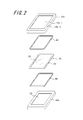
- FIG. 2 is an exploded perspective view showing a state in which the electronic apparatus 1 shown in FIG. 1 is disassembled into an upper casing 10a, a lower casing 10b, a touch panel assembly 30, an upper PET sheet 40, and a lower PET sheet 50.
- the touch panel assembly 30 is inserted between the upper casing 10a and the lower casing 10b, and the upper PET is interposed between the touch panel assembly 30 and the upper casing 10a and the lower casing 10b, respectively.
- the sheet 40 and the lower PET sheet 50 are inserted.
- the touch panel assembly 30 includes the touch panel 20, an elastic member 60, and a vibration part (not shown here) described later. Further, the elastic member 60 surrounds the entire surface of the touch panel 20 except for the upper surface area of the touch panel 20 corresponding to the opening 10a-1 of the upper housing 10a and the installation area of the vibration part.
- the upper casing 10a is provided with a flange 10a-2 extending inward over the entire circumference of the top, and the upper casing 10a covers the outer edge of the upper surface of the touch panel 20.
- the outer edge of the upper surface of the touch panel 20 refers to an edge area of the touch panel on the upper surface of the touch panel 20, and preferably refers to an area having a width of about 2 to 3 mm.
- the elastic member 60 on the outer edge of the upper surface of the touch panel 20 and the flange portion 10a-2 of the upper housing 10a are in close contact with each other via the frame-shaped upper PET sheet 40.
- the upper and lower surfaces of the upper PET sheet 40 may be fixed to the flange portion 10a-2 of the upper housing 10a and the elastic member 60 with, for example, a waterproof double-sided tape.
- the lower PET sheet 50 having a frame shape is also disposed between the elastic member 60 on the outer edge of the bottom surface of the touch panel 20 and the lower housing 10b.
- the bottom edge of the bottom surface of the touch panel 20 refers to a peripheral region of the touch panel on the bottom surface of the touch panel 20, and preferably refers to a region having a width of about 2 to 3 mm as in the case of the top edge of the top surface of the touch panel 20. It is more advantageous if the upper and lower surfaces of the lower PET sheet 50 are fixed to the elastic member 60 and the lower housing 10b, for example, with a waterproof double-sided tape.
- the upper PET sheet 40 and the lower PET sheet 50 described above are preferably used to adjust the position of the touch panel 20 in the vertical direction (the Z direction in FIG. 1), but are not necessarily required and will be omitted. Is also possible.
- a display unit 70 such as an LCD is disposed in the recess formed in the lower housing 10b.
- a substrate (not shown) is installed on the bottom surface of the display unit 70.
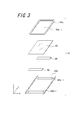
- FIG. 3 is an exploded perspective view showing a state in which the touch panel assembly 30 shown in FIG. 2 is disassembled into the touch panel 20, the vibration unit 80, the upper elastic member 60a, and the lower elastic member 60b.
- a vibrating unit 80 is disposed in the vicinity of the edge along the X direction in the figure.
- the vibration part 80 can be comprised with a piezoelectric element, for example.
- the arrangement of the vibration unit 80 is not limited to the vicinity of the edge along the X direction in the drawing of the touch panel 20, and can be arranged near the edge of the touch panel 20 along the Y direction in the drawing, for example.
- the vibration unit 80 presents a tactile sensation to the contact object that is in contact with the touch surface by generating vibration according to a predetermined vibration pattern.
- the vibration unit 80 induces vibration based on, for example, a drive signal supplied from a control unit (not shown).
- the upper elastic member 60a and the lower elastic member 60b constitute the elastic member 60 shown in FIG. 2 by sandwiching the touch panel 20 therebetween.
- the elastic member 60 is made of a material having sufficient waterproof and dustproof properties and appropriate elasticity, for example, a gel-like member such as silicon gel, or silicon rubber, among others.
- a gel-like member such as silicon gel, or silicon rubber, among others.
- the upper elastic member 60a has an opening 60a-1 corresponding to the opening 10a-1 of the upper housing 10a, while the lower elastic member 60b has an opening 60b-1 corresponding to the vibration part 80. Yes. Therefore, by sandwiching the touch panel 20 between the upper elastic member 60a and the lower elastic member 60b, the upper surface area of the touch panel 20 corresponding to the opening 10a-1 of the upper housing 10a and the installation area of the vibration unit 80 are excluded. The entire surface can be surrounded by the elastic member 60.
- the upper elastic member 60a and the lower elastic member 60b are integrated by, for example, being bonded to each other with an adhesive.
- the elastic member 60 has been described as a two-part structure of the upper elastic member 60a and the lower elastic member 60b. However, the elastic member 60 is not limited to this structure.
- the touch panel 20 may be fitted into the elastic member 60 while being deformed.
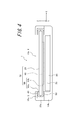
- FIG. 4 is a cross-sectional view taken along the line AA of the electronic device 1 in FIG.
- FIG. 4 reference numerals for explaining the configuration on the right side of the figure are omitted.
- the touch panel assembly 30 closely contacts the elastic member on the outer edge of the upper surface of the touch panel 20 and the flange portion 10a-2 of the upper housing 10a via the upper PET sheet 40,
- the elastic member at the outer edge of the bottom surface of the touch panel 20 and the lower housing 10b serving as a support member of the touch panel 20 are installed in the electronic apparatus 1 in a state of being in close contact with each other via the lower PET sheet 50.
- PET sheets 40 and 50 are not necessarily provided as described above, and the elastic member on the outer edge of the upper surface of the touch panel 20 and the flange portion 10a-2 of the upper housing 10a are in direct contact with each other, and the touch panel is provided.
- the elastic member on the outer edge of the bottom surface 20 and the lower housing 10b may be in direct contact with each other.
- either the elastic member on the outer edge of the upper surface of the touch panel 20 and the flange portion 10a-2 of the upper casing 10a, or the elastic member on the outer edge of the bottom surface of the touch panel 20 and the lower casing 10b may be brought into close contact with each other.
- the elastic member on the outer edge of the upper surface of the touch panel 20 and the flange portion 10a-2 of the upper housing 10a are brought into close contact with each other so that the upper surface outer edge of the touch panel 20 and the flange portion 10a-2 of the upper housing 10a are Intrusion of outside air into the inside of the apparatus can be blocked, that is, sealed by the upper elastic member 60a on the outer edge of the upper surface of the touch panel 20. Therefore, waterproofing and dustproofing for the electronic device 1 are realized.
- the bottom edge of the touch panel 20 and the lower casing 10b can be sealed. In this case, waterproofing and dustproofing for the electronic device 1 are realized.
- both the upper PET sheet 40 and the lower PET sheet 50 are not necessarily arranged continuously over the entire outer periphery of the upper surface and the outer periphery of the bottom surface of the touch panel 20.
- One of these may be arranged intermittently.
- an outside air blocking function is added between the upper surface outer edge of the touch panel 20 and the flange portion 10a-2 of the upper housing 10a.
- an outside air blocking function is added between the bottom surface outer edge of the touch panel 20 and the lower housing 10b.
- the touch panel 20 can bend and vibrate while deforming the elastic member 60. Little attenuation occurs.
- the touch panel 20 is curved and vibrated.
- peripheral components such as the display unit 70 due to external force applied during the operation
- the elastic member 60 can mitigate the impact caused by the contact. Therefore, the possibility that the touch panel 20 and peripheral components are damaged can be avoided.
- a gel-like member such as silicon gel or silicon rubber is used as the elastic member 60, a good buffer function can be obtained.
- the Go of the present invention naturally indicates the state shown in FIGS. 3 and 4, but when the touch panel 20 is vibrating in a curved manner, the touch panel 20 is displayed on the display unit 70. This includes a state in which the elastic member 60 is formed on the entire surface that may come into contact with peripheral components.
- the lower housing 10b corresponds to a support member.
- the support member is not limited to the lower housing 10b.
- a support portion that extends to the bottom surface of the touch panel 20 may be extended to the upper housing 10a, and this support portion may be used as the support member.
- the width of the recessed portion of the lower housing 10b and the display portion 70 can be expanded to use the display portion 70 as a support member, or the width of the recessed portion of the lower housing 10b and the substrate 90 can be expanded.
- the substrate 90 can be used as a support member.
- the upper elastic member 60a on the outer edge of the upper surface of the touch panel 20 and the collar portion 10a-2 of the upper housing 10a are described as being in close contact with each other.
- the upper housing 10a may be a two-part structure of a bezel (frame-like member) disposed above the outer edge of the upper surface of the touch panel 20 and the upper housing body, for example.
- the upper casing has such a two-part structure, the same effect as described above can be obtained by bringing the upper elastic member 60a on the outer edge of the upper surface of the touch panel 20 into close contact with the bezel.
- the elastic member that surrounds the entire surface of the touch panel, excluding the upper surface area of the touch panel corresponding to the opening of the upper housing and the installation area of the vibration part, While effectively suppressing the attenuation of the bending vibration of the touch panel by the vibration unit, it is possible to improve the waterproof and dustproof effect for the electronic device. And the collision with a touch panel and peripheral components which may arise when a touch panel curves can be relieved with the said elastic member.
- the present invention is not limited to the above embodiment, and many variations or modifications are possible.
- an aspect has been described in which an object is displayed on a display unit (not shown) arranged on the bottom surface of the touch panel and the touch panel detects an operator's contact.
- the present invention is not limited to such an embodiment.
- an embodiment in which an object is directly printed with ink or the like on the touch surface of the touch panel without having a display unit is also applicable. .
- the touch panel has been described assuming a member such as a so-called touch sensor.
- the touch panel used in the electronic device according to the present invention may be any as long as it can be touched by a contact object such as an operator's finger or a stylus pen.
- the touch panel used in the electronic device according to the present invention may be a member such as a simple “panel” that does not detect the position of contact of the contact object with the touch surface (that is, does not have a sensing function).
- the electronic device having such a configuration for example, it is possible to determine that contact with the touch panel has been made based on the pressure detected by the pressure detection unit by further providing a pressure detection unit that detects pressure on the touch panel. it can.
- a touch panel is used to detect contact with the touch surface of the touch panel.
- the touch detection unit detects a press on the touch panel and that the touch is made on the touch panel based on the press.
- the above-described press detection unit detects a press on the touch surface of the touch panel.
- a strain gauge sensor or a piezoelectric that changes physical or electrical characteristics (strain, resistance, voltage, etc.) according to the press.
- An arbitrary number of elements can be used.
- the vibration unit is a piezoelectric element
- the piezoelectric element can also be used as a press detection unit.
- the piezoelectric element of the pressure detection unit is a load (force) magnitude (or magnitude of the load (force) related to the pressure on the touch surface of the touch panel.
- the voltage magnitude (voltage value) which is an electrical characteristic, changes according to the speed (acceleration) at which the voltage changes.
- the pressure detection unit can notify the control unit of the magnitude of the voltage (voltage value (hereinafter simply referred to as data)).
- the control unit acquires the data when the press detection unit notifies the control unit of the data, or when the control unit detects data related to the piezoelectric element of the press detection unit.
- a control part acquires the data based on the press with respect to the touch surface of a touchscreen. That is, a control part acquires the data based on a press from a press detection part. Then, when the data based on the press satisfies a predetermined standard, the control unit can determine that contact has been made and generate a predetermined vibration.
- the predetermined reference can be set as appropriate according to the load characteristic when the push button switch is to be expressed.
- such a pressure detection unit can be configured according to a contact detection method on the touch panel.
- a strain gauge sensor, a piezoelectric element, or the like is used by associating the magnitude of the resistance corresponding to the size of the contact area with the pressing load (force) on the touch surface of the touch panel. It can be configured without.
- the capacitance can be configured without using a strain gauge sensor or a piezoelectric element by associating the size of the capacitance with a load (force) of pressing against the touch surface of the touch panel. it can.
- Such a pressure detection unit can assume various configurations according to a contact detection method on the touch panel.
- a strain gauge sensor, a piezoelectric element, or the like is used by associating the magnitude of the resistance corresponding to the size of the contact area with the pressing load (force) on the touch surface of the touch panel. It can be configured without.
- the capacitance can be configured without using a strain gauge sensor or a piezoelectric element by associating the size of the capacitance with a load (force) of pressing against the touch surface of the touch panel. it can.
- the vibration unit is configured by using an arbitrary number of piezoelectric vibrators, is configured by providing a transparent piezoelectric element on the entire surface of the touch panel, or configured to rotate the eccentric motor once in one cycle of the drive signal. You can also do it.
- the pressure detection unit and the vibration unit are configured using a piezoelectric element
- the pressure detection unit and the vibration unit may be configured by sharing the piezoelectric element. This is because the piezoelectric element generates a voltage when pressure is applied and deforms when the voltage is applied.
- the vibration unit drives the piezoelectric element to generate vibration. It can also be generated.
- the voltage value (data) may reach a predetermined reference value, It may be when the value (data) exceeds a predetermined reference value or when a voltage value (data) equal to the predetermined reference value is detected.
- the electronic apparatus according to the present invention does not necessarily have such a configuration, and the touch panel and the display unit can be separated from each other.
- the configuration in which the touch panel is arranged so as to overlap the upper surface of the display unit allows the operator to easily recognize the correspondence between the displayed image, the region where the operation input is detected, and the generated vibration. Can do.
- the display unit and the touch panel in the description of the above-described embodiment may be configured by an integrated device by providing both functions of the display unit and the contact detection unit on a common substrate.
- a plurality of photoelectric conversion elements such as photodiodes are regularly arranged in a matrix electrode array of pixel electrodes included in the liquid crystal panel.
- This device displays an image with a liquid crystal panel structure, while reflecting the light of a backlight for liquid crystal display at the tip of a pen that touches and inputs a desired position on the surface of the panel. The reflected light is reflected by peripheral photoelectric conversion elements.
- the touch position can be detected by receiving the light.
- the vibration unit may be configured to vibrate the touch panel indirectly by vibrating the electronic device based on a vibration motor (eccentric motor) or by arranging a piezoelectric element on the touch panel.
- the touch panel may be configured to vibrate directly. In the case of such a configuration that is indirectly vibrated, when the entire surface of the touch panel according to the present invention is surrounded by the elastic member, the installation area of the vibration part is not removed.
- the cellular phone described below is an example of an electronic device to which the present invention can be applied, and is not limited to the configuration shown in the drawing.
- the configuration of the mobile phone 100 can be appropriately changed within a range that does not hinder the application of the present invention.
- a mobile phone as another electronic device to which the present invention can be applied includes a lower casing 110b that houses a substrate 190 and a display portion 170, a lower casing 110b, and a waterproof packing or bonding member ( And an upper housing 110a fixed via a not-shown).
- the upper casing 110a has a panel 120 provided with a piezoelectric element portion 180 therein.
- the panel 120 is held between the upper casing ridge 110a-2 and the upper surface of the lower casing 110b by the upper and lower elastic members 160a and 160b and the PET sheets 140 and 150 disposed outside the elastic members. Has been.
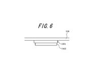
- the piezoelectric element unit 180 includes a piezoelectric element 1802 and a bonding member 1801 for bonding the piezoelectric element to the panel 120.
- Panel 120 and piezoelectric element 1802 are each substantially rectangular.
- the contact area of the piezoelectric element 1802 with the bonding member 1801 in the piezoelectric element unit 180 may be substantially the entire surface of one side of the piezoelectric element 1802.
- the vibration in the piezoelectric element 1802 is efficiently transmitted to the panel 120 and the panel 120 is brought into contact with the human body as compared with the case where only the both ends of the piezoelectric element are used as the contact region with the bonding member in the piezoelectric element.
- the panel 120 can be curved and vibrated with sufficient strength so as not to be attenuated.
- the display unit 70 is disposed approximately at the center of the panel 120 in the short direction.
- the piezoelectric element 1802 is arranged at a predetermined distance from the end portion of the panel 120 in the longitudinal direction, and is arranged in the vicinity of the end portion so that the longitudinal direction of the piezoelectric element 1802 is along the short side of the panel 120.
- the display unit 70 and the piezoelectric element unit 180 may be arranged side by side in a direction parallel to the inner surface of the panel 120. For example, when the configuration is such that the panel 120 and the display unit 70 do not overlap, the piezoelectric element unit 180 may be disposed in the center of the panel 120.
- the piezoelectric element portion 180 When the piezoelectric element portion 180 is disposed at the center of the panel 120, the vibration of the piezoelectric element 1802 is evenly transmitted to the entire panel 120, and even when the user touches the ear to various positions of the panel 120, the voice is recognized. can do. Similar to the above-described embodiment, a plurality of piezoelectric elements may be mounted.
- the panel 120 detects contact of a finger, a pen, a stylus pen, or the like with respect to the touch panel.
- the touch panel detection method may be any method such as a capacitance method, a resistance film method, a surface acoustic wave method (or an ultrasonic method), an infrared method, an electromagnetic induction method, and a load detection method.
- the panel 120 may be a protective panel for protecting the display unit 70.
- the material of the panel 120 is made of, for example, glass or synthetic resin, and may be a plate-like body.
- the display unit 70 is a display device such as a liquid crystal display, an organic EL display, or an inorganic EL display.
- the piezoelectric element 1802 of the piezoelectric element unit 180 is an element that expands and contracts according to the electromechanical coupling coefficient of the constituent material by applying a voltage.
- the piezoelectric element 1802 may be a unimorph, bimorph, or multilayer piezoelectric element.
- the stacked piezoelectric element includes a stacked bimorph element in which bimorphs are stacked (for example, 16 layers or 24 layers are stacked).
- a laminated piezoelectric element it is composed of a laminated structure of a plurality of dielectric layers made of, for example, PZT (lead zirconate titanate) and electrode layers arranged between the dielectric layers.
- the bonding member 1801 of the piezoelectric element unit 180 is an adhesive having a thermosetting property or an ultraviolet curable property, a double-sided tape, or the like.
- an optical elastic resin which is a colorless and transparent acrylic ultraviolet curable adhesive may be used.
- the panel 120 is fixed to the elastic members 160a and 160b of the casing 110 over the entire circumference thereof, so that dust or water can be prevented from entering the mobile phone and vibration of the panel 120 can be reduced. Can be reduced.
- the mobile phone having the above configuration can transmit sound to the user even if a part of the user's body comes into contact with the panel 120 that vibrates due to expansion and contraction of the piezoelectric element portion 180.
- the piezoelectric element unit 180 expands and contracts (curves) in the longitudinal direction based on, for example, an electrical signal output from a control unit (not shown). Since the piezoelectric element 1802 is attached to the panel 120 by the bonding member 1801, the panel 120 vibrates as the piezoelectric element unit 180 expands and contracts. The panel 120 vibrates not only in the attachment region to which the piezoelectric element 1802 is attached, but also in a region away from the attachment region. At a certain moment, the panel 120 vibrates in such a manner that a portion having a relatively large vibration amplitude and a portion having a relatively small vibration amplitude are randomly distributed throughout the panel. That is, vibrations of a plurality of waves are detected over the entire panel.
- the above mobile phone generates a vibration in a panel such as a cover panel that protects the touch panel or the display unit by applying a predetermined electrical signal (audio signal) to the piezoelectric element, and a user is applied to the panel that has been vibrated.
- a sound can be transmitted to the user by contacting a part of the body (eg, cartilage of the outer ear).
- the output sound from the panel of the above mobile phone is the voice of the other party, the incoming melody or music including music.
- the music may be played based on music data stored in an internal memory, or music data stored in an external server or the like may be played back via a network.
- the amplifier may be controlled to amplify only the low sound range.
- a dynamic speaker may be provided separately.
- the sound outlet of the dynamic speaker may be closed by a waterproof sheet that allows gas to pass but not liquid, such as Gore-Tex (trademark).
- Piezoelectric element vibrates not only the attachment area of the panel where the piezoelectric element is attached, but also the area away from the attachment area of the panel. Therefore, the user can hear the sound by touching the ear to an arbitrary position on the panel.
- the user can connect an electronic device including a panel having a panel approximately the same size as the user's ear or larger than the user's ear. By making contact so that the entirety is covered, it is possible to hear the sound output from the electronic device while reducing ambient sound (noise) from entering the ear canal.
- the panel may oscillate in a region wider than a region having a length corresponding to the distance from the earring to the tragus and the antitragus and a width corresponding to the distance from the earring leg to the antitragus.
- the average ear size can be found, for example, by referring to the Japanese human body size database (1992-1994) created by the Human Life Engineering Research Center (HQL). In general, if a panel is made with the size of Japanese ears as a guide, it can be applied to foreigners.
- the above mobile phone can transmit sound to the user by vibration through a part of the user's body (for example, cartilage of the outer ear). There are few transmitted sounds. Therefore, it is suitable for listening to a recorded message on a train or the like.
- the above mobile phone transmits sound by vibration of the panel 120, even if the user wears an earphone or a headphone, for example, the user can touch the electronic device to the earphone or the headphone and the body. You can hear the sound through some of the.
- the display unit 70 and the piezoelectric element unit 180 may be arranged side by side in a direction parallel to the inner surface of the panel 120.
- the display unit 70 may be attached to the panel 120, which increases the rigidity of the lower part of the panel 120, and the vibration of the upper part of the panel 120 to which the piezoelectric element part 180 is attached is compared with the lower part of the panel 120.
- it can be vibrated greatly. Therefore, it is possible to efficiently transmit the vibration of the panel 120 to the user.
- the voltage applied to the piezoelectric element is higher than the voltage applied to the piezoelectric element mounted on a normal so-called panel speaker. Should be set higher.
- the support structure for the panel housing is greatly different.
- the panel speaker disclosed in Japanese Patent Publication No. 2010-1114866, the panel itself is not greatly deformed, and the entire panel is moved in parallel in the thickness direction of the panel. It is supported on the housing at both ends in the direction by a film-like member, a stretchable rubber member, a spring member, or the like.
- the above mobile phone has a structure in which the entire outer periphery of the panel 120 is supported by the casing 110 by the elastic member 160 and the PET sheet. That is, the panel 120 of the mobile phone 100 is firmly fixed to the housing as compared with the panel speaker panel described in the above document. Therefore, the voltage applied to the piezoelectric element unit 180 of the mobile phone 100 is higher than the voltage applied to the piezoelectric element mounted on a normal so-called panel speaker.
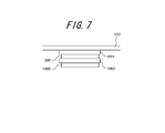
- FIG. 7 is a partial sectional view showing a modification of another electronic apparatus to which the present invention can be applied.
- an intermediate member 200 may be disposed between the piezoelectric element unit 180 and the panel 120.
- the piezoelectric element portion 180 and the intermediate member 200 may be bonded by the bonding member 1801
- the intermediate member 200 and the panel 120 may be bonded by the bonding member 1801.
- the joining member 1801 may be the above-described various adhesives or double-sided tape.
- the intermediate member 200 is a resin plate including, for example, a resin plate, sheet metal, or glass fiber.
- the piezoelectric element is affixed to the panel, but may be attached to a location different from the panel.
- the piezoelectric element may be attached to a battery lid that is attached to the housing and covers the battery. Since the battery lid is often attached to a surface different from the panel in the mobile phone, according to such a configuration, the user listens to the sound by touching a part of the body (for example, an ear) to a surface different from the panel. Can do.
- Electronic devices that transmit sound to the user through a part of the user's body are conducted through the part of the user's body that contacts the vibrating panel. It is also possible to transmit to the user both the sound to be heard (human body conduction sound) and the vibration of the air in the vicinity of the panel (air conduction sound) caused by the vibration of the panel.
Landscapes
- Engineering & Computer Science (AREA)
- General Engineering & Computer Science (AREA)
- Theoretical Computer Science (AREA)
- Human Computer Interaction (AREA)
- Physics & Mathematics (AREA)
- General Physics & Mathematics (AREA)
- Computer Hardware Design (AREA)
- Telephone Set Structure (AREA)
- Position Input By Displaying (AREA)
Abstract
Description
10a、110a 上部筐体
10b、110b 下部筐体
10a-1、110a-1 上部筐体の開口部
10a-2、110a-2 庇部
20、120 タッチパネル
30,130 タッチパネルアセンブリ
40,140 上側PET部材
50,150 下側PET部材
60,160 弾性部材
60a、160a 上部弾性部材
60a-1 上部弾性部材の開口部
60b、160b 下部弾性部材
60b-1 下部弾性部材の開口部
70,170 表示部
80、180 振動部、圧電素子部
1801 接合部材
1802 圧電素子
90,190 基板
200 中間部材
Claims (2)
- パネルと、
該パネルを振動させる振動部と、
該パネルの上面外縁を覆う上部筐体と
を備えた電子機器であって、
上記上部筐体の頂部全周にわたり内側に延在させた庇部を有し、
上記上部筐体の開口部に対応する上記タッチパネルの上面領域および上記振動部の設置領域を除く、上記タッチパネルの全面を弾性部材で囲繞すると共に、
上記タッチパネルの上面外縁の上記弾性部材と上記庇部、および上記タッチパネルの底面外縁の上記弾性部材と上記タッチパネルの支持部材の少なくともいずれか一方を密接させた
ことを特徴とする電子機器。 - 前記パネルは、利用者の耳全体を覆うことができる大きさである
請求項1に記載の電子機器。
Priority Applications (2)
| Application Number | Priority Date | Filing Date | Title |
|---|---|---|---|
| US14/001,490 US9753536B2 (en) | 2011-02-24 | 2012-02-24 | Electronic device |
| JP2013500912A JP5687331B2 (ja) | 2011-02-24 | 2012-02-24 | 防水型電子機器 |
Applications Claiming Priority (2)
| Application Number | Priority Date | Filing Date | Title |
|---|---|---|---|
| JP2011039049 | 2011-02-24 | ||
| JP2011-039049 | 2011-02-24 |
Publications (1)
| Publication Number | Publication Date |
|---|---|
| WO2012114772A1 true WO2012114772A1 (ja) | 2012-08-30 |
Family
ID=46720562
Family Applications (1)
| Application Number | Title | Priority Date | Filing Date |
|---|---|---|---|
| PCT/JP2012/001296 Ceased WO2012114772A1 (ja) | 2011-02-24 | 2012-02-24 | 電子機器 |
Country Status (3)
| Country | Link |
|---|---|
| US (1) | US9753536B2 (ja) |
| JP (2) | JP2012190452A (ja) |
| WO (1) | WO2012114772A1 (ja) |
Cited By (22)
| Publication number | Priority date | Publication date | Assignee | Title |
|---|---|---|---|---|
| WO2014057594A1 (ja) * | 2012-10-09 | 2014-04-17 | パナソニック株式会社 | 電子機器 |
| JP2014146269A (ja) * | 2013-01-30 | 2014-08-14 | Kyocera Corp | 入力装置、および電子機器 |
| JP2014164429A (ja) * | 2013-02-22 | 2014-09-08 | Kyocera Corp | 振動装置、電子機器、および携帯端末 |
| JP2014186653A (ja) * | 2013-03-25 | 2014-10-02 | Kyocera Corp | 入力装置および電子機器 |
| JP2014241607A (ja) * | 2014-07-28 | 2014-12-25 | 京セラ株式会社 | 電子機器 |
| JP2015061285A (ja) * | 2013-09-20 | 2015-03-30 | 株式会社ファインウェル | 送受話装置および送受話方法 |
| WO2016131265A1 (zh) * | 2015-08-24 | 2016-08-25 | 中兴通讯股份有限公司 | 具有触摸屏的电子产品 |
| JP2018502486A (ja) * | 2014-11-25 | 2018-01-25 | モダ−イノチップス シーオー エルティディー | 端末の制御装置及びこれを用いた端末の制御方法 |
| US9980024B2 (en) | 2011-02-25 | 2018-05-22 | Rohm Co., Ltd. | Hearing system and finger ring for the hearing system |
| US10013862B2 (en) | 2014-08-20 | 2018-07-03 | Rohm Co., Ltd. | Watching system, watching detection device, and watching notification device |
| US10075574B2 (en) | 2013-08-23 | 2018-09-11 | Rohm Co., Ltd. | Mobile telephone |
| US10079925B2 (en) | 2012-01-20 | 2018-09-18 | Rohm Co., Ltd. | Mobile telephone |
| US10103766B2 (en) | 2013-10-24 | 2018-10-16 | Rohm Co., Ltd. | Wristband-type handset and wristband-type alerting device |
| US10158947B2 (en) | 2012-01-20 | 2018-12-18 | Rohm Co., Ltd. | Mobile telephone utilizing cartilage conduction |
| JP2019067445A (ja) * | 2018-12-25 | 2019-04-25 | 株式会社半導体エネルギー研究所 | 情報処理装置 |
| US10356231B2 (en) | 2014-12-18 | 2019-07-16 | Finewell Co., Ltd. | Cartilage conduction hearing device using an electromagnetic vibration unit, and electromagnetic vibration unit |
| CN110930876A (zh) * | 2018-09-20 | 2020-03-27 | 乐金显示有限公司 | 显示设备和包括该显示设备的计算设备 |
| US10779075B2 (en) | 2010-12-27 | 2020-09-15 | Finewell Co., Ltd. | Incoming/outgoing-talk unit and incoming-talk unit |
| US10778824B2 (en) | 2016-01-19 | 2020-09-15 | Finewell Co., Ltd. | Pen-type handset |
| US10795321B2 (en) | 2015-09-16 | 2020-10-06 | Finewell Co., Ltd. | Wrist watch with hearing function |
| US10967521B2 (en) | 2015-07-15 | 2021-04-06 | Finewell Co., Ltd. | Robot and robot system |
| US11526033B2 (en) | 2018-09-28 | 2022-12-13 | Finewell Co., Ltd. | Hearing device |
Families Citing this family (12)
| Publication number | Priority date | Publication date | Assignee | Title |
|---|---|---|---|---|
| WO2013099743A1 (ja) * | 2011-12-27 | 2013-07-04 | 株式会社村田製作所 | 触覚提示装置 |
| KR102496410B1 (ko) * | 2016-03-25 | 2023-02-06 | 삼성전자 주식회사 | 전자 장치 및 전자 장치의 소리 출력 방법 |
| KR20170114471A (ko) * | 2016-04-05 | 2017-10-16 | 엘지디스플레이 주식회사 | 유기발광 표시 장치 |
| DE102017107366A1 (de) * | 2016-07-18 | 2018-01-18 | Preh Gmbh | Bedienvorrichtung mit aktiver haptischer Feedbackerzeugung und Schwingungsdämpfer |
| US20190286238A1 (en) * | 2016-10-27 | 2019-09-19 | Nidec Sankyo Corporation | Touch panel-equipped display device |
| JP6657058B2 (ja) * | 2016-11-28 | 2020-03-04 | ミネベアミツミ株式会社 | 電子機器 |
| CN109961627A (zh) * | 2017-12-26 | 2019-07-02 | 鸿富锦精密工业(深圳)有限公司 | 电子装置 |
| US11675438B2 (en) * | 2019-02-28 | 2023-06-13 | Samsung Display Co., Ltd. | Display device and sound providing method of the display device |
| JP7067530B2 (ja) * | 2019-05-24 | 2022-05-16 | 株式会社村田製作所 | 振動装置 |
| KR102104623B1 (ko) * | 2019-08-08 | 2020-04-24 | 한화시스템 주식회사 | 터치스크린 장치 및 이의 조립방법 |
| JP7286255B2 (ja) * | 2019-12-10 | 2023-06-05 | アルパイン株式会社 | 表示装置 |
| JP2023094508A (ja) * | 2021-12-23 | 2023-07-05 | パナソニックIpマネジメント株式会社 | 表示装置及び入力装置 |
Citations (1)
| Publication number | Priority date | Publication date | Assignee | Title |
|---|---|---|---|---|
| JP2002149312A (ja) * | 2000-08-08 | 2002-05-24 | Ntt Docomo Inc | 携帯型電子機器、電子機器、振動発生器、振動による報知方法および報知制御方法 |
Family Cites Families (15)
| Publication number | Priority date | Publication date | Assignee | Title |
|---|---|---|---|---|
| SK20292000A3 (sk) * | 1998-07-03 | 2001-06-11 | New Transducers Limited | Rezonančný panelový reproduktor |
| JP2010044497A (ja) | 2008-08-11 | 2010-02-25 | Sumitomo Wiring Syst Ltd | パネル固定用フレーム及びディスプレイ装置 |
| JP2010114866A (ja) | 2008-11-07 | 2010-05-20 | Authentic Ltd | パネル型スピーカ |
| US20100225600A1 (en) * | 2009-03-09 | 2010-09-09 | Motorola Inc. | Display Structure with Direct Piezoelectric Actuation |
| US20100245254A1 (en) * | 2009-03-24 | 2010-09-30 | Immersion Corporation | Planar Suspension Of A Haptic Touch Screen |
| KR101066941B1 (ko) * | 2009-06-16 | 2011-09-26 | 삼성전기주식회사 | 터치 입력식 전자기기 |
| KR20110023032A (ko) * | 2009-08-28 | 2011-03-08 | 삼성전기주식회사 | 터치스크린장치 |
| US8816981B2 (en) * | 2009-08-31 | 2014-08-26 | Nissha Printing Co., Ltd. | Mount structure of touch panel with vibration function |
| JP4811965B2 (ja) * | 2009-11-02 | 2011-11-09 | Smk株式会社 | タッチパネルの保持構造 |
| EP2325733B1 (en) * | 2009-11-02 | 2013-06-12 | SMK Corporation | Holding structure for a touch panel |
| WO2012114761A1 (ja) * | 2011-02-23 | 2012-08-30 | 京セラ株式会社 | 電子機器 |
| WO2012114754A1 (ja) * | 2011-02-24 | 2012-08-30 | 京セラ株式会社 | 電子機器 |
| WO2012118474A1 (en) * | 2011-02-28 | 2012-09-07 | Hewlett-Packard Development Company L.P. | Hermetic seal |
| KR101278405B1 (ko) * | 2011-03-23 | 2013-06-24 | 삼성전기주식회사 | 압전 진동 모듈 및 이를 채용한 터치스크린 |
| US9317122B2 (en) * | 2011-08-19 | 2016-04-19 | Kyocera Corporation | Electronic device |
-
2012
- 2012-02-24 JP JP2012038832A patent/JP2012190452A/ja active Pending
- 2012-02-24 US US14/001,490 patent/US9753536B2/en not_active Expired - Fee Related
- 2012-02-24 WO PCT/JP2012/001296 patent/WO2012114772A1/ja not_active Ceased
- 2012-02-24 JP JP2013500912A patent/JP5687331B2/ja not_active Expired - Fee Related
Patent Citations (1)
| Publication number | Priority date | Publication date | Assignee | Title |
|---|---|---|---|---|
| JP2002149312A (ja) * | 2000-08-08 | 2002-05-24 | Ntt Docomo Inc | 携帯型電子機器、電子機器、振動発生器、振動による報知方法および報知制御方法 |
Cited By (36)
| Publication number | Priority date | Publication date | Assignee | Title |
|---|---|---|---|---|
| US10779075B2 (en) | 2010-12-27 | 2020-09-15 | Finewell Co., Ltd. | Incoming/outgoing-talk unit and incoming-talk unit |
| US9980024B2 (en) | 2011-02-25 | 2018-05-22 | Rohm Co., Ltd. | Hearing system and finger ring for the hearing system |
| US10158947B2 (en) | 2012-01-20 | 2018-12-18 | Rohm Co., Ltd. | Mobile telephone utilizing cartilage conduction |
| US10079925B2 (en) | 2012-01-20 | 2018-09-18 | Rohm Co., Ltd. | Mobile telephone |
| US10778823B2 (en) | 2012-01-20 | 2020-09-15 | Finewell Co., Ltd. | Mobile telephone and cartilage-conduction vibration source device |
| US10506343B2 (en) | 2012-06-29 | 2019-12-10 | Finewell Co., Ltd. | Earphone having vibration conductor which conducts vibration, and stereo earphone including the same |
| US10834506B2 (en) | 2012-06-29 | 2020-11-10 | Finewell Co., Ltd. | Stereo earphone |
| JPWO2014057594A1 (ja) * | 2012-10-09 | 2016-08-25 | パナソニックIpマネジメント株式会社 | 電子機器 |
| WO2014057594A1 (ja) * | 2012-10-09 | 2014-04-17 | パナソニック株式会社 | 電子機器 |
| US20150009176A1 (en) * | 2012-10-09 | 2015-01-08 | Panasonic Corporation | Electronic device |
| CN104040471A (zh) * | 2012-10-09 | 2014-09-10 | 松下电器产业株式会社 | 电子设备 |
| JP2014146269A (ja) * | 2013-01-30 | 2014-08-14 | Kyocera Corp | 入力装置、および電子機器 |
| JP2014164429A (ja) * | 2013-02-22 | 2014-09-08 | Kyocera Corp | 振動装置、電子機器、および携帯端末 |
| JP2014186653A (ja) * | 2013-03-25 | 2014-10-02 | Kyocera Corp | 入力装置および電子機器 |
| US10075574B2 (en) | 2013-08-23 | 2018-09-11 | Rohm Co., Ltd. | Mobile telephone |
| US10237382B2 (en) | 2013-08-23 | 2019-03-19 | Finewell Co., Ltd. | Mobile telephone |
| JP2015061285A (ja) * | 2013-09-20 | 2015-03-30 | 株式会社ファインウェル | 送受話装置および送受話方法 |
| US10103766B2 (en) | 2013-10-24 | 2018-10-16 | Rohm Co., Ltd. | Wristband-type handset and wristband-type alerting device |
| JP2014241607A (ja) * | 2014-07-28 | 2014-12-25 | 京セラ株式会社 | 電子機器 |
| US10013862B2 (en) | 2014-08-20 | 2018-07-03 | Rohm Co., Ltd. | Watching system, watching detection device, and watching notification device |
| US10380864B2 (en) | 2014-08-20 | 2019-08-13 | Finewell Co., Ltd. | Watching system, watching detection device, and watching notification device |
| US10250736B2 (en) | 2014-11-25 | 2019-04-02 | Moda-Innochips Co., Ltd. | Terminal controlling device and controlling method using same |
| JP2018502486A (ja) * | 2014-11-25 | 2018-01-25 | モダ−イノチップス シーオー エルティディー | 端末の制御装置及びこれを用いた端末の制御方法 |
| US10356231B2 (en) | 2014-12-18 | 2019-07-16 | Finewell Co., Ltd. | Cartilage conduction hearing device using an electromagnetic vibration unit, and electromagnetic vibration unit |
| US11601538B2 (en) | 2014-12-18 | 2023-03-07 | Finewell Co., Ltd. | Headset having right- and left-ear sound output units with through-holes formed therein |
| US10848607B2 (en) | 2014-12-18 | 2020-11-24 | Finewell Co., Ltd. | Cycling hearing device and bicycle system |
| US10967521B2 (en) | 2015-07-15 | 2021-04-06 | Finewell Co., Ltd. | Robot and robot system |
| WO2016131265A1 (zh) * | 2015-08-24 | 2016-08-25 | 中兴通讯股份有限公司 | 具有触摸屏的电子产品 |
| US10795321B2 (en) | 2015-09-16 | 2020-10-06 | Finewell Co., Ltd. | Wrist watch with hearing function |
| US10778824B2 (en) | 2016-01-19 | 2020-09-15 | Finewell Co., Ltd. | Pen-type handset |
| CN110930876A (zh) * | 2018-09-20 | 2020-03-27 | 乐金显示有限公司 | 显示设备和包括该显示设备的计算设备 |
| US11223896B2 (en) | 2018-09-20 | 2022-01-11 | Lg Display Co., Ltd. | Display apparatus and computing apparatus including the same |
| US11665467B2 (en) | 2018-09-20 | 2023-05-30 | Lg Display Co., Ltd. | Display apparatus and computing apparatus including the same |
| US12028676B2 (en) | 2018-09-20 | 2024-07-02 | Lg Display Co., Ltd. | Vibration apparatus |
| US11526033B2 (en) | 2018-09-28 | 2022-12-13 | Finewell Co., Ltd. | Hearing device |
| JP2019067445A (ja) * | 2018-12-25 | 2019-04-25 | 株式会社半導体エネルギー研究所 | 情報処理装置 |
Also Published As
| Publication number | Publication date |
|---|---|
| JP5687331B2 (ja) | 2015-03-18 |
| JP2012190452A (ja) | 2012-10-04 |
| JPWO2012114772A1 (ja) | 2014-07-07 |
| US20130335210A1 (en) | 2013-12-19 |
| US9753536B2 (en) | 2017-09-05 |
Similar Documents
| Publication | Publication Date | Title |
|---|---|---|
| JP5687331B2 (ja) | 防水型電子機器 | |
| JP5654665B2 (ja) | 電子機器 | |
| JP5635633B2 (ja) | 電子機器 | |
| WO2012114750A1 (ja) | 電子機器 | |
| JP5855508B2 (ja) | 電子機器 | |
| JPWO2012117738A1 (ja) | 電子機器及び電子機器の製造方法 | |
| JP5563106B2 (ja) | 電子機器 | |
| WO2012114763A1 (ja) | 電子機器 | |
| JPWO2012111352A1 (ja) | 電子機器 | |
| JP6073071B2 (ja) | 電子機器 | |
| WO2014020877A1 (ja) | 電子機器 | |
| WO2012137442A1 (ja) | 電子機器 | |
| WO2012137443A1 (ja) | 電子機器 | |
| WO2012137440A1 (ja) | 電子機器 | |
| WO2012111351A1 (ja) | 電子機器 | |
| JP5816130B2 (ja) | パネル装置 | |
| JP2013242814A (ja) | 電子機器 | |
| JP2014027619A (ja) | 電子機器 | |
| JP2014027621A (ja) | 電子機器 |
Legal Events
| Date | Code | Title | Description |
|---|---|---|---|
| 121 | Ep: the epo has been informed by wipo that ep was designated in this application |
Ref document number: 12750209 Country of ref document: EP Kind code of ref document: A1 |
|
| ENP | Entry into the national phase |
Ref document number: 2013500912 Country of ref document: JP Kind code of ref document: A |
|
| WWE | Wipo information: entry into national phase |
Ref document number: 14001490 Country of ref document: US |
|
| NENP | Non-entry into the national phase |
Ref country code: DE |
|
| 122 | Ep: pct application non-entry in european phase |
Ref document number: 12750209 Country of ref document: EP Kind code of ref document: A1 |