WO2012114741A1 - ドラム式洗濯機 - Google Patents
ドラム式洗濯機 Download PDFInfo
- Publication number
- WO2012114741A1 WO2012114741A1 PCT/JP2012/001204 JP2012001204W WO2012114741A1 WO 2012114741 A1 WO2012114741 A1 WO 2012114741A1 JP 2012001204 W JP2012001204 W JP 2012001204W WO 2012114741 A1 WO2012114741 A1 WO 2012114741A1
- Authority
- WO
- WIPO (PCT)
- Prior art keywords
- drum
- baffles
- washing machine
- rotating drum
- type washing
- Prior art date
- Legal status (The legal status is an assumption and is not a legal conclusion. Google has not performed a legal analysis and makes no representation as to the accuracy of the status listed.)
- Ceased
Links
Images

Classifications
-
- D—TEXTILES; PAPER
- D06—TREATMENT OF TEXTILES OR THE LIKE; LAUNDERING; FLEXIBLE MATERIALS NOT OTHERWISE PROVIDED FOR
- D06F—LAUNDERING, DRYING, IRONING, PRESSING OR FOLDING TEXTILE ARTICLES
- D06F23/00—Washing machines with receptacles, e.g. perforated, having a rotary movement, e.g. oscillatory movement, the receptacle serving both for washing and for centrifugally separating water from the laundry
- D06F23/02—Washing machines with receptacles, e.g. perforated, having a rotary movement, e.g. oscillatory movement, the receptacle serving both for washing and for centrifugally separating water from the laundry and rotating or oscillating about a horizontal axis
-
- D—TEXTILES; PAPER
- D06—TREATMENT OF TEXTILES OR THE LIKE; LAUNDERING; FLEXIBLE MATERIALS NOT OTHERWISE PROVIDED FOR
- D06F—LAUNDERING, DRYING, IRONING, PRESSING OR FOLDING TEXTILE ARTICLES
- D06F23/00—Washing machines with receptacles, e.g. perforated, having a rotary movement, e.g. oscillatory movement, the receptacle serving both for washing and for centrifugally separating water from the laundry
- D06F23/06—Washing machines with receptacles, e.g. perforated, having a rotary movement, e.g. oscillatory movement, the receptacle serving both for washing and for centrifugally separating water from the laundry and rotating or oscillating about an inclined axis
-
- D—TEXTILES; PAPER
- D06—TREATMENT OF TEXTILES OR THE LIKE; LAUNDERING; FLEXIBLE MATERIALS NOT OTHERWISE PROVIDED FOR
- D06F—LAUNDERING, DRYING, IRONING, PRESSING OR FOLDING TEXTILE ARTICLES
- D06F37/00—Details specific to washing machines covered by groups D06F21/00 - D06F25/00
- D06F37/02—Rotary receptacles, e.g. drums
- D06F37/04—Rotary receptacles, e.g. drums adapted for rotation or oscillation about a horizontal or inclined axis
- D06F37/06—Ribs, lifters, or rubbing means forming part of the receptacle
Definitions
- the present invention relates to a drum-type washing machine for washing laundry in a rotating drum.
- FIG. 3 shows a cross-sectional view of a conventional drum-type washing machine described in Patent Document 1. As shown in FIG.
- a water tank 2 supported by a plurality of suspensions (not shown) is disposed in a housing 1.
- the water tank 2 has a substantially cylindrical shape that is axially symmetrical around the rotation axis.
- the rotation axis of the water tank 2 is inclined forward with respect to the horizontal direction so that the bottom 4a side of the water tank 2 is lower than the opening 2a on the front side of the water tank 2.
- the drum 4 which has many holes 3 in the surrounding wall is arrange
- the drum 4 is rotationally driven by a drive device 5 such as a motor provided on the bottom of the water tank 2.
- the drum 4 rotates in both forward and reverse directions (forward and reverse rotation).
- the clothes A in the drum 4 are lifted by the baffles 6 provided on the peripheral wall in the drum 4 and fall. Thereby, the clothes A are agitated.
- the baffle 6 extends from the bottom portion 4 a in the drum 4 toward the opening 2 a and protrudes inward in the rotational axis direction of the drum 4.
- the size of the baffle 6 is larger on the bottom surface 4 a side than on the opening 2 a side.
- the drum 4 has a tapered structure in which the diameter of the front surface portion is larger than the diameter of the bottom surface portion (i.e., the tapered structure with the larger diameter on the front surface side).
- An auxiliary baffle 21 is provided on the bottom 4 a of the drum 4.
- the auxiliary baffle 21 is connected to both side surfaces 6 a of the baffle 6 to form an inclined surface 21 a that expands toward the bottom surface 4 a of the drum 4.
- the auxiliary baffle 21 enables the laundry to be moved to the front side of the drum 4.
- the drum 4 has a tapered structure with a large diameter on the front side, so when the drum 4 rotates, the laundry tends to move to the front side of the drum 4.
- the peripheral speed of the drum is fast, so the laundry is easily entangled (it is easy to be solidified). That is, since the laundry tangled in the bottom surface portion 4 a of the drum 4 moves to the front side of the drum 4, the laundry can not be efficiently performed.
- the inside of the drum 4 becomes unbalanced (unstable state), and vibration is increased at the time of dewatering.
- the present invention is to solve the above-mentioned conventional problems, and it is an object of the present invention to provide a drum type washing machine capable of reducing vibration at the time of dewatering by dispersing the laundry by efficiently performing stirring operation. Do.
- the drum-type washing machine has a rotating drum arranged horizontally or a rotating drum arranged such that the rotating shaft is inclined downward from the front side to the back side
- a water tank rotatably containing the rotary drum, and a motor rotatably driving the rotary drum, wherein the rotary drum has a plurality of wall surface baffles on an inner wall surface, and a plurality of bottom surface baffles on an inner bottom surface
- the wall surface baffles and the bottom surface baffles are alternately arranged on a circumference centered on the rotation axis.
- the agitation operation is performed efficiently to disperse the laundry, whereby the vibration at the time of dewatering is reduced.
- the drum type washing machine of the present invention can reduce vibrations at the time of dewatering by dispersing the laundry by efficiently performing the stirring operation.
- a rotating drum having a rotating shaft disposed horizontally or having a rotating shaft inclined downward from a front side toward a back side, and a water tank rotatably containing the rotating drum. And a motor for rotationally driving the rotating drum, the rotating drum having a plurality of wall baffles on an inner wall surface, and further having a plurality of bottom baffles on an inner bottom surface, the wall baffle and the bottom baffle It is a drum type washing machine alternately arranged on the circumference centering on the above-mentioned axis of rotation. With such a configuration, the vibration at the time of dehydration can be reduced by efficiently performing the stirring operation to disperse the laundry.
- the bottom baffle protrudes higher toward the rotation axis of the rotating drum. According to such a configuration, the laundry is pushed out and dispersed to the opening side of the rotary drum.
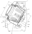
- FIG. 1 is a cross-sectional view of a drum-type washing machine according to an embodiment of the present invention.
- the rotary drum 31 has a bottomed cylindrical shape.
- a large number of water flow holes 32 are provided on the entire surface of the outer peripheral portion of the rotary drum 31.
- the water tank 33 rotatably includes the rotating drum 31.
- the rotation axis (rotation center axis) 34 passing through the rotation center of the rotation drum 31 is disposed so as to incline downward from the front side to the back side of the drum type washing machine.
- a belt 47 is connected to the rotation shaft 34, and a motor 35 located near the back side of the water tank 33 is connected to the belt 47. By driving the motor 35, the rotary drum 31 is rotationally driven in the normal direction and the reverse direction.
- the inclination angle of the rotary drum 31 and the rotation shaft 34 with respect to the horizontal direction is, for example, 10 degrees.
- the inner wall surface of the rotating drum 31 is provided with a plurality of wall surface baffles 36 which are projections for stirring the clothes.
- the inner bottom surface 40 of the rotary drum 31 is formed with a plurality of bottom surface baffles 46 that protrude higher toward the rotary shaft 34 (closer to the rotation center of the rotary drum 31).
- the rotation axis may be arranged horizontally.
- a ring-shaped protrusion 52 is formed on the outer peripheral side of the inner bottom surface of the water tank 33.
- the gap between the inner bottom surface of the water tank 33 and the outer bottom surface of the rotary drum 31 is reduced by the ring-shaped projection 52 to a size that is acceptable for manufacturing. Thereby, the flow velocity of the wind at the time of dehydration rotation is improved, and the pressure (sound pressure) is reduced. Therefore, wind noise is reduced.
- a drive shaft flange 51 for improving the strength of the rotary drum 31 is fixed to the outer bottom surface side of the rotary drum 31.
- a water tank unit 60 of a vibration system is configured by the rotary drum 31, the drive shaft flange 51, the water tank 33, the motor 35, and the like.
- An opening is provided on the upward inclined surface of the washing machine main body 39 located on the front opening side of the water tank 33, and the opening is covered with a lid 37 so as to be able to open and close.
- the lid 37 When the lid 37 is opened, the laundry can be taken in and out of the rotating drum 31 through the clothes inlet 38, which is an opening provided in the rotating drum 31.
- the vibration proofing member 41 is attached to the lower side, and the spring 48 is attached to the upper side.
- the water tank unit 60 is swingably supported by the anti-vibration member 41 and the spring 48 so as to be anti-vibration.
- One end of a drainage path 42 is connected to the lower portion of the water tank 33.
- the other end of the drainage path 42 is connected to the drainage valve 43.
- a feed valve 44 is provided above the inside of the washing machine body 39.
- a water supply path 45 is connected to the water supply valve 44.
- the water supply path 45 is in communication with the water tank 33 via the detergent case 53 (not shown in FIG. 1).
- the water supplied from the water supply path 45 enters the detergent case 53, dissolves the detergent in the detergent case 53, and enters the water tank 33 as washing water.
- the water supply valve 44 supplies the wash water into the water tank 33.
- control unit 56 is provided above the inside of the washing machine main body 39.
- the control unit 56 controls the operation of the motor 35 and the like, and controls each process such as washing, rinsing, and dewatering.
- the motor 35 configured by a DC brushless motor or the like is controlled to be variable in forward / reverse rotation and variable in rotational speed by the control unit 56, a drive circuit (not shown), or the like.
- an input setting unit 49 for the user to select a washing course and the like, and a display unit for notifying the user of the selection result, the progress of the process and operation error etc. And 50 are provided.
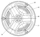
- FIG. 2 is a cross-sectional view of the bottom side of the rotary drum 31 of the drum-type washing machine according to the embodiment of the present invention.
- the inner wall surface of the rotary drum 31 is provided with a plurality of wall surface baffles 36 for agitating clothes
- the inner bottom surface of the rotary drum 31 is provided with a plurality of bottom surface baffles 46.
- the wall surface baffles 36 and the bottom surface baffles 46 are alternately arranged on the circumference centering on the rotating shaft 34 of the rotating drum 31.
- FIG. 2 shows the case where three wall surface baffles 36 and three bottom surface baffles 46 are provided, the number of each of the wall surface baffles 36 and the bottom surface baffles 46 is not limited to this, and can be set as appropriate.
- step S1 After the user opens the lid 37 and inserts the laundry into the rotary drum 31 and inserts a predetermined amount of detergent into the detergent case 53, the user operates the input setting unit 49 to operate the drum type washing machine. Start. When the operation is started, the washing step is first performed (step S1).
- the water supply valve 44 is actuated to supply the wash water.
- the supplied wash water passes through the water supply path 45 and the detergent case 53 and enters the water tank 33 together with the detergent.
- the motor 35 is controlled to increase the rotational speed of the rotary drum 31 to a predetermined rotational speed.
- the operation (washing operation) of repeating the cycle is performed for a predetermined time, with the forward rotation, the pause, the reverse, and the pause operation of the rotary drum 31 as one cycle.
- the drum-type washing machine rotates the laundry three-dimensionally in the rotating drum 31 without entangling the laundry, and performs the washing operation efficiently. Can be dispersed.
- the laundry is lifted so as to be held between the wall baffles 36 and the bottom baffles 46.
- the laundry is less likely to slip off the wall baffle 36 while being lifted by the wall baffle 36, and is pushed upward and then dropped. Therefore, the tap washing effect is obtained, and the washing performance is improved.
- a first drainage step (step S2) is performed.
- a rinsing step (step S3) is performed. Also in the rinsing step, the same washing operation as the washing step is performed. Thereafter, the drainage step (step S4) and the dewatering step (step S5) are performed.
- the plurality of wall surface baffles 36 provided on the inner wall surface of the rotating drum 31 and the plurality of bottom surface baffles 46 provided on the inner bottom surface of the rotating drum 31 are alternately arranged on the circumference centering on the rotation axis 34 of the rotation drum 31.
- the laundry is less likely to be entangled during the washing process or the rinsing process, and the laundry is three-dimensionally rotated in the rotating drum 31, and the stirring operation is performed efficiently. Therefore, the washing performance and the rinsing performance are improved, and the laundry is dispersed. Further, the dispersion of the laundry reduces vibration and noise at the time of dewatering.
- the washing machine according to the present invention can disperse the laundry without being entangled in the rotating drum and can efficiently perform the washing operation and the rinsing operation, it can be used for other uses such as other washing machines. Applicable
Landscapes
- Engineering & Computer Science (AREA)
- Textile Engineering (AREA)
- Main Body Construction Of Washing Machines And Laundry Dryers (AREA)
Priority Applications (3)
| Application Number | Priority Date | Filing Date | Title |
|---|---|---|---|
| US13/638,251 US20130025332A1 (en) | 2011-02-23 | 2012-02-22 | Drum-type washing machine |
| CN2012800009486A CN102812174A (zh) | 2011-02-23 | 2012-02-22 | 滚筒式洗衣机 |
| EP12749539.8A EP2562301B1 (en) | 2011-02-23 | 2012-02-22 | Drum-type washing machine |
Applications Claiming Priority (2)
| Application Number | Priority Date | Filing Date | Title |
|---|---|---|---|
| JP2011036735A JP2012170680A (ja) | 2011-02-23 | 2011-02-23 | ドラム式洗濯機 |
| JP2011-036735 | 2011-02-23 |
Publications (1)
| Publication Number | Publication Date |
|---|---|
| WO2012114741A1 true WO2012114741A1 (ja) | 2012-08-30 |
Family
ID=46720533
Family Applications (1)
| Application Number | Title | Priority Date | Filing Date |
|---|---|---|---|
| PCT/JP2012/001204 Ceased WO2012114741A1 (ja) | 2011-02-23 | 2012-02-22 | ドラム式洗濯機 |
Country Status (5)
| Country | Link |
|---|---|
| US (1) | US20130025332A1 (enExample) |
| EP (1) | EP2562301B1 (enExample) |
| JP (1) | JP2012170680A (enExample) |
| CN (1) | CN102812174A (enExample) |
| WO (1) | WO2012114741A1 (enExample) |
Cited By (1)
| Publication number | Priority date | Publication date | Assignee | Title |
|---|---|---|---|---|
| JP2014064727A (ja) * | 2012-09-26 | 2014-04-17 | Hitachi Appliances Inc | ドラム式洗濯機およびドラム式洗濯乾燥機 |
Families Citing this family (3)
| Publication number | Priority date | Publication date | Assignee | Title |
|---|---|---|---|---|
| JP6140022B2 (ja) * | 2013-07-26 | 2017-05-31 | シャープ株式会社 | 洗濯機 |
| WO2016144757A1 (en) * | 2015-03-06 | 2016-09-15 | Hg LAUNDRY SYSTEMS, LLC | Combination washer/dryer apparatus |
| CN107893261A (zh) * | 2017-12-21 | 2018-04-10 | 徐州腾宇羽绒制品设备有限公司 | 倾斜洗毛机 |
Citations (6)
| Publication number | Priority date | Publication date | Assignee | Title |
|---|---|---|---|---|
| JPH07116393A (ja) * | 1993-10-22 | 1995-05-09 | Matsushita Electric Ind Co Ltd | 衣類乾燥機 |
| JPH09215894A (ja) * | 1996-02-15 | 1997-08-19 | Matsushita Electric Ind Co Ltd | 洗濯機 |
| JP2002315985A (ja) * | 2001-04-20 | 2002-10-29 | Sanyo Electric Co Ltd | ドラム式洗濯機 |
| JP2006223452A (ja) * | 2005-02-16 | 2006-08-31 | Toshiba Corp | ドラム式洗濯機 |
| JP2009022688A (ja) | 2007-07-24 | 2009-02-05 | Panasonic Corp | ドラム式洗濯乾燥機 |
| JP2011036735A (ja) | 2009-08-06 | 2011-02-24 | Panasonic Electric Works Co Ltd | 静電霧化装置 |
Family Cites Families (8)
| Publication number | Priority date | Publication date | Assignee | Title |
|---|---|---|---|---|
| JPS47146Y1 (enExample) * | 1968-07-05 | 1972-01-06 | ||
| DE4021533A1 (de) * | 1990-07-06 | 1992-01-09 | Bauknecht Hausgeraete | Trockner oder waschtrockner mit einer waeschetrommel |
| KR101054408B1 (ko) * | 2004-04-19 | 2011-08-05 | 엘지전자 주식회사 | 세탁기 |
| KR101253566B1 (ko) * | 2005-07-07 | 2013-04-11 | 삼성전자주식회사 | 드럼세탁기 |
| JP4566112B2 (ja) * | 2005-10-27 | 2010-10-20 | 三洋電機株式会社 | 衣類乾燥機 |
| JP4275160B2 (ja) * | 2006-08-24 | 2009-06-10 | 三洋電機株式会社 | ドラム式洗濯機 |
| JP4893229B2 (ja) * | 2006-10-26 | 2012-03-07 | パナソニック株式会社 | ドラム式洗濯機 |
| JP4713620B2 (ja) * | 2008-09-05 | 2011-06-29 | 日立アプライアンス株式会社 | 洗濯乾燥機 |
-
2011
- 2011-02-23 JP JP2011036735A patent/JP2012170680A/ja active Pending
-
2012
- 2012-02-22 US US13/638,251 patent/US20130025332A1/en not_active Abandoned
- 2012-02-22 CN CN2012800009486A patent/CN102812174A/zh active Pending
- 2012-02-22 WO PCT/JP2012/001204 patent/WO2012114741A1/ja not_active Ceased
- 2012-02-22 EP EP12749539.8A patent/EP2562301B1/en not_active Not-in-force
Patent Citations (6)
| Publication number | Priority date | Publication date | Assignee | Title |
|---|---|---|---|---|
| JPH07116393A (ja) * | 1993-10-22 | 1995-05-09 | Matsushita Electric Ind Co Ltd | 衣類乾燥機 |
| JPH09215894A (ja) * | 1996-02-15 | 1997-08-19 | Matsushita Electric Ind Co Ltd | 洗濯機 |
| JP2002315985A (ja) * | 2001-04-20 | 2002-10-29 | Sanyo Electric Co Ltd | ドラム式洗濯機 |
| JP2006223452A (ja) * | 2005-02-16 | 2006-08-31 | Toshiba Corp | ドラム式洗濯機 |
| JP2009022688A (ja) | 2007-07-24 | 2009-02-05 | Panasonic Corp | ドラム式洗濯乾燥機 |
| JP2011036735A (ja) | 2009-08-06 | 2011-02-24 | Panasonic Electric Works Co Ltd | 静電霧化装置 |
Non-Patent Citations (1)
| Title |
|---|
| See also references of EP2562301A4 |
Cited By (1)
| Publication number | Priority date | Publication date | Assignee | Title |
|---|---|---|---|---|
| JP2014064727A (ja) * | 2012-09-26 | 2014-04-17 | Hitachi Appliances Inc | ドラム式洗濯機およびドラム式洗濯乾燥機 |
Also Published As
| Publication number | Publication date |
|---|---|
| CN102812174A (zh) | 2012-12-05 |
| JP2012170680A (ja) | 2012-09-10 |
| EP2562301A4 (en) | 2013-09-25 |
| EP2562301B1 (en) | 2014-12-31 |
| EP2562301A1 (en) | 2013-02-27 |
| US20130025332A1 (en) | 2013-01-31 |
Similar Documents
| Publication | Publication Date | Title |
|---|---|---|
| KR101555899B1 (ko) | 세탁기용 펄세이터유닛 및 이를 갖는 세탁기 | |
| CN101994230B (zh) | 洗衣机、洗衣机的内桶和平衡器的连接及其装配方法 | |
| JP6379436B2 (ja) | 洗濯機 | |
| WO2012114741A1 (ja) | ドラム式洗濯機 | |
| JP7222607B2 (ja) | 洗濯機 | |
| CN112424413B (zh) | 滚筒式洗衣机 | |
| JP5784532B2 (ja) | 洗濯機 | |
| JP2015223318A (ja) | 洗濯機 | |
| KR102861424B1 (ko) | 의류처리장치 및 그 제어방법 | |
| JP7344633B2 (ja) | 洗濯機 | |
| KR20180016863A (ko) | 의류처리장치 및 의류처리장치의 제어방법 | |
| JP6235200B2 (ja) | 洗濯機 | |
| JP7556816B2 (ja) | 洗濯機 | |
| US20030115913A1 (en) | Washing machine with an improved water tub | |
| JP2013013603A (ja) | 洗濯機 | |
| KR20130037411A (ko) | 임펠러를 구비하는 세탁기 | |
| KR20220026862A (ko) | 의류처리장치 | |
| JP6553448B2 (ja) | ドラム式洗濯機 | |
| JP6060369B2 (ja) | 洗濯機 | |
| JP7292640B2 (ja) | 縦型洗濯機 | |
| JP2020065623A (ja) | ドラム式洗濯機 | |
| JP2023035691A (ja) | 洗濯機 | |
| JP2006223452A (ja) | ドラム式洗濯機 | |
| JP2023140899A (ja) | ドラム式洗濯機 | |
| JP2023035692A (ja) | 洗濯機 |
Legal Events
| Date | Code | Title | Description |
|---|---|---|---|
| WWE | Wipo information: entry into national phase |
Ref document number: 201280000948.6 Country of ref document: CN |
|
| WWE | Wipo information: entry into national phase |
Ref document number: 2012749539 Country of ref document: EP |
|
| WWE | Wipo information: entry into national phase |
Ref document number: 13638251 Country of ref document: US |
|
| 121 | Ep: the epo has been informed by wipo that ep was designated in this application |
Ref document number: 12749539 Country of ref document: EP Kind code of ref document: A1 |
|
| NENP | Non-entry into the national phase |
Ref country code: DE |