WO2012114741A1 - Drum-type washing machine - Google Patents
Drum-type washing machine Download PDFInfo
- Publication number
- WO2012114741A1 WO2012114741A1 PCT/JP2012/001204 JP2012001204W WO2012114741A1 WO 2012114741 A1 WO2012114741 A1 WO 2012114741A1 JP 2012001204 W JP2012001204 W JP 2012001204W WO 2012114741 A1 WO2012114741 A1 WO 2012114741A1
- Authority
- WO
- WIPO (PCT)
- Prior art keywords
- drum
- baffles
- washing machine
- rotating drum
- type washing
- Prior art date
Links
Images

Classifications
-
- D—TEXTILES; PAPER
- D06—TREATMENT OF TEXTILES OR THE LIKE; LAUNDERING; FLEXIBLE MATERIALS NOT OTHERWISE PROVIDED FOR
- D06F—LAUNDERING, DRYING, IRONING, PRESSING OR FOLDING TEXTILE ARTICLES
- D06F23/00—Washing machines with receptacles, e.g. perforated, having a rotary movement, e.g. oscillatory movement, the receptacle serving both for washing and for centrifugally separating water from the laundry
- D06F23/02—Washing machines with receptacles, e.g. perforated, having a rotary movement, e.g. oscillatory movement, the receptacle serving both for washing and for centrifugally separating water from the laundry and rotating or oscillating about a horizontal axis
-
- D—TEXTILES; PAPER
- D06—TREATMENT OF TEXTILES OR THE LIKE; LAUNDERING; FLEXIBLE MATERIALS NOT OTHERWISE PROVIDED FOR
- D06F—LAUNDERING, DRYING, IRONING, PRESSING OR FOLDING TEXTILE ARTICLES
- D06F23/00—Washing machines with receptacles, e.g. perforated, having a rotary movement, e.g. oscillatory movement, the receptacle serving both for washing and for centrifugally separating water from the laundry
- D06F23/06—Washing machines with receptacles, e.g. perforated, having a rotary movement, e.g. oscillatory movement, the receptacle serving both for washing and for centrifugally separating water from the laundry and rotating or oscillating about an inclined axis
-
- D—TEXTILES; PAPER
- D06—TREATMENT OF TEXTILES OR THE LIKE; LAUNDERING; FLEXIBLE MATERIALS NOT OTHERWISE PROVIDED FOR
- D06F—LAUNDERING, DRYING, IRONING, PRESSING OR FOLDING TEXTILE ARTICLES
- D06F37/00—Details specific to washing machines covered by groups D06F21/00 - D06F25/00
- D06F37/02—Rotary receptacles, e.g. drums
- D06F37/04—Rotary receptacles, e.g. drums adapted for rotation or oscillation about a horizontal or inclined axis
- D06F37/06—Ribs, lifters, or rubbing means forming part of the receptacle
Definitions
- the present invention relates to a drum-type washing machine for washing laundry in a rotating drum.
- FIG. 3 shows a cross-sectional view of a conventional drum-type washing machine described in Patent Document 1. As shown in FIG.
- a water tank 2 supported by a plurality of suspensions (not shown) is disposed in a housing 1.
- the water tank 2 has a substantially cylindrical shape that is axially symmetrical around the rotation axis.
- the rotation axis of the water tank 2 is inclined forward with respect to the horizontal direction so that the bottom 4a side of the water tank 2 is lower than the opening 2a on the front side of the water tank 2.
- the drum 4 which has many holes 3 in the surrounding wall is arrange
- the drum 4 is rotationally driven by a drive device 5 such as a motor provided on the bottom of the water tank 2.
- the drum 4 rotates in both forward and reverse directions (forward and reverse rotation).
- the clothes A in the drum 4 are lifted by the baffles 6 provided on the peripheral wall in the drum 4 and fall. Thereby, the clothes A are agitated.
- the baffle 6 extends from the bottom portion 4 a in the drum 4 toward the opening 2 a and protrudes inward in the rotational axis direction of the drum 4.
- the size of the baffle 6 is larger on the bottom surface 4 a side than on the opening 2 a side.
- the drum 4 has a tapered structure in which the diameter of the front surface portion is larger than the diameter of the bottom surface portion (i.e., the tapered structure with the larger diameter on the front surface side).
- An auxiliary baffle 21 is provided on the bottom 4 a of the drum 4.
- the auxiliary baffle 21 is connected to both side surfaces 6 a of the baffle 6 to form an inclined surface 21 a that expands toward the bottom surface 4 a of the drum 4.
- the auxiliary baffle 21 enables the laundry to be moved to the front side of the drum 4.
- the drum 4 has a tapered structure with a large diameter on the front side, so when the drum 4 rotates, the laundry tends to move to the front side of the drum 4.
- the peripheral speed of the drum is fast, so the laundry is easily entangled (it is easy to be solidified). That is, since the laundry tangled in the bottom surface portion 4 a of the drum 4 moves to the front side of the drum 4, the laundry can not be efficiently performed.
- the inside of the drum 4 becomes unbalanced (unstable state), and vibration is increased at the time of dewatering.
- the present invention is to solve the above-mentioned conventional problems, and it is an object of the present invention to provide a drum type washing machine capable of reducing vibration at the time of dewatering by dispersing the laundry by efficiently performing stirring operation. Do.
- the drum-type washing machine has a rotating drum arranged horizontally or a rotating drum arranged such that the rotating shaft is inclined downward from the front side to the back side
- a water tank rotatably containing the rotary drum, and a motor rotatably driving the rotary drum, wherein the rotary drum has a plurality of wall surface baffles on an inner wall surface, and a plurality of bottom surface baffles on an inner bottom surface
- the wall surface baffles and the bottom surface baffles are alternately arranged on a circumference centered on the rotation axis.
- the agitation operation is performed efficiently to disperse the laundry, whereby the vibration at the time of dewatering is reduced.
- the drum type washing machine of the present invention can reduce vibrations at the time of dewatering by dispersing the laundry by efficiently performing the stirring operation.
- a rotating drum having a rotating shaft disposed horizontally or having a rotating shaft inclined downward from a front side toward a back side, and a water tank rotatably containing the rotating drum. And a motor for rotationally driving the rotating drum, the rotating drum having a plurality of wall baffles on an inner wall surface, and further having a plurality of bottom baffles on an inner bottom surface, the wall baffle and the bottom baffle It is a drum type washing machine alternately arranged on the circumference centering on the above-mentioned axis of rotation. With such a configuration, the vibration at the time of dehydration can be reduced by efficiently performing the stirring operation to disperse the laundry.
- the bottom baffle protrudes higher toward the rotation axis of the rotating drum. According to such a configuration, the laundry is pushed out and dispersed to the opening side of the rotary drum.
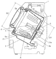
- FIG. 1 is a cross-sectional view of a drum-type washing machine according to an embodiment of the present invention.
- the rotary drum 31 has a bottomed cylindrical shape.
- a large number of water flow holes 32 are provided on the entire surface of the outer peripheral portion of the rotary drum 31.
- the water tank 33 rotatably includes the rotating drum 31.
- the rotation axis (rotation center axis) 34 passing through the rotation center of the rotation drum 31 is disposed so as to incline downward from the front side to the back side of the drum type washing machine.
- a belt 47 is connected to the rotation shaft 34, and a motor 35 located near the back side of the water tank 33 is connected to the belt 47. By driving the motor 35, the rotary drum 31 is rotationally driven in the normal direction and the reverse direction.
- the inclination angle of the rotary drum 31 and the rotation shaft 34 with respect to the horizontal direction is, for example, 10 degrees.
- the inner wall surface of the rotating drum 31 is provided with a plurality of wall surface baffles 36 which are projections for stirring the clothes.
- the inner bottom surface 40 of the rotary drum 31 is formed with a plurality of bottom surface baffles 46 that protrude higher toward the rotary shaft 34 (closer to the rotation center of the rotary drum 31).
- the rotation axis may be arranged horizontally.
- a ring-shaped protrusion 52 is formed on the outer peripheral side of the inner bottom surface of the water tank 33.
- the gap between the inner bottom surface of the water tank 33 and the outer bottom surface of the rotary drum 31 is reduced by the ring-shaped projection 52 to a size that is acceptable for manufacturing. Thereby, the flow velocity of the wind at the time of dehydration rotation is improved, and the pressure (sound pressure) is reduced. Therefore, wind noise is reduced.
- a drive shaft flange 51 for improving the strength of the rotary drum 31 is fixed to the outer bottom surface side of the rotary drum 31.
- a water tank unit 60 of a vibration system is configured by the rotary drum 31, the drive shaft flange 51, the water tank 33, the motor 35, and the like.
- An opening is provided on the upward inclined surface of the washing machine main body 39 located on the front opening side of the water tank 33, and the opening is covered with a lid 37 so as to be able to open and close.
- the lid 37 When the lid 37 is opened, the laundry can be taken in and out of the rotating drum 31 through the clothes inlet 38, which is an opening provided in the rotating drum 31.
- the vibration proofing member 41 is attached to the lower side, and the spring 48 is attached to the upper side.
- the water tank unit 60 is swingably supported by the anti-vibration member 41 and the spring 48 so as to be anti-vibration.
- One end of a drainage path 42 is connected to the lower portion of the water tank 33.
- the other end of the drainage path 42 is connected to the drainage valve 43.
- a feed valve 44 is provided above the inside of the washing machine body 39.
- a water supply path 45 is connected to the water supply valve 44.
- the water supply path 45 is in communication with the water tank 33 via the detergent case 53 (not shown in FIG. 1).
- the water supplied from the water supply path 45 enters the detergent case 53, dissolves the detergent in the detergent case 53, and enters the water tank 33 as washing water.
- the water supply valve 44 supplies the wash water into the water tank 33.
- control unit 56 is provided above the inside of the washing machine main body 39.
- the control unit 56 controls the operation of the motor 35 and the like, and controls each process such as washing, rinsing, and dewatering.
- the motor 35 configured by a DC brushless motor or the like is controlled to be variable in forward / reverse rotation and variable in rotational speed by the control unit 56, a drive circuit (not shown), or the like.
- an input setting unit 49 for the user to select a washing course and the like, and a display unit for notifying the user of the selection result, the progress of the process and operation error etc. And 50 are provided.
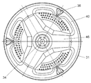
- FIG. 2 is a cross-sectional view of the bottom side of the rotary drum 31 of the drum-type washing machine according to the embodiment of the present invention.
- the inner wall surface of the rotary drum 31 is provided with a plurality of wall surface baffles 36 for agitating clothes
- the inner bottom surface of the rotary drum 31 is provided with a plurality of bottom surface baffles 46.
- the wall surface baffles 36 and the bottom surface baffles 46 are alternately arranged on the circumference centering on the rotating shaft 34 of the rotating drum 31.
- FIG. 2 shows the case where three wall surface baffles 36 and three bottom surface baffles 46 are provided, the number of each of the wall surface baffles 36 and the bottom surface baffles 46 is not limited to this, and can be set as appropriate.
- step S1 After the user opens the lid 37 and inserts the laundry into the rotary drum 31 and inserts a predetermined amount of detergent into the detergent case 53, the user operates the input setting unit 49 to operate the drum type washing machine. Start. When the operation is started, the washing step is first performed (step S1).
- the water supply valve 44 is actuated to supply the wash water.
- the supplied wash water passes through the water supply path 45 and the detergent case 53 and enters the water tank 33 together with the detergent.
- the motor 35 is controlled to increase the rotational speed of the rotary drum 31 to a predetermined rotational speed.
- the operation (washing operation) of repeating the cycle is performed for a predetermined time, with the forward rotation, the pause, the reverse, and the pause operation of the rotary drum 31 as one cycle.
- the drum-type washing machine rotates the laundry three-dimensionally in the rotating drum 31 without entangling the laundry, and performs the washing operation efficiently. Can be dispersed.
- the laundry is lifted so as to be held between the wall baffles 36 and the bottom baffles 46.
- the laundry is less likely to slip off the wall baffle 36 while being lifted by the wall baffle 36, and is pushed upward and then dropped. Therefore, the tap washing effect is obtained, and the washing performance is improved.
- a first drainage step (step S2) is performed.
- a rinsing step (step S3) is performed. Also in the rinsing step, the same washing operation as the washing step is performed. Thereafter, the drainage step (step S4) and the dewatering step (step S5) are performed.
- the plurality of wall surface baffles 36 provided on the inner wall surface of the rotating drum 31 and the plurality of bottom surface baffles 46 provided on the inner bottom surface of the rotating drum 31 are alternately arranged on the circumference centering on the rotation axis 34 of the rotation drum 31.
- the laundry is less likely to be entangled during the washing process or the rinsing process, and the laundry is three-dimensionally rotated in the rotating drum 31, and the stirring operation is performed efficiently. Therefore, the washing performance and the rinsing performance are improved, and the laundry is dispersed. Further, the dispersion of the laundry reduces vibration and noise at the time of dewatering.
- the washing machine according to the present invention can disperse the laundry without being entangled in the rotating drum and can efficiently perform the washing operation and the rinsing operation, it can be used for other uses such as other washing machines. Applicable
Abstract
This drum-type washing machine is provided with: a rotating drum (31), the axis of rotation (34) of which is horizontal or slanted downwards from the front to the back; a water tank that rotatably encloses said rotating drum (31); and a motor that rotationally drives the rotating drum (31). The rotating drum (31) has a plurality of wall baffles (36) on the interior wall thereof and a plurality of bottom baffles (46) on the inside bottom surface (40). Said wall baffles (36) and bottom baffles (46) are arranged in alternation on a circle centered on the axis of rotation (34), thereby dispersing garments throughout the drum and improving washing performance.
Description
本発明は、回転ドラム内の洗濯物を洗濯するドラム式洗濯機に関する。
The present invention relates to a drum-type washing machine for washing laundry in a rotating drum.
従来、この種の洗濯機において、洗濯物を分散させるために、回転ドラム内にバッフルが設けられた構成や、バッフルの形状や回転ドラムの形状に工夫が加えられた構成が提案されてきた(例えば、特許文献1参照)。
Heretofore, in this type of washing machine, in order to disperse the laundry, there has been proposed a configuration in which a baffle is provided in the rotating drum, and a configuration in which the shape of the baffle and the shape of the rotating drum are devised For example, refer to Patent Document 1).
図3は、特許文献1に記載された従来のドラム式洗濯機の断面図を示す。
FIG. 3 shows a cross-sectional view of a conventional drum-type washing machine described in Patent Document 1. As shown in FIG.
図3に示されるように、筺体1内に、複数のサスペンション(図示せず)で支持された水槽2が配設されている。水槽2は、回転軸周りに軸対称な略筒形状を有する。水槽2の前面側の開口部2aよりも水槽2の底面部4a側が下側となるように、水槽2の回転軸は、水平方向に対して前上がりに傾斜している。水槽2の内部には、周壁に多数の孔3を有したドラム4が配置されている。ドラム4は、水槽2の底面部に設けられたモータ等の駆動装置5によって、回転駆動される。ドラム4は、正方向および逆方向の両方向に回転する(正逆回転)。
As shown in FIG. 3, a water tank 2 supported by a plurality of suspensions (not shown) is disposed in a housing 1. The water tank 2 has a substantially cylindrical shape that is axially symmetrical around the rotation axis. The rotation axis of the water tank 2 is inclined forward with respect to the horizontal direction so that the bottom 4a side of the water tank 2 is lower than the opening 2a on the front side of the water tank 2. Inside the water tank 2, the drum 4 which has many holes 3 in the surrounding wall is arrange | positioned. The drum 4 is rotationally driven by a drive device 5 such as a motor provided on the bottom of the water tank 2. The drum 4 rotates in both forward and reverse directions (forward and reverse rotation).
正逆回転時において、ドラム4内の衣類Aは、ドラム4内の周壁に複数設けられたバッフル6によって持ち上げられて、落下する。これにより、衣類Aは撹拌される。バッフル6は、ドラム4内の底面部4aから開口部2aに向かって延びるとともに、ドラム4の回転軸心方向へ内方に突出する。バッフル6の大きさは、開口部2a側よりも底面部4a側の方が大きくなっている。
At the time of forward and reverse rotation, the clothes A in the drum 4 are lifted by the baffles 6 provided on the peripheral wall in the drum 4 and fall. Thereby, the clothes A are agitated. The baffle 6 extends from the bottom portion 4 a in the drum 4 toward the opening 2 a and protrudes inward in the rotational axis direction of the drum 4. The size of the baffle 6 is larger on the bottom surface 4 a side than on the opening 2 a side.
ドラム4の底面部4aの内径がD1、ドラム4の前面部の内径がD2とすると、D1<D2となる。すなわち、ドラム4は、前面部の径が底面部の径よりも大きいテーパー構造(すなわち、前面側が径大のテーパー構造)を有する。
Assuming that the inner diameter of the bottom surface portion 4a of the drum 4 is D1 and the inner diameter of the front surface portion of the drum 4 is D2, D1 <D2. That is, the drum 4 has a tapered structure in which the diameter of the front surface portion is larger than the diameter of the bottom surface portion (i.e., the tapered structure with the larger diameter on the front surface side).
ドラム4の底面部4aには、補助バッフル21が設けられる。補助バッフル21は、バッフル6の両側面6aに連接され、ドラム4の底面部4aに向かって拡がる傾斜面21aを形成する。ドラム4の正逆回転のいずれの場合でも、補助バッフル21によって、洗濯物をドラム4の前面部側へ移動させることが可能となる。
An auxiliary baffle 21 is provided on the bottom 4 a of the drum 4. The auxiliary baffle 21 is connected to both side surfaces 6 a of the baffle 6 to form an inclined surface 21 a that expands toward the bottom surface 4 a of the drum 4. In any of the forward and reverse rotation of the drum 4, the auxiliary baffle 21 enables the laundry to be moved to the front side of the drum 4.
しかしながら、前記従来の構成では、ドラム4は前面側が径大のテーパー構造を有するため、ドラム4が回転すると、洗濯物はドラム4の前面側へ移動しやすい。一方で、ドラム4の底面部4a側では、ドラムの周速度が速いため、洗濯物が絡みやすい(固まりやすい)。つまり、ドラム4の底面部4aで絡んだ洗濯物がドラム4の前面側へ移動するため、洗濯が効率よく行なわれない。また、洗濯物が片寄ることにより、ドラム4内部がアンバランス状態(不安定な状態)となり、脱水時に振動が大きくなってしまう。
However, in the conventional configuration, the drum 4 has a tapered structure with a large diameter on the front side, so when the drum 4 rotates, the laundry tends to move to the front side of the drum 4. On the other hand, on the side of the bottom portion 4 a of the drum 4, the peripheral speed of the drum is fast, so the laundry is easily entangled (it is easy to be solidified). That is, since the laundry tangled in the bottom surface portion 4 a of the drum 4 moves to the front side of the drum 4, the laundry can not be efficiently performed. In addition, when the laundry is offset, the inside of the drum 4 becomes unbalanced (unstable state), and vibration is increased at the time of dewatering.
本発明は、前記従来の課題を解決するもので、効率よく撹拌動作を行なって洗濯物を分散させることにより、脱水時における振動を低減することができるドラム式洗濯機を提供することを目的とする。
The present invention is to solve the above-mentioned conventional problems, and it is an object of the present invention to provide a drum type washing machine capable of reducing vibration at the time of dewatering by dispersing the laundry by efficiently performing stirring operation. Do.
前記従来の課題を解決するために、本発明のドラム式洗濯機は、回転軸が水平に配置され、または回転軸が正面側から背面側に向かって下向きに傾斜して配置された回転ドラムと、前記回転ドラムを回転自在に内包する水槽と、前記回転ドラムを回転駆動するモータとを備え、前記回転ドラムは、内壁面に複数の壁面バッフルを有し、さらに内底面に複数の底面バッフルを有し、前記壁面バッフルと前記底面バッフルとは、前記回転軸を中心とする円周上で交互に配置されたものである。
In order to solve the above-mentioned conventional problems, the drum-type washing machine according to the present invention has a rotating drum arranged horizontally or a rotating drum arranged such that the rotating shaft is inclined downward from the front side to the back side A water tank rotatably containing the rotary drum, and a motor rotatably driving the rotary drum, wherein the rotary drum has a plurality of wall surface baffles on an inner wall surface, and a plurality of bottom surface baffles on an inner bottom surface The wall surface baffles and the bottom surface baffles are alternately arranged on a circumference centered on the rotation axis.
これによって、効率よく撹拌動作が行なわれて洗濯物が分散されることにより、脱水時における振動が低減される。
As a result, the agitation operation is performed efficiently to disperse the laundry, whereby the vibration at the time of dewatering is reduced.
本発明のドラム式洗濯機は、効率よく撹拌動作を行なって洗濯物を分散させることにより、脱水時における振動を低減することができる。
The drum type washing machine of the present invention can reduce vibrations at the time of dewatering by dispersing the laundry by efficiently performing the stirring operation.
本発明のこれらの態様と特徴は、添付された図面についての好ましい実施の形態に関連した次の記述から明らかになる。
本発明の実施の形態におけるドラム式洗濯機の断面図
同ドラム式洗濯機の回転ドラムの底面部を示す断面図
従来のドラム式洗濯機の断面図
These aspects and features of the present invention will become apparent from the following description in connection with the preferred embodiments of the attached drawings.
Cross-sectional view of a drum-type washing machine according to an embodiment of the present invention Sectional drawing which shows the bottom part of the rotating drum of the drum type washing machine. Cross section of a conventional drum-type washing machine
第1の発明は、回転軸が水平に配置され、または回転軸が正面側から背面側に向かって下向きに傾斜して配置された回転ドラムと、前記回転ドラムを回転自在に内包する水槽と、前記回転ドラムを回転駆動するモータとを備え、前記回転ドラムは、内壁面に複数の壁面バッフルを有し、さらに内底面に複数の底面バッフルを有し、前記壁面バッフルと前記底面バッフルとは、前記回転軸を中心とする円周上で交互に配置されたドラム式洗濯機である。このような構成により、効率よく撹拌動作を行なって洗濯物を分散させることにより、脱水時における振動を低減することができる。
According to a first aspect of the present invention, there is provided a rotating drum having a rotating shaft disposed horizontally or having a rotating shaft inclined downward from a front side toward a back side, and a water tank rotatably containing the rotating drum. And a motor for rotationally driving the rotating drum, the rotating drum having a plurality of wall baffles on an inner wall surface, and further having a plurality of bottom baffles on an inner bottom surface, the wall baffle and the bottom baffle It is a drum type washing machine alternately arranged on the circumference centering on the above-mentioned axis of rotation. With such a configuration, the vibration at the time of dehydration can be reduced by efficiently performing the stirring operation to disperse the laundry.
第2の発明は、第1の発明のドラム式洗濯機において、前記底面バッフルは、前記回転ドラムの回転軸に向かうほど高く突出した。このような構成により、回転ドラムの開口部側へ洗濯物が押し出されて分散される。
According to a second invention, in the drum-type washing machine of the first invention, the bottom baffle protrudes higher toward the rotation axis of the rotating drum. According to such a configuration, the laundry is pushed out and dispersed to the opening side of the rotary drum.
本発明の記述を続ける前に、添付図面において同じ部品については、同じ参照符号が付されている。以下、本発明の実施の形態が、図面を参照しながら説明される。なお、この実施の形態によって本発明は限定されない。
Before continuing with the description of the present invention, the same parts are given the same reference numerals in the attached drawings. Hereinafter, embodiments of the present invention will be described with reference to the drawings. The present invention is not limited by this embodiment.
(実施の形態)
図1は、本発明の実施の形態におけるドラム式洗濯機の断面図を示すものである。 Embodiment
FIG. 1 is a cross-sectional view of a drum-type washing machine according to an embodiment of the present invention.
図1は、本発明の実施の形態におけるドラム式洗濯機の断面図を示すものである。 Embodiment
FIG. 1 is a cross-sectional view of a drum-type washing machine according to an embodiment of the present invention.
図1に示されるように、回転ドラム31は、有底円筒形状を有する。回転ドラム31の外周部の全面には、多数の通水孔32が設けられている。水槽33は、回転ドラム31を回転自在に内包する。回転ドラム31の回転中心を通る回転軸(回転中心軸)34は、ドラム式洗濯機の正面側から背面側に向かって下向きに傾斜して配置されている。回転軸34にベルト47が連結され、ベルト47に、水槽33の背面側近傍に位置するモータ35が連結される。モータ35が駆動されることにより、回転ドラム31が正転方向および逆転方向に回転駆動される。水平方向に対する回転ドラム31および回転軸34の傾斜角度は例えば10度とする。回転ドラム31の内壁面には、衣類を撹拌するための突出部である複数の壁面バッフル36が設けられている。回転ドラム31の内底面40には、回転軸34に向かうほど(回転ドラム31の回転中心に近いほど)高く突出した複数の底面バッフル46が形成されている。なお、本実施の形態では、回転軸が正面側から背面側に向かって下向きに傾斜して配置された場合について説明したが、回転軸は水平に配置されても良い。
As shown in FIG. 1, the rotary drum 31 has a bottomed cylindrical shape. A large number of water flow holes 32 are provided on the entire surface of the outer peripheral portion of the rotary drum 31. The water tank 33 rotatably includes the rotating drum 31. The rotation axis (rotation center axis) 34 passing through the rotation center of the rotation drum 31 is disposed so as to incline downward from the front side to the back side of the drum type washing machine. A belt 47 is connected to the rotation shaft 34, and a motor 35 located near the back side of the water tank 33 is connected to the belt 47. By driving the motor 35, the rotary drum 31 is rotationally driven in the normal direction and the reverse direction. The inclination angle of the rotary drum 31 and the rotation shaft 34 with respect to the horizontal direction is, for example, 10 degrees. The inner wall surface of the rotating drum 31 is provided with a plurality of wall surface baffles 36 which are projections for stirring the clothes. The inner bottom surface 40 of the rotary drum 31 is formed with a plurality of bottom surface baffles 46 that protrude higher toward the rotary shaft 34 (closer to the rotation center of the rotary drum 31). In the present embodiment, although the case where the rotation axis is arranged to be inclined downward from the front side to the back side has been described, the rotation axis may be arranged horizontally.
水槽33の内底面の外周側には、リング状突起52が形成される。水槽33の内底面と回転ドラム31の外底面との隙間は、リング状突起52によって、製造上許容できる寸法まで小さくされる。これにより、脱水回転時の風の流速が向上し、圧力(音圧)が下がる。したがって、風切り音が低減される。
A ring-shaped protrusion 52 is formed on the outer peripheral side of the inner bottom surface of the water tank 33. The gap between the inner bottom surface of the water tank 33 and the outer bottom surface of the rotary drum 31 is reduced by the ring-shaped projection 52 to a size that is acceptable for manufacturing. Thereby, the flow velocity of the wind at the time of dehydration rotation is improved, and the pressure (sound pressure) is reduced. Therefore, wind noise is reduced.
また、回転ドラム31の外底面側には、回転ドラム31の強度を向上させるためのドライブシャフトフランジ51が固着されている。
Further, a drive shaft flange 51 for improving the strength of the rotary drum 31 is fixed to the outer bottom surface side of the rotary drum 31.
回転ドラム31、ドライブシャフトフランジ51、水槽33およびモータ35等により、振動系の水槽ユニット60が構成されている。
A water tank unit 60 of a vibration system is configured by the rotary drum 31, the drive shaft flange 51, the water tank 33, the motor 35, and the like.
水槽33の正面開口部側に位置する洗濯機本体39の上向き傾斜面には、開口部が設けられており、開口部は、蓋体37により開閉自在に覆われる。蓋体37が開かれることにより、回転ドラム31に設けられた開口部である衣類出入口38を通じて、回転ドラム31内への洗濯物の出し入れが可能となる。
An opening is provided on the upward inclined surface of the washing machine main body 39 located on the front opening side of the water tank 33, and the opening is covered with a lid 37 so as to be able to open and close. When the lid 37 is opened, the laundry can be taken in and out of the rotating drum 31 through the clothes inlet 38, which is an opening provided in the rotating drum 31.
洗濯機本体39の内部において、下方には防振部材41が取り付けられ、上方にはばね体48が取り付けられる。水槽ユニット60は、防振部材41およびばね体48によって揺動自在に防振支持される。
In the inside of the washing machine main body 39, the vibration proofing member 41 is attached to the lower side, and the spring 48 is attached to the upper side. The water tank unit 60 is swingably supported by the anti-vibration member 41 and the spring 48 so as to be anti-vibration.
水槽33の下部には、排水経路42の一端が接続される。排水経路42の他端は排水弁43に接続される。このように排水経路42が接続されることにより、水槽33内の洗濯水は、ドラム式洗濯機の外部に排水される。
One end of a drainage path 42 is connected to the lower portion of the water tank 33. The other end of the drainage path 42 is connected to the drainage valve 43. By connecting the drainage path 42 in this manner, the washing water in the water tank 33 is drained to the outside of the drum-type washing machine.
洗濯機本体39内部の上方には、給水弁44が設けられている。給水弁44には、給水経路45が接続されている。給水経路45は、洗剤ケース53を介して水槽33に連通している(図1では図示せず)。給水経路45から給水された水は、洗剤ケース53に入り、洗剤ケース53内の洗剤を溶解し、洗濯水として水槽33に入る。このようにして、給水弁44は、水槽33内に洗濯水を給水する。
A feed valve 44 is provided above the inside of the washing machine body 39. A water supply path 45 is connected to the water supply valve 44. The water supply path 45 is in communication with the water tank 33 via the detergent case 53 (not shown in FIG. 1). The water supplied from the water supply path 45 enters the detergent case 53, dissolves the detergent in the detergent case 53, and enters the water tank 33 as washing water. Thus, the water supply valve 44 supplies the wash water into the water tank 33.
また、洗濯機本体39内部の上方には、制御部56が設けられている。制御部56は、モータ35等の動作を制御するとともに、洗い、すすぎ、および脱水等の各工程を制御する。
Further, a control unit 56 is provided above the inside of the washing machine main body 39. The control unit 56 controls the operation of the motor 35 and the like, and controls each process such as washing, rinsing, and dewatering.
直流ブラシレスモータ等で構成されるモータ35は、制御部56および駆動回路(図示せず)等によって、正逆回転可変および回転数可変に制御される。
The motor 35 configured by a DC brushless motor or the like is controlled to be variable in forward / reverse rotation and variable in rotational speed by the control unit 56, a drive circuit (not shown), or the like.
また、洗濯機本体39の前面上部には、使用者が洗濯コース等を選択するための入力設定部49と、選択結果、工程の進行度合いおよび動作エラー等を表示して使用者に知らせる表示部50とが設けられている。
In the upper front of the washing machine main body 39, an input setting unit 49 for the user to select a washing course and the like, and a display unit for notifying the user of the selection result, the progress of the process and operation error etc. And 50 are provided.
図2は、本発明の実施の形態におけるドラム式洗濯機の回転ドラム31の底面側を見た断面図である。
FIG. 2 is a cross-sectional view of the bottom side of the rotary drum 31 of the drum-type washing machine according to the embodiment of the present invention.
図2において、前述したように、回転ドラム31の内壁面には、衣類撹拌用の複数の壁面バッフル36が設けられており、回転ドラム31の内底面には、複数の底面バッフル46が設けられている。壁面バッフル36と底面バッフル46は、回転ドラム31の回転軸34を中心とする円周上において交互に配置されている。図2は、壁面バッフル36と底面バッフル46がそれぞれ3つずつ設けられた場合について示しているが、壁面バッフル36と底面バッフル46の各個数は、これに限らず、適宜設定可能である。
In FIG. 2, as described above, the inner wall surface of the rotary drum 31 is provided with a plurality of wall surface baffles 36 for agitating clothes, and the inner bottom surface of the rotary drum 31 is provided with a plurality of bottom surface baffles 46. ing. The wall surface baffles 36 and the bottom surface baffles 46 are alternately arranged on the circumference centering on the rotating shaft 34 of the rotating drum 31. Although FIG. 2 shows the case where three wall surface baffles 36 and three bottom surface baffles 46 are provided, the number of each of the wall surface baffles 36 and the bottom surface baffles 46 is not limited to this, and can be set as appropriate.
以上のように構成されたドラム式洗濯機の動作および作用が、以下で説明される。
The operation and action of the drum-type washing machine configured as described above will be described below.
使用者が、蓋体37を開いて回転ドラム31内に洗濯物を投入し、洗剤ケース53内に所定量の洗剤を投入した後、入力設定部49を操作してドラム式洗濯機の運転を開始する。運転が開始されると、まず、洗い工程が実行される(ステップS1)。
After the user opens the lid 37 and inserts the laundry into the rotary drum 31 and inserts a predetermined amount of detergent into the detergent case 53, the user operates the input setting unit 49 to operate the drum type washing machine. Start. When the operation is started, the washing step is first performed (step S1).
洗い工程において、給水弁44が作動することにより、洗濯水が給水される。給水された洗濯水は、給水経路45および洗剤ケース53を通り、洗剤とともに水槽33内に入る。所定の水位まで洗濯水が給水された後、モータ35が制御されて、回転ドラム31の回転速度が所定の回転速度まで上昇される。その後、回転ドラム31の正転、休止、反転、休止の動作を1サイクルとして、そのサイクルを繰り返す動作(洗い動作)が所定時間実行される。
In the washing step, the water supply valve 44 is actuated to supply the wash water. The supplied wash water passes through the water supply path 45 and the detergent case 53 and enters the water tank 33 together with the detergent. After the washing water is supplied to a predetermined water level, the motor 35 is controlled to increase the rotational speed of the rotary drum 31 to a predetermined rotational speed. Thereafter, the operation (washing operation) of repeating the cycle is performed for a predetermined time, with the forward rotation, the pause, the reverse, and the pause operation of the rotary drum 31 as one cycle.
なお、この時、複数の壁面バッフル36と底面バッフル46が円周上に交互に配置されているため、回転ドラム31が回転するにつれて、下方に位置する洗濯物(図1における回転ドラム31の右下部分に位置する洗濯物)は底面バッフル46によって上方へ押し上げられ、上方へ押し上げられた洗濯物は壁面バッフル36によって回転方向に動かされた後、下方へ落ちる。この動作の繰り返しにより、本実施の形態におけるドラム式洗濯機は、洗濯物を絡ませることなく、回転ドラム31内で洗濯物を三次元的に回転させて、効率よく洗い動作を行ない、洗濯物を分散させることができる。
At this time, since the plurality of wall surface baffles 36 and the bottom surface baffles 46 are alternately arranged on the circumference, as the rotating drum 31 rotates, the laundry positioned below (the right of the rotating drum 31 in FIG. The laundry located in the lower portion is pushed upward by the bottom baffle 46, and the upward pushed laundry is rotationally moved by the wall baffle 36 and then falls downward. By repeating this operation, the drum-type washing machine according to the present embodiment rotates the laundry three-dimensionally in the rotating drum 31 without entangling the laundry, and performs the washing operation efficiently. Can be dispersed.
また、洗濯物は、壁面バッフル36と底面バッフル46の間に挟持されるように持ち上げられる。よって、洗濯物は、壁面バッフル36によって持ち上げられる途中で壁面バッフル36から滑り落ちにくくなり、上方に押し上げられた後、落下する。したがって、叩き洗い効果が得られ、洗浄性能が向上する。
Also, the laundry is lifted so as to be held between the wall baffles 36 and the bottom baffles 46. Thus, the laundry is less likely to slip off the wall baffle 36 while being lifted by the wall baffle 36, and is pushed upward and then dropped. Therefore, the tap washing effect is obtained, and the washing performance is improved.
また、底面バッフル46は、回転ドラム31の中心(回転軸34)に向かうほど回転ドラム31の開口部側に高く突出しているので、回転ドラム31の回転によって洗濯物が上方に到達したときに、回転ドラム31の開口部側(前面側)へ洗濯物を押し出して分散させる効果がある。
Further, since the bottom baffle 46 projects higher toward the opening of the rotary drum 31 toward the center of the rotary drum 31 (rotary shaft 34), when the laundry reaches the upper side by the rotation of the rotary drum 31, There is an effect of pushing out and dispersing the laundry to the opening side (front side) of the rotary drum 31.
この洗い動作が所定時間行われた後、洗い工程は終了する。次に、第1排水工程(ステップS2)が実行される。第1排水工程の実行後、すすぎ工程(ステップS3)が実行される。すすぎ工程でも、洗い工程と同様の洗い動作が行なわれる。その後、排水工程(ステップS4)、脱水工程(ステップS5)が実行される。
After the washing operation has been performed for a predetermined time, the washing process is finished. Next, a first drainage step (step S2) is performed. After execution of the first drainage step, a rinsing step (step S3) is performed. Also in the rinsing step, the same washing operation as the washing step is performed. Thereafter, the drainage step (step S4) and the dewatering step (step S5) are performed.
以上のように、本実施の形態にかかるドラム式洗濯機において、回転ドラム31の内壁面に設けられた複数の壁面バッフル36と、回転ドラム31の内底面に設けられた複数の底面バッフル46が、回転ドラム31の回転軸34を中心とする円周上にて交互に配置される。このような配置により、洗い工程時あるいはすすぎ工程時に、洗濯物が絡みにくく、回転ドラム31内で洗濯物が三次元的に回転されて、効率よく撹拌動作が行われる。したがって、洗浄性能およびすすぎ性能が向上し、洗濯物が分散される。また、洗濯物が分散されることにより、脱水時に振動および騒音が低減される。
As described above, in the drum-type washing machine according to the present embodiment, the plurality of wall surface baffles 36 provided on the inner wall surface of the rotating drum 31 and the plurality of bottom surface baffles 46 provided on the inner bottom surface of the rotating drum 31 , Are alternately arranged on the circumference centering on the rotation axis 34 of the rotation drum 31. With such an arrangement, the laundry is less likely to be entangled during the washing process or the rinsing process, and the laundry is three-dimensionally rotated in the rotating drum 31, and the stirring operation is performed efficiently. Therefore, the washing performance and the rinsing performance are improved, and the laundry is dispersed. Further, the dispersion of the laundry reduces vibration and noise at the time of dewatering.
なお、上記様々な実施形態のうちの任意の実施形態が適宜組み合わされることにより、それぞれの有する効果が発揮される。
In addition, the effect which each has is exhibited by combining arbitrary embodiment of the said various embodiment suitably.
以上のように、本発明にかかる洗濯機は、回転ドラム内で洗濯物を絡ませることなく分散させて、効率よく洗い動作およびすすぎ動作を行なうことができるので、他の洗濯機等の用途に適用できる。
As described above, since the washing machine according to the present invention can disperse the laundry without being entangled in the rotating drum and can efficiently perform the washing operation and the rinsing operation, it can be used for other uses such as other washing machines. Applicable
本発明は、添付図面を参照しながら好ましい実施形態に関連して充分に記載されているが、この技術の熟練した人々にとっては種々の変形や修正は明白である。そのような変形や修正は、添付した請求の範囲による本発明の範囲から外れない限りにおいて、その中に含まれると理解されるべきである。
While the present invention has been fully described in connection with the preferred embodiments with reference to the accompanying drawings, various changes and modifications will be apparent to those skilled in the art. Such variations and modifications are to be understood as included within the scope of the present invention as set forth in the appended claims, unless they depart therefrom.
2011年2月23日に出願された日本国特許出願No.2011-036735号の明細書、図面、及び特許請求の範囲の開示内容は、全体として参照されて本明細書の中に取り入れられるものである。
Japanese patent application no. The disclosure content of the specification of 2011-036735, the drawings, and the claims are incorporated in their entirety by reference.
31 回転ドラム
33 水槽
34 回転軸(回転中心軸)
35 モータ
36 壁面バッフル
39 洗濯機本体
46 底面バッフル
56 制御部 31rotating drum 33 water tank 34 rotating shaft (rotation center axis)
35Motor 36 Wall baffle 39 Washing machine main body 46 Bottom baffle 56 Control part
33 水槽
34 回転軸(回転中心軸)
35 モータ
36 壁面バッフル
39 洗濯機本体
46 底面バッフル
56 制御部 31
35
Claims (2)
- 回転軸が水平に配置され、または回転軸が正面側から背面側に向かって下向きに傾斜して配置された回転ドラムと、
前記回転ドラムを回転自在に内包する水槽と、
前記回転ドラムを回転駆動するモータとを備え、
前記回転ドラムは、内壁面に複数の壁面バッフルを有し、さらに内底面に複数の底面バッフルを有し、
前記壁面バッフルと前記底面バッフルとは、前記回転軸を中心とする円周上で交互に配置されたドラム式洗濯機。 A rotating drum whose rotation axis is arranged horizontally, or whose rotation axis is arranged inclined downward from the front side to the back side,
A water tank rotatably containing the rotating drum;
And a motor for rotationally driving the rotary drum,
The rotating drum has a plurality of wall baffles on the inner wall surface and further has a plurality of bottom baffles on the inner bottom surface,
The drum type washing machine in which the wall surface baffles and the bottom surface baffles are alternately disposed on a circumference centered on the rotation axis. - 前記底面バッフルは、前記回転ドラムの回転軸に向かうほど高く突出した請求項1に記載のドラム式洗濯機。 The drum type washing machine according to claim 1, wherein the bottom baffle protrudes higher toward the rotation axis of the rotating drum.
Priority Applications (3)
| Application Number | Priority Date | Filing Date | Title |
|---|---|---|---|
| EP12749539.8A EP2562301B1 (en) | 2011-02-23 | 2012-02-22 | Drum-type washing machine |
| US13/638,251 US20130025332A1 (en) | 2011-02-23 | 2012-02-22 | Drum-type washing machine |
| CN2012800009486A CN102812174A (en) | 2011-02-23 | 2012-02-22 | Drum-type washing machine |
Applications Claiming Priority (2)
| Application Number | Priority Date | Filing Date | Title |
|---|---|---|---|
| JP2011-036735 | 2011-02-23 | ||
| JP2011036735A JP2012170680A (en) | 2011-02-23 | 2011-02-23 | Drum-type washing machine |
Publications (1)
| Publication Number | Publication Date |
|---|---|
| WO2012114741A1 true WO2012114741A1 (en) | 2012-08-30 |
Family
ID=46720533
Family Applications (1)
| Application Number | Title | Priority Date | Filing Date |
|---|---|---|---|
| PCT/JP2012/001204 WO2012114741A1 (en) | 2011-02-23 | 2012-02-22 | Drum-type washing machine |
Country Status (5)
| Country | Link |
|---|---|
| US (1) | US20130025332A1 (en) |
| EP (1) | EP2562301B1 (en) |
| JP (1) | JP2012170680A (en) |
| CN (1) | CN102812174A (en) |
| WO (1) | WO2012114741A1 (en) |
Cited By (1)
| Publication number | Priority date | Publication date | Assignee | Title |
|---|---|---|---|---|
| JP2014064727A (en) * | 2012-09-26 | 2014-04-17 | Hitachi Appliances Inc | Drum type washing machine and drum type washing and drying machine |
Families Citing this family (3)
| Publication number | Priority date | Publication date | Assignee | Title |
|---|---|---|---|---|
| JP6140022B2 (en) * | 2013-07-26 | 2017-05-31 | シャープ株式会社 | Washing machine |
| US20160258098A1 (en) * | 2015-03-06 | 2016-09-08 | Hg LAUNDRY SYSTEMS, LLC | Combination washer/dryer apparatus |
| CN107893261A (en) * | 2017-12-21 | 2018-04-10 | 徐州腾宇羽绒制品设备有限公司 | Tilt shampooer |
Citations (6)
| Publication number | Priority date | Publication date | Assignee | Title |
|---|---|---|---|---|
| JPH07116393A (en) * | 1993-10-22 | 1995-05-09 | Matsushita Electric Ind Co Ltd | Clothes dryer |
| JPH09215894A (en) * | 1996-02-15 | 1997-08-19 | Matsushita Electric Ind Co Ltd | Washing machine |
| JP2002315985A (en) * | 2001-04-20 | 2002-10-29 | Sanyo Electric Co Ltd | Drum-type washing machine |
| JP2006223452A (en) * | 2005-02-16 | 2006-08-31 | Toshiba Corp | Drum type washing machine |
| JP2009022688A (en) | 2007-07-24 | 2009-02-05 | Panasonic Corp | Drum type washing/drying machine |
| JP2011036735A (en) | 2009-08-06 | 2011-02-24 | Panasonic Electric Works Co Ltd | Electrostatic atomization apparatus |
Family Cites Families (8)
| Publication number | Priority date | Publication date | Assignee | Title |
|---|---|---|---|---|
| JPS47146Y1 (en) * | 1968-07-05 | 1972-01-06 | ||
| DE4021533A1 (en) * | 1990-07-06 | 1992-01-09 | Bauknecht Hausgeraete | Dryer incorporates horizontal revolving cylindrical drum - at least one drum end features projection extending into drum |
| KR101054408B1 (en) * | 2004-04-19 | 2011-08-05 | 엘지전자 주식회사 | washer |
| KR101253566B1 (en) * | 2005-07-07 | 2013-04-11 | 삼성전자주식회사 | Drum type washing machine |
| JP4566112B2 (en) * | 2005-10-27 | 2010-10-20 | 三洋電機株式会社 | Clothes dryer |
| JP4275160B2 (en) * | 2006-08-24 | 2009-06-10 | 三洋電機株式会社 | Drum washing machine |
| JP4893229B2 (en) * | 2006-10-26 | 2012-03-07 | パナソニック株式会社 | Drum washing machine |
| JP4713620B2 (en) * | 2008-09-05 | 2011-06-29 | 日立アプライアンス株式会社 | Washing and drying machine |
-
2011
- 2011-02-23 JP JP2011036735A patent/JP2012170680A/en active Pending
-
2012
- 2012-02-22 WO PCT/JP2012/001204 patent/WO2012114741A1/en active Application Filing
- 2012-02-22 CN CN2012800009486A patent/CN102812174A/en active Pending
- 2012-02-22 EP EP12749539.8A patent/EP2562301B1/en not_active Not-in-force
- 2012-02-22 US US13/638,251 patent/US20130025332A1/en not_active Abandoned
Patent Citations (6)
| Publication number | Priority date | Publication date | Assignee | Title |
|---|---|---|---|---|
| JPH07116393A (en) * | 1993-10-22 | 1995-05-09 | Matsushita Electric Ind Co Ltd | Clothes dryer |
| JPH09215894A (en) * | 1996-02-15 | 1997-08-19 | Matsushita Electric Ind Co Ltd | Washing machine |
| JP2002315985A (en) * | 2001-04-20 | 2002-10-29 | Sanyo Electric Co Ltd | Drum-type washing machine |
| JP2006223452A (en) * | 2005-02-16 | 2006-08-31 | Toshiba Corp | Drum type washing machine |
| JP2009022688A (en) | 2007-07-24 | 2009-02-05 | Panasonic Corp | Drum type washing/drying machine |
| JP2011036735A (en) | 2009-08-06 | 2011-02-24 | Panasonic Electric Works Co Ltd | Electrostatic atomization apparatus |
Non-Patent Citations (1)
| Title |
|---|
| See also references of EP2562301A4 |
Cited By (1)
| Publication number | Priority date | Publication date | Assignee | Title |
|---|---|---|---|---|
| JP2014064727A (en) * | 2012-09-26 | 2014-04-17 | Hitachi Appliances Inc | Drum type washing machine and drum type washing and drying machine |
Also Published As
| Publication number | Publication date |
|---|---|
| EP2562301A1 (en) | 2013-02-27 |
| EP2562301B1 (en) | 2014-12-31 |
| EP2562301A4 (en) | 2013-09-25 |
| JP2012170680A (en) | 2012-09-10 |
| US20130025332A1 (en) | 2013-01-31 |
| CN102812174A (en) | 2012-12-05 |
Similar Documents
| Publication | Publication Date | Title |
|---|---|---|
| EP2113600B1 (en) | Drum-type washing machine | |
| KR101555899B1 (en) | Pulsator unit for washing machine and washing machine having the same | |
| WO2012114741A1 (en) | Drum-type washing machine | |
| JP6379436B2 (en) | Washing machine | |
| JP5784532B2 (en) | Washing machine | |
| JP2009247722A (en) | Drum washing machine | |
| JP2008055016A (en) | Drum type washing machine | |
| JP2015223318A (en) | Washing machine | |
| JP2017056076A (en) | Drum type washing machine | |
| KR20050087342A (en) | Inclined drum-type washing machine with pulsator and washing method in washing machine | |
| JP2013013603A (en) | Washing machine | |
| JP7126068B2 (en) | drum washing machine | |
| JP2006068273A (en) | Drum type washing machine | |
| AU2017309083A1 (en) | Laundry treatment apparatus and method of controlling the same | |
| JP7222607B2 (en) | washing machine | |
| KR20220026862A (en) | Laundary treating apparatus | |
| KR20220021700A (en) | Laundary treating apparatus and control method for the same | |
| JP2006223452A (en) | Drum type washing machine | |
| JP7344633B2 (en) | washing machine | |
| JP7292640B2 (en) | vertical washing machine | |
| JP6060369B2 (en) | Washing machine | |
| JP2023035691A (en) | washing machine | |
| JP2011024847A (en) | Washing machine | |
| JP2008220798A (en) | Washing machine | |
| JP2017074188A (en) | Drum type washing machine |
Legal Events
| Date | Code | Title | Description |
|---|---|---|---|
| WWE | Wipo information: entry into national phase |
Ref document number: 201280000948.6 Country of ref document: CN |
|
| WWE | Wipo information: entry into national phase |
Ref document number: 2012749539 Country of ref document: EP |
|
| WWE | Wipo information: entry into national phase |
Ref document number: 13638251 Country of ref document: US |
|
| 121 | Ep: the epo has been informed by wipo that ep was designated in this application |
Ref document number: 12749539 Country of ref document: EP Kind code of ref document: A1 |
|
| NENP | Non-entry into the national phase |
Ref country code: DE |