EP2562301B1 - Drum-type washing machine - Google Patents
Drum-type washing machine Download PDFInfo
- Publication number
- EP2562301B1 EP2562301B1 EP12749539.8A EP12749539A EP2562301B1 EP 2562301 B1 EP2562301 B1 EP 2562301B1 EP 12749539 A EP12749539 A EP 12749539A EP 2562301 B1 EP2562301 B1 EP 2562301B1
- Authority
- EP
- European Patent Office
- Prior art keywords
- drum
- rotary drum
- baffles
- rotation
- washing machine
- Prior art date
- Legal status (The legal status is an assumption and is not a legal conclusion. Google has not performed a legal analysis and makes no representation as to the accuracy of the status listed.)
- Not-in-force
Links
Images

Classifications
-
- D—TEXTILES; PAPER
- D06—TREATMENT OF TEXTILES OR THE LIKE; LAUNDERING; FLEXIBLE MATERIALS NOT OTHERWISE PROVIDED FOR
- D06F—LAUNDERING, DRYING, IRONING, PRESSING OR FOLDING TEXTILE ARTICLES
- D06F23/00—Washing machines with receptacles, e.g. perforated, having a rotary movement, e.g. oscillatory movement, the receptacle serving both for washing and for centrifugally separating water from the laundry
- D06F23/02—Washing machines with receptacles, e.g. perforated, having a rotary movement, e.g. oscillatory movement, the receptacle serving both for washing and for centrifugally separating water from the laundry and rotating or oscillating about a horizontal axis
-
- D—TEXTILES; PAPER
- D06—TREATMENT OF TEXTILES OR THE LIKE; LAUNDERING; FLEXIBLE MATERIALS NOT OTHERWISE PROVIDED FOR
- D06F—LAUNDERING, DRYING, IRONING, PRESSING OR FOLDING TEXTILE ARTICLES
- D06F23/00—Washing machines with receptacles, e.g. perforated, having a rotary movement, e.g. oscillatory movement, the receptacle serving both for washing and for centrifugally separating water from the laundry
- D06F23/06—Washing machines with receptacles, e.g. perforated, having a rotary movement, e.g. oscillatory movement, the receptacle serving both for washing and for centrifugally separating water from the laundry and rotating or oscillating about an inclined axis
-
- D—TEXTILES; PAPER
- D06—TREATMENT OF TEXTILES OR THE LIKE; LAUNDERING; FLEXIBLE MATERIALS NOT OTHERWISE PROVIDED FOR
- D06F—LAUNDERING, DRYING, IRONING, PRESSING OR FOLDING TEXTILE ARTICLES
- D06F37/00—Details specific to washing machines covered by groups D06F21/00 - D06F25/00
- D06F37/02—Rotary receptacles, e.g. drums
- D06F37/04—Rotary receptacles, e.g. drums adapted for rotation or oscillation about a horizontal or inclined axis
- D06F37/06—Ribs, lifters, or rubbing means forming part of the receptacle
Definitions
- the present invention relates to a drum-type washing machine for washing a laundry in a rotary drum.
- Fig. 3 shows a sectional view of a conventional drum-type washing machine described in Patent Literature 1.
- baffles 6 extend toward the opening portion 2a from the bottom surface portion 4a in the drum 4 and protrude inwardly toward the rotation axis the drum 4. Size of the baffles 6 is larger on the side of the bottom surface portion 4a than on the side of the opening portion 2a.
- D1 is smaller than D2 (D1 ⁇ D2). That is, the drum 4 has a taper structure that a diameter of the front surface portion is larger than a diameter of the bottom surface portion (i.e., the taper structure that a diameter is larger on the front surface side).
- An auxiliary baffle 21 is provided in the bottom surface portion 4a of the drum 4.
- the auxiliary baffle 21 is continuously connected to both side surfaces 6a of the baffles 6 so as to form an inclined surface 21 a spreading toward the bottom surface portion 4a of the drum 4.
- the laundry can be moved to the side of the front surface portion of the drum 4 by the auxiliary baffle 21.
- Patent Literature 1 JP 2009-22688 A
- the drum 4 in the above conventional configuration has the taper structure that the diameter is larger on the front surface side.
- the drum 4 when the drum 4 is rotated, the laundry is easily moved to the front surface side of the drum 4.
- circumferential speed of the drum is high on the side of the bottom surface portion 4a of the drum 4.
- the laundry easily gets entangled (easily gets together). Since the laundry entangled in the bottom surface portion 4a of the drum 4 is moved to the front surface side of the drum 4, washing is not efficiently performed. Since the laundry is leaned to one side, an interior of the drum 4 becomes an imbalance state (unstable state), so that vibration becomes larger at the time of spin-drying.
- JP 2002-315985 A relates to a drum-type washing machine.
- a main baffle provided in the internal circumferential face of a trunk part of the drum is formed low in the front part and high in the rear part so that its top surface becomes approximately horizontal.
- An auxiliary baffle projecting frontward is provided in the rear surface plate of the drum.
- a drum-type washing machine includes a rotary drum in which an axis of rotation is horizontally arranged or is arranged so as to be inclined downward from a front surface side toward a back surface side, a water tank rotatably incorporating the rotary drum, and a motor for rotating the rotary drum, wherein the rotary drum has a plurality of wall surface baffles on an inner wall surface and has a plurality of bottom surface baffles on an inner bottom surface; and the wall surface baffles and the bottom surface baffles are alternately arranged on a circumference taking the axis of rotation as a center.
- vibration at the time of spin-drying is reduced by efficiently performing an agitation action and dispersing a laundry.
- the vibration at the time of spin-drying can be reduced by efficiently performing the agitation action and dispersing the laundry.
- a drum-type washing machine in which an axis of rotation is horizontally arranged or is arranged so as to be inclined downward from a front surface side toward a back surface side, a water tank rotatably incorporating the rotary drum, and a motor for rotating the rotary drum, wherein the rotary drum has a plurality of wall surface baffles on an inner wall surface and has a plurality of bottom surface baffles on an inner bottom surface, and the wall surface baffles and the bottom surface baffles are alternately arranged on a circumference taking the axis of rotation as a center.
- the bottom surface baffles protrude higher as the bottom surface baffles come closer to the axis of rotation of the rotary drum in the drum-type washing machine of the first aspect of the invention.
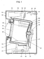
- Fig. 1 shows a sectional view of a drum-type washing machine in the embodiment of the present invention.
- a rotary drum 31 has a cylindrical shape with a bottom.
- a large number of water passage holes 32 are provided on the entire surface of an outer peripheral portion of the rotary drum 31.
- a water tank 33 rotatably incorporates the rotary drum 31.
- An axis of rotation (rotation center axis) 34 passing through a rotation center of the rotary drum 31 is arranged so as to be inclined downward from the front surface side toward the back surface side of the drum-type washing machine.
- a belt 47 is coupled to the axis of rotation 34, and a motor 35 positioned in the vicinity of the back surface side of the water tank 33 is coupled to the belt 47. By driving the motor 35, the rotary drum 31 is driven and rotated in a forward direction or in a reverse direction.
- An inclination angle of the rotary drum 31 and the axis of rotation 34 with respect to the horizontal direction is for example 10 degrees.
- a plurality of wall surface baffles 36 serving as protruding portions for agitating clothing are provided on an inner wall surface of the rotary drum 31 .
- a plurality of bottom surface baffles 46 protruding higher as the bottom surface baffles come closer to the axis of rotation 34 (i.e., the rotation center of the rotary drum 31) are formed.
- the axis of rotation is arranged so as to be inclined downward from the front surface side toward the back surface side is described in the present embodiment.
- the axis of rotation may be horizontally arranged.
- a ring shape projection 52 is formed on the outer peripheral side of an inner bottom surface of the water tank 33.
- a gap between the inner bottom surface of the water tank 33 and an outer bottom surface of the rotary drum 31 is reduced by the ring shape projection 52 to an allowable extent in terms of manufacture.
- a drive shaft flange 51 for improving strength of the rotary drum 31 is fixed on the outer bottom surface side of the rotary drum 31.
- a water tank unit 60 of a vibration system is configured by the rotary drum 31, the drive shaft flange 51, the water tank 33, the motor 35, and the like.
- An opening portion is provided on an upward inclined surface of a washing machine main body 39 positioned on the front opening portion side of the water tank 33, and the opening portion is openably and closably covered by a lid body 37.
- a lid body 37 By opening the lid body 37, a laundry can be taken out and brought into the rotary drum 31 through a clothing outlet/inlet 38 serving as an opening portion provided in the rotary drum 31.
- an anti-vibration member 41 is attached on the lower side, and a spring body 48 is attached on the upper side.
- the water tank unit 60 is oscillatably supported by the anti-vibration member 41 and the spring body 48.
- One end of a drainage passage 42 is connected to a lower part of the water tank 33.
- the other end of the drainage passage 42 is connected to a drainage valve 43.
- a water supply valve 44 is provided on the upper side.
- a water supply passage 45 is connected to the water supply valve 44.
- the water supply passage 45 communicates with the water tank 33 via a detergent case 53 (not shown in Fig. 1 ). Water supplied from the water supply passage 45 enters the detergent case 53, dissolves detergent in the detergent case 53, and enters the water tank 33 as the washing water. In such a way, the water supply valve 44 supplies the washing water into the water tank 33.
- a controller 56 is provided on the upper side.
- the controller 56 controls actions of the motor 35 and the like, and controls each step such as washing, rinsing, and spin-drying.
- the motor 35 configured by a DC brushless motor or the like is controlled by the controller 56, a drive circuit (not shown), and the like in such a manner that forward-reverse rotation is variable and the rotation number is variable.
- an input setting portion 49 for a user to select a washing course or the like and a display portion 50 for displaying a selection result, a progress degree of the steps, an action error, and the like so as to notify the user are provided.
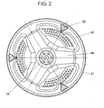
- Fig. 2 is a sectional view to see the bottom surface side of the rotary drum 31 of the drum-type washing machine in the embodiment of the present invention.
- the plurality of wall surface baffles 36 for agitating the clothing are provided on the inner wall surface of the rotary drum 31, and the plurality of bottom surface baffles 46 are provided on the inner bottom surface of the rotary drum 31.
- the wall surface baffles 36 and the bottom surface baffles 46 are alternately arranged on a circumference taking the axis of rotation 34 of the rotary drum 31 as a center.
- Fig. 2 shows a case where the three wall surface baffles 36 and the three bottom surface baffles 46 are provided.
- the number of the wall surface baffles 36 and the number of the bottom surface baffles 46 are not limited to this but can be appropriately set.
- Step S1 After opening the lid body 37, bringing the laundry into the rotary drum 31, and bringing a predetermined amount of detergent into the detergent case 53, the user operates the input setting portion 49 so as to start an operation of the drum-type washing machine.
- a washing step is firstly executed (Step S1).
- the washing water is supplied by activating the water supply valve 44.
- the supplied washing water passes through the water supply passage 45 and the detergent case 53 and enters the water tank 33 together with the detergent.
- the motor 35 is controlled so that rotation speed of the rotary drum 31 is increased to predetermined rotation speed.
- actions of the rotary drum 31 consisting of forward rotation, pause, reverse rotation, and pause serve as one cycle, and repeating the cycle (washing action) is executed for a predetermined time.
- the plurality of wall surface baffles 36 and the bottom surface baffles 46 are alternately arranged on the circumference.
- the laundry positioned on the lower side (laundry positioned in a right lower part of the rotary drum 31 in Fig. 1 ) is pushed upward by the bottom surface baffles 46.
- the laundry pushed upward is moved in the rotation direction by the wall surface baffles 36 and then dropped downward.
- the drum-type washing machine in the present embodiment can three-dimensionally rotate the laundry in the rotary drum 31 so as to efficiently perform the washing action and disperse the laundry without entangling the laundry.
- the laundry is brought up so as to be nipped between the wall surface baffles 36 and the bottom surface baffles 46. Therefore, the laundry is not easily slipped off the wall surface baffles 36 while being brought up by the wall surface baffles 36. After being pushed upward, the laundry is dropped. Thus, a beat-washing effect can be obtained so that a washing performance is improved.
- the bottom surface baffles 46 protrude higher toward the opening portion side of the rotary drum 31 as the bottom surface baffles come closer to a center (axis of rotation 34) of the rotary drum 31.
- Step S2 a first drainage step
- Step S3 a rinsing step
- Step S5 a spin-drying step
- the plurality of wall surface baffles 36 provided on the inner wall surface of the rotary drum 31 and the plurality of bottom surface baffles 46 provided on the inner bottom surface of the rotary drum 31 are alternately arranged on the circumference taking the axis of rotation 34 of the rotary drum 31 as a center.
- the washing machine according to the present invention can disperse the laundry in the rotary drum without entangling the laundry and efficiently perform the washing action and a rinsing action.
- the washing machine can be applied to other washing machines and the like.
Description
- The present invention relates to a drum-type washing machine for washing a laundry in a rotary drum.
- Conventionally, in this type of washing machine, a configuration that baffles are provided in a rotary drum and configurations that an artifice is given to a shape of the baffles or a shape of the rotary drum are proposed in order to disperse a laundry (for example, refer to Patent Literature1).
-
Fig. 3 shows a sectional view of a conventional drum-type washing machine described in Patent Literature 1. - As shown in
Fig. 3 , awater tank 2 supported by a plurality of suspensions (not shown) are arranged in a housing 1. Thewater tank 2 has a substantially cylinder shape axisymmetrical about an axis of rotation. The axis of rotation of thewater tank 2 is inclined forward and upward with respect to the horizontal direction in such a manner that abottom surface portion 4a of thewater tank 2 is lower than anopening portion 2a on a front surface side of thewater tank 2. Adrum 4 having a large number ofholes 3 on a peripheral wall is arranged in thewater tank 2. Thedrum 4 is driven and rotated by adrive device 5 provided in the bottom surface portion of thewater tank 2 such as a motor. Thedrum 4 is rotated in a forward direction or in a reverse direction (i.e., forward-reverse rotation). - At the time of the forward-reverse rotation, clothing A in the
drum 4 is brought up by a plurality ofbaffles 6 provided on the peripheral wall in thedrum 4 and then dropped. Thereby, the clothing A is agitated. Thebaffles 6 extend toward theopening portion 2a from thebottom surface portion 4a in thedrum 4 and protrude inwardly toward the rotation axis thedrum 4. Size of thebaffles 6 is larger on the side of thebottom surface portion 4a than on the side of theopening portion 2a. - When an inner diameter of the
bottom surface portion 4a of thedrum 4 is D1 and an inner diameter of a front surface portion of thedrum 4 is D2, D1 is smaller than D2 (D1 < D2). That is, thedrum 4 has a taper structure that a diameter of the front surface portion is larger than a diameter of the bottom surface portion (i.e., the taper structure that a diameter is larger on the front surface side). - An
auxiliary baffle 21 is provided in thebottom surface portion 4a of thedrum 4. Theauxiliary baffle 21 is continuously connected to bothside surfaces 6a of thebaffles 6 so as to form aninclined surface 21 a spreading toward thebottom surface portion 4a of thedrum 4. In any case of the forward-reverse rotation of thedrum 4, the laundry can be moved to the side of the front surface portion of thedrum 4 by theauxiliary baffle 21. - Patent Literature 1:
JP 2009-22688 A - However, the
drum 4 in the above conventional configuration has the taper structure that the diameter is larger on the front surface side. Thus, when thedrum 4 is rotated, the laundry is easily moved to the front surface side of thedrum 4. Meanwhile, circumferential speed of the drum is high on the side of thebottom surface portion 4a of thedrum 4. Thus, the laundry easily gets entangled (easily gets together). Since the laundry entangled in thebottom surface portion 4a of thedrum 4 is moved to the front surface side of thedrum 4, washing is not efficiently performed. Since the laundry is leaned to one side, an interior of thedrum 4 becomes an imbalance state (unstable state), so that vibration becomes larger at the time of spin-drying. -
JP 2002-315985 A - It is an object of the present invention to provide an improved and useful drum-type washing machine in which the above-mentioned problems are eliminated.
- In order to achieve the above-mentioned object, there is provided a drum-type washing machine according to claim 1.
- Advantageously, a drum-type washing machine includes a rotary drum in which an axis of rotation is horizontally arranged or is arranged so as to be inclined downward from a front surface side toward a back surface side, a water tank rotatably incorporating the rotary drum, and a motor for rotating the rotary drum, wherein the rotary drum has a plurality of wall surface baffles on an inner wall surface and has a plurality of bottom surface baffles on an inner bottom surface;
and the wall surface baffles and the bottom surface baffles are alternately arranged on a circumference taking the axis of rotation as a center. - Thereby, vibration at the time of spin-drying is reduced by efficiently performing an agitation action and dispersing a laundry.
- With the drum-type washing machine of the present invention, the vibration at the time of spin-drying can be reduced by efficiently performing the agitation action and dispersing the laundry.
- These aspects and features of the present invention will become clear from the following description taken in conjunction with the preferred embodiments thereof with reference to the accompanying drawings, in which:
-
Fig. 1 is a sectional view of a drum-type washing machine in an embodiment of the present invention; -
Fig. 2 is a sectional view showing a bottom surface portion of a rotary drum of the same drum-type washing machine; and -
Fig. 3 is a sectional view of a conventional drum-type washing machine. - In a first aspect of the invention, a drum-type washing machine includes a rotary drum in which an axis of rotation is horizontally arranged or is arranged so as to be inclined downward from a front surface side toward a back surface side, a water tank rotatably incorporating the rotary drum, and a motor for rotating the rotary drum, wherein the rotary drum has a plurality of wall surface baffles on an inner wall surface and has a plurality of bottom surface baffles on an inner bottom surface, and the wall surface baffles and the bottom surface baffles are alternately arranged on a circumference taking the axis of rotation as a center. With such a configuration, vibration at the time of spin-drying can be reduced by efficiently performing an agitation action and dispersing a laundry.
- In a second aspect of the invention, the bottom surface baffles protrude higher as the bottom surface baffles come closer to the axis of rotation of the rotary drum in the drum-type washing machine of the first aspect of the invention. With such a configuration, the laundry is pushed to the opening portion side of the rotary drum and dispersed.
- Before the description of the present invention proceeds, it is to be noted that like parts are designated by like reference numerals throughout the accompanying drawings. Hereinbelow, embodiments of the present invention will be described with reference to the accompanying drawings. It should be noted that the present invention is not limited to this embodiment.
-
Fig. 1 shows a sectional view of a drum-type washing machine in the embodiment of the present invention. - As shown in
Fig. 1 , arotary drum 31 has a cylindrical shape with a bottom. A large number ofwater passage holes 32 are provided on the entire surface of an outer peripheral portion of therotary drum 31. Awater tank 33 rotatably incorporates therotary drum 31. An axis of rotation (rotation center axis) 34 passing through a rotation center of therotary drum 31 is arranged so as to be inclined downward from the front surface side toward the back surface side of the drum-type washing machine. Abelt 47 is coupled to the axis ofrotation 34, and amotor 35 positioned in the vicinity of the back surface side of thewater tank 33 is coupled to thebelt 47. By driving themotor 35, therotary drum 31 is driven and rotated in a forward direction or in a reverse direction. An inclination angle of therotary drum 31 and the axis ofrotation 34 with respect to the horizontal direction is for example 10 degrees. On an inner wall surface of therotary drum 31, a plurality ofwall surface baffles 36 serving as protruding portions for agitating clothing are provided. On aninner bottom surface 40 of therotary drum 31, a plurality ofbottom surface baffles 46 protruding higher as the bottom surface baffles come closer to the axis of rotation 34 (i.e., the rotation center of the rotary drum 31) are formed. It should be noted that a case where the axis of rotation is arranged so as to be inclined downward from the front surface side toward the back surface side is described in the present embodiment. However, the axis of rotation may be horizontally arranged. - On the outer peripheral side of an inner bottom surface of the
water tank 33, aring shape projection 52 is formed. A gap between the inner bottom surface of thewater tank 33 and an outer bottom surface of therotary drum 31 is reduced by thering shape projection 52 to an allowable extent in terms of manufacture. Thereby, wind flow speed at the time of spin-drying rotation is increased, and pressure (sound pressure) is lowered. Therefore, wind noise is reduced. - A
drive shaft flange 51 for improving strength of therotary drum 31 is fixed on the outer bottom surface side of therotary drum 31. - A
water tank unit 60 of a vibration system is configured by therotary drum 31, thedrive shaft flange 51, thewater tank 33, themotor 35, and the like. - An opening portion is provided on an upward inclined surface of a washing machine
main body 39 positioned on the front opening portion side of thewater tank 33, and the opening portion is openably and closably covered by alid body 37. By opening thelid body 37, a laundry can be taken out and brought into therotary drum 31 through a clothing outlet/inlet 38 serving as an opening portion provided in therotary drum 31. - In the washing machine
main body 39, ananti-vibration member 41 is attached on the lower side, and aspring body 48 is attached on the upper side. Thewater tank unit 60 is oscillatably supported by theanti-vibration member 41 and thespring body 48. - One end of a
drainage passage 42 is connected to a lower part of thewater tank 33. The other end of thedrainage passage 42 is connected to adrainage valve 43. By connecting thedrainage passage 42 in such a way, washing water in thewater tank 33 is drained to an exterior of the drum-type washing machine. - In the washing machine
main body 39, awater supply valve 44 is provided on the upper side. Awater supply passage 45 is connected to thewater supply valve 44. Thewater supply passage 45 communicates with thewater tank 33 via a detergent case 53 (not shown inFig. 1 ). Water supplied from thewater supply passage 45 enters thedetergent case 53, dissolves detergent in thedetergent case 53, and enters thewater tank 33 as the washing water. In such a way, thewater supply valve 44 supplies the washing water into thewater tank 33. - In the washing machine
main body 39, acontroller 56 is provided on the upper side. Thecontroller 56 controls actions of themotor 35 and the like, and controls each step such as washing, rinsing, and spin-drying. - The
motor 35 configured by a DC brushless motor or the like is controlled by thecontroller 56, a drive circuit (not shown), and the like in such a manner that forward-reverse rotation is variable and the rotation number is variable. - In an upper part of a front surface of the washing machine
main body 39, aninput setting portion 49 for a user to select a washing course or the like and adisplay portion 50 for displaying a selection result, a progress degree of the steps, an action error, and the like so as to notify the user are provided. -
Fig. 2 is a sectional view to see the bottom surface side of therotary drum 31 of the drum-type washing machine in the embodiment of the present invention. - In
Fig. 2 , as described above, the plurality of wall surface baffles 36 for agitating the clothing are provided on the inner wall surface of therotary drum 31, and the plurality of bottom surface baffles 46 are provided on the inner bottom surface of therotary drum 31. The wall surface baffles 36 and the bottom surface baffles 46 are alternately arranged on a circumference taking the axis ofrotation 34 of therotary drum 31 as a center.Fig. 2 shows a case where the three wall surface baffles 36 and the three bottom surface baffles 46 are provided. However, the number of the wall surface baffles 36 and the number of the bottom surface baffles 46 are not limited to this but can be appropriately set. - Actions and operations of the drum-type washing machine configured as above will be described below.
- After opening the
lid body 37, bringing the laundry into therotary drum 31, and bringing a predetermined amount of detergent into thedetergent case 53, the user operates theinput setting portion 49 so as to start an operation of the drum-type washing machine. When the operation is started, a washing step is firstly executed (Step S1). - In the washing step, the washing water is supplied by activating the
water supply valve 44. The supplied washing water passes through thewater supply passage 45 and thedetergent case 53 and enters thewater tank 33 together with the detergent. After the washing water is supplied to a predetermined water level, themotor 35 is controlled so that rotation speed of therotary drum 31 is increased to predetermined rotation speed. After that, actions of therotary drum 31 consisting of forward rotation, pause, reverse rotation, and pause serve as one cycle, and repeating the cycle (washing action) is executed for a predetermined time. - It should be noted that the plurality of wall surface baffles 36 and the bottom surface baffles 46 are alternately arranged on the circumference. Thus, as the
rotary drum 31 is rotated, the laundry positioned on the lower side (laundry positioned in a right lower part of therotary drum 31 inFig. 1 ) is pushed upward by the bottom surface baffles 46. The laundry pushed upward is moved in the rotation direction by the wall surface baffles 36 and then dropped downward. By repeating this action, the drum-type washing machine in the present embodiment can three-dimensionally rotate the laundry in therotary drum 31 so as to efficiently perform the washing action and disperse the laundry without entangling the laundry. - The laundry is brought up so as to be nipped between the wall surface baffles 36 and the bottom surface baffles 46. Therefore, the laundry is not easily slipped off the wall surface baffles 36 while being brought up by the wall surface baffles 36. After being pushed upward, the laundry is dropped. Thus, a beat-washing effect can be obtained so that a washing performance is improved.
- The bottom surface baffles 46 protrude higher toward the opening portion side of the
rotary drum 31 as the bottom surface baffles come closer to a center (axis of rotation 34) of therotary drum 31. Thus, there is an effect of pushing the laundry to the opening portion side (front surface side) of therotary drum 31 and dispersing the laundry when the laundry reaches the upper side by rotation of therotary drum 31. - After this washing action for a predetermined time, the washing step is finished. Next, a first drainage step (Step S2) is executed. After the first drainage step is executed, a rinsing step (Step S3) is executed. Also in the rinsing step, the same washing action as the washing step is performed. After that, a drainage step (Step S4) and a spin-drying step (Step S5) are executed.
- As described above, in the drum-type washing machine according to the present embodiment, the plurality of wall surface baffles 36 provided on the inner wall surface of the
rotary drum 31 and the plurality of bottom surface baffles 46 provided on the inner bottom surface of therotary drum 31 are alternately arranged on the circumference taking the axis ofrotation 34 of therotary drum 31 as a center. By such arrangement, at the time of the washing step or the rinsing step, the laundry is not easily entangled and the laundry is three-dimensionally rotated in therotary drum 31, so that an agitation action is efficiently performed. Therefore, the washing performance and a rinsing performance are improved, and the laundry is dispersed. By dispersing the laundry, vibration and noise are reduced at the time of spin-drying. - It is to be noted that, by properly combining the arbitrary embodiments of the aforementioned various embodiments, the effects possessed by them can be produced.
- As described above, the washing machine according to the present invention can disperse the laundry in the rotary drum without entangling the laundry and efficiently perform the washing action and a rinsing action. Thus, the washing machine can be applied to other washing machines and the like.
- Although the present invention has been fully described in connection with the preferred embodiment thereof with reference to the accompanying drawings, it is to be noted that various changes and modifications are apparent to those skilled in the art.
-
- 31:
- ROTARY DRUM
- 33:
- WATER TANK
- 34:
- AXIS OF ROTATION (ROTATION CENTER AXIS)
- 35:
- MOTOR
- 36:
- WALL SURFACE BAFFLE
- 39:
- WASHING MACHINE MAIN BODY
- 46:
- BOTTOM SURFACE BAFFLE
- 56:
- CONTROLLER
- 37.
- LID BODY
- 40.
- INNER BOTTOM SURFACE
- 42.
- DRAINAGE PASSAGE
- 43.
- DRAINAGE VALVE
- 44.
- WATER SUPPLY VALVE
- 45.
- WATER SUPPLY PASSAGE
- 47.
- BELT
- 48.
- SPRING BODY
- 49.
- INPUT SETTING PORTION
- 50.
- DISPLAY PORTION
- 51.
- DRIVE SHAFT FLANGE
- 52.
- RING SHAPE PROJECTION
- 53.
- DETERGENT CASE
- 60.
- WATER TANK UNIT
Claims (1)
- A drum-type washing machine, comprising:a rotary drum (31) in which an axis of rotation (34) is horizontally arranged or is arranged so as to be inclined downward from a front surface side toward a back surface side;a water tank (33) rotatably incorporating the rotary drum (31); anda motor (35) for rotating the rotary drum (31); whereinthe rotary drum (31) has a plurality of wall surface baffles (36) on an inner wall surface and has a plurality of bottom surface baffles (46) on an inner bottom surface (40);the wall surface baffles (36) and the bottom surface baffles (46) are alternately arranged on a circumference taking the axis of rotation (34) as a center,characterized in that the bottom surface baffles (46) form a continuous inclined surface starting from the axis of rotation (34) of the rotary drum (31) and extending toward its inner bottom surface (40) and protrude higher as the bottom surface baffles (46) come closer to the axis of rotation (34) of the rotary drum (31).
Applications Claiming Priority (2)
| Application Number | Priority Date | Filing Date | Title |
|---|---|---|---|
| JP2011036735A JP2012170680A (en) | 2011-02-23 | 2011-02-23 | Drum-type washing machine |
| PCT/JP2012/001204 WO2012114741A1 (en) | 2011-02-23 | 2012-02-22 | Drum-type washing machine |
Publications (3)
| Publication Number | Publication Date |
|---|---|
| EP2562301A1 EP2562301A1 (en) | 2013-02-27 |
| EP2562301A4 EP2562301A4 (en) | 2013-09-25 |
| EP2562301B1 true EP2562301B1 (en) | 2014-12-31 |
Family
ID=46720533
Family Applications (1)
| Application Number | Title | Priority Date | Filing Date |
|---|---|---|---|
| EP12749539.8A Not-in-force EP2562301B1 (en) | 2011-02-23 | 2012-02-22 | Drum-type washing machine |
Country Status (5)
| Country | Link |
|---|---|
| US (1) | US20130025332A1 (en) |
| EP (1) | EP2562301B1 (en) |
| JP (1) | JP2012170680A (en) |
| CN (1) | CN102812174A (en) |
| WO (1) | WO2012114741A1 (en) |
Families Citing this family (4)
| Publication number | Priority date | Publication date | Assignee | Title |
|---|---|---|---|---|
| JP2014064727A (en) * | 2012-09-26 | 2014-04-17 | Hitachi Appliances Inc | Drum type washing machine and drum type washing and drying machine |
| JP6140022B2 (en) * | 2013-07-26 | 2017-05-31 | シャープ株式会社 | Washing machine |
| US20160258098A1 (en) * | 2015-03-06 | 2016-09-08 | Hg LAUNDRY SYSTEMS, LLC | Combination washer/dryer apparatus |
| CN107893261A (en) * | 2017-12-21 | 2018-04-10 | 徐州腾宇羽绒制品设备有限公司 | Tilt shampooer |
Family Cites Families (14)
| Publication number | Priority date | Publication date | Assignee | Title |
|---|---|---|---|---|
| JPS47146Y1 (en) * | 1968-07-05 | 1972-01-06 | ||
| DE4021533A1 (en) * | 1990-07-06 | 1992-01-09 | Bauknecht Hausgeraete | Dryer incorporates horizontal revolving cylindrical drum - at least one drum end features projection extending into drum |
| JPH07116393A (en) * | 1993-10-22 | 1995-05-09 | Matsushita Electric Ind Co Ltd | Clothes dryer |
| JPH09215894A (en) * | 1996-02-15 | 1997-08-19 | Matsushita Electric Ind Co Ltd | Washing machine |
| JP3877543B2 (en) * | 2001-04-20 | 2007-02-07 | 三洋電機株式会社 | Drum washing machine |
| KR101054408B1 (en) * | 2004-04-19 | 2011-08-05 | 엘지전자 주식회사 | washer |
| JP2006223452A (en) * | 2005-02-16 | 2006-08-31 | Toshiba Corp | Drum type washing machine |
| KR101253566B1 (en) * | 2005-07-07 | 2013-04-11 | 삼성전자주식회사 | Drum type washing machine |
| JP4566112B2 (en) * | 2005-10-27 | 2010-10-20 | 三洋電機株式会社 | Clothes dryer |
| JP4275160B2 (en) * | 2006-08-24 | 2009-06-10 | 三洋電機株式会社 | Drum washing machine |
| JP4893229B2 (en) * | 2006-10-26 | 2012-03-07 | パナソニック株式会社 | Drum washing machine |
| JP2009022688A (en) * | 2007-07-24 | 2009-02-05 | Panasonic Corp | Drum type washing/drying machine |
| JP4713620B2 (en) * | 2008-09-05 | 2011-06-29 | 日立アプライアンス株式会社 | Washing and drying machine |
| JP2011036735A (en) | 2009-08-06 | 2011-02-24 | Panasonic Electric Works Co Ltd | Electrostatic atomization apparatus |
-
2011
- 2011-02-23 JP JP2011036735A patent/JP2012170680A/en active Pending
-
2012
- 2012-02-22 WO PCT/JP2012/001204 patent/WO2012114741A1/en active Application Filing
- 2012-02-22 CN CN2012800009486A patent/CN102812174A/en active Pending
- 2012-02-22 EP EP12749539.8A patent/EP2562301B1/en not_active Not-in-force
- 2012-02-22 US US13/638,251 patent/US20130025332A1/en not_active Abandoned
Also Published As
| Publication number | Publication date |
|---|---|
| EP2562301A1 (en) | 2013-02-27 |
| EP2562301A4 (en) | 2013-09-25 |
| JP2012170680A (en) | 2012-09-10 |
| WO2012114741A1 (en) | 2012-08-30 |
| US20130025332A1 (en) | 2013-01-31 |
| CN102812174A (en) | 2012-12-05 |
Similar Documents
| Publication | Publication Date | Title |
|---|---|---|
| US20140026624A1 (en) | Washing apparatus | |
| EP2562301B1 (en) | Drum-type washing machine | |
| JP4710539B2 (en) | Drum washing machine | |
| US20140283563A1 (en) | Fully automatic washing machine | |
| JP2008055016A (en) | Drum type washing machine | |
| CN101838914B (en) | Clothes washing method and clothes washing machine | |
| JP2015223318A (en) | Washing machine | |
| KR20050087342A (en) | Inclined drum-type washing machine with pulsator and washing method in washing machine | |
| JP2010187722A (en) | Washing machine | |
| JP6356496B2 (en) | Drum washing machine | |
| JP2011139771A (en) | Washing machine | |
| KR20130037411A (en) | Washing machine having impeller | |
| JP6235200B2 (en) | Washing machine | |
| JP3802316B2 (en) | Washing machine | |
| JP2006223452A (en) | Drum type washing machine | |
| JP7292640B2 (en) | vertical washing machine | |
| JP2019097866A (en) | Drum type washing machine | |
| JP2016000168A (en) | Drum type washing machine | |
| JP6385146B2 (en) | Drum washing machine | |
| JP7344633B2 (en) | washing machine | |
| JP7285393B2 (en) | drum washing machine | |
| JP2006075478A (en) | Drum type washing machine | |
| KR102317045B1 (en) | Control Method for Laundry Treating Apparatus | |
| KR20100053946A (en) | A controlling method for a washing machine | |
| JP6509503B2 (en) | Drum type washing machine |
Legal Events
| Date | Code | Title | Description |
|---|---|---|---|
| PUAI | Public reference made under article 153(3) epc to a published international application that has entered the european phase |
Free format text: ORIGINAL CODE: 0009012 |
|
| 17P | Request for examination filed |
Effective date: 20120925 |
|
| AK | Designated contracting states |
Kind code of ref document: A1 Designated state(s): AL AT BE BG CH CY CZ DE DK EE ES FI FR GB GR HR HU IE IS IT LI LT LU LV MC MK MT NL NO PL PT RO RS SE SI SK SM TR |
|
| A4 | Supplementary search report drawn up and despatched |
Effective date: 20130826 |
|
| RIC1 | Information provided on ipc code assigned before grant |
Ipc: D06F 23/02 20060101ALI20130820BHEP Ipc: D06F 37/06 20060101AFI20130820BHEP Ipc: D06F 23/06 20060101ALI20130820BHEP Ipc: D06F 39/12 20060101ALI20130820BHEP |
|
| 17Q | First examination report despatched |
Effective date: 20140313 |
|
| DAX | Request for extension of the european patent (deleted) | ||
| GRAP | Despatch of communication of intention to grant a patent |
Free format text: ORIGINAL CODE: EPIDOSNIGR1 |
|
| INTG | Intention to grant announced |
Effective date: 20140916 |
|
| GRAS | Grant fee paid |
Free format text: ORIGINAL CODE: EPIDOSNIGR3 |
|
| GRAA | (expected) grant |
Free format text: ORIGINAL CODE: 0009210 |
|
| AK | Designated contracting states |
Kind code of ref document: B1 Designated state(s): AL AT BE BG CH CY CZ DE DK EE ES FI FR GB GR HR HU IE IS IT LI LT LU LV MC MK MT NL NO PL PT RO RS SE SI SK SM TR |
|
| REG | Reference to a national code |
Ref country code: CH Ref legal event code: EP Ref country code: GB Ref legal event code: FG4D |
|
| REG | Reference to a national code |
Ref country code: IE Ref legal event code: FG4D |
|
| REG | Reference to a national code |
Ref country code: AT Ref legal event code: REF Ref document number: 704485 Country of ref document: AT Kind code of ref document: T Effective date: 20150215 |
|
| REG | Reference to a national code |
Ref country code: DE Ref legal event code: R096 Ref document number: 602012004682 Country of ref document: DE Effective date: 20150219 |
|
| PG25 | Lapsed in a contracting state [announced via postgrant information from national office to epo] |
Ref country code: FI Free format text: LAPSE BECAUSE OF FAILURE TO SUBMIT A TRANSLATION OF THE DESCRIPTION OR TO PAY THE FEE WITHIN THE PRESCRIBED TIME-LIMIT Effective date: 20141231 Ref country code: LT Free format text: LAPSE BECAUSE OF FAILURE TO SUBMIT A TRANSLATION OF THE DESCRIPTION OR TO PAY THE FEE WITHIN THE PRESCRIBED TIME-LIMIT Effective date: 20141231 Ref country code: NO Free format text: LAPSE BECAUSE OF FAILURE TO SUBMIT A TRANSLATION OF THE DESCRIPTION OR TO PAY THE FEE WITHIN THE PRESCRIBED TIME-LIMIT Effective date: 20150331 |
|
| REG | Reference to a national code |
Ref country code: NL Ref legal event code: VDEP Effective date: 20141231 |
|
| REG | Reference to a national code |
Ref country code: LT Ref legal event code: MG4D |
|
| PG25 | Lapsed in a contracting state [announced via postgrant information from national office to epo] |
Ref country code: SE Free format text: LAPSE BECAUSE OF FAILURE TO SUBMIT A TRANSLATION OF THE DESCRIPTION OR TO PAY THE FEE WITHIN THE PRESCRIBED TIME-LIMIT Effective date: 20141231 Ref country code: LV Free format text: LAPSE BECAUSE OF FAILURE TO SUBMIT A TRANSLATION OF THE DESCRIPTION OR TO PAY THE FEE WITHIN THE PRESCRIBED TIME-LIMIT Effective date: 20141231 Ref country code: RS Free format text: LAPSE BECAUSE OF FAILURE TO SUBMIT A TRANSLATION OF THE DESCRIPTION OR TO PAY THE FEE WITHIN THE PRESCRIBED TIME-LIMIT Effective date: 20141231 Ref country code: HR Free format text: LAPSE BECAUSE OF FAILURE TO SUBMIT A TRANSLATION OF THE DESCRIPTION OR TO PAY THE FEE WITHIN THE PRESCRIBED TIME-LIMIT Effective date: 20141231 Ref country code: GR Free format text: LAPSE BECAUSE OF FAILURE TO SUBMIT A TRANSLATION OF THE DESCRIPTION OR TO PAY THE FEE WITHIN THE PRESCRIBED TIME-LIMIT Effective date: 20150401 |
|
| REG | Reference to a national code |
Ref country code: AT Ref legal event code: MK05 Ref document number: 704485 Country of ref document: AT Kind code of ref document: T Effective date: 20141231 |
|
| PG25 | Lapsed in a contracting state [announced via postgrant information from national office to epo] |
Ref country code: NL Free format text: LAPSE BECAUSE OF FAILURE TO SUBMIT A TRANSLATION OF THE DESCRIPTION OR TO PAY THE FEE WITHIN THE PRESCRIBED TIME-LIMIT Effective date: 20141231 |
|
| PG25 | Lapsed in a contracting state [announced via postgrant information from national office to epo] |
Ref country code: RO Free format text: LAPSE BECAUSE OF FAILURE TO SUBMIT A TRANSLATION OF THE DESCRIPTION OR TO PAY THE FEE WITHIN THE PRESCRIBED TIME-LIMIT Effective date: 20141231 Ref country code: CZ Free format text: LAPSE BECAUSE OF FAILURE TO SUBMIT A TRANSLATION OF THE DESCRIPTION OR TO PAY THE FEE WITHIN THE PRESCRIBED TIME-LIMIT Effective date: 20141231 Ref country code: SK Free format text: LAPSE BECAUSE OF FAILURE TO SUBMIT A TRANSLATION OF THE DESCRIPTION OR TO PAY THE FEE WITHIN THE PRESCRIBED TIME-LIMIT Effective date: 20141231 Ref country code: ES Free format text: LAPSE BECAUSE OF FAILURE TO SUBMIT A TRANSLATION OF THE DESCRIPTION OR TO PAY THE FEE WITHIN THE PRESCRIBED TIME-LIMIT Effective date: 20141231 |
|
| PG25 | Lapsed in a contracting state [announced via postgrant information from national office to epo] |
Ref country code: AT Free format text: LAPSE BECAUSE OF FAILURE TO SUBMIT A TRANSLATION OF THE DESCRIPTION OR TO PAY THE FEE WITHIN THE PRESCRIBED TIME-LIMIT Effective date: 20141231 Ref country code: PL Free format text: LAPSE BECAUSE OF FAILURE TO SUBMIT A TRANSLATION OF THE DESCRIPTION OR TO PAY THE FEE WITHIN THE PRESCRIBED TIME-LIMIT Effective date: 20141231 Ref country code: IS Free format text: LAPSE BECAUSE OF FAILURE TO SUBMIT A TRANSLATION OF THE DESCRIPTION OR TO PAY THE FEE WITHIN THE PRESCRIBED TIME-LIMIT Effective date: 20150430 |
|
| PG25 | Lapsed in a contracting state [announced via postgrant information from national office to epo] |
Ref country code: LU Free format text: LAPSE BECAUSE OF FAILURE TO SUBMIT A TRANSLATION OF THE DESCRIPTION OR TO PAY THE FEE WITHIN THE PRESCRIBED TIME-LIMIT Effective date: 20150222 |
|
| REG | Reference to a national code |
Ref country code: CH Ref legal event code: PL |
|
| REG | Reference to a national code |
Ref country code: DE Ref legal event code: R097 Ref document number: 602012004682 Country of ref document: DE |
|
| PG25 | Lapsed in a contracting state [announced via postgrant information from national office to epo] |
Ref country code: CH Free format text: LAPSE BECAUSE OF NON-PAYMENT OF DUE FEES Effective date: 20150228 Ref country code: EE Free format text: LAPSE BECAUSE OF FAILURE TO SUBMIT A TRANSLATION OF THE DESCRIPTION OR TO PAY THE FEE WITHIN THE PRESCRIBED TIME-LIMIT Effective date: 20141231 Ref country code: MC Free format text: LAPSE BECAUSE OF FAILURE TO SUBMIT A TRANSLATION OF THE DESCRIPTION OR TO PAY THE FEE WITHIN THE PRESCRIBED TIME-LIMIT Effective date: 20141231 Ref country code: LI Free format text: LAPSE BECAUSE OF NON-PAYMENT OF DUE FEES Effective date: 20150228 Ref country code: DK Free format text: LAPSE BECAUSE OF FAILURE TO SUBMIT A TRANSLATION OF THE DESCRIPTION OR TO PAY THE FEE WITHIN THE PRESCRIBED TIME-LIMIT Effective date: 20141231 |
|
| PLBE | No opposition filed within time limit |
Free format text: ORIGINAL CODE: 0009261 |
|
| STAA | Information on the status of an ep patent application or granted ep patent |
Free format text: STATUS: NO OPPOSITION FILED WITHIN TIME LIMIT |
|
| REG | Reference to a national code |
Ref country code: IE Ref legal event code: MM4A |
|
| 26N | No opposition filed |
Effective date: 20151001 |
|
| PG25 | Lapsed in a contracting state [announced via postgrant information from national office to epo] |
Ref country code: IT Free format text: LAPSE BECAUSE OF FAILURE TO SUBMIT A TRANSLATION OF THE DESCRIPTION OR TO PAY THE FEE WITHIN THE PRESCRIBED TIME-LIMIT Effective date: 20141231 |
|
| PG25 | Lapsed in a contracting state [announced via postgrant information from national office to epo] |
Ref country code: IE Free format text: LAPSE BECAUSE OF NON-PAYMENT OF DUE FEES Effective date: 20150222 |
|
| REG | Reference to a national code |
Ref country code: FR Ref legal event code: PLFP Year of fee payment: 5 |
|
| PG25 | Lapsed in a contracting state [announced via postgrant information from national office to epo] |
Ref country code: SI Free format text: LAPSE BECAUSE OF FAILURE TO SUBMIT A TRANSLATION OF THE DESCRIPTION OR TO PAY THE FEE WITHIN THE PRESCRIBED TIME-LIMIT Effective date: 20141231 |
|
| PG25 | Lapsed in a contracting state [announced via postgrant information from national office to epo] |
Ref country code: BE Free format text: LAPSE BECAUSE OF FAILURE TO SUBMIT A TRANSLATION OF THE DESCRIPTION OR TO PAY THE FEE WITHIN THE PRESCRIBED TIME-LIMIT Effective date: 20141231 |
|
| PGFP | Annual fee paid to national office [announced via postgrant information from national office to epo] |
Ref country code: FR Payment date: 20160218 Year of fee payment: 5 |
|
| PG25 | Lapsed in a contracting state [announced via postgrant information from national office to epo] |
Ref country code: MT Free format text: LAPSE BECAUSE OF FAILURE TO SUBMIT A TRANSLATION OF THE DESCRIPTION OR TO PAY THE FEE WITHIN THE PRESCRIBED TIME-LIMIT Effective date: 20141231 |
|
| PG25 | Lapsed in a contracting state [announced via postgrant information from national office to epo] |
Ref country code: BG Free format text: LAPSE BECAUSE OF FAILURE TO SUBMIT A TRANSLATION OF THE DESCRIPTION OR TO PAY THE FEE WITHIN THE PRESCRIBED TIME-LIMIT Effective date: 20141231 Ref country code: SM Free format text: LAPSE BECAUSE OF FAILURE TO SUBMIT A TRANSLATION OF THE DESCRIPTION OR TO PAY THE FEE WITHIN THE PRESCRIBED TIME-LIMIT Effective date: 20141231 Ref country code: HU Free format text: LAPSE BECAUSE OF FAILURE TO SUBMIT A TRANSLATION OF THE DESCRIPTION OR TO PAY THE FEE WITHIN THE PRESCRIBED TIME-LIMIT; INVALID AB INITIO Effective date: 20120222 |
|
| PG25 | Lapsed in a contracting state [announced via postgrant information from national office to epo] |
Ref country code: CY Free format text: LAPSE BECAUSE OF FAILURE TO SUBMIT A TRANSLATION OF THE DESCRIPTION OR TO PAY THE FEE WITHIN THE PRESCRIBED TIME-LIMIT Effective date: 20141231 |
|
| PG25 | Lapsed in a contracting state [announced via postgrant information from national office to epo] |
Ref country code: PT Free format text: LAPSE BECAUSE OF FAILURE TO SUBMIT A TRANSLATION OF THE DESCRIPTION OR TO PAY THE FEE WITHIN THE PRESCRIBED TIME-LIMIT Effective date: 20150501 |
|
| PG25 | Lapsed in a contracting state [announced via postgrant information from national office to epo] |
Ref country code: TR Free format text: LAPSE BECAUSE OF FAILURE TO SUBMIT A TRANSLATION OF THE DESCRIPTION OR TO PAY THE FEE WITHIN THE PRESCRIBED TIME-LIMIT Effective date: 20141231 |
|
| REG | Reference to a national code |
Ref country code: FR Ref legal event code: ST Effective date: 20171031 |
|
| PG25 | Lapsed in a contracting state [announced via postgrant information from national office to epo] |
Ref country code: FR Free format text: LAPSE BECAUSE OF NON-PAYMENT OF DUE FEES Effective date: 20170228 |
|
| PGFP | Annual fee paid to national office [announced via postgrant information from national office to epo] |
Ref country code: GB Payment date: 20180216 Year of fee payment: 7 |
|
| PG25 | Lapsed in a contracting state [announced via postgrant information from national office to epo] |
Ref country code: MK Free format text: LAPSE BECAUSE OF FAILURE TO SUBMIT A TRANSLATION OF THE DESCRIPTION OR TO PAY THE FEE WITHIN THE PRESCRIBED TIME-LIMIT Effective date: 20141231 |
|
| PG25 | Lapsed in a contracting state [announced via postgrant information from national office to epo] |
Ref country code: AL Free format text: LAPSE BECAUSE OF FAILURE TO SUBMIT A TRANSLATION OF THE DESCRIPTION OR TO PAY THE FEE WITHIN THE PRESCRIBED TIME-LIMIT Effective date: 20141231 |
|
| PGFP | Annual fee paid to national office [announced via postgrant information from national office to epo] |
Ref country code: DE Payment date: 20190219 Year of fee payment: 8 |
|
| GBPC | Gb: european patent ceased through non-payment of renewal fee |
Effective date: 20190222 |
|
| PG25 | Lapsed in a contracting state [announced via postgrant information from national office to epo] |
Ref country code: GB Free format text: LAPSE BECAUSE OF NON-PAYMENT OF DUE FEES Effective date: 20190222 |
|
| REG | Reference to a national code |
Ref country code: DE Ref legal event code: R119 Ref document number: 602012004682 Country of ref document: DE |
|
| PG25 | Lapsed in a contracting state [announced via postgrant information from national office to epo] |
Ref country code: DE Free format text: LAPSE BECAUSE OF NON-PAYMENT OF DUE FEES Effective date: 20200901 |