WO2012111797A1 - 空気調和機 - Google Patents
空気調和機 Download PDFInfo
- Publication number
- WO2012111797A1 WO2012111797A1 PCT/JP2012/053799 JP2012053799W WO2012111797A1 WO 2012111797 A1 WO2012111797 A1 WO 2012111797A1 JP 2012053799 W JP2012053799 W JP 2012053799W WO 2012111797 A1 WO2012111797 A1 WO 2012111797A1
- Authority
- WO
- WIPO (PCT)
- Prior art keywords
- motor
- motor cover
- locking
- restricting
- piece
- Prior art date
- Legal status (The legal status is an assumption and is not a legal conclusion. Google has not performed a legal analysis and makes no representation as to the accuracy of the status listed.)
- Ceased
Links
Images










Classifications
-
- F—MECHANICAL ENGINEERING; LIGHTING; HEATING; WEAPONS; BLASTING
- F24—HEATING; RANGES; VENTILATING
- F24F—AIR-CONDITIONING; AIR-HUMIDIFICATION; VENTILATION; USE OF AIR CURRENTS FOR SCREENING
- F24F1/00—Room units for air-conditioning, e.g. separate or self-contained units or units receiving primary air from a central station
- F24F1/0007—Indoor units, e.g. fan coil units
- F24F1/0018—Indoor units, e.g. fan coil units characterised by fans
-
- F—MECHANICAL ENGINEERING; LIGHTING; HEATING; WEAPONS; BLASTING
- F24—HEATING; RANGES; VENTILATING
- F24F—AIR-CONDITIONING; AIR-HUMIDIFICATION; VENTILATION; USE OF AIR CURRENTS FOR SCREENING
- F24F13/00—Details common to, or for air-conditioning, air-humidification, ventilation or use of air currents for screening
- F24F13/20—Casings or covers
- F24F2013/205—Mounting a ventilator fan therein
Definitions
- the present invention relates to a blower fan and an air conditioner equipped with the fan motor.
- the blower fan or fan is used to remove the blower fan from the inside of the housing.
- the motor is detachably mounted in the housing (see Patent Documents 1 to 4).
- the air conditioner of Patent Document 4 includes a bearing that pivotally supports one end of a cross flow fan (cross flow fan), and a motor cover that is attached to the motor receiving portion via a fixing screw and sandwiches the fan motor. By removing the fixing screw of the cover, the fan motor can be removed from the motor receiving portion.
- a cross flow fan cross flow fan
- the fan motor of the blower fan is housed in a motor housing portion surrounded by a motor receiving portion and a motor cover on the housing side. At that time, vibration generated when the fan motor is driven is transmitted to the housing side. In order to prevent this, it is detachably attached to the motor housing portion via a vibration isolating material such as a vibration isolating rubber.
- the motor receiving part and the motor cover that constitute the motor housing part are firmly fixed by screws and screws to prevent vibration from the fan motor from being transmitted to the housing side. There is a problem that it is necessary to release the tightening of the screw or the screw, and the workability is deteriorated.
- the vibration generated by the fan motor is likely to be transmitted to the housing side when using the air conditioner, which may cause unpleasant noise.
- an object of the present invention is to provide an air conditioner capable of improving workability during maintenance and preventing the motor cover from being detached due to vibration and impact during transportation.
- the present invention provides a blower fan that is detachably disposed in a housing, a fan motor thereof, and a motor receiving portion on the housing side so as to face both ends of the fan motor in the motor axial direction.
- a motor cover that covers a part of the surface and a part of the outer peripheral surface of the fan motor, and the motor cover opens and closes to the motor receiving portion via a rotating shaft parallel to the motor shaft of the fan motor.
- the second end is movably supported, and the other end is detachably locked to the motor receiving portion via a locking portion, and restricts movement of the rotating shaft in the axial direction on one end side of the motor cover. 1 restriction part is provided.
- the motor cover faces the motor receiving portion on the housing side, covers both end surfaces of the fan motor in the axial direction of the motor and a part of the outer peripheral surface of the fan motor, and the locking portion is the motor receiving portion.
- the movement of the fan motor is restricted because it is locked in place, but the axis of the rotating shaft on the one end side of the motor cover even if the locking part is released due to vibration or impact during transportation of the air conditioner Since the movement in the direction is restricted by the first restricting portion, the rotation shaft can be prevented from moving in the axial direction without using screws, screws or the like.
- a restricting piece that protrudes toward one end of the motor cover and a restricting hole into which the restricting piece is inserted when the motor cover is rotated around the turning shaft are provided.
- a structure is mentioned and the movement to the rotation-axis direction of the said motor cover is controlled by the insertion attitude
- the movement of the motor cover in the rotational axis direction is restricted by a simple configuration in which the restriction piece protruding to one end side of the motor cover is inserted into the restriction hole on the motor receiving portion side.
- the restricting piece comes out of the restricting hole when the motor cover is pivoted open.
- the latching portion is exemplified by a configuration including a latching piece that can be elastically deformed at the other end of the motor cover, and a latching receiver on the housing side that deforms and latches the latching piece.
- the shape of the locking piece is not particularly limited, and examples thereof include a U-shaped curved shape.
- Such a locking portion can be provided with a second restricting portion that restricts elastic deformation of the locking piece and prevents the locking piece from being detached from the locking receiver.
- the second restricting portion restricts the other end of the motor cover from moving after the other end of the motor cover is locked by the locking portion. That is, since the other end portion of the motor cover is locked to the motor receiving portion by the elastic deformation of the locking portion, the motor cover is prevented from being detached from the motor receiving portion by restricting the elastic deformation.
- the second restricting portion is constituted by a protrusion that enters the inside of the locking piece and restricts elastic deformation of the locking piece. It is preferable that the protrusion is formed so as to protrude from a detachable peripheral member of the motor receiving portion. For example, it can project from the back side of a drain pan unit that can be attached to and detached from the housing.
- the motor cover is closed in a closed posture so as to contact the peripheral member of the motor receiving portion on the housing side and maintain the locking posture of the locking piece.
- An extending portion extending from the locking piece is exemplified. Thereby, the latching attitude
- the motor cover can be prevented from being removed, and vibration from the fan motor can be effectively prevented.
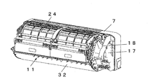
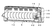
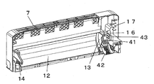
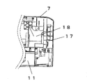
- FIG. 1 It is a perspective view which shows the indoor unit of the air conditioner which is embodiment of this invention. It is a longitudinal cross-sectional view which shows the inside of an indoor unit. It is a perspective view which shows the state which removed the front panel and left and right cover of an indoor unit. It is a perspective view which shows the state which removed the filter unit from the state of FIG. It is a perspective view which shows the state which removed the heat exchanger and the drain pan unit of the front part from the state of FIG. It is a perspective view of the backplate which shows the state which decomposed
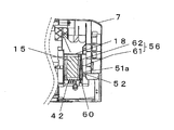
- FIG. 13 is a cross-sectional view taken along line AA in FIG. 12.
- FIG. 13 is a sectional view taken along line BB in FIG.
- FIG. 13 is a cross-sectional view taken along the line AA in a state in which the drain pan unit is removed in FIG. 12 and shows a state in which the locking piece is detached from the locking receiver.
- FIG. 1 the front panel 10 side is the front side
- the back plate 7 side is the back side or the back side
- the direction from the front panel 10 toward the back plate 7 is the front-rear direction
- the front panel 10 is the front side.
- the horizontal direction is the left-right direction.
- This type of air conditioner includes a heat exchanger housed in an indoor unit, a compressor, a four-way valve, an outdoor heat exchanger, and a throttle device (both not shown) housed in an outdoor unit (not shown).
- the refrigerant pipes are connected to form a refrigeration cycle, and various operation modes such as cooling, heating, and dehumidification can be executed.
- the indoor unit includes a ventilation path 4 extending from the suction port 2 to the outlet 3 in the housing 1, and a heat exchanger 5 disposed on the upstream side of the wind flow in the ventilation path 4. And a blower fan (cross flow fan) 6 disposed on the downstream side of the wind flow with respect to the heat exchanger 5 in the ventilation path 4.
- the housing 1 is formed in a box shape by combining a back plate 7, left and right covers 8, 9, a front panel 10 and a drain pan unit 11, and is made of a synthetic resin of an indoor unit. Constitutes the exterior.
- the back plate 7 is formed in a box shape with an open front so as to hold a part of the cross flow fan 6 and the heat exchanger 5 inside the housing, and the back has a flat portion that can be attached to the indoor wall.
- a rear guider 12 is provided on the front side of the back plate 7 to guide the air blown from the cross flow fan 6 to the blowout port 3. Further, the left and right side walls 13 and 14 of the back plate 7 rotatably support the rotating shaft portion 6a of the cross flow fan 6.
- the left and right covers 8 and 9 (the right cover 8 and the left cover 9) of the housing 1 are arranged on both the left and right sides of the back plate 7.
- the motor and electrical parts of the cross flow fan 6 can be accommodated in a space formed between the left and right side walls 13 and 14 of the back plate 7 and the left and right covers 8 and 9.
- the motor housing portion 16 of the fan motor 15 is formed outside the right side wall 13 in front view, and the electrical component housing portion 17 is further formed on the right side thereof.
- a side plate 18 that accommodates a U-bend pipe protruding from the side of the heat exchanger 5 and an inlet / outlet pipe is fixed to the back plate 7 with screws or the like above the motor accommodating portion 16.
- the suction port 2 is formed in the top surface portion of the housing 1 surrounded by the front panel 10 and the back plate 7, and dust is collected from the air sucked into the ventilation path 4 of the housing 1 on the back surface side.
- An air filter 21 for removing the air is disposed.
- a cleaning unit 24 including a brush 22 and a dust box 23 for cleaning the air filter 21 is provided from the housing 1 between the front panel 10 and the internal heat exchanger 5. Built-in detachable.
- the air filter 21 is incorporated in the guide path of the cleaning unit 24 and is movable along the suction port 2. The air filter 21 can be taken out from the front side by opening the front panel 10.
- the heat exchanger 5 is provided in the vicinity of the suction port 2 on the upstream side of the ventilation path 4 as shown in FIG.
- the heat exchanger 5 includes a front-side heat exchanger 5a and a back-side heat exchanger 5b arranged in an inverted V shape in a side view.
- an open U-shaped drain pan 25, which is a constituent member of the drain pan unit 11, is disposed under the heat exchanger 5a on the front side.
- a rear side drain pan 26 formed on the back side of the rear guider 12 of the back plate 7 is disposed below the back side heat exchanger 5b.
- the drain pan unit 11 includes a peripheral member 31 that forms the air outlet 3 at the center, a horizontal louver 32 that is pivotably provided in front of the air outlet 3 and closes the front opening in a closed posture, and a rear side of the horizontal louver 32. And a plurality of vertical louvers 34 arranged so as to be swingable behind the horizontal louver 32.
- the rectifying plate 33 is arranged at the outlet 3 to rectify the wind from the cross flow fan 6.
- the lower member 35 of the peripheral member 31 constitutes the lower exterior of the housing 1, and its rear end portion is locked to the front side portion of the back plate 7, and the peripheral member 31, that is, the drain pan unit 11 is screwed. Is fixed to the back plate 7 of the housing 1 and can be removed by loosening screws during maintenance of the cross flow fan 6.
- the upper surface of the lower member 35 is a blowing guide surface that is gently inclined downward and forward so as to be continuous with the rear guider 12 of the back plate 7.
- the cross flow fan 6 includes a plurality of blades having a predetermined length arranged in a cylindrical shape to form an impeller, and rotation shafts provided at the left and right ends of the cross flow fan 6 are the left and right side walls of the housing 1. The air sucked from the heat exchanger side is blown toward the blowout port 3 along the ventilation path wall from the lower side to the front side.
- a fan motor 15 having a motor shaft on the extension line of the rotary shaft 6a is arranged on the right side in a front view.
- the fan motor 15 has a well-known structure formed in a cylindrical shape, and is detachably fixed to the motor housing portion 16 of the back plate 7 by a motor fixing device 40.
- the motor fixing device 40 includes a motor receiving portion 41 formed in an arc concave shape covering the back plate 7 of the housing 1 and covering about 1/3 of the back side of the fan motor 15, and the motor receiving portion 41.
- a motor receiving portion 41 formed in an arc concave shape covering the back plate 7 of the housing 1 and covering about 1/3 of the back side of the fan motor 15, and the motor receiving portion 41.
- the side plate 18 is provided.
- the motor receiving portion 41 projects forward on the right side of the back plate 7 in a front view and partitions the right side wall 13 that receives the rotating shaft portion 6a of the crossflow fan 6, and the motor accommodating portion 16 and the electrical component accommodating portion 17.
- An arc concave shape is formed between the wall 43 and the wall 43.
- a concave portion 45 is formed on the front surface of the right side wall 13 to place a ring-shaped vibration-proof rubber member 44 disposed around the motor shaft of the fan motor 15.
- a recess 47 is formed in the front side of the partition wall 43 so as to place a disc-shaped vibration-proof rubber member 46 disposed at the axially outer end of the fan motor 15.
- the right side wall 13 and the partition wall 43 hold the fan motor 15 in the axial direction.
- the motor cover 42 is formed in a U-shaped cross section so as to cover both end surfaces of the fan motor 15 in the motor axial direction and a part of the outer peripheral surface of the fan motor 15.
- the fan motor 15 is sandwiched from the axial direction by cover side walls 42a and 42b on both axial end surfaces of the motor cover 42.
- the motor cover 42 and the motor receiving portion 41 are formed with a plurality of longitudinal slits for heat dissipation in order to release heat generated from the fan motor 15 to the outside.
- a plurality of longitudinal heat dissipating slits are formed on the surface of the motor cover 42 covering the outer peripheral surface of the fan motor.
- the motor cover 42 is supported at its one end side so as to be openable and closable by the bearing portion of the motor receiving portion 41 via a rotating shaft 48 parallel to the motor shaft of the fan motor 15.
- the other end portion of the motor cover 42 is detachably locked to the partition wall 43 of the motor receiving portion 42 via the locking portion 50.
- the rotation shaft 48 is formed so as to protrude inwardly at one end side of the left and right cover side walls 42a and 42b, and is fitted into a bearing hole (not shown) of the motor receiving portion 41. Thus, it can be opened and closed in the vertical direction.
- the open rotation posture of the motor cover 42 as shown in FIG. 7, the other end portion of the motor cover 42 is positioned below to open the motor receiving portion 41.
- the closed rotation posture of the motor cover 42 in the closed rotation posture of the motor cover 42, the other end portion of the motor cover 42 is rotated upward to the horizontal position to close the motor receiving portion 41.
- the protruding direction of the rotating shaft 48 may be set so as to protrude outward rather than inside the cover side wall.
- the side plate 18 accommodates the U-bend pipe and the entrance / exit pipe projecting from the side portion of the heat exchanger 5, and constitutes a part of the motor accommodation portion 16 on the back side thereof. It also functions as a motor cover that covers about 1/3 of the front upper side. Therefore, although not shown, recesses for supporting the anti-vibration rubber members 44 and 46 are formed on the left and right sides of the side plate 18, and the fan motor 15 is accommodated and supported in cooperation with the motor receiving portion 41 and the motor cover 42. Like to do.
- the locking portion 50 includes a locking piece 51 formed at the other end of the motor cover 42 so as to be elastically deformable in the axial direction of the motor shaft, and a housing side for deforming and locking the locking piece 51. And a latch receiver 52 formed on the partition wall 43 (see FIGS. 12 to 16).
- the locking piece 51 is curved and formed in an inverted U shape outside the right side wall 43 in the axial direction of the motor shaft, and can be elastically deformed in the axial direction of the motor shaft.
- a locking projection 51a having a right triangle is formed on the right outer surface of the locking piece 51 in a front view, and the locking projection 51a is rotated from below to a shelf-shaped locking receiver 52 formed horizontally from the partition wall 43. It is designed to lock while moving.
- the locking portion 50 has the locking protrusion 51 a on the right outer side of the locking piece 51 as the wall surface of the partition wall 43.
- the locking receiver 52 When the locking receiver 52 is reached, it is restored by rebound resilience and is elastically locked and supported by the locking receiver 52.
- the locking piece 51 may be detached from the locking receiver 52 due to vibration or impact during transportation. Therefore, in this example, two restricting portions 55 and 56 that restrict the movement of the motor cover 42 in the axial direction are provided.
- the first restricting portion 55 includes a restricting piece 57 protruding toward one end of the motor cover 42, and the restricting piece 57 by the closed rotation of the motor cover 42 around the rotating shaft 48. And a restriction hole 58 into which is inserted.
- the restriction hole 58 is provided in the back plate 7. The movement of the motor cover 42 in the rotational axis direction is restricted by the fitting position of the restriction piece 57 into the restriction hole 58, and the restriction piece 57 comes out of the restriction hole 58 in the rotation open position of the motor cover 42. Yes.
- the regulating piece 57 is configured such that one end side is extended from the rotating shaft 48 of the cover side walls 42a and 42b of the motor cover 42.
- the restriction hole 58 is formed in a slit shape on the motor receiving portion 41 provided on the back plate 7 so as to face the restriction piece 57.
- the restriction piece 57 contacts the slit hole wall of the restriction hole 58 to restrict the movement of the rotation shaft 48 in the axial direction.
- the restriction hole 58 is formed to have a wide upper side so that the restriction piece 57 can be easily received when the motor cover 42 changes from the rotation open position to the rotation close position.
- the second restricting portion 56 is configured so that the other end of the motor cover 42 is locked in the axial direction of the motor shaft after the other end of the motor cover 42 is locked by the locking portion 50. To prevent it from moving. That is, the other end portion of the motor cover 42 is locked to the locking receiver 52 of the motor receiving portion 41 due to the elastic deformation of the locking piece 51. Therefore, by restricting the elastic deformation, the motor cover 42 is moved to the motor receiving portion. Do not come off the part 41.
- a protrusion 60 that enters the inside of the U-shaped engaging piece 51 and restricts the elastic deformation of the engaging piece 51 is exemplified.
- the protrusion 60 is formed to protrude from a peripheral member that can be attached to and detached from the motor receiving portion 41.
- the protrusion 60 can be formed to protrude from the back side of the drain pan unit 11 that can be attached to and detached from the back plate 7 of the housing 1.
- the locking position of the locking piece 51 is maintained in contact with the peripheral member of the motor receiving portion 41 on the housing 1 side in the rotation closed posture of the motor cover 42.
- An extending portion 61 extending from the locking piece 51 is exemplified.
- the extending portion 61 is provided on the peripheral member.
- the extending portion 61 maintains the locking posture of the locking piece 51 and prevents the locking piece 51 from coming off the locking receiver 52.
- An example of the peripheral member in this case is the side plate 18 that guides the outlet pipe of the heat exchanger 5.
- a regulating plate 62 is extended from the side plate 18 to the back side so that the extending portion 61 of the locking piece 51 and the regulating plate 62 of the side plate 18 are in surface contact.
- the motor cover 42 is continuous with the motor receiving portion 41 on the housing 1 side and covers both end surfaces of the fan motor 15 in the axial direction of the motor and a part of the outer peripheral surface of the fan motor 15.
- the locking piece 51 of the portion 50 is locked to the partition wall 43 of the motor receiving portion 41. In this way, the movement of the fan motor 15 is restricted.
- the second restricting portion 56 restricts the other end portion of the motor cover 42 from moving after the other end portion of the motor cover 42 is locked by the locking portion 50. That is, the protrusion 60 protruding from the back side of the drain pan unit 11 enters the inside of the U-shaped locking piece 51 to restrict elastic deformation of the locking piece 51. Further, when the motor cover 42 is rotated and closed, the extending portion 61 of the locking piece 51 comes into contact with the restriction plate 62 of the side plate 18 to maintain the locking position. While strengthening, it does not get in the way when performing the correct disengagement and prevents the locking piece 51 from coming off the locking receiver.
- the front panel 10, the cleaning unit, the drain pan unit 11, and the side plate 18 are sequentially removed from the state shown in FIG.
- the side plate 18 and the drain pan unit 11 the restraint of the latching piece 51 of the latching portion is released and elastic deformation is possible. Therefore, the latching piece 51 is bent and detached from the latching receiver, and the motor cover 42 is released. Is pivoted around the pivot shaft 48. Thereby, the motor cover 42 is opened and the motor can be taken out. Therefore, the maintenance work can be easily performed as compared with the case where the motor cover 42 is fixed using screws or screws.
- the first restricting portion 55 causes the rotation shaft 48 on the one end side of the motor cover 42 to move.
- the movement in the axial direction is regulated, and the elastically deformable locking piece 51 works to maintain the locking posture by the protrusion 60 and the regulating plate 62, so that the motor can be used without using screws or screws.
- the cover 42 can be prevented from being removed, and vibration from the fan motor can be effectively prevented.
- cross flow fan cross flow fan
- blower fan blower fan
- the protrusion 60 as the second restricting portion protrudes from the drain pan unit 11
- a structure protruding from the back surface of the front panel 10 or the right cover 8 may be adopted.
- the restricting plate 62 that contacts the extending portion 61 that is the second restricting portion is not limited to a configuration that protrudes from the side plate 18, and is attached to another member that constitutes the housing, for example, the right cover 8. It may be the configuration.
- the second restricting portion is not only configured by the restricting portions of the protrusion 60 and the extending portion 61 and the restricting plate 62, but any one restricting portion (for example, You may comprise only the protrusion 60 or only the extending part 61 and the control board 62).
Landscapes
- Engineering & Computer Science (AREA)
- Chemical & Material Sciences (AREA)
- Combustion & Propulsion (AREA)
- Mechanical Engineering (AREA)
- General Engineering & Computer Science (AREA)
- Devices For Blowing Cold Air, Devices For Blowing Warm Air, And Means For Preventing Water Condensation In Air Conditioning Units (AREA)
Abstract
本発明は、ネジ等を使用しないでメンテナンス時の作業性を向上させると共に、輸送中の振動・衝撃にもモータカバー42が外れるのを防止できるモータ固定装置40を備えた空気調和機を提供する。モータカバーの一端側をファンモータ15のモータ軸と平行な回動軸48周りに開閉回動可能にモータ支持部に支持し、モータカバーの他端部をモータ受け部41に係止し、さらに、モータカバーの一端側における回動軸の軸方向への移動を規制する第1の規制部55として、モータカバーの一端側に突出する規制片57と、前記モータカバー42の前記回動軸周りの閉回動で前記規制片57が嵌入する規制穴58とを備え、規制片の規制穴への嵌入姿勢でモータカバーの回動軸方向への移動を規制する。
Description
本発明は、送風ファンおよびそのファンモータを備えた空気調和機に関するものである。
従来の空気調和機においては、送風ファンの故障により送風ファンの交換が必要になったり、あるいは送風ファンの清掃等のメンテナンスを行なう際に、送風ファンを筐体内から取り外すために、送風ファンやファンモータは筐体内に着脱可能に装着されている(特許文献1~4参照)。
例えば、特許文献4の空気調和機では、横流ファン(クロスフローファン)の一端を枢支する軸受けと、モータ受け部に固定ねじを介して取り付けられファンモータを挟持するモータカバーとを備え、モータカバーの固定ねじを取外すことにより、ファンモータをモータ受け部から取り外すことができるようになっている。
ところで、送風ファンのファンモータは、筐体側のモータ受け部とモータカバーとで囲まれたモータ収容部に収容されるが、その際、ファンモータの駆動時に発生する振動が筐体側に伝達するのを防止するため、防振ゴム等の防振材を介してモータ収容部に着脱可能に取り付けられる。
したがって、モータ収容部を構成するモータ受け部とモータカバーとはネジやビスにより強固に固定され、ファンモータからの振動が筐体側に伝達されるのを防止しているが、ファンモータのメンテナンス時にネジやビスの締付けを解除する必要があり、作業性が悪くなるといった課題がある。
一方、モータカバーを係合爪等によりモータ受け部に係止し、メンテナンス時の作業性を良好にすることも考えられるが、係止部によるモータカバーの固定は、輸送中の振動や衝撃により、係止爪が離脱してモータカバーの係止が外れるおそれがある。
モータカバーが外れる、あるいは緩むと、空気調和機の使用時に、ファンモータで発生した振動が筐体側に伝わりやすくなり、不快音を発生するおそれがある。
本発明は、上記に鑑み、メンテナンス時の作業性を向上させると共に、輸送中の振動・衝撃にもモータカバーが外れるのを防止できる空気調和機の提供を目的としている。
上記目的を達成するために、本発明は、筐体内に着脱可能に配置された送風ファンおよびそのファンモータと、筐体側のモータ受け部に対向して配置され、前記ファンモータのモータ軸方向両端面の一部およびファンモータの外周面の一部を覆うモータカバーとを備え、前記モータカバーは、その一端側がファンモータのモータ軸と平行な回動軸を介して前記モータ受け部に開閉回動可能に支持され、他端部が係止部を介して前記モータ受け部に係脱可能に係止され、前記モータカバーの一端側における前記回動軸の軸方向への移動を規制する第1の規制部が設けられたことを特徴とする。
上記構成によると、モータカバーが、筐体側のモータ受け部に対向して、前記ファンモータのモータ軸方向両端面およびファンモータの外周面の一部を覆っており、係止部がモータ受け部に係止しているため、ファンモータの移動が規制されるが、空気調和機の輸送中における振動・衝撃により、係止部が外れた場合でも、モータカバーの一端側における回動軸の軸方向への移動は、第1の規制部により規制されるので、ネジやビス等を使用しなくても、回動軸が軸方向に移動するのを防止することができる。
第1の規制部の具体例としては、前記モータカバーの一端側に突出する規制片と、前記モータカバーの前記回動軸周りの閉回動で前記規制片が嵌入する規制穴とを備えた構成が挙げられ、規制片の規制穴への嵌入姿勢で前記モータカバーの回動軸方向への移動が規制される。
上記構成によると、モータカバーの一端側に突出する規制片をモータ受け部側の規制穴に嵌入するだけの簡単な構成により、モータカバーの回動軸方向への移動が規制される。また、モータカバーの回動開姿勢では規制片が規制穴から抜け出すようになっている。
また、係止部は、モータカバーの他端部に弾性変形可能な係止片と、該係止片を変形させて係合固定する筐体側の係止受けとを備えた構成が例示される。係止片の形状は特に限定されないが、例えば、U字形に湾曲形成されたものが挙げられる。このような係止部には、前記係止片の弾性変形を規制して前記係止受けからの離脱を防止する第2の規制部を設けることができる。
第2の規制部は、モータカバーの他端部が係止部により係止された後、モータカバーの他端部が動かないよう規制する。つまり、係止部の弾性変形によりモータカバーの他端部がモータ受け部に係止されているので、その弾性変形を規制することにより、モータカバーがモータ受け部から外れないようにする。
第2の規制部を例示すると、前記係止片の内側に侵入して前記係止片の弾性変形を規制する突起から構成する。この突起は、モータ受け部の着脱可能な周辺部材に突出形成するのが好ましい。例えば、筐体に対して着脱可能なドレンパンユニットの背面側から突出形成することができる。
第2の規制部の他の例を説明すると、前記モータカバーの回動閉姿勢で、筐体側のモータ受け部の周辺部材に当接して前記係止片の係止姿勢を維持させるよう、前記係止片から延設された延設部が挙げられる。これにより、係止片の係止姿勢が維持され、係止片が係止受けから外れるのを防止することができる。
以上のとおり、本発明によると、輸送中の振動・衝撃により、モータカバーの係止部が外れたとしても、モータカバーの一端側における回動軸の軸方向への移動が、第1の規制部により規制されるので、モータカバーが外れるのを防止することができ、ファンモータからの振動を効果的に防止することができる。
以下、本発明の実施形態を図面に基づいて説明する。本実施形態では、セパレート型空気調和機の室内ユニットを例に説明する。なお、図1において、前面パネル10側を前側、背面板7側を背面若しくは後側とし、以下の説明では、前面パネル10から背面板7に向かう方向を前後方向とし、また前面パネル10を正面からみて、その横方向を左右方向とする。この種の空気調和機は、室内ユニットの内部に収容される熱交換器と、図示しない室外ユニットに収容される圧縮機、四方弁、室外熱交換器、絞り装置(共に図示せず)とが冷媒管によって接続されて冷凍サイクルが構成され、冷房、暖房、除湿などの各種運転モードを実行できるようになっている。
室内ユニットは、図2に示すように、筐体1内に、吸込口2から吹出口3に至る通風路4と、該通風路4の風の流れの上流側に配置された熱交換器5と、前記通風路4において熱交換器5よりも風の流れの下流側に配置された送風ファン(クロスフローファン)6とを備えている。
筐体1は、図1に示すように、背面板7と、左右のカバー8,9と、前面パネル10とドレンパンユニット11とが互いに組み合わされて箱形に形成され、室内ユニットの合成樹脂製の外装を構成している。
背面板7は、筐体内部のクロスフローファン6および熱交換器5の一部を保持するよう前面開放の箱形に形成され、その背面は室内壁に取付可能な平面部を備えている。また、背面板7の前面側には、クロスフローファン6からの送風を吹出口3に案内するリアガイダ12を備えている。さらに、背面板7の左右の側壁13,14はクロスフローファン6の回転軸部6aを回転可能に軸受けしている。
筐体1の左右のカバー8,9(右カバー8、左カバー9)は、背面板7の左右両側に配置される。背面板7の左右の側壁13,14と左右のカバー8,9との間に形成された空間部にクロスフローファン6のモータや電装部品を収容できるようになっている。本例では、正面視で右側の側壁13の外側にファンモータ15のモータ収容部16が形成され、さらにその右側に電装部品収容部17が形成されている。
モータ収容部16の上方には熱交換器5の側部から突出するUベンド管と出入り口パイプとを収容する側板18が背面板7にビス等により固定されている。
吸込口2は、図1に示すように、前面パネル10と背面板7とで囲まれた筐体1の天面部に形成され、その裏面側に筐体1の通風路4に吸い込む空気から塵埃を除去するエアフィルタ21が配置されている。
また、図2に示すように、前面パネル10と内部の熱交換器5との間で、筐体内にはエアフィルタ21を清掃するブラシ22及びダストボックス23を備えた清掃ユニット24が筐体1から着脱可能に内蔵されている。前記清掃ユニット24の案内路には前記エアフィルタ21が組み込まれて吸込口2に沿って移動可能とされている。また、エアフィルタ21は、前面パネル10を開放することにより、前側から取り出すことができる。
熱交換器5は、図2に示すように、通風路4の送風上流側で吸込口2の近傍に設けられる。この熱交換器5は、前面側の熱交換器5aと背面側の熱交換器5bとが側面視で逆V字形に配置されてなる。
前面側の熱交換器5aの下方には前記ドレンパンユニット11の一構成部材である断面上開放コ字形のドレンパン25が配置される。背面側の熱交換器5bの下方には背面板7のリアガイダ12の背面側に形成されたリア側ドレンパン26が配置される。
ドレンパンユニット11は、中央部に吹出口3を形成する周縁部材31と、吹出口3の前方に回動可能に設けられ、閉姿勢で前面開口を塞ぐ横ルーバ32と、横ルーバ32の後側で吹出口3に配置されクロスフローファン6からの風を整流する整流板33と、横ルーバ32の後方に揺動可能に配置された複数の縦ルーバ34とを備えている。
周縁部材31の下側部材35は、筐体1の下側外装を構成するもので、その後端部が背面板7の前側部に係止されると共に、周縁部材31、つまりドレンパンユニット11がネジにより筐体1の背面板7に固定され、クロスフローファン6のメンテナンス時にネジを緩めて取外しできるようになっている。下側部材35の上面は、背面板7のリアガイダ12に連続するよう緩やかに前方へ下り傾斜した送風案内面とされる。
クロスフローファン6は、図6に示すように、所定長さの複数のブレードが円筒状に配列されて羽根車が構成され、その左右両端に設けられた回転軸が筐体1の左右の側壁13,14に回転可能に軸受けされ、熱交換器側から吸い込んだ空気を下方から前方に向かう通風路壁に沿って吹出口3側に向かって送風するようになっている。
クロスフローファン6には、正面視で右側に回転軸6aの延長線上でモータ軸を備えたファンモータ15が配置される。このファンモータ15は、図6に示すように、円筒状に形成された周知構造のもので、モータ固定装置40により背面板7のモータ収容部16に着脱可能に固定されている。
モータ固定装置40は、図6に示すように、筐体1の背面板7にファンモータ15の背面側1/3程度を覆う円弧凹状に形成されたモータ受け部41と、該モータ受け部41に連続するように配置されてファンモータ15の前面下側1/3程度を覆う円弧凹状のモータカバー42と、モータカバー42に連続するように配置されファンモータ15の前面上側1/3を覆う前記側板18とを備えている。
モータ受け部41は、正面視で背面板7の右側で前方に突出しクロスフローファン6の回転軸部6aを軸受けする右側壁13と、モータ収容部16と電装部品収容部17とを区画する区画壁43との間に円弧凹状に形成されている。さらに、右側壁13の前面には、ファンモータ15のモータ軸の周囲に配置されたリング状の防振ゴム部材44を載置する凹部45が形成されている。また、区画壁43の前面側には、ファンモータ15の軸方向外端部に配置された円盤状の防振ゴム部材46を載置する凹部47が切欠き形成されている。そして、右側壁13と区画壁43とでファンモータ15を軸方向で挟持するようになっている。
モータカバー42は、図6および図9に示すように、ファンモータ15のモータ軸方向両端面およびファンモータ15の外周面の一部を覆うよう断面コ字形に形成されている。モータカバー42の軸方向両端面のカバー側壁42a、42bによりファンモータ15を軸方向から挟持するようになっている。このモータカバー42および前記モータ受け部41には、ファンモータ15からの発熱を外部に逃がすため、複数状の縦方向の放熱用スリットが形成されている。図9では、モータカバー42のファンモータの外周面を覆う面に、複数状の縦方向の放熱用スリットが形成されている。なお、カバー側壁42a、42bに放熱用のスリットを形成してもよい。
また、モータカバー42は、その一端側がファンモータ15のモータ軸と平行な回動軸48を介して前記モータ受け部41の軸受け部に開閉回動可能に支持されている。そして、モータカバー42の他端部が係止部50を介して前記モータ受け部42の区画壁43に係脱可能に係止されている。
回動軸48は、図6および図9に示すように、左右のカバー側壁42a、42bの一端側に内側に突出するように形成され、モータ受け部41の軸受け穴(図示略)に嵌合して、上下方向に開閉回動可能とされる。モータカバー42の開回動姿勢では、図7に示すように、モータカバー42の他端部が下方に位置しモータ受け部41を開放するようになっている。また、図8に示すように、モータカバー42の閉回動姿勢では、モータカバー42の他端部が水平位置まで上回動してモータ受け部41を閉じるようにしている。なお、回動軸48の突出方向は、カバー側壁の内側ではなく、外側に突出するように設定してもよい。
前記側板18は、前述のとおり、熱交換器5の側部から突出するUベンド管および出入り口パイプとを収容するが、その背面側においてモータ収容部16の一部を構成し、ファンモータ15の前面上側1/3程度を覆うモータカバーとしても機能する。したがって、図示しないが、側板18の左右両側には、防振ゴム部材44,46を支持する凹部が形成され、前記モータ受け部41およびモータカバー42と協働して、ファンモータ15を収容支持するようにしている。
係止部50は、モータカバー42の他端部にモータ軸の軸方向に弾性変形可能に形成された係止片51と、該係止片51を変形させて係合固定するために筐体側の区画壁43に形成された係止受け52とを備えている(図12から図16を参照)。
係止片51は、モータ軸の軸方向で右側のカバー側壁43の外側に逆U字形に湾曲形成され、モータ軸の軸方向に弾性変形可能とされている。係止片51の右外側面には正面視で直角三角形の係止突起51aが形成され、この係止突起51aが区画壁43から水平に形成された棚状の係止受け52に下方から回動しながら係止するようになっている。
したがって、係止部50は、モータカバー42の閉回動により、モータカバー42の他端部が上回動したとき、係止片51の右外側にある係止突起51aが区画壁43の壁面に沿って上動し、係止受け52に到達したときに反発弾性により復帰して係止受け52に弾性的に係止支持される。
しかし、係止部50のみでは輸送中の振動・衝撃等により係止片51が係止受け52から離脱するおそれがある。そこで、本例では、前記モータカバー42の軸方向への移動を規制する2つの規制部55、56が設けられている。
第1の規制部55は、図9に示すように、前記モータカバー42の一端側に突出する規制片57と、前記モータカバー42の前記回動軸48周りの閉回動で前記規制片57が嵌入する規制穴58とを備える。規制穴58は背面板7に設けられている。規制片57の規制穴58への嵌入姿勢で前記モータカバー42の回動軸方向への移動が規制され、モータカバー42の回動開姿勢では規制片57が規制穴58から抜け出すようになっている。
規制片57は、モータカバー42のカバー側壁42a、42bの回動軸48よりも一端側が延長されて構成される。規制穴58は、図9に示すように、背面板7に設けられているモータ受け部41に規制片57に対向してスリット状に形成されている。モータカバー42の回動閉姿勢において、規制片57が規制穴58のスリット穴壁に当接して回動軸48の軸方向への移動を規制する。規制穴58は、図9に示すように、上側が幅広に形成され、モータカバー42が回動開姿勢から回動閉姿勢となる際に、規制片57を受け入れやすくしている。
第2の規制部56は、図9~図16に示すように、モータカバー42の他端部が係止部50により係止された後、モータカバー42の他端部がモータ軸の軸方向に動かないよう規制する。つまり、係止片51の弾性変形によりモータカバー42の他端部がモータ受け部41の係止受け52に係止されているので、その弾性変形を規制することにより、モータカバー42がモータ受け部41から外れないようにする。
第2の規制部56として、図9に示すように、前記U字形の係止片51の内側に侵入して前記係止片51の弾性変形を規制する突起60が例示される。この突起60は、モータ受け部41に着脱可能な周辺部材に突出形成する。例えば、筐体1の背面板7に対して着脱可能なドレンパンユニット11の背面側から突起60を突出形成することができる。
さらに、第2の規制部56として、モータカバー42の回動閉姿勢で、筐体1側のモータ受け部41の周辺部材に当接して前記係止片51の係止姿勢を維持させるよう、前記係止片51から延設された延設部61が挙げられる。この延設部61は、周辺部材に設けられている。延設部61は係止片51の係止姿勢を維持し、係止片51が係止受け52から外れるのを防止している。この場合の周辺部材としては、熱交換器5の出切り口パイプを案内する側板18が例示できる。側板18から背面側に規制板62を延設し、係止片51の延設部61と側板18の規制板62とが面接触するようにしている。
上記構成においては、モータカバー42が、筐体1側のモータ受け部41に連続して、ファンモータ15のモータ軸方向両端面およびファンモータ15の外周面の一部を覆っており、係止部50の係止片51がモータ受け部41の区画壁43に係止している。このように、ファンモータ15の移動が規制される。
しかし、空気調和機の輸送中における振動・衝撃により、係止部50が外れた場合、モータカバー42の一端側における回動軸の軸方向への移動は、第1の規制部55の規制片57がスリット状の規制穴58に侵入して、規制穴58の穴壁に食い込むようになる。そのため、ネジやビス等を使用しなくても、回動軸が軸方向に移動するのを防止することができる。
また、第2の規制部56は、モータカバー42の他端部が係止部50により係止された後、モータカバー42の他端部が動かないよう規制する。つまり、ドレンパンユニット11の背面側から突出する突起60をU字形の係止片51の内側に侵入させて係止片51の弾性変形を規制する。また、モータカバー42の回動閉姿勢で、側板18の規制板62に係止片51の延設部61が当接して、その係止姿勢を維持させるので、係止片の係止姿勢を強める一方、正しい外し方を行なう際には邪魔にならず、係止片51が係止受けから外れるのを防止する。
一方、クロスフローファン6を取り外してメンテナンスを行なうには、図1の状態から、前面パネル10、清掃ユニット、ドレンパンユニット11、側板18を順次取り外す。側板18およびドレンパンユニット11を取外すことで、係止部の係止片51の拘束が解除されて弾性変形可能となるので、係止片51を撓ませて係止受けから離脱させ、モータカバー42を回動軸48の回りに開回動する。これにより、モータカバー42が開放されてモータを取り出すことができる。したがって、ネジやビスを使ってモータカバー42を固定する場合に比べて、メンテナンス作業が容易に行える。
また、空気調和機の使用時には、輸送中の振動・衝撃により、モータカバー42の係止部50が外れたとしても、第1の規制部55によりモータカバー42の一端側における回動軸48の軸方向への移動を規制し、また、弾性変形可能な係止片51が突起60や規制板62により係止姿勢を維持するように働くので、ネジやビス等を使用しなくても、モータカバー42が外れるのを防止することができ、ファンモータからの振動を効果的に防止することができる。
なお、本発明は、上記実施形態に限定されるものではなく、本発明の範囲内で多くの修正・変更を加えることができるのは勿論である。例えば、本例では送風ファンとしてクロスフローファン(横流ファン)を例示したが、これに限らず、他の形式のファンであってもよい。
また、第2の規制部としての突起60は、ドレンパンユニット11から突出形成した例を示したが、前面パネル10や右カバー8の裏面から突出する構成を採用してもよい。さらに、第2の規制部である延設部61に当接する規制板62も側板18から突出させる構成に限定されるものではなく、筐体を構成する他の部材、例えば、右カバー8に付設した構成であってもよい。さらに、第2の規制部は、本例にように、突起60と、延設部61および規制板62との両規制部により構成するのみならず、そのうちのいずれか一方の規制部(例えば、突起60のみ、あるいは延設部61および規制板62のみ)によって構成してもよい。
1 筐体
2 吸込口
3 吹出口
4 通風路
5 熱交換器
5a 前面側熱交換器
5b 背面側熱交換器
6 送風ファン
6a 回転軸(モータ軸)
7 背面板
8 右カバー
9 左カバー
10 前面パネル
11 ドレンパンユニット
12 リアガイダ
13 右側壁
14 左側壁
15 ファンモータ
16 モータ収容部
17 電装部品収容部
18 パイプ案内用側板
21 エアフィルタ
22 ブラシ
23 ダストボックス
24 清掃ユニット
25 ドレンパン
26 リア側ドレンパン
31 周縁部材
32 横ルーバ
33 整流板
34 縦ルーバ
35 下側部材
40 モータ固定装置
41 モータ受け部
42 モータカバー
42a、42b カバー側壁
43 区画壁
44 リング状の防振ゴム部材
45 右側壁側の凹部
46 円盤状の防振ゴム部材
47 区画壁側の凹部
48 回動軸
50 係止部
51 係止片
51a 係止突起
52 係止受け
55 第1の規制部
56 第2の規制部
57 規制片
58 規制穴
61 延設部
62 規制板
2 吸込口
3 吹出口
4 通風路
5 熱交換器
5a 前面側熱交換器
5b 背面側熱交換器
6 送風ファン
6a 回転軸(モータ軸)
7 背面板
8 右カバー
9 左カバー
10 前面パネル
11 ドレンパンユニット
12 リアガイダ
13 右側壁
14 左側壁
15 ファンモータ
16 モータ収容部
17 電装部品収容部
18 パイプ案内用側板
21 エアフィルタ
22 ブラシ
23 ダストボックス
24 清掃ユニット
25 ドレンパン
26 リア側ドレンパン
31 周縁部材
32 横ルーバ
33 整流板
34 縦ルーバ
35 下側部材
40 モータ固定装置
41 モータ受け部
42 モータカバー
42a、42b カバー側壁
43 区画壁
44 リング状の防振ゴム部材
45 右側壁側の凹部
46 円盤状の防振ゴム部材
47 区画壁側の凹部
48 回動軸
50 係止部
51 係止片
51a 係止突起
52 係止受け
55 第1の規制部
56 第2の規制部
57 規制片
58 規制穴
61 延設部
62 規制板
Claims (7)
- 筐体内に着脱可能に配置された送風ファンおよびそのファンモータと、筐体側のモータ受け部に対向して配置され、前記ファンモータのモータ軸方向両端面の一部およびファンモータの外周面の一部を覆うモータカバーとを備え、
前記モータカバーは、その一端側がファンモータのモータ軸と平行な回動軸を介して前記モータ受け部に開閉回動可能に支持され、他端部が係止部を介して前記モータ受け部に係脱可能に係止され、前記モータカバーの一端側における前記回動軸の軸方向への移動を規制する第1の規制部が設けられたことを特徴とする空気調和機。 - 前記第1の規制部は、前記モータカバーの一端側に突出する規制片と、前記モータカバーの前記回動軸周りの閉回動で前記規制片が嵌入する規制穴とを備え、前記規制片の規制穴への嵌入姿勢で前記モータカバーの回動軸方向への移動が規制されることを特徴とする請求項1に記載の空気調和機。
- 前記係止部は、モータカバーの他端部に弾性変形可能な係止片と、該係止片を変形させて係合固定する筐体側の係止受けとを備え、前記係止片の弾性変形を規制して前記係止受けからの離脱を防止する第2の規制部が設けられたことを特徴とする請求項1または2に記載の空気調和機。
- 前記弾性変形可能な係止片は、U字形に湾曲形成されていることを特徴とする請求項3に記載の空気調和機。
- 第2の規制部は、前記係止片の内側に侵入して前記係止片の弾性変形を規制する突起から構成されたことを特徴とする請求項3または4に記載の空気調和機。
- 第2の規制部は、前記モータカバーの回動閉姿勢で、筐体側のモータ受け部の周辺部材に当接して前記係止片の係止姿勢を維持させるよう、前記係止片に延設された延設部を備えたことを特徴とする請求項3または4に記載の空気調和機。
- 第2の規制部は、前記係止片の内側に侵入して前記係止片の弾性変形を規制する突起と、前記モータカバーの回動閉姿勢で、筐体側のモータ受け部周辺部材に当接して前記係止片の係止姿勢を維持させるよう前記係止片に延設された延設部とを備えたことを特徴とする請求項3または4に記載の空気調和機。
Priority Applications (1)
| Application Number | Priority Date | Filing Date | Title |
|---|---|---|---|
| CN201290000270.7U CN203454262U (zh) | 2011-02-17 | 2012-02-17 | 空气调节机 |
Applications Claiming Priority (2)
| Application Number | Priority Date | Filing Date | Title |
|---|---|---|---|
| JP2011031708A JP5134101B2 (ja) | 2011-02-17 | 2011-02-17 | 空気調和機 |
| JP2011-031708 | 2011-02-17 |
Publications (1)
| Publication Number | Publication Date |
|---|---|
| WO2012111797A1 true WO2012111797A1 (ja) | 2012-08-23 |
Family
ID=46672708
Family Applications (1)
| Application Number | Title | Priority Date | Filing Date |
|---|---|---|---|
| PCT/JP2012/053799 Ceased WO2012111797A1 (ja) | 2011-02-17 | 2012-02-17 | 空気調和機 |
Country Status (3)
| Country | Link |
|---|---|
| JP (1) | JP5134101B2 (ja) |
| CN (1) | CN203454262U (ja) |
| WO (1) | WO2012111797A1 (ja) |
Families Citing this family (3)
| Publication number | Priority date | Publication date | Assignee | Title |
|---|---|---|---|---|
| CN106196545A (zh) * | 2016-07-15 | 2016-12-07 | 广东志高空调有限公司 | 一种导风条组件以及空调 |
| JP2018136087A (ja) * | 2017-02-22 | 2018-08-30 | シャープ株式会社 | モータ押さえ機構、空気調和機 |
| JP2024034096A (ja) * | 2022-08-31 | 2024-03-13 | パナソニックIpマネジメント株式会社 | 空気調和機の室内機 |
Citations (7)
| Publication number | Priority date | Publication date | Assignee | Title |
|---|---|---|---|---|
| JPS579024U (ja) * | 1980-06-02 | 1982-01-18 | ||
| JPH0579319U (ja) * | 1992-03-25 | 1993-10-29 | 日本無機株式会社 | 空調用フィルタ |
| JPH08278039A (ja) * | 1995-04-04 | 1996-10-22 | Techno Oote:Kk | 枠体取付金具 |
| JPH11325499A (ja) * | 1998-05-20 | 1999-11-26 | Fujitsu General Ltd | 空気調和機のファンケーシング |
| JP2000028156A (ja) * | 1998-07-08 | 2000-01-25 | Hitachi Ltd | 空気調和機室内ユニットの部品構造及び部品の組立方法 |
| JP2001153392A (ja) * | 2000-10-23 | 2001-06-08 | Toshiba Kyaria Kk | 空気調和機の室内ユニット |
| JP2002071157A (ja) * | 2000-08-30 | 2002-03-08 | Toshiba Kyaria Kk | 空気調和機 |
Family Cites Families (3)
| Publication number | Priority date | Publication date | Assignee | Title |
|---|---|---|---|---|
| JPH08145395A (ja) * | 1994-11-18 | 1996-06-07 | Sanyo Electric Co Ltd | 熱交換ユニット |
| JPH08338644A (ja) * | 1995-06-14 | 1996-12-24 | Toshiba Ave Corp | 空気調和機 |
| JP4049054B2 (ja) * | 2003-08-27 | 2008-02-20 | ダイキン工業株式会社 | 遠心送風機のスクロールケーシング、それを備えた遠心送風機、及び空気調和装置の室内ユニット |
-
2011
- 2011-02-17 JP JP2011031708A patent/JP5134101B2/ja not_active Expired - Fee Related
-
2012
- 2012-02-17 WO PCT/JP2012/053799 patent/WO2012111797A1/ja not_active Ceased
- 2012-02-17 CN CN201290000270.7U patent/CN203454262U/zh not_active Expired - Lifetime
Patent Citations (7)
| Publication number | Priority date | Publication date | Assignee | Title |
|---|---|---|---|---|
| JPS579024U (ja) * | 1980-06-02 | 1982-01-18 | ||
| JPH0579319U (ja) * | 1992-03-25 | 1993-10-29 | 日本無機株式会社 | 空調用フィルタ |
| JPH08278039A (ja) * | 1995-04-04 | 1996-10-22 | Techno Oote:Kk | 枠体取付金具 |
| JPH11325499A (ja) * | 1998-05-20 | 1999-11-26 | Fujitsu General Ltd | 空気調和機のファンケーシング |
| JP2000028156A (ja) * | 1998-07-08 | 2000-01-25 | Hitachi Ltd | 空気調和機室内ユニットの部品構造及び部品の組立方法 |
| JP2002071157A (ja) * | 2000-08-30 | 2002-03-08 | Toshiba Kyaria Kk | 空気調和機 |
| JP2001153392A (ja) * | 2000-10-23 | 2001-06-08 | Toshiba Kyaria Kk | 空気調和機の室内ユニット |
Also Published As
| Publication number | Publication date |
|---|---|
| CN203454262U (zh) | 2014-02-26 |
| JP5134101B2 (ja) | 2013-01-30 |
| JP2012172852A (ja) | 2012-09-10 |
Similar Documents
| Publication | Publication Date | Title |
|---|---|---|
| US20180073755A9 (en) | Indoor device for air conditioner having wind visors | |
| JP5134101B2 (ja) | 空気調和機 | |
| JP2015218996A (ja) | 空気調和機の風向調整装置および空気調和機 | |
| WO2006022129A1 (ja) | 床置き型空気調和機 | |
| JP6524217B2 (ja) | 天井埋込形空気調和装置 | |
| JP6611827B2 (ja) | 空気調和装置 | |
| JP5195130B2 (ja) | 換気装置 | |
| JP5169592B2 (ja) | 換気装置 | |
| JP2012112546A (ja) | 空気調和機 | |
| JP6160156B2 (ja) | 空調室内機 | |
| JP5396909B2 (ja) | 天井埋込形換気扇 | |
| JP5590863B2 (ja) | 空気調和機 | |
| JPH10141698A (ja) | 床置型空気調和機 | |
| CN203478453U (zh) | 室外机 | |
| CN100565022C (zh) | 空调的室内单元 | |
| KR101666222B1 (ko) | 공기 조화기의 실내기 | |
| JP5067180B2 (ja) | 換気装置 | |
| CN112240607B (zh) | 送风装置、空气调节机的室内机 | |
| JP5527342B2 (ja) | 換気装置 | |
| KR102107342B1 (ko) | 크로스 플로우 팬 | |
| KR20250150416A (ko) | 공기조화기의 실내기 | |
| JP5606386B2 (ja) | 換気扇 | |
| JP5099108B2 (ja) | 設備機器 | |
| KR20070053548A (ko) | 공기조화기 실내기의 컨트롤박스 | |
| JP5369829B2 (ja) | 換気装置 |
Legal Events
| Date | Code | Title | Description |
|---|---|---|---|
| WWE | Wipo information: entry into national phase |
Ref document number: 201290000270.7 Country of ref document: CN |
|
| 121 | Ep: the epo has been informed by wipo that ep was designated in this application |
Ref document number: 12746605 Country of ref document: EP Kind code of ref document: A1 |
|
| NENP | Non-entry into the national phase |
Ref country code: DE |
|
| 122 | Ep: pct application non-entry in european phase |
Ref document number: 12746605 Country of ref document: EP Kind code of ref document: A1 |