WO2012111571A1 - ジョイントコネクタ及び端子半挿入検査方法 - Google Patents
ジョイントコネクタ及び端子半挿入検査方法 Download PDFInfo
- Publication number
- WO2012111571A1 WO2012111571A1 PCT/JP2012/053170 JP2012053170W WO2012111571A1 WO 2012111571 A1 WO2012111571 A1 WO 2012111571A1 JP 2012053170 W JP2012053170 W JP 2012053170W WO 2012111571 A1 WO2012111571 A1 WO 2012111571A1
- Authority
- WO
- WIPO (PCT)
- Prior art keywords
- terminal
- joint
- fitting
- housing
- female terminal
- Prior art date
- Legal status (The legal status is an assumption and is not a legal conclusion. Google has not performed a legal analysis and makes no representation as to the accuracy of the status listed.)
- Ceased
Links
Images





Classifications
-
- H—ELECTRICITY
- H01—ELECTRIC ELEMENTS
- H01R—ELECTRICALLY-CONDUCTIVE CONNECTIONS; STRUCTURAL ASSOCIATIONS OF A PLURALITY OF MUTUALLY-INSULATED ELECTRICAL CONNECTING ELEMENTS; COUPLING DEVICES; CURRENT COLLECTORS
- H01R13/00—Details of coupling devices of the kinds covered by groups H01R12/70 or H01R24/00 - H01R33/00
- H01R13/40—Securing contact members in or to a base or case; Insulating of contact members
- H01R13/42—Securing in a demountable manner
- H01R13/422—Securing in resilient one-piece base or case, e.g. by friction; One-piece base or case formed with resilient locking means
- H01R13/4223—Securing in resilient one-piece base or case, e.g. by friction; One-piece base or case formed with resilient locking means comprising integral flexible contact retaining fingers
-
- G—PHYSICS
- G01—MEASURING; TESTING
- G01R—MEASURING ELECTRIC VARIABLES; MEASURING MAGNETIC VARIABLES
- G01R27/00—Arrangements for measuring resistance, reactance, impedance, or electric characteristics derived therefrom
- G01R27/02—Measuring real or complex resistance, reactance, impedance, or other two-pole characteristics derived therefrom, e.g. time constant
-
- H—ELECTRICITY
- H01—ELECTRIC ELEMENTS
- H01R—ELECTRICALLY-CONDUCTIVE CONNECTIONS; STRUCTURAL ASSOCIATIONS OF A PLURALITY OF MUTUALLY-INSULATED ELECTRICAL CONNECTING ELEMENTS; COUPLING DEVICES; CURRENT COLLECTORS
- H01R13/00—Details of coupling devices of the kinds covered by groups H01R12/70 or H01R24/00 - H01R33/00
- H01R13/64—Means for preventing incorrect coupling
- H01R13/641—Means for preventing incorrect coupling by indicating incorrect coupling; by indicating correct or full engagement
-
- H—ELECTRICITY
- H01—ELECTRIC ELEMENTS
- H01R—ELECTRICALLY-CONDUCTIVE CONNECTIONS; STRUCTURAL ASSOCIATIONS OF A PLURALITY OF MUTUALLY-INSULATED ELECTRICAL CONNECTING ELEMENTS; COUPLING DEVICES; CURRENT COLLECTORS
- H01R31/00—Coupling parts supported only by co-operation with counterpart
- H01R31/08—Short-circuiting members for bridging contacts in a counterpart
Definitions
- the present invention relates to a joint connector capable of detecting terminal half-insertion and a terminal half-insertion inspection method using the joint connector.
- the joint connector 100 is connected to a female connector housing (connector housing) 120 that houses a plurality of female terminal fittings (female terminal fittings) 140, and to each female terminal fitting 140. And a joint housing 130 including a joint terminal 132.
- the female connector housing 120 and the joint housing 130 are fitted in a temporary fitting state in which the female connector housing 120 is shallowly fitted to the female side connector housing 120 and in a fitting state deeper than this, the female terminal fitting 140 and the joint.
- Two fitting states of the main fitting state in which the tab (tab piece) 134 of the terminal 132 is connected are provided.
- the housings 120 and 130 are shifted from the temporarily fitted state to the fully fitted state, if the female terminal fitting 140 is in a half-inserted state that has not reached the normal position, the lance 122 is bent. Therefore, the tip of the bending restricting portion 136 provided in the joint housing 130 abuts on the lance 122, and further insertion is impossible. Thereby, it is comprised so that the half insertion state of the female side terminal metal fitting 140 may be detected.
- the joint connector 200 described in Patent Document 2 and the like includes a female terminal fitting (female terminal fitting) 210, a connector housing 220 in which the female terminal fitting 210 is accommodated, and a female terminal fitting.
- maintains the bus bar 230 are comprised.
- the holding member 240 is a temporary engagement between the main locking position where the tab piece 233 of the bus bar 230 is in a normal contact state with the connection portion (electrical connection portion) 212 of the female terminal fitting 210 and the non-contact state. It can be held at the stop position.
- the joint terminals are held in a synthetic resin joint housing or holding member, and the joint terminal is inserted into or removed from the connector housing by inserting or removing the joint terminal. It is configured to do that. Therefore, a joint housing made of synthetic resin and a holding member are required, and there is a problem that the number of parts increases.
- the half-insertion state detection of the female terminal fittings in these conventional joint connectors is performed by the operator's contact feeling or visual observation when the joint housing or the holding member is displaced to the fully engaged state or the fully engaged position. It has been broken. Therefore, when the number of poles increases, the operating force when the joint housing and the holding member are displaced to the fully-fitted state or the fully-engaged position increases, but the feeling of contact weakens, making it difficult for the operator to check sensuously. . Therefore, in these conventional joint connectors, there is a problem that the half-insertion state of the terminals may be erroneously detected.
- the present invention has been made in view of the above-described circumstances, and an object of the present invention is to provide a joint connector and a terminal half-insertion inspection method that can reduce the number of components and reliably detect terminal half-insertion. There is.
- the joint connector and the terminal half-insertion inspection method according to the present invention are characterized by the following (1) to (4).
- (1) a plurality of female terminal fittings;
- a joint terminal comprising a plurality of tab pieces for fitting and connecting the female terminal metal fittings, and a connecting portion that conductively connects these tab pieces;
- One end of the housing that accommodates and holds the joint terminal with the tab piece facing the other end of the housing, and the female terminal fitting and the tab piece are fitted by inserting the female terminal fitting to a specified position.
- the joint terminal includes a main locking position at which one end of the housing is in a proper fitting state where the tab piece can be conductively connected to the female terminal fitting inserted into the terminal accommodating chamber, and the terminal accommodating chamber.
- the one end of the housing includes a temporary locking recess that locks the temporary locking protrusion and holds the joint terminal at the temporary locking position.
- the joint terminal is directly held by the one end of the housing of the connector housing, so that the number of parts can be reduced. Further, at the time of assembling the joint connector, the joint terminal can be held at the temporary locking position at one end of the housing shallower than the final locking position. Then, with the joint terminal held in the temporary locking position, the female terminal fitting is inserted to the specified position in the terminal accommodating chamber, and then the joint terminal is displaced to the final locking position to bring the tab piece and the female terminal fitting. Can be in a regular fitting state. Therefore, since the female terminal fitting is not in a proper fitting state in which all the insertion force of the tab pieces is applied when inserted into the terminal accommodating chamber, the terminal insertion force can be kept low.
- the joint terminal when assembling the joint connector, the joint terminal is held in a temporary locking position at one end of the housing, and then the joint terminal and the female terminal metal fitting are inserted in a state in which the female terminal metal fitting is inserted to the specified position in the terminal accommodating chamber. Can be inspected. Therefore, when the joint terminal and the female terminal fitting are non-conductive, the terminal half insertion of the female terminal fitting can be detected, so that the terminal half insertion of the female terminal fitting can be prevented. According to the joint connector having the above configuration (2), the joint terminal can be reliably secured at the final locking position or the temporary locking position at one end of the housing by the easy-to-form and simple-shaped main locking protrusion and temporary locking protrusion. Can be held in.
- the main locking projection and the temporary locking projection can be double locked.
- the joint terminal can be accurately held at the temporary locking position by locking the temporary locking protrusions with the temporary locking recesses.
- the terminal half-insertion inspection method having the configuration of (4) above after the joint terminal in the joint connector having any one of the configurations (1) to (3) is held in the temporary locking position, the terminal accommodating chamber By detecting the non-conduction between the female terminal fitting inserted into the joint terminal and the joint terminal, it is possible to detect half-insertion of the female terminal fitting. Therefore, it is possible to reliably prevent the terminal half-insertion of the female terminal fitting, while having a simple structure with a small number of parts.
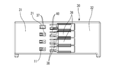
- FIG. 1 is an exploded perspective view of a joint connector according to an embodiment of the present invention.
- FIG. 2 is a bottom view of the connector housing shown in FIG.
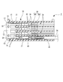
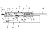
- FIG. 3 is a horizontal sectional view for explaining a terminal half-insertion inspection process when inserting the female terminal fitting into the connector housing shown in FIG.
- FIG. 4 is a longitudinal sectional view for explaining a terminal half-insertion inspection process when the female terminal fitting is inserted into the connector housing shown in FIG.
- FIG. 5 is a longitudinal sectional view for explaining a terminal half insertion inspection process when inserting the female terminal fitting into the connector housing shown in FIG.
- FIG. 6 is a longitudinal sectional view for explaining a terminal half-insertion inspection process when a female terminal fitting is inserted into the connector housing shown in FIG.
- FIG. 1 is an exploded perspective view of a joint connector according to an embodiment of the present invention.
- FIG. 2 is a bottom view of the connector housing shown in FIG.
- FIG. 3 is a horizontal sectional view for explaining a terminal half-
- FIG. 7 is a horizontal sectional view for explaining a terminal half-insertion inspection process when a female terminal fitting is inserted into the connector housing shown in FIG.
- FIG. 8 is a longitudinal sectional view of a conventional joint connector.
- FIG. 9 is a longitudinal sectional view of another conventional joint connector.
- the joint connector 1 of this embodiment is provided with the joint terminal 10, the female terminal metal fitting 20, and the connector housing 30, as shown in FIG.
- the joint terminal 10 is a press-formed product of a metal plate, and a plurality of (four in the present embodiment) tab pieces 11 for fitting and connecting the female terminal fitting 20 and a connection in which these tab pieces 11 are electrically connected.
- the part 12 is integrally formed.
- a pair of wedge-shaped main locking projections 13 and a pair of wedge-shaped temporary locking projections 14 projecting forward from the main locking projections 13 are integrally formed on both side edges of the connecting portion 12. Yes.
- the female terminal fitting 20 is a press-molded product of a metal plate. As shown in FIG. 1, the rectangular tube-shaped box part (electrical connection part) 21 into which the tab piece 11 is fitted, An electric wire caulking portion 22 that extends from the end and crimps the electric wire 26 and a retaining portion 23 for retaining are provided.
- the electric wire crimping portion 22 includes a conductor crimping piece 22a that crimps and conducts the conductor of the electric wire 26, and a covering crimping piece 22b that fixes the electric wire 26 by crimping to the covering portion of the electric wire 26.
- the retaining locking portion 23 is a recess formed on the rear end side of the box portion 21, and is latched by a locking lance 36 of the connector housing 30, which will be described later, to prevent the female terminal fitting 20 from coming off.
- the connector housing 30 is a synthetic resin injection-molded product, and includes a housing one end portion 31 and a housing other end portion 32 that is an end portion on the opposite side of the housing one end portion 31. As shown in FIGS. 3 and 7, the housing one end portion 31 has the joint terminal 10 press-fitted with the tab piece 11 facing the housing other end portion 32 side, as shown in FIG. 3 or FIG. It is accommodated and held at a position (position in FIG. 7).
- a temporary locking recess 33 is formed on the inner wall of the housing one end 31. Therefore, the joint terminal 10 press-fitted to the temporary locking position is brought into the temporary locking position by locking a pair of temporary locking protrusions 14 protruding from both side edges of the connecting portion 12 to the temporary locking recess 33. Accurately held.
- the temporary locking recess 33 can be omitted by accurately managing the press-fitting stroke.
- a plurality of terminal accommodating chambers 34 are arranged in the housing other end 32.
- the plurality of terminal accommodating chambers 34 are configured to fit the box portion 21 of the female terminal fitting 20 and the tab piece 11 by inserting the female terminal fitting 20 to a specified position.
- the specified position is a position where the tab piece 11 and the box portion 21 held at the final locking position obtain a contact length necessary and sufficient for electrical connection.
- each terminal accommodating chamber 34 On the bottom wall of each terminal accommodating chamber 34, a locking lance 36, a tab viewing window 37, and a probe insertion opening 40 corresponding to each terminal accommodating chamber 34. And are provided. As shown in FIGS. 3 to 5, the locking lance 36 protrudes from the elastic arm 36a extending toward the housing one end 31 along the terminal accommodating chamber 34 and the inner surface of the free end of the elastic arm 36a. Terminal locking projections 36b.
- the terminal locking protrusion 36b protrudes inward of the terminal accommodating chamber 34, and as shown in FIG. 4, is engaged with the retaining locking portion 23 of the female terminal fitting 20 inserted at a specified position. By joining, the female terminal fitting 20 is prevented from coming off. As shown in FIG. 2, the tab visual recognition window portion 37 is opened at a position where the tip end portion of the tab piece 11 can be seen, and the state where the box portion 21 is fitted to the tab piece 11 can be seen. is there.
- the probe insertion opening 40 is opened to the housing one end 31 side of the locking lance 36 as shown in FIGS.
- a probe 61 on one pole side of a continuity tester 60 described later is inserted into the terminal accommodating chamber 34 from below.
- the probe insertion opening 40 according to the present embodiment is constituted by a plurality of comb-like protrusions 38 formed on a part of the bottom wall of the terminal accommodating chamber 34 so as to extend toward the housing other end 32 side. Therefore, the probe insertion opening 40 can be easily formed in the connector housing 30 by integral molding.
- the joint terminal 10 is directly held by the housing one end 31 of the connector housing 30, it is not necessary to use a joint holder or the like, and the number of parts is reduced as compared with the conventional joint connector. can do.
- the terminal half-insertion inspection device 50 is mounted on the base portion 42 on which the bottom wall of the connector housing 30 in which the probe insertion opening 40 is formed, and on the base portion 42.
- the end support surface 53 that restricts the movement of the connector housing 30 in the terminal insertion / removal direction (left-right direction in FIG. 3) by contacting the end surfaces of the housing one end 31 and the other end 32 of the connector housing 30. , 55 and a continuity tester 60.
- the continuity tester 60 is inserted into the probe insertion opening 40 and contacts the female terminal fitting 20.
- the probe 61 on the one pole side contacts the rear end of the joint terminal 10 mounted on the connector housing 30.
- a probe 63 and conducting wires connected to the probes 61 and 63 are provided.
- the one-pole probe 61 incorporated in the base portion 42 is supported so as to be able to appear and retract in the terminal accommodating chamber 34 via the probe insertion opening 40 by a vertical drive mechanism (not shown). Therefore, the continuity tester 60 can detect the continuity state between the joint terminal 10 and the female terminal fitting 20.
- the connector housing When performing the terminal half-insertion inspection when inserting the female terminal fitting 20 into the connector housing 30, first, as shown in FIG. 2, the connector housing is attached to the base portion 42 of the terminal half-insertion inspection apparatus 50. With the 30 placed, the joint terminal 10 is press-fitted to the temporary locking position of the one end 31 of the housing.
- the temporary locking position of the joint terminal 10 to be press-fitted into the housing one end portion 31 is only the female terminal fitting 20 in a state where the joint terminal 10 is inserted to the specified position of the terminal accommodating chamber 34 as shown in FIG. It is a position where conduction connection is possible, and is a press-fit position shallower than the main locking position. That is, the female terminal fitting 20 that is not inserted to the specified position of the terminal accommodating chamber 34 is not conductively connected to the joint terminal 10.
- the connector housing 30 in a state where the joint terminal 10 is press-fitted in the housing one end portion 31 to the temporary locking position in advance may be placed on the base portion 42 of the terminal half insertion inspection device 50.
- the female terminal fitting 20 is connected to the terminal while the joint terminal 10 is held at the temporary locking position of the housing one end 31 that is shallower than the final locking position. Then, the joint terminal 10 is displaced to the final locking position, and the tab piece 11 and the female terminal fitting 20 are brought into a proper fitting state. Therefore, when the female terminal fitting 20 is inserted into the terminal accommodating chamber 34, the terminal fitting force can be kept low because the female fitting 20 is not in a proper fitting state where all the insertion force of the tab piece 11 is applied.
- the probe 61 on one pole side of the continuity tester 60 is connected to the probe insertion opening 40 with respect to the connector housing 30 placed on the base portion 42 of the terminal half insertion inspection device 50. Is inserted into the terminal accommodating chamber 34 and brought into contact with the female terminal fitting 20 inserted into the terminal accommodating chamber 34. Furthermore, the probe 63 on the other pole side is brought into contact with the rear end of the joint terminal 10.
- the continuity tester 60 detects the continuity between the female terminal fitting 20 inserted into the terminal accommodating chamber 34 and the joint terminal 10. At this time, as shown in FIG. 3, the female terminal fitting 20 is inserted to the specified position of the terminal accommodating chamber 34, and the box portion 21 and the tab piece 11 have obtained a contact length necessary and sufficient for electrical connection. If in the fitted state, the continuity tester 60 detects the continuity state. Therefore, the terminal complete insertion state of the female terminal fitting 20 can be detected.
- the continuity tester 60 detects a non-conduction state. Accordingly, it is possible to detect the terminal half-inserted state of the female terminal fitting 20. Then, the female terminal fitting 20 in which the terminal half-insertion state is detected is inserted into the specified position and the insertion operation is repeated until the continuity tester 60 detects the continuity state.
- the rear end of the joint terminal 10 is pressed and urged by the terminal pressing jig 70 against the joint connector 1 in which the terminal complete insertion state of the female terminal fitting 20 is detected.
- the joint terminal 10 is press-fitted to the main locking position of the housing one end 31.
- the joint terminal 10 that has been press-fitted to the final locking position is double-locked by the final locking protrusion 13 and the temporary locking protrusion 14, so that the joint terminal 10 is securely held by the one end 31 of the housing.
- the joint terminal 10 is press-fitted to the main locking position of the housing one end portion 31, the box portion 21 and the tab piece 11 are properly fitted as shown in FIG. 6, and the assembly of the joint connector 1 is completed. .
- the joint terminal 10 can be held at the temporary locking position of the housing one end portion 31 shallower than the main locking position at the time of assembly. Then, with the joint terminal 10 held in the temporary locking position, the female terminal fitting 20 is inserted to the specified position of the terminal accommodating chamber 34, and then the joint terminal 10 is displaced to the final locking position to bring the tab piece 11 into place. And the female terminal metal fitting 20 can be made into a regular fitting state. Therefore, when the female terminal fitting 20 is inserted into the terminal accommodating chamber 34, the terminal fitting force can be kept low because the female fitting 20 is not in a proper fitting state where all the insertion force of the tab piece 11 is applied.
- the joint terminal 10 when assembling the joint connector 1, the joint terminal 10 is held in the temporary locking position at the one end 31 of the housing, and then the joint terminal 10 is inserted in a state where the female terminal fitting 20 is inserted to the specified position in the terminal accommodating chamber 34. And the female terminal fitting 20 can be inspected for continuity. Therefore, when the joint terminal 10 and the female terminal fitting 20 are non-conducting, the terminal half insertion of the female terminal fitting 20 can be detected, so that the terminal half insertion of the female terminal fitting 20 can be prevented. .
- the configurations of the female terminal fitting, the joint terminal, the main locking projection, the temporary locking projection, the connector housing, the temporary locking recess, the box portion, the probe insertion opening, and the like related to the joint connector of the present invention are the configurations of the above embodiment. Needless to say, the present invention is not limited to the above, and various forms can be adopted based on the gist of the present invention.
Landscapes
- Physics & Mathematics (AREA)
- General Physics & Mathematics (AREA)
- Manufacturing Of Electrical Connectors (AREA)
- Details Of Connecting Devices For Male And Female Coupling (AREA)
- Connector Housings Or Holding Contact Members (AREA)
Abstract
ジョイント端子(10)は、収容されるハウジング一端部(31)における、タブ片(11)が端子収容室(34)に挿入された雌型端子金具(20)に導通接続可能な正規の嵌合状態となる本係止位置と、端子収容室(34)の規定位置まで挿入された状態の雌型端子金具(20)にだけ導通接続可能な本係止位置よりも浅い仮係止位置とに保持可能とされる。
Description
本発明は、端子半挿入を検知できるジョイントコネクタ及びそのジョイントコネクタを用いた端子半挿入検査方法に関する。
例えば自動車用ワイヤハーネスの分岐接続に用いられる従来のジョイントコネクタとしては、特許文献1等に記載されたものが知られている。このジョイントコネクタ100は、図8に示すように、複数の雌側端子金具(雌型端子金具)140を収容する雌側コネクタハウジング(コネクタハウジング)120と、各雌側端子金具140に連結されるジョイント端子132を備えたジョイントハウジング130とを備えている。
これら雌側コネクタハウジング120とジョイントハウジング130の嵌合状態には、雌側コネクタハウジング120に対して浅く嵌合する仮嵌合状態と、これよりも深く嵌合して雌側端子金具140とジョイント端子132のタブ(タブ片)134とが接続する本嵌合状態の2つの嵌合状態が設けられている。
そして、両ハウジング120,130の仮嵌合状態から本嵌合状態に移行させる際、雌側端子金具140が正規位置に達していない半挿入状態にあった場合には、ランス122が撓み空間123に弾性変形した状態にあるため、ジョイントハウジング130に設けた撓み規制部136の先端がランス122に当接し、それ以上の挿入ができない。これにより雌側端子金具140の半挿入状態が検知されるように構成されている。
また、特許文献2等に記載されたジョイントコネクタ200は、図9に示すように、雌端子金具(雌型端子金具)210と、雌端子金具210が収容されるコネクタハウジング220と、雌端子金具210同士を短絡するバスバー230と、バスバー230を保持する保持部材240とを備えて構成されている。
保持部材240は、コネクタハウジング220において、バスバー230のタブ片233が雌端子金具210の接続部(電気接続部)212に対し正規の接触状態となる本係止位置と非接触状態となる仮係止位置とに保持可能とされる。
そして、保持部材240を仮係止位置から本係止規制位置へ変位する途中で、タブ片233が半挿入状態の雌端子金具210の接続部212に当接した場合には、その当接感によって、半挿入状態の雌端子金具210が存在することを知ることができるように構成されている。
保持部材240は、コネクタハウジング220において、バスバー230のタブ片233が雌端子金具210の接続部(電気接続部)212に対し正規の接触状態となる本係止位置と非接触状態となる仮係止位置とに保持可能とされる。
そして、保持部材240を仮係止位置から本係止規制位置へ変位する途中で、タブ片233が半挿入状態の雌端子金具210の接続部212に当接した場合には、その当接感によって、半挿入状態の雌端子金具210が存在することを知ることができるように構成されている。
しかしながら、上述した従来のジョイントコネクタは、いずれもジョイント端子を合成樹脂製のジョイントハウジングや保持部材に保持させておき、ジョイント端子の抜き差しはジョイントハウジングや保持部材をコネクタハウジングに組み付けたり、外したりすることで行うように構成されている。
そこで、合成樹脂製のジョイントハウジングや保持部材が必要となり、部品点数が多くなるという問題があった。
そこで、合成樹脂製のジョイントハウジングや保持部材が必要となり、部品点数が多くなるという問題があった。
また、これら従来のジョイントコネクタにおける雌型端子金具の半挿入状態検知は、ジョイントハウジングや保持部材を本嵌合状態や本係止位置に変位させた際の作業者の当接感や目視により行われている。
そこで、極数が多くなると、ジョイントハウジングや保持部材を本嵌合状態や本係止位置に変位させる際の操作力が高まる一方で当接感が弱まり、作業者が感覚的に確認し難くなる。そのため、これら従来のジョイントコネクタにおいては、端子の半挿入状態を誤検知する可能性があるという問題があった。
そこで、極数が多くなると、ジョイントハウジングや保持部材を本嵌合状態や本係止位置に変位させる際の操作力が高まる一方で当接感が弱まり、作業者が感覚的に確認し難くなる。そのため、これら従来のジョイントコネクタにおいては、端子の半挿入状態を誤検知する可能性があるという問題があった。
本発明は、上述した事情に鑑みてなされたものであり、その目的は、部品点数が少なくて済み、更に端子半挿入を確実に検知することができるジョイントコネクタ及び端子半挿入検査方法を提供することにある。
前述した目的を達成するために、本発明に係るジョイントコネクタ及び端子半挿入検査方法は、下記(1)~(4)を特徴としている。
(1) 複数本の雌型端子金具と、
前記雌型端子金具を嵌合接続する複数本のタブ片とこれらのタブ片を導通接続した連結部とを備えたジョイント端子と、
前記タブ片をハウジングの他端側に向けて前記ジョイント端子を収容保持するハウジング一端部と、前記雌型端子金具を規定位置まで挿入することで前記雌型端子金具と前記タブ片とを嵌合状態にする複数の端子収容室が配設されたハウジング他端部と、を有する合成樹脂製のコネクタハウジングと、を備え、
前記ジョイント端子は、前記ハウジング一端部における、前記タブ片が前記端子収容室に挿入された前記雌型端子金具に導通接続可能な正規の嵌合状態となる本係止位置と、前記端子収容室の規定位置まで挿入された状態の前記雌型端子金具にだけ導通接続可能な前記本係止位置よりも浅い仮係止位置とに保持可能とされるジョイントコネクタ。
(2) 上記(1)の構成のジョイントコネクタにおいて、
前記ジョイント端子は、前記連結部に突設されて前記ハウジング一端部に係止される本係止突起と、前記本係止突起よりも前記タブ片側の前記連結部に突設されて前記ハウジング一端部に係止される仮係止突起とを備えること。
(3) 上記(2)の構成のジョイントコネクタにおいて、
前記ハウジング一端部は、前記仮係止突起を係止して前記ジョイント端子を前記仮係止位置に保持する仮係止凹部を備えること。
(4) 上記(1)~(3)の何れか1つの構成のジョイントコネクタを用いた端子半挿入検査方法であって、
前記ジョイント端子を前記ハウジング一端部に対して前記仮係止位置に保持させた後、前記雌型端子金具を前記端子収容室の前記規定位置まで挿入した状態で前記ジョイント端子と前記雌型端子金具とを導通検査し、これらジョイント端子と雌型端子金具とが非導通時を端子半挿入として検知すること。
(1) 複数本の雌型端子金具と、
前記雌型端子金具を嵌合接続する複数本のタブ片とこれらのタブ片を導通接続した連結部とを備えたジョイント端子と、
前記タブ片をハウジングの他端側に向けて前記ジョイント端子を収容保持するハウジング一端部と、前記雌型端子金具を規定位置まで挿入することで前記雌型端子金具と前記タブ片とを嵌合状態にする複数の端子収容室が配設されたハウジング他端部と、を有する合成樹脂製のコネクタハウジングと、を備え、
前記ジョイント端子は、前記ハウジング一端部における、前記タブ片が前記端子収容室に挿入された前記雌型端子金具に導通接続可能な正規の嵌合状態となる本係止位置と、前記端子収容室の規定位置まで挿入された状態の前記雌型端子金具にだけ導通接続可能な前記本係止位置よりも浅い仮係止位置とに保持可能とされるジョイントコネクタ。
(2) 上記(1)の構成のジョイントコネクタにおいて、
前記ジョイント端子は、前記連結部に突設されて前記ハウジング一端部に係止される本係止突起と、前記本係止突起よりも前記タブ片側の前記連結部に突設されて前記ハウジング一端部に係止される仮係止突起とを備えること。
(3) 上記(2)の構成のジョイントコネクタにおいて、
前記ハウジング一端部は、前記仮係止突起を係止して前記ジョイント端子を前記仮係止位置に保持する仮係止凹部を備えること。
(4) 上記(1)~(3)の何れか1つの構成のジョイントコネクタを用いた端子半挿入検査方法であって、
前記ジョイント端子を前記ハウジング一端部に対して前記仮係止位置に保持させた後、前記雌型端子金具を前記端子収容室の前記規定位置まで挿入した状態で前記ジョイント端子と前記雌型端子金具とを導通検査し、これらジョイント端子と雌型端子金具とが非導通時を端子半挿入として検知すること。
上記(1)の構成のジョイントコネクタによれば、ジョイント端子がコネクタハウジングのハウジング一端部に直接保持されるので、部品点数を削減することができる。
また、上記ジョイントコネクタの組立時には、ジョイント端子を本係止位置よりも浅いハウジング一端部の仮係止位置に保持することができる。そして、ジョイント端子を仮係止位置に保持した状態で、雌型端子金具を端子収容室の規定位置まで挿入し、その後、ジョイント端子を本係止位置に変位させてタブ片と雌型端子金具を正規の嵌合状態とすることができる。そこで、雌型端子金具は、端子収容室に挿入される際にはタブ片の挿入力が全て加わる正規の嵌合状態とはならないので、端子挿入力を低く抑えることができる。
更に、上記ジョイントコネクタの組立時には、ジョイント端子をハウジング一端部における仮係止位置に保持させた後、雌型端子金具を端子収容室の規定位置まで挿入した状態でジョイント端子と雌型端子金具とを導通検査することができる。そこで、これらジョイント端子と雌型端子金具とが非導通時には、雌型端子金具の端子半挿入を検知することができるので、雌型端子金具の端子半挿入を防止することができる。
上記(2)の構成のジョイントコネクタによれば、形成が容易で簡単な形状の本係止突起及び仮係止突起によって、ジョイント端子をハウジング一端部において本係止位置又は仮係止位置に確実に保持することができる。特に、本係止位置においては、本係止突起及び仮係止突起により二重に係止できる。
上記(3)の構成のジョイントコネクタによれば、仮係止突起を仮係止凹部に係止させることによって、ジョイント端子を仮係止位置に正確に保持させることができる。
上記(4)の構成の端子半挿入検査方法によれば、上記(1)~(3)の何れか1つの構成のジョイントコネクタにおけるジョイント端子を仮係止位置に保持させた後、端子収容室に挿入した雌型端子金具とジョイント端子の非導通を検出することによって、雌型端子金具の端子半挿入を検知することができる。そこで、部品点数が少ない簡単な構造でありながら、雌型端子金具の端子半挿入を確実に防止することができる。
また、上記ジョイントコネクタの組立時には、ジョイント端子を本係止位置よりも浅いハウジング一端部の仮係止位置に保持することができる。そして、ジョイント端子を仮係止位置に保持した状態で、雌型端子金具を端子収容室の規定位置まで挿入し、その後、ジョイント端子を本係止位置に変位させてタブ片と雌型端子金具を正規の嵌合状態とすることができる。そこで、雌型端子金具は、端子収容室に挿入される際にはタブ片の挿入力が全て加わる正規の嵌合状態とはならないので、端子挿入力を低く抑えることができる。
更に、上記ジョイントコネクタの組立時には、ジョイント端子をハウジング一端部における仮係止位置に保持させた後、雌型端子金具を端子収容室の規定位置まで挿入した状態でジョイント端子と雌型端子金具とを導通検査することができる。そこで、これらジョイント端子と雌型端子金具とが非導通時には、雌型端子金具の端子半挿入を検知することができるので、雌型端子金具の端子半挿入を防止することができる。
上記(2)の構成のジョイントコネクタによれば、形成が容易で簡単な形状の本係止突起及び仮係止突起によって、ジョイント端子をハウジング一端部において本係止位置又は仮係止位置に確実に保持することができる。特に、本係止位置においては、本係止突起及び仮係止突起により二重に係止できる。
上記(3)の構成のジョイントコネクタによれば、仮係止突起を仮係止凹部に係止させることによって、ジョイント端子を仮係止位置に正確に保持させることができる。
上記(4)の構成の端子半挿入検査方法によれば、上記(1)~(3)の何れか1つの構成のジョイントコネクタにおけるジョイント端子を仮係止位置に保持させた後、端子収容室に挿入した雌型端子金具とジョイント端子の非導通を検出することによって、雌型端子金具の端子半挿入を検知することができる。そこで、部品点数が少ない簡単な構造でありながら、雌型端子金具の端子半挿入を確実に防止することができる。
本発明によれば、部品点数が少なくて済み、更に端子半挿入を確実に検知することができるジョイントコネクタ及び端子半挿入検査方法を提供できる。
以上、本発明について簡潔に説明した。更に、以下に説明される発明を実施するための形態(以下、「実施形態」という。)を添付の図面を参照して通読することにより、本発明の詳細は更に明確化されるであろう。
以下、添付図面に基づいて本発明の一実施形態に係るジョイントコネクタを詳細に説明する。
本実施形態のジョイントコネクタ1は、図1に示すように、ジョイント端子10と、雌型端子金具20と、コネクタハウジング30と、を備える。
ジョイント端子10は、金属板のプレス成形品であり、雌型端子金具20を嵌合接続する複数本(本実施形態では4本)のタブ片11と、これらのタブ片11を導通接続した連結部12とが一体成形されている。更に、連結部12の両側縁には、一対の楔状の本係止突起13と、本係止突起13より前端側に突設された一対の楔状の仮係止突起14とが一体成形されている。
本実施形態のジョイントコネクタ1は、図1に示すように、ジョイント端子10と、雌型端子金具20と、コネクタハウジング30と、を備える。
ジョイント端子10は、金属板のプレス成形品であり、雌型端子金具20を嵌合接続する複数本(本実施形態では4本)のタブ片11と、これらのタブ片11を導通接続した連結部12とが一体成形されている。更に、連結部12の両側縁には、一対の楔状の本係止突起13と、本係止突起13より前端側に突設された一対の楔状の仮係止突起14とが一体成形されている。
雌型端子金具20は、金属板のプレス成形品であり、図1に示すように、タブ片11が嵌合する角筒状の箱部(電気接続部)21と、該箱部21の後端から延出して電線26を圧着する電線加締め部22と、抜け止め用係止部23とを備える。
電線加締め部22は、電線26の導体を圧着して導通させる導体加締め片22aと、電線26の被覆部に加締め付けることで電線26を固定する被覆加締め片22bとを備える。
抜け止め用係止部23は、箱部21の後端側に形成された凹部であり、後述するコネクタハウジング30の係止用ランス36に係止され、雌型端子金具20を抜け止めする。
抜け止め用係止部23は、箱部21の後端側に形成された凹部であり、後述するコネクタハウジング30の係止用ランス36に係止され、雌型端子金具20を抜け止めする。
コネクタハウジング30は、合成樹脂の射出成形品であり、ハウジング一端部31と、該ハウジング一端部31とは反対側の端部であるハウジング他端部32とを備えている。
ハウジング一端部31は、図3及び図7に示すように、タブ片11をハウジング他端部32側に向けて圧入されたジョイント端子10を仮係止位置(図3の位置)又は本係止位置(図7の位置)に収容保持する。
ハウジング一端部31は、図3及び図7に示すように、タブ片11をハウジング他端部32側に向けて圧入されたジョイント端子10を仮係止位置(図3の位置)又は本係止位置(図7の位置)に収容保持する。
尚、本実施形態に係るコネクタハウジング30においては、ハウジング一端部31の内側壁に仮係止凹部33が形成されている。そこで、仮係止位置まで圧入されたジョイント端子10は、連結部12の両側縁に突設した一対の仮係止突起14を仮係止凹部33に係止させることによって、仮係止位置に正確に保持される。勿論、圧入ストロークを正確に管理することで、仮係止凹部33を省略することもできる。
ハウジング他端部32には、図3に示すように、複数の端子収容室34が並設されている。これら複数の端子収容室34は、雌型端子金具20を規定位置まで挿入することで雌型端子金具20の箱部21とタブ片11とを嵌合状態にする。ここで、規定位置とは、本係止位置に保持されたタブ片11と箱部21とが、電気的な接続に必要十分な接触長を得る位置である。
各端子収容室34の底壁には、図2及び図3に示すように、各端子収容室34に対応して、係止用ランス36と、タブ視認用窓部37と、プローブ挿入開口40とが設けられている。
係止用ランス36は、図3~図5に示すように、端子収容室34に沿ってハウジング一端部31側に延出する弾性アーム36aと、この弾性アーム36aの自由端内面に突設された端子係止用突起36bとを備えている。
係止用ランス36は、図3~図5に示すように、端子収容室34に沿ってハウジング一端部31側に延出する弾性アーム36aと、この弾性アーム36aの自由端内面に突設された端子係止用突起36bとを備えている。
端子係止用突起36bは、端子収容室34の内方に向かって突出しており、図4に示すように、規定位置に挿入された雌型端子金具20の抜け止め用係止部23に係合することで、雌型端子金具20を抜け止めする。
タブ視認用窓部37は、図2に示すように、タブ片11の先端部を目視できる位置に開口しており、タブ片11に箱部21が嵌合した状態を目視することが可能である。
タブ視認用窓部37は、図2に示すように、タブ片11の先端部を目視できる位置に開口しており、タブ片11に箱部21が嵌合した状態を目視することが可能である。
プローブ挿入開口40は、図2及び図3に示すように、係止用ランス36のハウジング一端部31側に開口されている。そして、プローブ挿入開口40には、後述する導通検査機60の一極側のプローブ61が下方から端子収容室34内に挿入される。
本実施形態に係るプローブ挿入開口40は、ハウジング他端部32側に延びるように端子収容室34の底壁の一部に形成された複数の櫛状突起38により構成されている。そこで、一体成形によりプローブ挿入開口40をコネクタハウジング30に容易に形成することができる。
本実施形態に係るジョイントコネクタ1によれば、ジョイント端子10がコネクタハウジング30のハウジング一端部31に直接保持されるので、ジョイントホルダ等を用いる必要がなく、従来のジョイントコネクタよりも部品点数を削減することができる。
次に、図3~図7を参照しながら、端子半挿入検査装置50を用いてコネクタハウジング30に雌型端子金具20を挿入する際の端子半挿入検査工程を説明する。
端子半挿入検査装置50は、図3~図5に示すように、プローブ挿入開口40を形成されたコネクタハウジング30の底壁が載置される基台部42と、基台部42に載置されたコネクタハウジング30のハウジング一端部31及びハウジング他端部32の端面にそれぞれ当接して端子挿脱方向(図3中、左右方向)へのコネクタハウジング30の移動を規制する端部支持面53,55と、導通検査機60とを備えている。
端子半挿入検査装置50は、図3~図5に示すように、プローブ挿入開口40を形成されたコネクタハウジング30の底壁が載置される基台部42と、基台部42に載置されたコネクタハウジング30のハウジング一端部31及びハウジング他端部32の端面にそれぞれ当接して端子挿脱方向(図3中、左右方向)へのコネクタハウジング30の移動を規制する端部支持面53,55と、導通検査機60とを備えている。
導通検査機60は、プローブ挿入開口40に挿入されて雌型端子金具20に当接する一極側のプローブ61と、コネクタハウジング30に装着されたジョイント端子10の後端に当接する他極側のプローブ63と、これらプローブ61,63にそれぞれ接続される導線とを備える。尚、基台部42内に組み込まれた一極側のプローブ61は、図示しない上下駆動機構によりプローブ挿入開口40を介して端子収容室34内に出没可能に支持されている。
そこで、導通検査機60は、ジョイント端子10と雌型端子金具20との導通状態を検知することができる。
そこで、導通検査機60は、ジョイント端子10と雌型端子金具20との導通状態を検知することができる。
そして、コネクタハウジング30に雌型端子金具20を挿入する際の端子半挿入検査を行う際には、先ず、図2に示したように、端子半挿入検査装置50の基台部42にコネクタハウジング30を載置した状態で、ジョイント端子10をハウジング一端部31の仮係止位置まで圧入する。
ここで、ハウジング一端部31に圧入されるジョイント端子10の仮係止位置とは、図3に示したように、端子収容室34の規定位置まで挿入された状態の雌型端子金具20にだけ導通接続可能な位置であり、本係止位置よりも浅い圧入位置である。即ち、端子収容室34の規定位置まで挿入されていない状態の雌型端子金具20は、ジョイント端子10と導通接続されない。
尚、予めジョイント端子10がハウジング一端部31に仮係止位置まで圧入された状態のコネクタハウジング30を端子半挿入検査装置50の基台部42に載置してもよい。
尚、予めジョイント端子10がハウジング一端部31に仮係止位置まで圧入された状態のコネクタハウジング30を端子半挿入検査装置50の基台部42に載置してもよい。
上述したように、本実施形態に係るジョイントコネクタ1の組立時には、ジョイント端子10を本係止位置よりも浅いハウジング一端部31の仮係止位置に保持した状態で、雌型端子金具20を端子収容室34の規定位置まで挿入し、その後、ジョイント端子10を本係止位置に変位させてタブ片11と雌型端子金具20を正規の嵌合状態とする。
そこで、雌型端子金具20は、端子収容室34に挿入される際にはタブ片11の挿入力が全て加わる正規の嵌合状態とはならないので、端子挿入力を低く抑えることができる。
そこで、雌型端子金具20は、端子収容室34に挿入される際にはタブ片11の挿入力が全て加わる正規の嵌合状態とはならないので、端子挿入力を低く抑えることができる。
次に、図3に示したように、端子半挿入検査装置50の基台部42に載置されたコネクタハウジング30に対して、導通検査機60の一極側のプローブ61をプローブ挿入開口40から端子収容室34内に挿入し、端子収容室34に挿入された雌型端子金具20に当接させる。更に、他極側のプローブ63をジョイント端子10の後端に当接させる。
そして、導通検査機60によって、端子収容室34に挿入した雌型端子金具20とジョイント端子10の導通状態を検出する。
この時、図3に示したように、雌型端子金具20が端子収容室34の規定位置まで挿入され、箱部21とタブ片11とが電気的な接続に必要十分な接触長を得た嵌合状態であれば、導通検査機60は導通状態を検出する。従って、雌型端子金具20の端子完全挿入状態を検知することができる。
この時、図3に示したように、雌型端子金具20が端子収容室34の規定位置まで挿入され、箱部21とタブ片11とが電気的な接続に必要十分な接触長を得た嵌合状態であれば、導通検査機60は導通状態を検出する。従って、雌型端子金具20の端子完全挿入状態を検知することができる。
また、図4に示したように、雌型端子金具20が端子収容室34の規定位置まで挿入されておらず、箱部21とタブ片11とが電気的に接続されていない状態であれば、導通検査機60は非導通状態を検出する。従って、雌型端子金具20の端子半挿入状態を検知することができる。
そして、端子半挿入状態を検知された雌型端子金具20は、規定位置に挿入されて導通検査機60が導通状態を検出するまで、挿入動作を繰り返す。
そして、端子半挿入状態を検知された雌型端子金具20は、規定位置に挿入されて導通検査機60が導通状態を検出するまで、挿入動作を繰り返す。
次に、図5に示したように、雌型端子金具20の端子完全挿入状態が検知されたジョイントコネクタ1に対して、端子押圧治具70によりジョイント端子10の後端を押圧付勢し、該ジョイント端子10をハウジング一端部31の本係止位置まで圧入する。尚、本係止位置まで圧入されたジョイント端子10は、本係止突起13及び仮係止突起14により二重に係止されるので、ハウジング一端部31に確実に保持される。
ジョイント端子10がハウジング一端部31の本係止位置まで圧入されると、図6に示すように、箱部21とタブ片11とが正規の嵌合状態となり、ジョイントコネクタ1の組立が完了する。
ジョイント端子10がハウジング一端部31の本係止位置まで圧入されると、図6に示すように、箱部21とタブ片11とが正規の嵌合状態となり、ジョイントコネクタ1の組立が完了する。
従って、上述した本実施形態に係るジョイントコネクタ1によれば、組み立て時には、ジョイント端子10を本係止位置よりも浅いハウジング一端部31の仮係止位置に保持することができる。そして、ジョイント端子10を仮係止位置に保持した状態で、雌型端子金具20を端子収容室34の規定位置まで挿入し、その後、ジョイント端子10を本係止位置に変位させてタブ片11と雌型端子金具20を正規の嵌合状態とすることができる。そこで、雌型端子金具20は、端子収容室34に挿入される際にはタブ片11の挿入力が全て加わる正規の嵌合状態とはならないので、端子挿入力を低く抑えることができる。
また、ジョイントコネクタ1を組み立てる際に、ジョイント端子10をハウジング一端部31における仮係止位置に保持させた後、雌型端子金具20を端子収容室34の規定位置まで挿入した状態でジョイント端子10と雌型端子金具20とを導通検査することができる。そこで、これらジョイント端子10と雌型端子金具20とが非導通時には、雌型端子金具20の端子半挿入を検知することができるので、雌型端子金具20の端子半挿入を防止することができる。
尚、本発明のジョイントコネクタに係る雌端子金具、ジョイント端子、本係止突起、仮係止突起、コネクタハウジング、仮係止凹部、箱部及びプローブ挿入開口等の構成は、上記実施形態の構成に限定されるものではなく、本発明の主旨に基づいて種々の形態を採りうることは云うまでもない。
本発明を詳細にまた特定の実施態様を参照して説明したが、本発明の精神と範囲を逸脱することなく様々な変更や修正を加えることができることは当業者にとって明らかである。
本出願は、2011年2月18日出願の日本特許出願(特願2011-033712)に基づくものであり、その内容はここに参照として取り込まれる。
本発明によれば、部品点数が少なくて済み、更に端子半挿入を確実に検知することができるジョイントコネクタ及び端子半挿入検査方法を提供できる。
1 ジョイントコネクタ
10 ジョイント端子
11 タブ片
12 連結部
13 本係止突起
14 仮係止突起
20 雌型端子金具
21 箱部
30 コネクタハウジング
33 仮係止凹部
40 プローブ挿入開口
10 ジョイント端子
11 タブ片
12 連結部
13 本係止突起
14 仮係止突起
20 雌型端子金具
21 箱部
30 コネクタハウジング
33 仮係止凹部
40 プローブ挿入開口
Claims (4)
- 複数本の雌型端子金具と、
前記雌型端子金具を嵌合接続する複数本のタブ片とこれらのタブ片を導通接続した連結部とを備えたジョイント端子と、
前記タブ片をハウジングの他端側に向けて前記ジョイント端子を収容保持するハウジング一端部と、前記雌型端子金具を規定位置まで挿入することで前記雌型端子金具と前記タブ片とを嵌合状態にする複数の端子収容室が配設されたハウジング他端部と、を有する合成樹脂製のコネクタハウジングと、を備え、
前記ジョイント端子は、前記ハウジング一端部における、前記タブ片が前記端子収容室に挿入された前記雌型端子金具に導通接続可能な正規の嵌合状態となる本係止位置と、前記端子収容室の規定位置まで挿入された状態の前記雌型端子金具にだけ導通接続可能な前記本係止位置よりも浅い仮係止位置とに保持可能とされるジョイントコネクタ。 - 前記ジョイント端子は、前記連結部に突設されて前記ハウジング一端部に係止される本係止突起と、前記本係止突起よりも前記タブ片側の前記連結部に突設されて前記ハウジング一端部に係止される仮係止突起とを備える請求項1に記載のジョイントコネクタ。
- 前記ハウジング一端部は、前記仮係止突起を係止して前記ジョイント端子を前記仮係止位置に保持する前記仮係止凹部を備える請求項2に記載のジョイントコネクタ。
- 請求項1~請求項3の何れか1項に記載されたジョイントコネクタを用いた端子半挿入検査方法であって、
前記ジョイント端子を前記ハウジング一端部に対して前記仮係止位置に保持させた後、前記雌型端子金具を前記端子収容室の前記規定位置まで挿入した状態で前記ジョイント端子と前記雌型端子金具とを導通検査し、これらジョイント端子と雌型端子金具とが非導通時を端子半挿入として検知する端子半挿入検査方法。
Priority Applications (3)
| Application Number | Priority Date | Filing Date | Title |
|---|---|---|---|
| CN201280009492XA CN103380548A (zh) | 2011-02-18 | 2012-02-10 | 接合连接器和端子部分插入检查方法 |
| DE112012000870T DE112012000870T5 (de) | 2011-02-18 | 2012-02-10 | Kammverbinder und Verfahren zum Prüfen auf unvollständige Einführung von Anschlüssen |
| US13/955,670 US20130316593A1 (en) | 2011-02-18 | 2013-07-31 | Joint Connector and Method for Testing for Partial Terminal Insertion |
Applications Claiming Priority (2)
| Application Number | Priority Date | Filing Date | Title |
|---|---|---|---|
| JP2011-033712 | 2011-02-18 | ||
| JP2011033712A JP2012174431A (ja) | 2011-02-18 | 2011-02-18 | ジョイントコネクタ及び端子半挿入検査方法 |
Related Child Applications (1)
| Application Number | Title | Priority Date | Filing Date |
|---|---|---|---|
| US13/955,670 Continuation US20130316593A1 (en) | 2011-02-18 | 2013-07-31 | Joint Connector and Method for Testing for Partial Terminal Insertion |
Publications (1)
| Publication Number | Publication Date |
|---|---|
| WO2012111571A1 true WO2012111571A1 (ja) | 2012-08-23 |
Family
ID=46672495
Family Applications (1)
| Application Number | Title | Priority Date | Filing Date |
|---|---|---|---|
| PCT/JP2012/053170 Ceased WO2012111571A1 (ja) | 2011-02-18 | 2012-02-10 | ジョイントコネクタ及び端子半挿入検査方法 |
Country Status (6)
| Country | Link |
|---|---|
| US (1) | US20130316593A1 (ja) |
| JP (1) | JP2012174431A (ja) |
| CN (1) | CN103380548A (ja) |
| DE (1) | DE112012000870T5 (ja) |
| TW (1) | TWI435500B (ja) |
| WO (1) | WO2012111571A1 (ja) |
Cited By (1)
| Publication number | Priority date | Publication date | Assignee | Title |
|---|---|---|---|---|
| CN111326915A (zh) * | 2018-12-17 | 2020-06-23 | 泰连公司 | 包括成型闩锁的插头连接器 |
Families Citing this family (9)
| Publication number | Priority date | Publication date | Assignee | Title |
|---|---|---|---|---|
| JP6141612B2 (ja) * | 2012-09-21 | 2017-06-07 | 矢崎総業株式会社 | コネクタ |
| JP6284344B2 (ja) * | 2013-11-13 | 2018-02-28 | 古河電気工業株式会社 | 挿入作業補助装置及び挿入作業補助方法 |
| JP6206392B2 (ja) * | 2014-12-25 | 2017-10-04 | 株式会社オートネットワーク技術研究所 | ジョイントコネクタ |
| JP2016207487A (ja) * | 2015-04-23 | 2016-12-08 | 株式会社オートネットワーク技術研究所 | ジョイントコネクタ |
| CN105717332A (zh) * | 2016-04-06 | 2016-06-29 | 江苏雷特电机股份有限公司 | 一种电抗器连接装置 |
| JP6727580B2 (ja) * | 2016-06-10 | 2020-07-22 | 日本圧着端子製造株式会社 | コネクタ用端子保持部材、コネクタ、及び電気的接続装置 |
| CN109186448B (zh) * | 2018-10-13 | 2020-06-16 | 西安航天动力测控技术研究所 | 一种落销深度测试仪 |
| US11251560B2 (en) * | 2019-03-11 | 2022-02-15 | TE Connectivity Services Gmbh | Terminal position assurance member with multiple latches |
| JP7088110B2 (ja) * | 2019-03-28 | 2022-06-21 | 株式会社オートネットワーク技術研究所 | ジョイントコネクタ |
Citations (4)
| Publication number | Priority date | Publication date | Assignee | Title |
|---|---|---|---|---|
| JP2000243502A (ja) * | 1999-02-16 | 2000-09-08 | Sumitomo Wiring Syst Ltd | ジョイントコネクタ |
| JP2006253017A (ja) * | 2005-03-11 | 2006-09-21 | Sumitomo Wiring Syst Ltd | ジョイントコネクタ |
| JP2007012451A (ja) * | 2005-06-30 | 2007-01-18 | Sumitomo Wiring Syst Ltd | ジョイントコネクタ |
| WO2009078374A1 (ja) * | 2007-12-18 | 2009-06-25 | Autonetworks Technologies, Ltd. | ジョイントコネクタ及びこれを用いた電線短絡方法 |
Family Cites Families (3)
| Publication number | Priority date | Publication date | Assignee | Title |
|---|---|---|---|---|
| DE60035730T2 (de) * | 1999-04-13 | 2008-04-30 | Sumitomo Wiring Systems, Ltd., Yokkaichi | Kombination aus Verbinder und Montageeinheit |
| JP3922180B2 (ja) | 2002-12-26 | 2007-05-30 | 住友電装株式会社 | ジョイントコネクタ |
| JP2011033712A (ja) | 2009-07-30 | 2011-02-17 | Nippon Seiki Co Ltd | 液晶表示装置 |
-
2011
- 2011-02-18 JP JP2011033712A patent/JP2012174431A/ja not_active Abandoned
-
2012
- 2012-02-10 CN CN201280009492XA patent/CN103380548A/zh active Pending
- 2012-02-10 DE DE112012000870T patent/DE112012000870T5/de not_active Withdrawn
- 2012-02-10 WO PCT/JP2012/053170 patent/WO2012111571A1/ja not_active Ceased
- 2012-02-17 TW TW101105204A patent/TWI435500B/zh not_active IP Right Cessation
-
2013
- 2013-07-31 US US13/955,670 patent/US20130316593A1/en not_active Abandoned
Patent Citations (4)
| Publication number | Priority date | Publication date | Assignee | Title |
|---|---|---|---|---|
| JP2000243502A (ja) * | 1999-02-16 | 2000-09-08 | Sumitomo Wiring Syst Ltd | ジョイントコネクタ |
| JP2006253017A (ja) * | 2005-03-11 | 2006-09-21 | Sumitomo Wiring Syst Ltd | ジョイントコネクタ |
| JP2007012451A (ja) * | 2005-06-30 | 2007-01-18 | Sumitomo Wiring Syst Ltd | ジョイントコネクタ |
| WO2009078374A1 (ja) * | 2007-12-18 | 2009-06-25 | Autonetworks Technologies, Ltd. | ジョイントコネクタ及びこれを用いた電線短絡方法 |
Cited By (2)
| Publication number | Priority date | Publication date | Assignee | Title |
|---|---|---|---|---|
| CN111326915A (zh) * | 2018-12-17 | 2020-06-23 | 泰连公司 | 包括成型闩锁的插头连接器 |
| CN111326915B (zh) * | 2018-12-17 | 2024-05-14 | 泰连公司 | 包括成型闩锁的插头连接器 |
Also Published As
| Publication number | Publication date |
|---|---|
| DE112012000870T5 (de) | 2013-11-14 |
| JP2012174431A (ja) | 2012-09-10 |
| CN103380548A (zh) | 2013-10-30 |
| TW201238160A (en) | 2012-09-16 |
| TWI435500B (zh) | 2014-04-21 |
| US20130316593A1 (en) | 2013-11-28 |
Similar Documents
| Publication | Publication Date | Title |
|---|---|---|
| JP2012174431A (ja) | ジョイントコネクタ及び端子半挿入検査方法 | |
| US8083543B2 (en) | Joint connector and wire short-circuiting method using the same | |
| CN101257167B (zh) | 连接器和连接器组件 | |
| US20020168896A1 (en) | Coupling structure for connectors with holder | |
| CN104662742B (zh) | 连接器 | |
| CN103368009B (zh) | 连接器 | |
| CN110311248B (zh) | 连接器 | |
| JP2001155810A (ja) | コネクタ | |
| CN113661611B (zh) | 连接器 | |
| US20180131117A1 (en) | Joint connector | |
| CN101785150B (zh) | 具有防尘罩的电连接器 | |
| JP4613820B2 (ja) | 端子接続構造 | |
| CN111092318B (zh) | 端子以及连接电线与端子的方法 | |
| JP6051921B2 (ja) | コネクタ検査装置 | |
| JP2015022968A (ja) | コネクタ | |
| JP2000243502A (ja) | ジョイントコネクタ | |
| JP7485201B2 (ja) | コネクタペア | |
| JP2000243514A (ja) | ジョイントコネクタ | |
| US10892582B2 (en) | Connector with upper and lower covers | |
| JP6506904B2 (ja) | コネクタ | |
| JP6644754B2 (ja) | 雌端子、および、導通検査装置 | |
| JP6309788B2 (ja) | コネクタ | |
| JP6100117B2 (ja) | コネクタ | |
| JP7567719B2 (ja) | コネクタ | |
| CN111146613B (zh) | 端子,将电线连接到端子的方法,以及夹具 |
Legal Events
| Date | Code | Title | Description |
|---|---|---|---|
| 121 | Ep: the epo has been informed by wipo that ep was designated in this application |
Ref document number: 12747058 Country of ref document: EP Kind code of ref document: A1 |
|
| WWE | Wipo information: entry into national phase |
Ref document number: 112012000870 Country of ref document: DE Ref document number: 1120120008707 Country of ref document: DE |
|
| 122 | Ep: pct application non-entry in european phase |
Ref document number: 12747058 Country of ref document: EP Kind code of ref document: A1 |