WO2012111182A1 - ワイヤーハーネス配索構造部 - Google Patents
ワイヤーハーネス配索構造部 Download PDFInfo
- Publication number
- WO2012111182A1 WO2012111182A1 PCT/JP2011/064390 JP2011064390W WO2012111182A1 WO 2012111182 A1 WO2012111182 A1 WO 2012111182A1 JP 2011064390 W JP2011064390 W JP 2011064390W WO 2012111182 A1 WO2012111182 A1 WO 2012111182A1
- Authority
- WO
- WIPO (PCT)
- Prior art keywords
- wire harness
- door
- guide
- exterior member
- wiring structure
- Prior art date
Links
Images


Classifications
-
- B—PERFORMING OPERATIONS; TRANSPORTING
- B60—VEHICLES IN GENERAL
- B60R—VEHICLES, VEHICLE FITTINGS, OR VEHICLE PARTS, NOT OTHERWISE PROVIDED FOR
- B60R16/00—Electric or fluid circuits specially adapted for vehicles and not otherwise provided for; Arrangement of elements of electric or fluid circuits specially adapted for vehicles and not otherwise provided for
- B60R16/02—Electric or fluid circuits specially adapted for vehicles and not otherwise provided for; Arrangement of elements of electric or fluid circuits specially adapted for vehicles and not otherwise provided for electric constitutive elements
- B60R16/0207—Wire harnesses
- B60R16/0215—Protecting, fastening and routing means therefor
-
- H—ELECTRICITY
- H02—GENERATION; CONVERSION OR DISTRIBUTION OF ELECTRIC POWER
- H02G—INSTALLATION OF ELECTRIC CABLES OR LINES, OR OF COMBINED OPTICAL AND ELECTRIC CABLES OR LINES
- H02G11/00—Arrangements of electric cables or lines between relatively-movable parts
-
- H—ELECTRICITY
- H02—GENERATION; CONVERSION OR DISTRIBUTION OF ELECTRIC POWER
- H02G—INSTALLATION OF ELECTRIC CABLES OR LINES, OR OF COMBINED OPTICAL AND ELECTRIC CABLES OR LINES
- H02G3/00—Installations of electric cables or lines or protective tubing therefor in or on buildings, equivalent structures or vehicles
- H02G3/02—Details
- H02G3/06—Joints for connecting lengths of protective tubing or channels, to each other or to casings, e.g. to distribution boxes; Ensuring electrical continuity in the joint
- H02G3/0616—Joints for connecting tubing to casing
- H02G3/0691—Fixing tubing to casing by auxiliary means co-operating with indentations of the tubing, e.g. with tubing-convolutions
-
- H—ELECTRICITY
- H02—GENERATION; CONVERSION OR DISTRIBUTION OF ELECTRIC POWER
- H02G—INSTALLATION OF ELECTRIC CABLES OR LINES, OR OF COMBINED OPTICAL AND ELECTRIC CABLES OR LINES
- H02G3/00—Installations of electric cables or lines or protective tubing therefor in or on buildings, equivalent structures or vehicles
- H02G3/02—Details
- H02G3/04—Protective tubing or conduits, e.g. cable ladders or cable troughs
- H02G3/0437—Channels
Definitions
- the present invention relates to a technique for routing a wire harness between a vehicle body and a door.
- Patent Document 1 discloses a wiring harness wiring structure between a vehicle body and a door.
- the wire harness that is routed to the door and pulled out to the vehicle body side is inserted into a tube made of hard resin, and the tube is slidably accommodated in a guide portion provided on the door.
- the surplus length portion of the wire harness drawn out from the tube is accommodated in a surplus length absorption space provided in the guide portion.
- the guide portion is adjacent to the linear upper side peripheral wall, the side peripheral wall on the distal end side of the upper side peripheral wall that is arranged with a linear slide space and curved downward, and the side peripheral wall.
- the shallow bottom which has the side wall of the other side of the shape curved.
- This extra length absorbing space is a curved space having a large radius toward the corners of the upper side peripheral wall and the side peripheral wall.
- an object of the present invention is to improve the bending performance by more smoothly absorbing the extra length of the wire harness in the opening / closing operation of the door.
- a 1st aspect is a wire harness wiring structure part which wires a wire harness between a vehicle body and a door, Comprising: It spans between the said vehicle harness and the said door among the said wire harness and the said wire harness.
- a cylindrical or groove-shaped guide portion that can be disposed in the door and can guide the other end portion of the exterior member toward the storage portion.
- a 2nd aspect is a wire harness wiring structure part which concerns on a 1st aspect, Comprising:
- the said accommodating part is a line along the guide direction of the said guide part, and the said wire harness in the side view.
- the wall portion is formed so as to be able to regulate the path so that the extra length is absorbed by bending to a path passing through a line along the extending direction of the portion fixed to the in-door positioning portion.
- a 3rd aspect is a wire harness wiring structure part which concerns on a 1st or 2nd aspect, Comprising:
- the said accommodating part is a line along the guide direction of the said guide part, and the said wire harness.
- the wall portion is formed so as to be able to regulate the path so as to bend into a path passing through a line orthogonal to the guide direction of the guide section and absorb the surplus length.
- a fourth aspect is a wire harness routing structure according to any one of the first to third aspects, wherein the accommodating part is the side of the wire harness in the open state in a side view.
- the wall portion is routed so that an intermediate portion between the other end portion of the exterior member and the positioning portion in the door is accommodated in a path parallel to a direction connecting the other end portion of the exterior member and the positioning portion in the door. It is designed to be regulated.
- a fifth aspect is a wire harness wiring structure part according to any one of the first to fourth aspects, wherein the accommodating part has a second wall and a second wall facing each other with the accommodating space in a side view. And the first wall portion has a linear shape extending in a direction connecting the other end portion of the guide portion and the in-door positioning portion when the door is open in a side view.
- the second wall portion extends in the guide direction of the guide portion in a side view, and is fixed by the in-door positioning portion of the wire harness through a curved portion. It extends along the extending direction of the part.
- a sixth aspect is the wire harness routing structure according to any one of the first to fifth aspects, wherein the exterior member is a flat corrugated tube having higher rigidity than the wire harness, Is bridged between the vehicle body and the door in a flat posture.
- the wire harness wiring structure part which concerns on a 1st aspect, while guiding the exterior member sheathed by the wire harness with the guide part, the wire harness extended from the other end part of the said exterior member by the accommodating part is extra length Since it is formed so that it can be absorbed, the wire harness can be smoothly advanced and retracted into the door as the door is opened and closed to absorb the extra length.
- the housing portion is a wall that can restrict the wire harness from being bent more than a path passing through the line along the guide direction of the guide portion and the line perpendicular to the guide direction through the in-door positioning portion. Therefore, the load applied to the wire harness can be reduced as much as possible, and the extra length of the wire harness can be absorbed more smoothly during the opening and closing operation of the door, thereby improving the bending performance.
- the housing portion is fixed to the in-door positioning portion of the wire harness and the line along the guide direction of the guide portion in a side view. Since the wall portion is formed so as to be able to regulate the path so that the extra length is absorbed by being bent into a path passing through the line along the extending direction of the portion, the load applied to the wire harness can be further reduced.
- the accommodating portion is in a path passing through the line along the guide direction of the guide portion and the line orthogonal to the guide direction of the guide portion in the side view. Since the wall portion is formed so as to be able to regulate the path so as to be bent and absorb the surplus length, the surplus length can be absorbed more greatly while reducing the load applied to the wire harness.
- the housing portion in the side view, in the side view, includes an intermediate portion between the other end portion of the exterior member and the door positioning portion in the wire harness. Since the wall is formed so that the path can be regulated so that it can be accommodated in a path parallel to the direction connecting the other end of the exterior member and the positioning part in the door, the load applied to the wire harness is reduced when the door is open. In addition, the extra length absorption space can be secured larger.
- the accommodating portion is along the direction in which the first wall portion connects the other end portion of the exterior member and the in-door positioning portion when the door is open in a side view.
- the second wall portion extends along the guide direction of the guide portion and is fixed at the in-door positioning portion of the wire harness via the curved portion. It is formed so as to extend along the extending direction. For this reason, the load added to a wire harness at the time of opening and closing of a door can be reduced, ensuring the surplus length absorption space of a wire harness.
- the exterior member is a flat corrugated tube having higher rigidity than the wire harness, and is laid between the vehicle body and the door in a flat posture along the vertical direction. Therefore, it is possible to suppress bending and sagging while allowing bending deformation in the horizontal direction in the entire portion of the wire harness spanned between the vehicle body and the door. Thereby, the wire harness can be more reliably advanced and retracted in the guide portion and the accommodating portion with the opening and closing operation of the door, and the extra length can be absorbed smoothly.
- the wire harness routing structure 10 is for routing the wire harness WH between the vehicle body 2 and the door 6 of the automobile.
- a plurality of electric wires for supplying power to or transmitting signals to electric devices such as a power window, a door lock, a motor for a side mirror, a speaker, and a switch system mounted on the door 6 are arranged in the routing route.
- electric devices such as a power window, a door lock, a motor for a side mirror, a speaker, and a switch system mounted on the door 6 are arranged in the routing route.
- the portion of the wire harness WH that extends from the vehicle body 2 to the door 6 is configured by bundling the plurality of electric wires into one.
- the wire harness WH is branched in the door 6 and connected to the various electric devices.
- the door 6 is connected to the vehicle body 2 via a door hinge 5 and an opening degree restricting portion 3 so as to be able to open and close an entrance / exit formed in the vehicle body 2 (see FIGS. 1 and 3).
- the vehicle body 2 refers to a frame portion formed of a metal member.
- the target door 6 is a front side door, and for convenience of explanation, it is assumed that it is connected to the vehicle body 2 so as to change its posture around an axis along the vertical direction (rotation axis of the door hinge 5). .
- the door 6 will be described with the front-rear direction in the closed position as the front-rear direction of the door 6 regardless of the opening / closing position.
- the opening degree restriction part 3 (also referred to as a door check link) is a member for maintaining the door 6 at a predetermined opening degree, and includes an arm part and a case part.
- the arm portion is formed in a bar shape in which a portion thinner than other portions is formed at a plurality of positions in the longitudinal direction.
- the case portion is formed in a casing shape having a holding portion that is pressed and urged so as to hold the arm portion. Then, the holding portion maintains the posture of the door 6 with the thin portion of the arm portion sandwiched between the half-open posture and the full-open posture of the door 6.
- the door 6 is provided with a waterproof weather strip 6w along its peripheral edge (see FIG. 3).
- the weather strip 6w is a member formed of rubber or the like that can be in close contact with the opening edge of the vehicle body 2 and keep a water-tight state inside and outside the vehicle interior with the door 6 closed.
- FIG. 3 only the weather strip 6 w provided on the door 6 is shown, but a weather strip may also be provided at the opening edge of the entrance / exit of the vehicle body 2. That is, such a weather strip is preferably close to the peripheral edge of the door 6.
- the door 6 includes a door inner panel 7 formed of a metal material, a door outer panel as an exterior member provided outside the vehicle interior, and an interior formed of a resin material and attached to the vehicle interior side of the door inner panel 7. And a trim 8 as a member (see FIG. 3).
- the door 6 is comprised so that the wire harness WH can be inserted in the inside from the front-end part.
- a recessed portion 7h that opens at the front end portion is formed in the front side portion of the door inner panel 7, and the wire harness WH is routed between the door inner panel 7 and the trim 8 from the vehicle body 2 side through the recessed portion 7h. It is like that.
- this recessed part 7h is formed so that the protector P mentioned later can be accommodated.
- the wire harness WH is routed in the vehicle body 2 at a portion of the opening edge of the doorway opened and closed by the door 6 and facing the front opening of the recess 7 h in the closed posture of the door 6.
- a hole 2h is formed (see FIG. 1).
- the recess 7 h and the hole 2 h are formed so as to face each other in the front-rear direction of the vehicle body 2.
- the recess 7h and the hole 2h are hidden by the vehicle body 2 and the door 6 when the door 6 is closed (see FIG. 2).
- the wire harness WH is routed between the vehicle body 2 and the door 6 from the weather strip 6w to the vehicle interior side, the opening on the front side of the recess 7h and the hole 2h are formed from the weather strip 6w. It is formed on the vehicle interior side (see FIG. 2).
- the weather strip 6w is a weather strip that is disposed on the outermost side of the vehicle interior, and the wire harness WH is also located on the vehicle interior side from the weather strip 6w. It only has to be routed. That is, another weather strip may be provided on the vehicle interior side from the wire harness WH routed between the vehicle body 2 and the door 6.
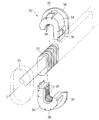
- the wire harness wiring structure unit 10 includes the wire harness WH, the exterior member 20, the attachment member 30, the accommodation unit 40, and the guide unit 50.
- the exterior member 20 is exteriorized in the part including the part spanned between the vehicle body 2 and the door 6 among the wire harness WH (refer FIG. 4).
- the exterior member 20 is a member that protects the wire harness WH from the outside and supports the wire harness WH while suppressing drooping between the vehicle body 2 and the door 6.
- the exterior member 20 is formed in a cylindrical shape, and protects the wire harness WH disposed inside. More specifically, the exterior member 20 has flexibility (entirely in the longitudinal direction) so as to bend between the vehicle body 2 and the door 6 corresponding to the opening / closing operation of the door 6, and at least the wire harness. A member having rigidity higher than WH, preferably high enough to support the wire harness WH while suppressing bending and sagging between the vehicle body 2 and the door 6 is employed.
- the exterior member 20 is a corrugated tube manufactured by extrusion molding and blow molding or vacuum molding of a synthetic resin (for example, PP (polypropylene), PA (polyamide), PE (polyethylene)).
- the corrugated tube is a member in which convex ridges and concave valleys along the circumferential direction are alternately continued in the axial direction. And in the cross-sectional view parallel to the axial direction of the corrugated tube, the inner angle between the top of the peak and the side walls on both sides and the inner angle between the bottom of the valley and the side walls on both sides change in size. It expands and contracts. That is, when a force is applied in the bending direction, the corrugated tube is deformed and bent so that each inner angle of the inner peripheral portion becomes smaller and each inner angle of the outer peripheral portion becomes larger.
- the exterior member 20 is formed in a flat shape (for example, a flat shape such as a substantially elliptical shape or a substantially rectangular shape in cross section).
- a flat shape for example, a flat shape such as a substantially elliptical shape or a substantially rectangular shape in cross section.
- it is formed in a substantially rectangular shape in section view with rounded corners. That is, it is a shape that is difficult to bend in the longitudinal direction (high rigidity) in a cross-sectional view, and is easy to bend in the short direction (high flexibility). More specifically, since the corrugated tube can be expanded and contracted in the axial direction normally at any part in the circumferential direction, the longer the distance between the inner peripheral side end part and the outer peripheral side end part, the smaller the angle change amount and the more difficult it is to bend.
- the wire harness WH may be formed in a circular shape in cross section, or may be formed in a cross sectional shape corresponding to the internal shape of the exterior member 20.
- the exterior member 20 should just have rigidity higher than the wire harness WH, and is not limited to the corrugated tube as mentioned above.
- a flat cylindrical member molded with rubber having relatively high hardness EPDM (ethylene propylene diene rubber), elastomer or the like) can be employed.
- One end of the exterior member 20 is fixed to a portion of the wire harness WH that is routed in the vehicle body 2 by being wound with a tape T or the like and fixed to an attachment member 30 that is attached to the vehicle body 2. (See FIG. 3). Moreover, the other end part of the exterior member 20 is fixed to the wire harness WH by tape T winding or the like, and is movable in the door 6 together with the wire harness WH (see FIGS. 1 and 2).
- the attachment member 30 is a member that attaches one end of the exterior member 20 that is sheathed to the wire harness WH to the vehicle body 2 so as to route the wire harness WH to the vehicle body 2 side (FIGS. 1, 3, and 4). reference).
- the attachment member 30 is fixed to one end side portion of the exterior member 20 and is formed to be attachable to the vehicle body 2. More specifically, the attachment member 30 is configured to be attachable by being pressed against a hole 2 h formed in the vehicle body 2.
- the attachment member 30 includes an insertion portion 34, a pressing portion 36, and a vehicle body side fitting portion 38.
- the insertion portion 34 is formed in a cylindrical shape that can be inserted into the hole 2h of the vehicle body 2 and in which the exterior member 20 can be disposed inside.
- the insertion part 34 is inserted toward the front of the vehicle body 2 (hereinafter, the insertion direction S) with respect to the hole 2h.
- a locking portion 35 that can be locked to the hole 2 h in a state where the insertion portion 34 is inserted into the hole 2 h is provided at the distal end portion of the insertion portion 34.
- the locking portions 35 are formed so as to protrude from the circumferential positions of the insertion portion 34 in the circumferential direction (four locations at equal intervals) to the outer peripheral side, and are respectively forward in the insertion direction S with respect to the peripheral portion of the hole 2h.
- the locking portion 35 has a locking surface that can be contacted from the side. More specifically, the locking portion 35 is formed so that the protruding dimension gradually increases from the distal end side to the proximal end side of the insertion portion 34.
- the insertion portion 34 or the locking portion 35 itself is elastically deformed toward the inner peripheral side of the insertion portion 34, and gets over the hole 2h. It is elastically returned to the outer peripheral side at the position and is locked to the peripheral edge of the hole 2h.
- the pressing portion 36 is provided continuously to the proximal end portion of the insertion portion 34, and is formed in a hook shape projecting to the outer peripheral side.
- the pressing portion 36 can come into surface contact with the peripheral portion of the hole 2h from the rear side in the insertion direction S. That is, the outer peripheral shape of the pressing portion 36 is formed larger than the hole portion 2h.
- the locking part 35 is locked from the front side in the insertion direction S with respect to the peripheral part of the hole 2h, and the presser part 36 is the peripheral part of the hole 2h. Is in surface contact from the rear side in the insertion direction S.
- the peripheral edge of the hole 2 h is sandwiched between the locking portion 35 and the pressing portion 36, and the attachment member 30 is fixed to the vehicle body 2.
- the vehicle body side fitting portion 38 is a portion that is positioned so as not to be relatively movable in the extending direction with respect to the exterior member 20 disposed in the insertion portion 34 (and the pressing portion 36).
- the vehicle body side fitting portion 38 is formed so as to be able to be fitted to the concave and convex external shape of the corrugated tube as the exterior member 20. More specifically, the vehicle body side fitting portion 38 is formed in a protruding line along the circumferential direction protruding from the inner peripheral portion of the insertion portion 34 (and the pressing portion 36) toward the inner peripheral side, and in the insertion direction S. A plurality of gaps are provided at intervals corresponding to the recesses of the exterior member 20.
- the mounting member 30 is configured by combining a pair of substantially U-shaped members (here, U-shaped members having different lengths of opposing pieces).
- a pair of substantially U-shaped members here, U-shaped members having different lengths of opposing pieces.
- an unevenness that can be fitted to each butted portion of the pair of substantially U-shaped members is formed, and the pair of substantially U-shaped members are united by engaging the unevenness. That is, by sandwiching the exterior member 20 by a pair of substantially U-shaped members, the vehicle body side fitting portion 38 is fitted to the outer peripheral portion of the exterior member 20, and the mounting member 30 extends to the exterior member 20. It is attached so that it cannot move relative to the direction.
- the attachment member 30 has a shape in which a pair of substantially U-shaped members are engaged so as not to be separated in a combined state, the mounting member 30 is combined with the hole 2h. May be maintained.
- the attachment member 30 may be connected at one end by a hinge so that a pair of substantially U-shaped members can be opened and closed.
- the attachment member 30 is attached with respect to the vehicle body 2 with the attitude
- the mounting member 30 is not limited to the above shape.
- the vehicle body side fitting portion may be formed in a flat and elongated rectangular shape that protrudes rearward from the proximal end portion of the presser portion 36 in the insertion direction S. That is, the exterior member 20 disposed in the insertion portion 34 (and the presser portion 36) is fixed to the attachment member 30 by fixing the exterior member 20 to the vehicle body side fitting portion by tape winding or tie band fastening. On the other hand, it can be positioned in the insertion direction S.
- the tie band refers to a member that can adjust and maintain the circumferential dimension of the annular body in stages.
- the attachment member may be integrally formed by injection molding as a whole.
- the attachment member 30 is not limited to the resin molded product as described above, and may be an elastomer such as rubber (for example, synthetic rubber such as EPDM) as long as it can be attached to the vehicle body 2 and the exterior member 20 can be fixed. It may be a molded grommet.
- rubber for example, synthetic rubber such as EPDM
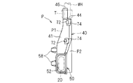
- the housing part 40 and the guide part 50 are parts constituting the protector P (see FIGS. 5 to 7).
- the accommodating part 40 is a part formed so that the wire harness WH extended from the other end part of the exterior member 20 can be accommodated so that the extra length can be absorbed.
- the guide part 50 is a part formed in the cylinder shape or groove
- the guide portion 50 has a guide port 52 into which the other end portion of the exterior member 20 can be inserted at one end portion, and the other end portion is continuous with one end portion of the housing portion 40.
- the accommodating part 40 is continuous with the other end part of the guide part 50 in one end part, and accommodates the wire harness WH extended from the other end part of the exterior member 20 inserted in the guide part 50 so that a surplus length can be absorbed. It has a possible accommodation space.
- the accommodating portion 40 has an outlet 44 through which the wire harness WH inserted in the accommodating space through the guide portion 50 can be pulled out into the door 6 (in the space between the door inner panel 7 and the trim 8). have.
- the protector P guides the exterior member 20 inserted into the guide portion 50 through the guide port 52 toward the housing portion 40, and the wire harness WH extended from the other end of the exterior member 20 is guided to the housing portion. It is a member that is accommodated in the accommodating space 40 so as to be able to absorb the extra length and extends outwardly, that is, into the door 6 through the outlet 44.
- the protector P is opened in the direction in which the guide port 52 and the outlet 44 are substantially orthogonal, and is formed in a substantially L shape in side view as a whole.
- the side surface of the protector P (wire harness wiring structure portion 10) is a surface parallel to the opening direction of the guide port 52 (guide direction of the guide portion 50) and the opening direction of the outlet 44.
- the protector P when the protector P is attached to the door 6, the front is viewed from the front of the door 6 and the side is viewed from the vehicle interior side.
- the protector P will be described in more detail by focusing on the configurations of the guide unit 50 and the storage unit 40.
- the guide portion 50 is formed in a cylindrical shape (here, a cylindrical shape having a substantially rectangular cross-sectional view) having an internal space larger than the exterior member 20 so that the exterior member 20 can be moved forward and backward. (See FIGS. 5 and 7). But the guide part 50 should just be able to insert and guide the exterior member 20, and may be formed in cylindrical shapes, such as cross-sectional view substantially elliptical shape, circular shape, or polygons other than a rectangle.
- the exterior member 20 is such that at least a part on the other end side is inserted into the guide portion 50 when the door 6 is open with the one end side portion fixed to the attachment member 30 attached to the vehicle body 2. Long extended dimensions are set.
- the guide unit 50 only needs to be able to regulate the position of the other end portion of the exterior member 20 that is advanced and retracted in the door 6 when the door 6 is opened and closed. In the closed state, the extension dimension is set such that the other end portion of the exterior member 20 protrudes into the housing portion 40. But the guide part 50 is longer than the said dimension, and may be set so that accommodation to the other end part of the exterior member 20 in the closed state of the door 6 is possible.
- the guide portion 50 may be formed such that a guide port 52 formed at one end thereof is expanded to the outer peripheral side (see FIGS. 5 to 7).
- the guide portion 50 adopts a shape that expands in all directions substantially orthogonal to the extending direction.
- the guide port 52 is formed so as to gradually expand toward one end.
- the accommodating portion 40 includes a wire harness WH extending from the other end portion of the exterior member 20 between the first route R1 and the second route R2 swelled so that the intermediate portion is separated from the first route R1. It is formed so as to be bent so as to be able to absorb the extra length (see FIG. 5).
- the accommodating portion 40 has a first wall portion 41 and a second wall portion 42 that are opposed to each other with the accommodating space in a side view.
- the wire harness WH accommodated in the accommodation space is disposed close to the first wall portion 41 when passing through the first route R1 and close to the second wall portion 42 when passing through the second route R2. .
- Each of the first wall portion 41 and the second wall portion 42 is continuous with the other end portion of the guide portion 50, and each other end portion forms a wall portion facing the outlet 44. More specifically, the first wall portion 41 extends so as to connect the other end portion of the guide portion 50 and the outlet 44 of the housing portion 40 on the inner peripheral side of the protector P having a substantially L shape in side view. is doing.
- the second wall portion 42 is spaced from the first wall portion 41 so that the wire harness WH can be bent and deformed, and is on the outer peripheral side of the substantially L-shaped protector P in side view, and the other end of the guide portion 50. It extends so as to connect the section and the outlet 44.
- the accommodating part 40 has the positioning part 46 in the door which can fix the wire harness WH at the outlet 44.
- the in-door positioning portion 46 is formed in a shape in which the opening edge of the outlet 44 partially extends (see FIGS. 5 to 7). Then, the wire harness WH drawn through the outlet 44 is in contact with the inside of the in-door positioning portion 46 and is fastened together with a tape T or tie band and fixed (here, tape T is wound). It is possible to position in the door 6 by fixing. Thereby, even if the wire harness WH on the vehicle body 2 side advances or retreats in the housing portion 40 during the opening / closing operation of the door 6, it is possible to prevent the wire harness WH routed in the door 6 from being pulled or loosened. it can.
- the configuration for fixing the wire harness WH to the accommodating portion 40 is not limited to the positioning portion 46 in the door.
- a plurality of hole portions for inserting tie bands may be formed in the door positioning portion extending in a wall shape from the outlet 44, and the wire harness WH may be fastened and fixed by inserting the tie band into the hole portion.
- the wire harness WH extended from the other end portion of the exterior member 20 is pushed into the accommodation space of the accommodation portion 40 as the door 6 is closed.
- the wire harness WH is changed from the first route R1 to the second route R2, but may be subjected to a heavy load depending on the form of the second route R2 when absorbing the extra length, such as being bent by a U-turn.
- the accommodating part 40 of this wire harness wiring structure part 10 is formed so that surplus length can be absorbed by the path
- the accommodating portion 40 has a wire harness WH larger than a path passing through a line along the guide direction (extending direction) of the guide portion 50 and a line perpendicular to the guide direction through the door positioning portion 46.
- the second wall portion 42 is formed so as to be able to restrict bending.
- the route passing through the line means that a part of the wire harness WH housed in the housing part 40 overlaps the line in the extending direction in a side view.
- the central axis of the wire harness WH does not necessarily have to pass on the line.
- the term “bent greatly” means that the wire is bent beyond the above-mentioned lines.
- the accommodating portion 40 is configured so that the wire harness WH extends in a line extending along the guide direction of the guide portion 50 and a portion of the wire harness WH that is fixed to the in-door positioning portion 46. It is preferable that the second wall portion 42 be formed so as to be able to regulate the path so as to bend into a path passing along the line along which the extra length is absorbed.
- the shape of the accommodating portion 40 is such that the wire harness WH passing through the second path R2 is bent before or on the line along the extending direction of the portion fixed to the in-door positioning portion 46. Shape.
- the accommodating portion 40 is configured to absorb the excess length by bending the wire harness WH into a path passing through a line along the guide direction of the guide portion 50 and a line orthogonal to the guide direction.
- the wall part 42 is formed so that path regulation is possible.
- the accommodating portion 40 is configured such that, in the opened state of the door 6, an intermediate portion between the other end portion of the exterior member 20 and the in-door positioning portion 46 is connected to the other end portion of the exterior member 20.
- the 1st wall part 41 is formed so that a path
- the second wall portion 42 includes a guide portion side wall portion 42a that is continuous with the other end portion of the guide portion 50, an outlet side wall portion 42b that forms one wall portion of the outlet 44, a guide portion side wall portion 42a, and an outlet side wall.
- the door positioning portion 46 described above is formed in an L shape in plan view with a portion extending from the other end portion of the outlet side wall portion 42b of the second wall portion 42 as one piece. That is, a portion of the wire harness WH that is fixed to the door positioning portion 46 extends along the extending direction in a state of being in contact with the outlet side wall portion 42b.
- the outlet 44 is formed so as to open in a direction substantially orthogonal to the guide port 52, and the fixing portion of the wire harness WH is guided by the guide 50 together with the door positioning portion 46 in a side view. It extends along a direction substantially orthogonal to the direction.
- the guide part side wall part 42a is a wall part extending linearly along the guide direction from the other end of the guide part 50 in a side view.
- the outlet side wall part 42b is a wall part extending along a direction substantially orthogonal to the guide part side wall part 42a in a side view.
- the outlet side wall part 42 b forms one wall part of the outlet 44 on the proximal end side of the door positioning part 46.
- the curved portion 42c is set in a gentle curved shape in a side view, and connects the other end portion of the guide portion side wall portion 42a and one end portion of the outlet side wall portion 42b.
- the wire harness WH is curved at a portion along the curved portion 42c in a form passing through the second route R2 along the second wall portion 42, and both side portions thereof are the guide portion side wall portion 42a and the outlet side wall. It is accommodated along a line substantially orthogonal along the portion 24b.
- the part accommodated along the bending part 42c among the wire harnesses WH is located inside the said substantially orthogonal line. Accordingly, the wire harness WH that absorbs the extra length is restricted from being bent beyond the position of the in-door positioning portion 46 in a direction away from the guide portion 50 (the rear side of the door 6 to be attached).
- the first wall portion 41 has a linear portion extending in a direction connecting the other end portion of the exterior member 20 and the in-door positioning portion 46 when the door 6 is open in a side view. Moreover, the edge part by the side of the guide part 50 among the 1st wall parts 41 continues in a gentle curve shape with respect to the other end part of the guide part 50, and the edge part by the side of the outlet 44 is formed in linear form. In addition, it is formed in a gently curved shape so as to connect the linear portions.
- the first wall 41 is closer to a line connecting the other end of the exterior member 20 and the in-door positioning portion 46 in the opened state of the door 6, that is, the wire harness WH is a first route R1 that is the shortest route. It is good to be provided at a position where wiring is possible. Thereby, the path
- the first wall 41 is second from the line connecting the other end of the exterior member 20 and the outlet 44 when the door 6 is open. It may be provided on the wall 42a side.
- the wire harness WH is fixed to the other end portion of the exterior member 20 and the door positioning portion 46 with a tape T, and when the door 6 is in an open state, a portion adjacent to both the fixing portions is its own. It is gently curved by the rigidity, and an intermediate portion between the two fixed portions extends substantially linearly (first path R1).
- first path R1 the linear portion of the wire harness WH passing through the first path R ⁇ b> 1 extends in parallel to the direction connecting the other end portion of the exterior member 20 and the in-door positioning portion 46 in the opened state of the door 6.
- the 1st wall part 41 is formed so that the linear intermediate part may extend along the linear part of the wire harness WH which passes 1st path
- the protector P is disposed in a recess 7 h formed in the door inner panel 7. More specifically, the protector P is formed to be able to be arranged in one direction with respect to the recess 7h (here, from the vehicle interior side toward the vehicle exterior side through the vehicle interior side opening of the recess 7h). .
- the guide portion 50 extends along the front-rear direction of the door 6, the guide portion 50 is positioned on the front side with respect to the housing portion 40, and the outlet 44 faces the upper side of the door 6. (See FIGS. 1 and 2). Further, the attachment position of the protector P will be described in relation to the manner of attachment of the attachment member 30 to the vehicle body 2.
- the attachment member 30 and the protector P are arranged such that the exterior member 20 is bridged below the opening degree restricting portion 3. These are formed so that they can be attached to the vehicle body 2 or disposed in the door 6.
- the protector P can be disposed in the door 6 such that the guide port 52 of the guide portion 50 is positioned below the door side connecting portion of the opening degree restricting portion 3.
- the concave portion 7h is formed in a concave shape having an accommodation space in which the protector P can be accommodated entirely or partially in the posture and the position. And the guide port 52 of the guide part 50 is exposed outside the door 6 through the opening part ahead of the door 6 among the recessed parts 7h.
- the protector P is formed so as to be attachable to the attachment posture and position by being pressed toward the outer side of the passenger compartment against the door inner panel 7 of the door 6.
- the protector P has the fixing
- the fixing portion 58 a base shaft portion that protrudes from the outer surface of the protector P (here, a first member P1 to be described later), and a spring portion that extends from the distal end portion to the outer peripheral side and elastic toward the inner peripheral side.
- a configuration having a deformable locking portion can be employed.
- the protector P may be fixed to the door inner panel 7 by screwing or the like. Even in this case, the protector P may be disposed from the vehicle interior side toward the vehicle exterior side with respect to the door inner panel 7 (recess 7h).
- the exterior member 20 spanned between the attachment member 30 and the guide part 50 (guide opening
- the exterior member 20 is partially fixed to the vehicle body 2 via the attachment member 30, slack between the attachment member 30 and the guide portion 50 is suppressed by its own rigidity, and the other end The side portion is advanced and retracted into the guide portion 50 more smoothly and reliably.
- the protector P is formed in a substantially L shape as a whole. For this reason, a space surrounded by the protector P is created on the inner side of the protector P, that is, above the guide portion 50 and in front of the housing portion 40 in the state of being disposed on the door 6.
- the protector P is positioned with respect to the recess 7 h in such a posture that the guide port 52 of the guide portion 50 is located below the fixed position of the case portion of the opening degree restricting portion 3 and the outlet 44 faces upward of the vehicle body 2.
- the protector P is disposed on the door 6 so as to surround the opening restriction portion 3 from two directions, and the arm portion of the opening restriction portion 3 advances and retreats in a space surrounded by the protector P. Thereby, the space in the door 6 in which several electric equipment is installed can be used effectively.
- the above-described protector P is configured by combining the first member P1 and the second member P2 (see FIGS. 6 and 7).
- a combination of a concave member and a lid member is employed as the first member P1 and the second member P2.
- the protector P can be obtained by casting the first member P1 and the second member P2 by pouring molten resin materials into a mold, and combining them.
- the first member P1 and the second member P2 may be formed so as to be able to maintain a combined state.
- a plurality of locking portions 72 or locked portions 74 are formed on the first member P1 and the second member P2, respectively, and each locking portion 72 is brought close to the first member P1 and the second member P2.
- the to-be-latched part 74 is good to be comprised so that it may latch (refer FIG. 6, FIG. 7).
- a wall-like locked part 74 provided at an interval on the outer surface of the protector P, and an insertion that can be inserted between the outer surface and the locked part 74
- a combination of a locking portion 72 having a piece and a protruding portion protruding outward from the distal end portion of the insertion piece can be employed. That is, when the insertion piece of the locking portion 72 is inserted between the outer surface of the protector P and the locked portion 74, the protruding portion of the locking portion 72 comes into contact with the edge of the locked portion 74. And is configured to be locked.
- the protector P is formed such that the guide port 52 and the outlet 44 are in a positional relationship shifted in the mounting direction with respect to the door 6 (see FIGS. 3 and 6).
- the wire harness WH bent in the accommodating part 40 receives the force around a central axis, and is deform
- the wire harness routing structure 10 may be assembled before the vehicle is assembled by modularizing the wire harness WH, the exterior member 20, the mounting member 30, and the protector P that are routed from the vehicle body 2 into the door 6. That is, the wire harness WH is disposed in the exterior member 20, the attachment member 30 is attached to one end portion of the exterior member 20, and the one end thereof is fixed by winding the tape T around the wire harness WH, and The other end of the exterior member 20 is wound around the wire harness WH with a tape T and fixed. And the other end side part of the exterior member 20 is arrange
- the other end portion of the exterior member 20 is positioned on one end side of the guide portion 50 compared to the closed state, and the wire harness WH extending from the other end portion of the exterior member 20 is: It is accommodated in the accommodation space through the first route R1. That is, the wire harness WH partially extends linearly along the straight portion of the first wall portion 41, and both side portions of the wire harness WH gradually move toward the other end portion of the exterior member 20 and the in-door positioning portion 46. It extends in a curved shape.
- the exterior member 20 moves forward into the guide portion 50, and the wire harness WH extended from the other end is pushed into the housing space and the second wall portion. 42a approaches.
- the wire harness WH is restricted from bending toward the rear side of the door 6 from the portion fixed to the door positioning portion 46 by the outlet side wall portion 42b.
- the wire harness WH is restricted from being bent in a direction away from the outlet 44 by the guide side wall 42a.
- the wire harness WH will be in the state accommodated in accommodation space through 2nd path
- the part accommodated in accommodation space among the wire harnesses WH becomes long, and extra length is absorbed.
- the surplus length absorption operation in which the wire harness WH is changed from the first route R1 to the second route R2, a bending operation in which the wire harness WH is U-turned is suppressed, and a load applied to the wire harness WH is reduced as much as possible. is doing.
- the extra length absorbing operation is set so that the wire harness WH is maintained in a bent state such that the both side portions of the bent portion intersect with each other at an angle of 90 degrees or more depending on the shape of the accommodating portion 40. Has been.
- the example has been described in which the outlet side wall part 42b of the second wall part 42 is formed in a straight line along the direction substantially orthogonal to the guide part side wall part 42a, but the shape of the accommodating part 40 is It is not limited.
- the accommodating part may be formed in a shape in which a portion of the outlet side wall part facing the guide part 50 swells in a direction away from the guide part 50 (the rear side of the door 6).
- the swelled portion of the outlet side wall portion is referred to as an inflating portion 148.
- FIG. 8 shows a protector Pa in which the outlet side wall portion 142 b of the second wall portion 142 of the accommodating portion 140 has an inflating portion 148.
- the protector Pa the only part different from the protector P is the expansion part 148, and the other parts are denoted by the same reference numerals as those of the protector P, and the description thereof is omitted.
- the inflatable portion 148 may be set so as to protrude smaller than the diameter of the wire harness WH with respect to the other portion (the portion that forms the outlet 44) of the outlet side wall 142b. That is, the portion of the wire harness WH passing through the second path R2 that is disposed along the outlet side wall 142b is along the extending direction of the portion that is fixed to the door positioning portion 46 in a side view. It passes on one line (the one-dot chain line in the vertical direction in FIG. 8).
- the extending direction of the in-door positioning portion 46 is not limited to the direction orthogonal to the guiding direction of the guiding portion 50, and may be inclined with respect to the guiding direction.
- the outlet side wall portion 42b may be formed so as to extend along the extending direction of the in-door positioning portion 46 and to be inclined with respect to the guide side wall portion 42a.
- the above-described inflating portion may be formed.
- the exterior member 20 does not need to be fixed to the wire harness WH from which the other end extends.
- the corrugated tube as the exterior member 20 is provided with a wire harness WH inside, a split (slit) may be formed in its extending direction, but the split opening is suppressed.
- the other end may be wound with a tape T.
- the wire harness WH may be fixed to the in-door positioning portion 46 with a tie band 92.
- the door positioning portion 46 may be formed with a hole through which the tie band 92 is passed.
- a tape T may be wound around a portion of the wire harness WH that is tightened by the tie band 92 as a measure against disconnection. That is, the tape T may be wound around the outer periphery of the wire bundle constituting the wire harness WH, and the tie band 92 may be tightened from above to fix the wire harness WH to the in-door positioning portion 46.
- the structure which winds the tape T around the wire harness WH as a countermeasure against disconnection can also be employed when the wire harness WH is fixed to the in-door positioning portion 46 by tape T winding.
- the attachment member 30 a member having a lock structure part capable of maintaining the combined state of a pair of U-shaped members as shown in FIG. 10 may be adopted.
- the attachment member 30 is formed at one end of each of the butted portions of the pair of U-shaped members, and at the other end, and the locking portion 37 can be locked.
- a receiving portion 39 a receiving portion 39.
- the locking portion 37 is a portion having a locking claw that protrudes from the distal end portion of the insertion portion that protrudes from one end portion of the U-shaped member toward the inner peripheral side of the U-shaped member.
- This locking claw is formed in a substantially triangular shape in a sectional view in which the protruding dimension gradually increases from the distal end side toward the proximal end side, and has a locking surface facing the proximal end side.
- the receiving part 39 is formed in the concave shape opened in the other end surface of a U-shaped member, and has the hole which can arrange
- the accommodating portion 40 and the guide portion 50 are not limited to being formed as a single-part protector P, and may be configured as separate parts.
- the accommodating part 40 and the guide part 50 are good to be arrange
- attachment member 30 and the protector P are not limited to the case where the exterior member 20 is formed so as to be attachable to a position located below the opening degree restriction unit 3, for example, above or side of the opening degree restriction unit 3. It may be attachable so that it is located in.
- the wire harness wiring structure portion 10 is applied between the vehicle body 2 and the door 6 as the front side door.
- the wire harness WH is bridged between the center pillar (the pillar between the front side door and the rear side door) and the rear side door. That is, a hole is formed in the center pillar, and the attachment member 30 is attached here.
- the guide member 50 guides the exterior member 20 that is sheathed on the wire harness WH, and the housing portion 40 extends from the other end portion of the exterior member 20. Since the harness WH is formed so as to be able to absorb the surplus length, the bending performance is improved by absorbing the surplus length by smoothly moving the wire harness WH back and forth in the door 6 as the door 6 opens and closes. be able to.
- the housing portion 40 is bent more than the path through which the wire harness WH passes through the line along the guide direction of the guide portion 50 and the in-door positioning portion 46 and the line orthogonal to the guide direction.
- the 2nd wall part 42 is formed so that control is possible. That is, the wire harness WH in the housing portion 40 is route-restricted by the second wall portion 42, and in a side view, the second route R2 at the time of absorbing the extra length passes through an orthogonal line or more gently. It becomes a bent form.
- the shape of the protector P of the wire harness routing structure 10 is effective when a relatively large force is required for bending deformation when absorbing the extra length, such as when the diameter of the wire harness WH is large.
- the accommodating part 40 was along the extending direction of the part currently fixed to the positioning part 46 in the door among the line along the guide direction of the guide part 50, and the wire harness WH in the side view.
- the second wall portion 42 is formed so as to be able to regulate the path so as to be bent into a path passing through the line and absorb the surplus length. For this reason, even when the extending direction of the portion fixed to the door positioning portion 46 of the wire harness WH is inclined with respect to the direction orthogonal to the guide direction of the guide portion 50, the load applied to the wire harness WH is further reduced. be able to.
- the accommodating portion 40 absorbs the extra length by bending the wire harness WH into a path passing through a line along the guide direction of the guide portion 50 and a line orthogonal to the guide direction of the guide portion 50. Since the 2nd wall part 42 is formed so that path
- the intermediate portion between the other end of the exterior member 20 and the door positioning portion 46 in the wire harness WH is connected to the other end of the exterior member 20. Since the first wall portion 41 is formed so as to be able to regulate the path so as to be accommodated in a path parallel to the direction connecting the in-door positioning portion 46, the load applied to the wire harness WH can be reduced in the opened state of the door 6. At the same time, the path difference between the first path R1 and the second path R2 can be increased to ensure a larger extra length absorption space.
- the first wall portion 41 of the accommodating portion 40 has a linear portion extending along a direction connecting the other end portion of the exterior member 20 and the in-door positioning portion 46 in the open state of the door.
- the wall portion 42 has a guide portion side wall portion 42a extending along the guide direction of the guide portion 50, and the portion of the wire harness WH fixed by the in-door positioning portion 46 is extended through the curved portion 42c. It is formed so as to have an outlet side wall portion 42b extending along the existing direction. For this reason, the load added to the wire harness WH at the time of opening and closing of the door 6 can be reduced, ensuring the surplus length absorption space of the wire harness WH large. Moreover, the dimension which protrudes in the back side of the door 6 from the in-door positioning part 46 among the protectors P can be made small.
- the exterior member 20 is a flat corrugated tube having higher rigidity than the wire harness WH, and is bridged between the vehicle body 2 and the door 6 in a flat posture along the vertical direction, the wire harness WH It is possible to suppress bending and sagging while enabling bending deformation in the horizontal direction in the entire portion spanned between the vehicle body 2 and the door 6. Thereby, the wire harness WH can be more reliably advanced and retracted into the guide portion 50 and the accommodating portion 40 in accordance with the opening / closing operation of the door 6, and the extra length can be absorbed smoothly.
- the mounting member 30 is fitted only by positioning the one end side portion of the exterior member 20 that is sheathed on the wire harness WH by the vehicle body side fitting portion 38 and pressing it toward the insertion direction S against the hole 2h. Therefore, the wire harness WH can be easily routed to the vehicle body 2 side.
- the exterior member 20 is formed in a flat shape and is provided in a flat posture along the vertical direction of the vehicle body 2, the exterior member 20 can be routed in a narrow space in the inside and outside of the door 6 and is disposed in the door 6.
- the guide part 50 and the accommodating part 40 to be made can also be made flat, and can be applied even in the case of the door 6 in which the space between the door inner panel 7 and the trim 8 is narrow.
- the exterior member 20 is provided in a flat posture along the vertical direction of the vehicle body 2, it is relatively difficult to bend in the vertical direction, and the hanging of the wire harness WH can be suppressed.
- the member for water-stopping such as a grommet
- omitted a reduction in a number of parts and an assembly man-hour Therefore, it is possible to reduce costs and improve work efficiency.
- the structure which does not use a grommet it can abbreviate
- the expansion work of the grommet at the time of letting the wire harness WH pass can also be omitted.
- the wire harness wiring structure part 10 since the wire harness wiring structure part 10 has wired the wire harness WH between the door inner panel 7 and the trim 8, it can save the effort which inserts and wires the wire harness WH through a through-hole. Assembling work can be performed in the exposed work space, so that assembling performance can be improved and work efficiency can be improved.
- wire harness wiring structure 10 has been described in detail, but the above description is an example in all aspects, and the present invention is not limited thereto. It is understood that countless variations that are not illustrated can be envisaged without departing from the scope of the present invention.
Landscapes
- Engineering & Computer Science (AREA)
- Architecture (AREA)
- Civil Engineering (AREA)
- Structural Engineering (AREA)
- Mechanical Engineering (AREA)
- Electric Cable Arrangement Between Relatively Moving Parts (AREA)
- Details Of Indoor Wiring (AREA)
Abstract
ワイヤーハーネス配索構造部は、ワイヤーハーネスと、ワイヤーハーネスに外装されている外装部材と、車体に取り付け可能であると共に、外装部材の一端側部分に固定されている取付部材と、外装部材の他端部から延出されるワイヤーハーネスを余長吸収可能に収容すると共に、ワイヤーハーネスをドア内に引出し可能な引出口でワイヤーハーネスを固定可能なドア内位置決め部とを有する収容部と、外装部材の他端側部分を収容部に向けて案内可能な案内部とを備えている。収容部は、側面視において、ワイヤーハーネスが、案内部の案内方向に沿ったライン及びドア内位置決め部を通って案内方向に直交するラインを通る経路より大きく曲げられることを規制可能な壁部を有する。
Description
本発明は、車体とドアとの間にワイヤーハーネスを配索する技術に関する。
特許文献1には、車体とドアとの間のワイヤーハーネスの配索構造が開示されている。このワイヤーハーネスの配索構造は、ドアに配索されて車体側へと引出されるワイヤーハーネスが硬質樹脂製のチューブ内に挿通され、当該チューブをドアに設けたガイド部分にスライド自在に収容すると共に、チューブから引出されるワイヤーハーネスの余長部をガイド部分に設けた余長吸収用空間に収容している。このガイド部分は、直線状の上辺周壁と、当該上辺周壁と直線状のスライド用空間をあけて配置し下方へと湾曲させた形状の先端側の側辺周壁と、前記側辺周壁に近接するように湾曲させた形状の他方側の側辺周壁とを有している浅底の略三角形状に形成されている。そして、スライド用空間から、一対の側辺周壁の間の下端開口であるドア内の引出用開口にかけた大容積部が余長吸収用空間である。この余長吸収用空間は、上辺周壁と側辺周壁のコーナー部に向かって大きな半径を有する湾曲状空間としている。
しかしながら、特許文献1のワイヤーハーネスの配索構造によると、ドアの閉動作に伴って、チューブから引出されているワイヤーハーネスが余長吸収用空間内に押し込まれると、当該ワイヤーハーネスは、ドア内の引出用開口を越えてドアの後方側に凸となるようにコーナー部に沿って湾曲するようにして収容される。このため、ワイヤーハーネスには、ドアの閉動作時に比較的大きな負荷が加わってしまい、スムーズな余長吸収が阻害されてしまう恐れがある。
そこで、本発明は、ドアの開閉動作におけるワイヤーハーネスの余長吸収をよりスムーズに行うことで屈曲性能を向上させることを目的とする。
第1の態様は、ワイヤーハーネスを車体とドアとの間に配索するワイヤーハーネス配索構造部であって、前記ワイヤーハーネスと、前記ワイヤーハーネスのうち前記車体と前記ドアとの間に架け渡される部分を含む部分に外装されている外装部材と、前記車体に取り付け可能であると共に、前記外装部材の一端側部分に固定されている取付部材と、前記ドア内に配設可能で、前記外装部材の他端部から延出される前記ワイヤーハーネスを余長吸収可能に収容すると共に、前記ワイヤーハーネスを前記ドア内に引出し可能な引出口で前記ワイヤーハーネスを固定可能なドア内位置決め部を有する収容部と、前記ドア内に配設可能で、前記外装部材の他端側部分を前記収容部に向けて案内可能な筒状又は溝状の案内部とを備え、前記収容部は、側面視において、前記ワイヤーハーネスが、前記案内部の案内方向に沿ったライン及び前記ドア内位置決め部を通って前記案内方向に直交するラインを通る経路より大きく曲げられることを規制可能な壁部を有する。
第2の態様は、第1の態様に係るワイヤーハーネス配索構造部であって、前記収容部は、側面視において、前記ワイヤーハーネスを、前記案内部の案内方向に沿ったライン及び前記ワイヤーハーネスのうち前記ドア内位置決め部に固定されている部分の延在方向に沿ったラインを通る経路に曲げて余長吸収するように、前記壁部が経路規制可能に形成されている。
第3の態様は、第1又は第2の態様に係るワイヤーハーネス配索構造部であって、前記収容部は、側面視において、前記ワイヤーハーネスを、前記案内部の案内方向に沿ったライン及び前記案内部の案内方向に直交するラインを通る経路に曲げて余長吸収するように、前記壁部が経路規制可能に形成されている。
第4の態様は、第1~第3のいずれか一態様に係るワイヤーハーネス配索構造部であって、前記収容部は、側面視において、前記ドアの開状態において、前記ワイヤーハーネスのうち前記外装部材の他端部と前記ドア内位置決め部との中間部分を、前記外装部材の他端部と前記ドア内位置決め部とを結ぶ方向に平行な経路で収容するように、前記壁部が経路規制可能に形成されている。
第5の態様は、第1~第4のいずれか一態様に係るワイヤーハーネス配索構造部であって、前記収容部は、側面視において収容空間を挟んで対向する第1壁部と第2壁部とを有し、前記第1壁部は、側面視において、前記ドアの開状態における前記案内部の他端部と前記ドア内位置決め部とを結ぶ方向に沿って延在する直線状の部分を有し、前記第2壁部は、側面視において、前記案内部の案内方向に沿って延在すると共に、湾曲部を介して、前記ワイヤーハーネスのうち前記ドア内位置決め部で固定されている部分の延在方向に沿って延在する。
第6の態様は、第1~第5のいずれか一態様に係るワイヤーハーネス配索構造部であって、前記外装部材は、前記ワイヤーハーネスより高い剛性を有する扁平なコルゲートチューブであり、上下方向に沿って扁平な姿勢で前記車体と前記ドアとの間に架け渡される。
第1の態様に係るワイヤーハーネス配索構造部によると、案内部によりワイヤーハーネスに外装された外装部材を案内すると共に、収容部により当該外装部材の他端部から延出されるワイヤーハーネスを余長吸収可能に収容するように形成されているため、ワイヤーハーネスをドアの開閉動作に伴ってドア内にスムーズに進退させて余長吸収することができる。しかも、収容部は、側面視において、ワイヤーハーネスが、案内部の案内方向に沿ったライン及びドア内位置決め部を通って案内方向に直交するラインを通る経路より大きく曲げられることを規制可能な壁部を有するため、ワイヤーハーネスに加わる負荷をなるべく小さくして、ドアの開閉動作におけるワイヤーハーネスの余長吸収をよりスムーズに行い屈曲性能向上が可能となる。
第2の態様に係るワイヤーハーネス配索構造部によると、収容部が、側面視において、ワイヤーハーネスを、案内部の案内方向に沿ったライン及びワイヤーハーネスのうちドア内位置決め部に固定されている部分の延在方向に沿ったラインを通る経路に曲げて余長吸収するように、壁部が経路規制可能に形成されているため、ワイヤーハーネスに加わる負荷をより小さくすることができる。
第3の態様に係るワイヤーハーネス配索構造部によると、収容部が、側面視において、ワイヤーハーネスを、案内部の案内方向に沿ったライン及び案内部の案内方向に直交するラインを通る経路に曲げて余長吸収するように、壁部が経路規制可能に形成されているため、ワイヤーハーネスに加わる負荷をより小さくしつつ、より大きく余長吸収することができる。
第4の態様に係るワイヤーハーネス配索構造部によると、収容部が、側面視において、ドアの開状態において、ワイヤーハーネスのうち外装部材の他端部とドア内位置決め部との中間部分を、外装部材の他端部とドア内位置決め部とを結ぶ方向に平行な経路で収容するように、壁部が経路規制可能に形成されているため、ドアの開状態においてワイヤーハーネスに加わる負荷を小さくできると共に、余長吸収スペースをより大きく確保することができる。
第5の態様に係るワイヤーハーネス配索構造部によると、収容部は、側面視において、第1壁部がドアの開状態における外装部材の他端部とドア内位置決め部とを結ぶ方向に沿って延在する直線状の部分を有し、第2壁部が案内部の案内方向に沿って延在すると共に、湾曲部を介して、ワイヤーハーネスのうちドア内位置決め部で固定されている部分の延在方向に沿って延在するように形成されている。このため、ワイヤーハーネスの余長吸収スペースを確保しつつ、ドアの開閉時にワイヤーハーネスに加わる負荷を軽減することができる。
第6の態様に係るワイヤーハーネス配索構造部によると、外装部材が、ワイヤーハーネスより高い剛性を有する扁平なコルゲートチューブであり、上下方向に沿って扁平な姿勢で車体とドアとの間に架け渡されるため、ワイヤーハーネスのうち車体とドアとの間に架け渡される部分全体において水平方向における曲げ変形を可能にしつつ屈曲及び垂れ下がりを抑制することができる。これにより、ドアの開閉動作に伴ってワイヤーハーネスをより確実に案内部及び収容部内に進退動作させることができ、スムーズに余長吸収することができる。
以下、実施形態に係るワイヤーハーネス配索構造部10について説明する(図1、図2参照)。このワイヤーハーネス配索構造部10は、自動車の車体2とドア6との間にワイヤーハーネスWHを配索するものである。
ワイヤーハーネスWHは、ドア6に搭載されるパワーウインドウ、ドアロック、サイドミラー用モータ、スピーカー、スイッチ系統等の電気機器に対して電源供給又は信号伝達するための複数の電線が、配索経路に対応して束ねられて構成されている。ここで、ワイヤーハーネスWHのうち車体2からドア6に架け渡される部分は、上記複数の電線が1本に束ねられて構成されている。そして、ワイヤーハーネスWHは、ドア6内で分岐され上記各種電気機器に接続される。
ドア6は、車体2に形成されている出入口を開閉可能なように、車体2に対してドアヒンジ5及び開度規制部3を介して連結されている(図1、図3参照)。ここで、車体2とは、金属部材で形成されたフレーム部分を言うものとする。ここでは、対象とするドア6は、フロントサイドドアであり、説明の便宜上、垂直方向に沿った軸(ドアヒンジ5の回転軸)周りに姿勢変更するように車体2に連結されているものとする。以下、ドア6について、開閉姿勢に関わらず、閉姿勢における前後方向をドア6の前後方向として説明する。
上記開度規制部3(ドアチェックリンクとも言う)は、ドア6を所定の開度で維持するための部材であり、アーム部とケース部とを備えている。アーム部は、長手方向複数位置に他の部分より肉薄な部分が形成された棒状に形成されている。ケース部は、アーム部を挟むように押圧付勢される挟持部を内部に有する筐状に形成されている。そして、ドア6の半開姿勢及び全開姿勢等の姿勢で、挟持部がアーム部の薄肉部を挟んで、ドア6の姿勢を維持する。
また、ドア6には、その周縁部に沿って防水用のウェザーストリップ6wが設けられている(図3参照)。このウェザーストリップ6wは、ドア6を閉めた状態で、車体2の開口縁部に密着して車室内外において水密状態を保持できるゴム等で形成された部材である。なお、図3ではドア6に設けられたウェザーストリップ6wのみを示しているが、車体2の出入口の開口縁部にもウェザーストリップが設けられていてもよい。すなわち、このようなウェザーストリップは、ドア6の周縁部に密着可能であるとよい。
ドア6は、金属材料で形成されたドアインナーパネル7及びその車室外側に設けられる外装部材としてのドアアウターパネルと、樹脂材料等で形成され、ドアインナーパネル7の車室内側に取り付けられる内装部材としてのトリム8とを有している(図3参照)。また、ドア6は、その前端部から内部にワイヤーハーネスWHを挿通可能に構成されている。ここでは、ドアインナーパネル7の前方側部分に、前端部で開口する凹部7hが形成され、この凹部7hを通じて車体2側からドアインナーパネル7とトリム8との間にワイヤーハーネスWHを配索するようになっている。なお、この凹部7hは、後述するプロテクタPを収容可能に形成されている。
また、車体2には、ドア6により開閉される出入口の開口縁部のうち、ドア6の閉姿勢で凹部7hの前方側開口部と対向する部分に、車体2内にワイヤーハーネスWHを配索するための孔部2hが形成されている(図1参照)。ここでは、凹部7hと孔部2hとは、車体2の前後方向において対向するように形成されている。なお、凹部7h及び孔部2hは、ドア6を閉めた状態では、車体2及びドア6により隠れるようになっている(図2参照)。
また、ここでは、ワイヤーハーネスWHは、車体2とドア6との間でウェザーストリップ6wより車室内側に配索されるため、凹部7hの前方側開口及び孔部2hは、当該ウェザーストリップ6wより車室内側に形成されている(図2参照)。ウェザーストリップがドア6の内外方向に複数設けられている場合、上記ウェザーストリップ6wとは、最も車室外側に配設されるウェザーストリップをいい、ワイヤーハーネスWHもこのウェザーストリップ6wより車室内側に配索されればよい。すなわち、車体2とドア6との間に配索されるワイヤーハーネスWHより車室内側に別のウェザーストリップが設けられていてもよい。
ワイヤーハーネス配索構造部10は、上記ワイヤーハーネスWHと、外装部材20と、取付部材30と、収容部40と、案内部50とを備えている。
ワイヤーハーネスWHのうち車体2とドア6との間に架け渡される部分を含む部分には、外装部材20が外装されている(図4参照)。この外装部材20は、ワイヤーハーネスWHを、外部から保護すると共に、車体2とドア6との間で垂れ下がり等を抑制して支持する部材である。
外装部材20は、筒状に形成され、ワイヤーハーネスWHを内部に配設した状態で保護する。より具体的には、外装部材20には、ドア6の開閉動作に対応して車体2とドア6との間で曲がるように可撓性を(長手方向全体的に)有すると共に、少なくともワイヤーハーネスWHより高い剛性、好ましくは、車体2とドア6との間における屈曲及び垂れ下がりを抑制してワイヤーハーネスWHを支持可能な程度に高い剛性を有する部材が採用される。ここでは、外装部材20は、合成樹脂(例えば、PP(ポリプロピレン)、PA(ポリアミド)、PE(ポリエチレン))を、押出成型すると共にブロー成型或いはバキューム成型して製造されたコルゲートチューブである。コルゲートチューブは、周方向に沿った凸条の山部及び凹条の谷部が軸方向に交互に連続した部材である。そして、コルゲートチューブは、軸方向に平行な断面視において、山部の頂部とその両側の側壁部との内角、及び、谷部の底部とその両側の側壁部との内角が大小変化することにより伸縮する。つまり、コルゲートチューブは、曲げ方向に力が加えられると内周側の部分の各内角が小さくなるように変形すると共に、外周側の部分の各内角が大きくなるように変形して曲げられる。
また、この外装部材20は、扁平な形状(例えば、断面視略楕円形、略長方形等の扁平な形状)に形成されている。ここでは、角が丸められた断面視略長方形に形成されている。すなわち、断面視における長手方向に曲がり難く(剛性が高く)、短手方向に曲がりやすい(可撓性が高い)形状である。より具体的には、コルゲートチューブの軸方向の伸縮可能量は通常周方向どの部分でも変わらないため、内周側端部と外周側端部との距離が長いほど角度変化量が小さく曲がり難い。なお、ワイヤーハーネスWHは、断面視円形に形成されていても、外装部材20の内部形状に対応した断面形状に形成されていてもよい。
なお、外装部材20は、ワイヤーハーネスWHより高い剛性を有していればよく、上述したようなコルゲートチューブに限定されるものではない。例えば、外装部材として、比較的硬度が高いゴム(EPDM(エチレンプロピレンジエンゴム)、エラストマー等)により成形性された扁平な筒状の部材を採用することができる。
上記外装部材20の一端部は、ワイヤーハーネスWHのうち車体2内に配索される部分に対してテープT巻き等されて固定されると共に、車体2に取り付けられる取付部材30に対して固定されている(図3参照)。また、外装部材20の他端部は、ワイヤーハーネスWHに対してテープT巻き等により固定され、当該ワイヤーハーネスWHと共にドア6内で移動可能とされている(図1、図2参照)。
取付部材30は、ワイヤーハーネスWHを車体2側に配索するように、ワイヤーハーネスWHに外装されている外装部材20の一端部を車体2に取り付ける部材である(図1、図3、図4参照)。この取付部材30は、外装部材20の一端側部分に固定され、車体2に対して取り付け可能に形成されている。より具体的には、取付部材30は、車体2に形成されている孔部2hに対して押し付けることにより取り付け可能に構成されている。この取付部材30は、挿入部34と、押え部36と、車体側嵌合部38とを有している。
挿入部34は、車体2の孔部2h内に挿入可能、且つ、内側に外装部材20を配設可能な筒状に形成されている。ここでは、挿入部34は、孔部2hに対して車体2の前方(以下、挿入方向S)に向けて挿入される。挿入部34の先端側部分には、挿入部34を孔部2h内に挿入した状態で孔部2hに対して係止可能な係止部35が設けられている。この係止部35は、挿入部34の周方向複数位置(ここでは等間隔に4箇所)から外周側に突出するように形成され、それぞれ、孔部2hの周縁部に対して挿入方向S前方側から接触可能な係止面を有している。より具体的には、係止部35は、挿入部34の先端側から基端側に向けて徐々に突出寸法が大きくなるように形成されている。そして、各係止部35は、挿入部34が孔部2hに挿入される際に、挿入部34又は係止部35自身が挿入部34の内周側に弾性変形し、孔部2hを乗り越えた位置で外周側に弾性復帰して孔部2hの周縁部に係止するようになっている。
押え部36は、挿入部34の基端部に連続して設けられ、その外周側に張り出す鍔状に形成されている。この押え部36は、孔部2hの周縁部に対して、挿入方向S後方側から面接触可能である。すなわち、押え部36の外周形状は、孔部2hより大きく形成されている。
そして、挿入部34が孔部2hに挿入されると、係止部35が孔部2hの周縁部に対して挿入方向S前方側から係止すると共に、押え部36が孔部2hの周縁部に対して挿入方向S後方側から面接触する。これにより、孔部2hの周縁部が係止部35と押え部36とで挟まれて、取付部材30は車体2に対して固定される。
車体側嵌合部38は、挿入部34(及び押え部36)内に配設される外装部材20に対して、その延在方向に相対移動不能に位置決めする部分である。ここでは、車体側嵌合部38は、外装部材20としてのコルゲートチューブの凹凸外部形状に対して嵌合可能に形成されている。より具体的には、車体側嵌合部38は、挿入部34(及び押え部36)の内周部から、内周側に突出する周方向に沿った凸条に形成され、挿入方向Sにおいて、外装部材20の凹部に対応する間隔で複数設けられている。
上記取付部材30は、一対の略U字部材(ここでは、対向片の長さが異なるU字形状)を合体させることにより構成される。ここでは、一対の略U字部材の各突き合わせ部分に嵌合可能な凹凸が形成され、凹凸嵌合することにより一対の略U字部材が合体される。すなわち、一対の略U字部材により外装部材20を挟み込むことにより、車体側嵌合部38が外装部材20の外周部に対して嵌合し、取付部材30は、外装部材20に対して延在方向に相対移動不能に取り付けられる。なお、取付部材30は、一対の略U字部材が、合体された状態において、離間不能に係合する形状を有していることが好ましいが、孔部2hに嵌合されることにより合体状態を維持されるものでもよい。また、取付部材30は、一対の略U字部材が、開閉可能なようにヒンジにより一端部で連結されていてもよい。
そして、取付部材30は、外装部材20が上下方向に扁平となる姿勢で車体2に対して取り付けられる。これにより、外装部材20の剛性が高い上下方向においてより確実に垂れ下がりが抑制され、外装部材20に挿通配設されているワイヤーハーネスWHの上下方向における屈曲を抑制することができる。
もっとも、取付部材30は、上記形状に限られるものではない。例えば、車体側嵌合部が、押え部36の基端部から挿入方向S後方に向けて突出する扁平な細長矩形状に形成されていてもよい。すなわち、挿入部34(及び押え部36)内に配設した外装部材20を、当該車体側嵌合部に対して、テープ巻き又はタイバンドで締め付ける等して固定することにより、取付部材30に対して挿入方向Sに位置決めすることができる。なお、タイバンドとは、段階的に環状体の周方向寸法を調節し保持可能な部材をいう。このような位置決め部を採用する場合、取付部材は、全体として射出成型により一体に形成されてもよい。
また、取付部材30は、車体2に取り付け可能で且つ外装部材20を固定可能であればよく、上記のような樹脂成形品に限られず、ゴム(例えば、EPDM等の合成ゴム)等のエラストマーで成形されたグロメットであってもよい。
収容部40及び案内部50は、プロテクタPを構成する部分である(図5~図7参照)。収容部40は、外装部材20の他端部から延出されるワイヤーハーネスWHを余長吸収可能に収容可能に形成されている部分である。また、案内部50は、外装部材20のうち自由端とされた他端側部分を収容部40に向けて挿通案内可能に延在する筒状又は溝状に形成されている部分である。
より具体的には、案内部50は、一端部に外装部材20の他端側部分を挿入可能な案内口52を有し、他端部が収容部40の一端部と連続している。また、収容部40は、一端部で案内部50の他端部に連続し、案内部50内に挿入される外装部材20の他端部から延出されるワイヤーハーネスWHを余長吸収可能に収容可能な収容空間を有している。この収容部40は、案内部50を通じて収容空間内に進退可能に挿入されるワイヤーハーネスWHを、ドア6内(ドアインナーパネル7とトリム8との間の空間内)に引出し可能な引出口44を有している。つまり、プロテクタPは、案内口52を通じて案内部50内に挿入される外装部材20を収容部40に向けて案内し、その外装部材20の他端部から延出されるワイヤーハーネスWHを、収容部40の収容空間内で余長吸収可能に収容して引出口44を通じてその外方すなわちドア6内に延出させる部材である。ここでは、プロテクタPは、案内口52と引出口44とが略直交する方向に開口し、全体として側面視略L字形状に形成されている。ここで、プロテクタP(ワイヤーハーネス配索構造部10)の側面とは、案内口52の開口方向(案内部50の案内方向)と引出口44の開口方向とに平行な面である。また、プロテクタPをドア6に取り付けた状態で説明すると、ドア6の前方から見たのが正面、車室内側から見たのが側面である。以下、プロテクタPについて、案内部50及び収容部40の各構成に着目してより詳細に説明する。
案内部50は、外装部材20を内部に進退移動可能に配設するように、当該外装部材20より大きい内部空間を有する筒状(ここでは、断面視略長方形の筒状)に形成されている(図5、図7参照)。もっとも、案内部50は、外装部材20を挿通案内可能であればよく、断面視略楕円形、円形或いは長方形以外の多角形等の筒状に形成されていてもよい。
ここで、案内部50と外装部材20との関係について説明しておく。外装部材20は、一端側部分が車体2に取り付けられた取付部材30に固定された状態で、ドア6が開状態において、少なくとも他端側の一部が案内部50内に挿入される程度に長い延在寸法に設定されている。一方、案内部50は、ドア6が開閉動作される際に、ドア6内で進退される外装部材20の他端側部分を主として車室内外方向に位置規制できればよく、ここでは、ドア6の閉状態において、外装部材20の他端部を収容部40内に突出させる程度の延在寸法に設定されている。もっとも、案内部50は、上記寸法より長く、ドア6の閉状態で外装部材20の他端部まで収容可能に設定されていてもよい。
また、案内部50は、その一端部に形成されている案内口52が、外周側に拡開するように形成されていてもよい(図5~図7参照)。ここでは、案内部50は、その延在方向に略直交する全方向に拡がる形状を採用している。この案内口52は、一端部に向けて徐々に拡がるように形成されている。
収容部40は、外装部材20の他端部から延出されるワイヤーハーネスWHを、第1経路R1と、当該第1経路R1に対して中間部が離間するように膨らんだ第2経路R2との間で曲げて余長吸収可能に収容するように形成されている(図5参照)。
この収容部40は、側面視において、収容空間を挟んで対向する第1壁部41と第2壁部42とを有している。収容空間内に収容されるワイヤーハーネスWHは、第1経路R1を通る際に第1壁部41に近接し、第2経路R2を通る際に第2壁部42に近接して配設される。この第1壁部41及び第2壁部42は、各一端部が案内部50の他端部に連続し、各他端部が引出口44の対向する壁部を形成している。より具体的には、第1壁部41は、側面視略L字形状のプロテクタPの内周側で、案内部50の他端部と収容部40の引出口44とを結ぶように延在している。また、第2壁部42は、第1壁部41に対してワイヤーハーネスWHを曲げ変形可能な間隔をあけて、側面視略L字形状のプロテクタPの外周側で、案内部50の他端部と引出口44とを結ぶように延在している。
また、収容部40は、引出口44でワイヤーハーネスWHを固定可能なドア内位置決め部46を有している。ドア内位置決め部46は、引出口44の開口縁部が部分的に延出した形状に形成されている(図5~図7参照)。そして、引出口44を通じて引出されるワイヤーハーネスWHを、ドア内位置決め部46の内側に当接させた状態で、一緒にテープT巻き又はタイバンドで締付けして固定(ここではテープT巻きして固定)することにより、ドア6内において位置決めすることができる。これにより、ドア6の開閉動作時に収容部40内に車体2側のワイヤーハーネスWHが進退しても、ドア6内に配索されるワイヤーハーネスWHに対して引張り又は弛みが発生することを抑制できる。
ワイヤーハーネスWHを収容部40に対して固定する構成は、上記ドア内位置決め部46に限られず。引出口44から壁状に延出するドア内位置決め部にタイバンド挿通用の孔部が複数形成され、タイバンドを孔部に挿通してワイヤーハーネスWHを締め付け固定するものであってもよい。
ここで、外装部材20の他端部から延出されるワイヤーハーネスWHは、ドア6の閉動作に伴って収容部40の収容空間内に押し込まれる。この際、ワイヤーハーネスWHは、第1経路R1から第2経路R2に経路変更されるが、Uターンして曲げられる等、余長吸収時の第2経路R2の形態によっては大きな負荷を受ける恐れがあると共に、自身の剛性により所望の経路変更がなされずにスムーズな余長吸収が阻害される恐れもある。そこで、本ワイヤーハーネス配索構造部10の収容部40は、ワイヤーハーネスWHに加わる負荷がなるべく小さくなるような経路で余長吸収可能に形成されている。
収容部40は、側面視において、ワイヤーハーネスWHが、案内部50の案内方向(延在方向)に沿ったライン及びドア内位置決め部46を通って当該案内方向に直交するラインを通る経路より大きく曲げられることを規制可能に第2壁部42が形成されている。ここで、ラインを通る経路とは、側面視において、ワイヤーハーネスWHのうち収容部40内に収容されている部分が、延在方向に亘って、一部が当該ラインに重複していることをいう。すなわち、必ずしもワイヤーハーネスWHの中心軸が当該ライン上を通っている必要はない。また、大きく曲げられるとは、上記各ラインを越えて曲げられることをいい、例えばUターン、折り返し等される場合である。
より好ましくは、収容部40は、側面視において、ワイヤーハーネスWHを、案内部50の案内方向に沿ったライン及びワイヤーハーネスWHのうちドア内位置決め部46に固定されている部分の延在方向に沿ったラインを通る経路に曲げて余長吸収するように、第2壁部42が経路規制可能に形成されているとよい。この収容部40の形状は、第2経路R2を通るワイヤーハーネスWHが、ドア内位置決め部46に固定された部分の延在方向に沿ったラインの手前又は当該ライン上を通って曲げられるようにする形状である。
ここでは、収容部40は、側面視において、ワイヤーハーネスWHを、案内部50の案内方向に沿ったライン及び当該案内方向に直交するラインを通る経路に曲げて余長吸収するように、第2壁部42が経路規制可能に形成されている。また、収容部40は、側面視において、ドア6の開状態において、ワイヤーハーネスWHのうち外装部材20の他端部とドア内位置決め部46との中間部分を、外装部材20の他端部とドア内位置決め部46とを結ぶ方向に平行な経路でワイヤーハーネスWHを収容するように、第1壁部41が経路規制可能に形成されている。以下、収容部40の具体的な形状について説明する。
第2壁部42は、案内部50の他端部に連続する案内部側壁部42aと、引出口44の1つの壁部を成す引出口側壁部42bと、案内部側壁部42aと引出口側壁部42bとを結ぶ湾曲部42cとを有している。
ここで、上述したドア内位置決め部46は、第2壁部42の引出口側壁部42bの他端部から延出する部分を一片とする平面視L字状に形成されている。すなわち、ワイヤーハーネスWHのうちドア内位置決め部46に固定される部分は、引出口側壁部42bに接触した状態でその延出方向に沿って延在する。ここでは、引出口44が案内口52に対して略直交する方向に開口するように形成されており、ワイヤーハーネスWHの固定部分は、側面視において、ドア内位置決め部46と共に案内部50の案内方向に略直交する方向に沿って延在している。
案内部側壁部42aは、側面視において、案内部50の他端部からその案内方向に沿って直線状に延在する壁部である。引出口側壁部42bは、側面視において、案内部側壁部42aに対して略直交する方向に沿って延在する壁部である。この引出口側壁部42bは、ドア内位置決め部46の基端側で引出口44の1つの壁部を成している。湾曲部42cは、側面視において、緩やかな曲線状に設定され、案内部側壁部42aの他端部と引出口側壁部42bの一端部とを結んでいる。
そして、ワイヤーハーネスWHは、第2壁部42に沿った第2経路R2を通る形態で、湾曲部42cに沿った部分で湾曲されると共に、その両側部分が案内部側壁部42a及び引出口側壁部24bに沿って略直交するラインに沿って収容される。ここでは、ワイヤーハーネスWHのうち湾曲部42cに沿って収容される部分は、前記略直交するラインより内側に位置する。これにより、余長吸収されるワイヤーハーネスWHは、案内部50から離間する向き(取り付け対象となるドア6の後方側)にドア内位置決め部46の位置を越えて曲げられることを規制される。
第1壁部41は、側面視において、ドア6の開状態における外装部材20の他端部とドア内位置決め部46とを結ぶ方向に沿って延在する直線状の部分を有している。また、第1壁部41のうち、案内部50側の端部は案内部50の他端部に対して緩やかな曲線状に連続し、引出口44側の端部は、直線状に形成されると共に各直線状部分同士を結ぶように緩やかな曲線状に形成されている。
この第1壁部41は、ドア6の開状態における外装部材20の他端部とドア内位置決め部46とを結ぶラインにより近い位置、すなわち、ワイヤーハーネスWHを最短経路となる第1経路R1に配索可能な位置に設けられるとよい。これにより、ワイヤーハーネスWHの第1経路R1と第2経路R2との経路差を大きくして余長吸収量を大きくすることができる。もっとも、プロテクタPの配設スペースの都合による小型化の観点から言うと、第1壁部41は、ドア6の開状態における外装部材20の他端部と引出口44とを結ぶラインより第2壁部42a側に設けられるとよい。実際には、ワイヤーハーネスWHは、外装部材20の他端部及びドア内位置決め部46に対してテープT巻き固定されており、ドア6の開状態において、両固定部分に隣接する部分が自身の剛性により緩やかに湾曲されて、両固定部分の中間部分が略直線状に延在する(第1経路R1)。ここで、第1経路R1を通るワイヤーハーネスWHの直線状部分は、ドア6の開状態における外装部材20の他端部とドア内位置決め部46とを結ぶ方向に平行に延在している。このため、ここでは、第1壁部41は、直線状の中間部分が第1経路R1を通るワイヤーハーネスWHの直線状部分に沿って延在するように形成されている。
上記プロテクタPは、ドアインナーパネル7に形成されている凹部7h内に配設される。より具体的には、プロテクタPは、凹部7hに対して、一方向から(ここでは、凹部7hの車室内側開口を通じて車室内側から車室外側に向けて)配設可能に形成されている。
そして、プロテクタPは、案内部50がドア6の前後方向に沿って延在し、案内部50が収容部40に対して前方側に位置すると共に、引出口44がドア6の上方を向く姿勢で配設されている(図1、図2参照)。また、プロテクタPの取り付け位置について、取付部材30の車体2に対する取付け態様との関係で説明すると、取付部材30及びプロテクタPは、外装部材20が開度規制部3の下方に架け渡されるように、それぞれ、車体2に対して取り付け可能又はドア6内に配設可能に形成されている。ここでは、プロテクタPは、案内部50の案内口52が、開度規制部3のドア側連結部分の下方に位置するようにドア6内に配設可能となっている。
すなわち、凹部7hは、プロテクタPを、上記姿勢且つ上記位置で全体的又は部分的に収容可能な収容空間を有する凹形状に形成されている。そして、案内部50の案内口52は、凹部7hのうちドア6の前方の開口部を通じてドア6外に露出される。
ここで、プロテクタPのドア6に対する取り付け構造について説明しておく。プロテクタPは、ドア6のドアインナーパネル7に対して、車室外側に向けて押し付けることにより、上記取り付け姿勢及び位置に取り付け可能に形成されている。ここでは、プロテクタPは、ドアインナーパネル7(凹部7hの奥側面)に形成される孔部に対して嵌合可能な固定部58を有している。例えば、固定部58としては、プロテクタP(ここでは後述する第1部材P1)の外面から突出する基軸部と、その先端部からその外周側に拡がるように設けられると共に内周側に向けて弾性変形可能な係止部とを有する構成を採用できる。つまり、この固定部58を孔部に対して車室内側から車室外側に向けて挿入することにより、係止部が、孔部の周縁部に当接して内周側に弾性変形し、孔部を越えると外周側に弾性復帰して孔部の周縁部に対して裏側から係止する。他にも、プロテクタPは、ドアインナーパネル7に対してねじ止め等により固定されてもよい。なお、この場合でも、プロテクタPは、ドアインナーパネル7(凹部7h)に対して、車室内側から車室外側に向けて配設可能であるとよい。
そして、ドア6の開閉動作において、取付部材30と案内部50(案内口52)との間に架け渡されている外装部材20は、自身の断面視短手方向の剛性により比較的緩やかに(大きい曲げ半径で)曲げられ、ワイヤーハーネスWHの一部分に曲げ応力が集中してしまうことが抑制される。これにより、ワイヤーハーネスWHの略水平方向の屈曲が抑制される。また、外装部材20は、一端側の一部分が取付部材30を介して車体2に固定されているため、自身の剛性により、取付部材30と案内部50との間における弛みが抑制され、他端側部分がよりスムーズ且つ確実に案内部50内に進退される。
また、上記のように、プロテクタPは、全体として略L字形状に形成されている。このため、プロテクタPの内側方、すなわち、ドア6に配設された状態における案内部50の上方且つ収容部40の前方には、プロテクタPによって2方を囲まれるスペースが生まれる。ここでは、プロテクタPは、案内部50の案内口52が開度規制部3のケース部の固定位置の下方に位置すると共に、引出口44が車体2の上方を向く姿勢で凹部7hに対して配設される。つまり、プロテクタPは、開度規制部3を2方から囲む形態でドア6に配設され、このプロテクタPにより2方を囲まれるスペース内で開度規制部3のアーム部が進退する。これにより、複数の電気機器が設置されるドア6内のスペースを有効活用することができる。
上述したプロテクタPは、第1部材P1と第2部材P2とが合体されて構成されている(図6、図7参照)。ここでは、第1部材P1と第2部材P2として、凹状部材と蓋状部材との組合せを採用している。そして、プロテクタPは、第1部材P1と第2部材P2とを、それぞれ溶融した樹脂材料を金型に流し込んで射出成型し、合体させることにより得ることができる。
この第1部材P1と第2部材P2とは、合体状態を維持可能に形成されているとよい。ここでは、第1部材P1及び第2部材P2それぞれに複数の係止部72又は被係止部74が形成され、第1部材P1と第2部材P2とを近接させることにより各係止部72及び被係止部74が係止するように構成されているとよい(図6、図7参照)。係止部72及び被係止部74としては、プロテクタPの外面に間隔をあけて設けられる壁状の被係止部74と、当該外面と被係止部74との間に挿入可能な挿入片とその挿入片の先端部から外側に突出する突部とを有する係止部72との組合せを採用することができる。すなわち、係止部72の挿入片がプロテクタPの外面と被係止部74との間に挿入されることにより、係止部72の突部が被係止部74の端縁部に当接して係止する構成である。
また、プロテクタPは、案内口52と引出口44とが、ドア6に対する取付方向にずれた位置関係となるように形成されている(図3、図6参照)。これにより、収容部40内で曲げられるワイヤーハーネスWHは、中心軸周りの力を受けてねじれ方向にも変形される。すなわち、余長吸収時にワイヤーハーネスWHに加わる力がねじれ方向に分散されると共に、ねじれ変形される部分全体に分散されるようになっている。
上記ワイヤーハーネス配索構造部10は、車体2からドア6内に配索されるワイヤーハーネスWH、外装部材20、取付部材30、プロテクタPをモジュール化して、車両組み付け前に組み立てておくとよい。すなわち、ワイヤーハーネスWHを外装部材20内に配設し、外装部材20の一端側部分に取付部材30を装着すると共にその一端部をワイヤーハーネスWHに対してテープT巻きして固定し、且つ、外装部材20の他端部をワイヤーハーネスWHにテープT巻きして固定する。そして、外装部材20の他端側部分をプロテクタPの案内部50内に配設し、外装部材20の他端部から延出されるワイヤーハーネスWHを収容部40内に配設して引出口44から引出される部分をドア内位置決め部46にテープT巻き固定しておけばよい。
以下、ワイヤーハーネス配索構造部10のワイヤーハーネスWHの余長吸収動作について、ドア6の開閉動作に関連付けて説明する(図5参照)。
まず、ドア6の開状態では、外装部材20の他端部が閉状態と比較して案内部50の一端側に位置し、当該外装部材20の他端部から延出されるワイヤーハーネスWHは、第1経路R1を通って収容空間内に収容されている。すなわち、ワイヤーハーネスWHは、部分的に第1壁部41の直線部分に沿って直線状に延在すると共に、その両側部分が外装部材20の他端部及びドア内位置決め部46に向けて緩やかな曲線状に延在する。
また、ドア6が開姿勢から閉動作されると、外装部材20が案内部50内に前進移動し、その他端部から延出されるワイヤーハーネスWHは、収容空間内に押し込まれて第2壁部42aに近接していく。ここで、ワイヤーハーネスWHは、引出口側壁部42bにより、ドア内位置決め部46に固定された部分よりドア6の後方側に曲がることを規制される。また、ワイヤーハーネスWHは、案内部側壁部42aにより、引出口44から離間する向きに曲がることを規制される。そして、ドア6が閉姿勢になった状態で、ワイヤーハーネスWHは、第2経路R2を通って収容空間内に収容された状態となる。すなわち、ドア6の開状態に比べ、ワイヤーハーネスWHのうち収容空間内に収容される部分は長くなって余長吸収される。このワイヤーハーネスWHが第1経路R1から第2経路R2に経路変更される余長吸収動作では、ワイヤーハーネスWHがUターンされるような曲げ動作を抑制し、ワイヤーハーネスWHに加わる負荷をなるべく小さくしている。換言すると、この余長吸収動作は、収容部40の形状により、ワイヤーハーネスWHを、曲げ部分の両側部分が90度以上の角度で交わるライン上に位置するような曲げ状態に維持するように設定されている。
ドアの開動作時には、閉動作時とは逆に、ワイヤーハーネスWHは、収容空間内から案内部50側に引き出されて、その中の部分が第2経路R2から第1経路R1側に経路変更される。
これまで、第2壁部42の引出口側壁部42bが案内部側壁部42aに略直交する方向に沿った直線状に形成されている例で説明してきたが、収容部40の形状はこれに限られるものではない。例えば、収容部は、引出口側壁部のうち案内部50に対向する部分が、当該案内部50から離間する向き(ドア6の後方側)に膨らんだ形状に形成されていてもよい。この引出口側壁部の膨らんだ部分を、以下、膨張部148という。図8には、収容部140の第2壁部142の引出口側壁部142bが膨張部148を有するプロテクタPaを示している。なお、プロテクタPaのうちプロテクタPと異なる部分は膨張部148だけであり、その他の部分はプロテクタPの各部と同符号を付して、説明を省略する。
この膨張部148は、引出口側壁部142bの他の部分(引出口44を形成する部分等)に対して、ワイヤーハーネスWHの直径分より小さく突出するように設定されているとよい。すなわち、第2経路R2を通るワイヤーハーネスWHのうち引出口側壁部142bに沿って配設される部分は、側面視において、ドア内位置決め部46に固定されている部分の延在方向に沿った1本のライン(図8の上下方向の一点鎖線)上を通る。
また、ドア内位置決め部46の延出方向は、案内部50の案内方向に直交する方向に限られず、当該案内方向に対して傾斜していてもよい。この場合、引出口側壁部42bは、ドア内位置決め部46の延出方向に沿って延在し、案内部側壁部42aに対して傾斜するように形成されているとよい。また、この場合にも、上述した膨張部が形成されていてもよい。
また、外装部材20は、他端部がそこから延び出るワイヤーハーネスWHに固定されている必要はない。なお、外装部材20としてのコルゲートチューブは、ワイヤーハーネスWHを内部に配設するために、その延在方向に割り(スリット)が形成されていることがあるが、その割りの開きを抑制するために、図9に示すように、他端部がテープT巻きされているとよい。
また、図9に示すように、ワイヤーハーネスWHがドア内位置決め部46に対してタイバンド92で固定されていてもよい。この場合、ドア内位置決め部46には、タイバンド92を通す孔部が形成されていてもよい。また、ワイヤーハーネスWHにおいてタイバンド92により締め付けられる部位には、断線対策としてテープTが巻き付けられているとよい。すなわち、テープTをワイヤーハーネスWHを構成する電線束の外周に巻きつけ、その上からタイバンド92を締め付けてワイヤーハーネスWHをドア内位置決め部46に固定するとよい。なお、断線対策にワイヤーハーネスWHにテープTを巻き付ける構成は、ワイヤーハーネスWHをドア内位置決め部46に対してテープT巻きにより固定する場合にも採用できる。
また、取付部材30として、図10に示すような一対のU字部材の合体状態を維持可能なロック構造部を有するものを採用していてもよい。ここでは、取付部材30は、一対のU字部材の突き合わせ部分の各一方の端部から突出する係止部37と、各他方の端部に形成され、前記係止部37が係止可能な受け部39とを有している。より具体的には、係止部37は、U字部材の一方の端部から突出する挿入部の先端部からU字部材の内周側に突出する係止爪を有する部分である。この係止爪は、先端側から基端側に向けて徐々に突出寸法が大きくなる断面視略三角形状に形成され、基端側に面する係止面を有している。また、受け部39は、U字部材の他方の端面で開口する凹形状に形成され、その奥側の内周側に係止部37の係止爪を配置可能な穴部を有している。そして、係止部37が受け部39に挿入されると、係止爪の係止面が受け部39の穴部における一壁面に当接して係止する。これにより、一対のU字部材が合体された状態が維持される。
また、収容部40及び案内部50は、一部品のプロテクタPとして形成される場合に限られず、別部品として構成されてもよい。なお、案内部50が収容部40に向けて外装部材20を挿通案内可能な形態で、収容部40及び案内部50がドア6内に配設されるとよい。
また、取付部材30及びプロテクタPは、外装部材20が開度規制部3の下方に位置する位置に取り付け可能に形成される場合に限られず、例えば、開度規制部3の上方或いは側方等に位置するように取り付け可能であってもよい。
また、これまで、ワイヤーハーネス配索構造部10を、車体2とフロントサイドドアとしてのドア6との間に適用する例で説明したが、リアサイドドアにも適用可能である。この場合、センターピラー(フロントサイドドアとリアサイドドアとの間のピラー)とリアサイドドアとの間にワイヤーハーネスWHが架け渡される。すなわち、センターピラーに孔部が形成され、ここに取付部材30が取り付けられる。
上記構成に係るワイヤーハーネス配索構造部10によると、案内部50によりワイヤーハーネスWHに外装された外装部材20を案内すると共に、収容部40により当該外装部材20の他端部から延出されるワイヤーハーネスWHを余長吸収可能に収容するように形成されているため、ワイヤーハーネスWHをドア6の開閉動作に伴ってドア6内にスムーズに進退させて余長吸収することで屈曲性能を向上させることができる。
しかも、収容部40は、側面視において、ワイヤーハーネスWHが、案内部50の案内方向に沿ったライン及びドア内位置決め部46を通って当該案内方向に直交するラインを通る経路より大きく曲げられることを規制可能に、第2壁部42が形成されている。すなわち、収容部40内のワイヤーハーネスWHは、第2壁部42により経路規制されて、側面視において、余長吸収時の第2経路R2で、直交するライン上を通る形態かそれより緩やかに曲げられた形態になる。このため、ワイヤーハーネスWHがUターンして折り返されるような曲げ形態に曲げられることを抑制して、ワイヤーハーネスWHに加わる負荷をなるべく小さくすることができ、ドア6の開閉動作におけるワイヤーハーネスWHの余長吸収をよりスムーズに行うことができる。特に、ワイヤーハーネスWHの径が太い場合等、余長吸収時に曲げ変形させるのに比較的大きな力を必要とする場合に、本ワイヤーハーネス配索構造部10のプロテクタPの形状は有効である。
また、収容部40は、側面視において、ワイヤーハーネスWHを、案内部50の案内方向に沿ったライン及びワイヤーハーネスWHのうちドア内位置決め部46に固定されている部分の延在方向に沿ったラインを通る経路に曲げて余長吸収するように、第2壁部42が経路規制可能に形成されている。このため、ワイヤーハーネスWHのドア内位置決め部46に固定された部分の延在方向が案内部50の案内方向に直交する方向に対して傾斜する場合でも、ワイヤーハーネスWHに加わる負荷をより小さくすることができる。
また、収容部40は、側面視において、ワイヤーハーネスWHを、案内部50の案内方向に沿ったライン及び案内部50の案内方向に直交するラインを通る経路に曲げて余長吸収するように、第2壁部42が経路規制可能に形成されているため、ワイヤーハーネスWHに加わる負荷をより小さくしつつ、より大きく余長吸収することができる。
また、収容部40が、側面視において、ドア6の開状態において、ワイヤーハーネスWHのうち外装部材20の他端部とドア内位置決め部46との中間部分を、外装部材20の他端部とドア内位置決め部46とを結ぶ方向に平行な経路で収容するように、第1壁部41が経路規制可能に形成されているため、ドア6の開状態においてワイヤーハーネスWHに加わる負荷を小さくできると共に、第1経路R1と第2経路R2との経路差を大きくして余長吸収スペースをより大きく確保することができる。
また、収容部40の第1壁部41がドアの開状態における外装部材20の他端部とドア内位置決め部46とを結ぶ方向に沿って延在する直線状の部分を有し、第2壁部42が案内部50の案内方向に沿って延在する案内部側壁部42aを有すると共に、湾曲部42cを介して、ワイヤーハーネスWHのうちドア内位置決め部46で固定されている部分の延在方向に沿って延在する引出口側壁部42bを有するように形成されている。このため、ワイヤーハーネスWHの余長吸収スペースを大きく確保しつつ、ドア6の開閉時にワイヤーハーネスWHに加わる負荷を軽減することができる。また、プロテクタPのうち、ドア内位置決め部46からドア6の後方側に突出する寸法を小さくすることができる。
また、外装部材20が、ワイヤーハーネスWHより高い剛性を有する扁平なコルゲートチューブであり、上下方向に沿って扁平な姿勢で車体2とドア6との間に架け渡されるため、ワイヤーハーネスWHのうち車体2とドア6との間に架け渡される部分全体において水平方向における曲げ変形を可能にしつつ屈曲及び垂れ下がりを抑制することができる。これにより、ドア6の開閉動作に伴ってワイヤーハーネスWHをより確実に案内部50及び収容部40内に進退動作させることができ、スムーズに余長吸収することができる。
また、取付部材30は、車体側嵌合部38によりワイヤーハーネスWHに外装される外装部材20の一端側部分を位置決めして、孔部2hに対して挿入方向Sに向けて押し付けるだけで嵌合するように構成されているため、ワイヤーハーネスWHを容易に車体2側に配索することができる。
また、外装部材20が、扁平な形状に形成され、車体2の上下方向に沿って扁平な姿勢で設けられるため、ドア6の内外方向において狭いスペースに配索できると共に、ドア6内に配設される案内部50及び収容部40も扁平な形状にすることができ、ドアインナーパネル7とトリム8との間のスペースが狭いドア6の場合でも適用することができる。また、外装部材20は、車体2の上下方向沿って扁平な姿勢で設けられるため、当該上下方向において比較的曲がり難く、ワイヤーハーネスWHの垂れ下がりを抑制できる。
また、ワイヤーハーネス配索構造部10は、ワイヤーハーネスWHをウェザーストリップ6wより車室内側に配索しているため、グロメット等の止水用の部材を省略して、部品点数及び組立工数の削減、これに伴うコストダウン及び作業の効率化を図ることができる。なお、グロメットを用いない構成によれば、輸送時、梱包時のグロメットの変形を防止するためのカバーを用意することを省略することができ、コストダウンにも寄与する。さらに、盗難防止にも寄与する。また、ドア6側にグロメットで取付けする場合と比較して、ワイヤーハーネスWHを通す際のグロメットの拡げ作業も省略することができる。
また、ワイヤーハーネス配索構造部10は、ワイヤーハーネスWHをドアインナーパネル7とトリム8との間に配索しているため、ワイヤーハーネスWHを貫通孔に挿通して配索する手間を省けると共に露出した作業スペースで組み付け作業ができ、組付性の向上及び作業の効率化が図れる。
以上のようにこのワイヤーハーネス配索構造部10は詳細に説明されたが、上記した説明は、全ての局面において例示であって、この発明がそれに限定されるものではない。例示されていない無数の変形例が、この発明の範囲から外れることなく想定され得るものと解される。
2 車体
6 ドア
10、100 ワイヤーハーネス配索構造部
20 外装部材
30 取付部材
40、140 収容部
41 第1壁部
42、142 第2壁部
42a 案内部側壁部
42b、142b 引出口側壁部
42c 湾曲部
44 引出口
46 ドア内位置決め部
50 案内部
P、Pa プロテクタ
WH ワイヤーハーネス
6 ドア
10、100 ワイヤーハーネス配索構造部
20 外装部材
30 取付部材
40、140 収容部
41 第1壁部
42、142 第2壁部
42a 案内部側壁部
42b、142b 引出口側壁部
42c 湾曲部
44 引出口
46 ドア内位置決め部
50 案内部
P、Pa プロテクタ
WH ワイヤーハーネス
Claims (6)
- ワイヤーハーネスを車体とドアとの間に配索するワイヤーハーネス配索構造部であって、
前記ワイヤーハーネスと、
前記ワイヤーハーネスのうち前記車体と前記ドアとの間に架け渡される部分を含む部分に外装されている外装部材と、
前記車体に取り付け可能であると共に、前記外装部材の一端側部分に固定されている取付部材と、
前記ドア内に配設可能で、前記外装部材の他端部から延出される前記ワイヤーハーネスを余長吸収可能に収容すると共に、前記ワイヤーハーネスを前記ドア内に引出し可能な引出口で前記ワイヤーハーネスを固定可能なドア内位置決め部を有する収容部と、
前記ドア内に配設可能で、前記外装部材の他端側部分を前記収容部に向けて案内可能な筒状又は溝状の案内部と、
を備え、
前記収容部は、側面視において、前記ワイヤーハーネスが、前記案内部の案内方向に沿ったライン及び前記ドア内位置決め部を通って前記案内方向に直交するラインを通る経路より大きく曲げられることを規制可能な壁部を有する、ワイヤーハーネス配索構造部。 - 請求項1に記載のワイヤーハーネス配索構造部であって、
前記収容部は、側面視において、前記ワイヤーハーネスを、前記案内部の案内方向に沿ったライン及び前記ワイヤーハーネスのうち前記ドア内位置決め部に固定されている部分の延在方向に沿ったラインを通る経路に曲げて余長吸収するように、前記壁部が経路規制可能に形成されている、ワイヤーハーネス配索構造部。 - 請求項1に記載のワイヤーハーネス配索構造部であって、
前記収容部は、側面視において、前記ワイヤーハーネスを、前記案内部の案内方向に沿ったライン及び前記案内部の案内方向に直交するラインを通る経路に曲げて余長吸収するように、前記壁部が経路規制可能に形成されている、ワイヤーハーネス配索構造部。 - 請求項1に記載のワイヤーハーネス配索構造部であって、
前記収容部は、側面視において、前記ドアの開状態において、前記ワイヤーハーネスのうち前記外装部材の他端部と前記ドア内位置決め部との中間部分を、前記外装部材の他端部と前記ドア内位置決め部とを結ぶ方向に平行な経路で収容するように、前記壁部が経路規制可能に形成されている、ワイヤーハーネス配索構造部。 - 請求項1に記載のワイヤーハーネス配索構造部であって、
前記収容部は、側面視において収容空間を挟んで対向する第1壁部と第2壁部とを有し、
前記第1壁部は、側面視において、前記ドアの開状態における前記案内部の他端部と前記ドア内位置決め部とを結ぶ方向に沿って延在する直線状の部分を有し、
前記第2壁部は、側面視において、前記案内部の案内方向に沿って延在すると共に、湾曲部を介して、前記ワイヤーハーネスのうち前記ドア内位置決め部で固定されている部分の延在方向に沿って延在する、ワイヤーハーネス配索構造部。 - 請求項1に記載のワイヤーハーネス配索構造部であって、
前記外装部材は、前記ワイヤーハーネスより高い剛性を有する扁平なコルゲートチューブであり、上下方向に沿って扁平な姿勢で前記車体と前記ドアとの間に架け渡される、ワイヤーハーネス配索構造部。
Applications Claiming Priority (2)
| Application Number | Priority Date | Filing Date | Title |
|---|---|---|---|
| JP2011-028317 | 2011-02-14 | ||
| JP2011028317A JP5630307B2 (ja) | 2011-02-14 | 2011-02-14 | ワイヤーハーネス配索構造部 |
Publications (1)
| Publication Number | Publication Date |
|---|---|
| WO2012111182A1 true WO2012111182A1 (ja) | 2012-08-23 |
Family
ID=46672138
Family Applications (1)
| Application Number | Title | Priority Date | Filing Date |
|---|---|---|---|
| PCT/JP2011/064390 WO2012111182A1 (ja) | 2011-02-14 | 2011-06-23 | ワイヤーハーネス配索構造部 |
Country Status (2)
| Country | Link |
|---|---|
| JP (1) | JP5630307B2 (ja) |
| WO (1) | WO2012111182A1 (ja) |
Cited By (3)
| Publication number | Priority date | Publication date | Assignee | Title |
|---|---|---|---|---|
| JP2014093805A (ja) * | 2012-11-01 | 2014-05-19 | Sumitomo Wiring Syst Ltd | ワイヤーハーネス配索構造部 |
| EP3578861A1 (de) * | 2018-06-04 | 2019-12-11 | Binder GmbH | Leitungsführung zum führen mindestens eines leitungsstrangs zwischen zwei elementen |
| EP3691063A1 (en) * | 2019-01-31 | 2020-08-05 | Yazaki Corporation | Protective tube connection structure |
Citations (2)
| Publication number | Priority date | Publication date | Assignee | Title |
|---|---|---|---|---|
| JP2006117054A (ja) * | 2004-10-20 | 2006-05-11 | Sumitomo Wiring Syst Ltd | ワイヤハーネス配索構造 |
| JP2006149109A (ja) * | 2004-11-22 | 2006-06-08 | Furukawa Electric Co Ltd:The | 余長吸収装置 |
Family Cites Families (1)
| Publication number | Priority date | Publication date | Assignee | Title |
|---|---|---|---|---|
| JP2008062784A (ja) * | 2006-09-07 | 2008-03-21 | Yazaki Corp | 常時給電装置 |
-
2011
- 2011-02-14 JP JP2011028317A patent/JP5630307B2/ja not_active Expired - Fee Related
- 2011-06-23 WO PCT/JP2011/064390 patent/WO2012111182A1/ja active Application Filing
Patent Citations (2)
| Publication number | Priority date | Publication date | Assignee | Title |
|---|---|---|---|---|
| JP2006117054A (ja) * | 2004-10-20 | 2006-05-11 | Sumitomo Wiring Syst Ltd | ワイヤハーネス配索構造 |
| JP2006149109A (ja) * | 2004-11-22 | 2006-06-08 | Furukawa Electric Co Ltd:The | 余長吸収装置 |
Cited By (7)
| Publication number | Priority date | Publication date | Assignee | Title |
|---|---|---|---|---|
| JP2014093805A (ja) * | 2012-11-01 | 2014-05-19 | Sumitomo Wiring Syst Ltd | ワイヤーハーネス配索構造部 |
| EP3578861A1 (de) * | 2018-06-04 | 2019-12-11 | Binder GmbH | Leitungsführung zum führen mindestens eines leitungsstrangs zwischen zwei elementen |
| US10753510B2 (en) | 2018-06-04 | 2020-08-25 | Binder Gmbh | Conduit guide for guiding at least one conduit section between two elements |
| EP3691063A1 (en) * | 2019-01-31 | 2020-08-05 | Yazaki Corporation | Protective tube connection structure |
| CN111509643A (zh) * | 2019-01-31 | 2020-08-07 | 矢崎总业株式会社 | 保护管连接结构 |
| US11217975B2 (en) | 2019-01-31 | 2022-01-04 | Yazaki Corporation | Protective tube connection structure |
| CN111509643B (zh) * | 2019-01-31 | 2022-05-27 | 矢崎总业株式会社 | 保护管连接结构 |
Also Published As
| Publication number | Publication date |
|---|---|
| JP2012166650A (ja) | 2012-09-06 |
| JP5630307B2 (ja) | 2014-11-26 |
Similar Documents
| Publication | Publication Date | Title |
|---|---|---|
| WO2012070268A1 (ja) | ワイヤーハーネス配索構造部およびプロテクタ | |
| US7202415B2 (en) | Wire harness construction | |
| WO2013008486A1 (ja) | ワイヤーハーネス配索構造部 | |
| WO2012114547A1 (ja) | ワイヤーハーネス配索構造 | |
| US9511725B2 (en) | Wiring harness wiring structure | |
| JP5644596B2 (ja) | ワイヤーハーネス配索構造部 | |
| WO2012150643A1 (ja) | ワイヤーハーネス配索構造部 | |
| JP2013247805A (ja) | ワイヤーハーネス配索構造部 | |
| JP5630307B2 (ja) | ワイヤーハーネス配索構造部 | |
| WO2012147223A1 (ja) | ワイヤーハーネス配索構造部 | |
| JP5549558B2 (ja) | ワイヤーハーネス配策構造部 | |
| JP2013226961A (ja) | ワイヤーハーネス配索構造部 | |
| WO2012153436A1 (ja) | ワイヤーハーネス配索構造部 | |
| JP5445410B2 (ja) | ワイヤーハーネス配策構造部 | |
| WO2012124200A1 (ja) | ワイヤーハーネス配索構造部 | |
| JP4412150B2 (ja) | グロメットを用いたワイヤハーネスの配索構造 | |
| JP5799937B2 (ja) | グロメット、およびワイヤーハーネス配索構造部 | |
| JP2008308070A (ja) | プロテクタ | |
| JP2012178907A (ja) | ワイヤーハーネス配索構造 | |
| WO2012120719A1 (ja) | ワイヤーハーネス配索構造部 | |
| JP5853932B2 (ja) | ワイヤーハーネス配索構造部 | |
| WO2012127723A1 (ja) | ドア用配線装置 | |
| WO2012114551A1 (ja) | ワイヤーハーネス配索構造 | |
| JP2012111401A (ja) | ワイヤーハーネス配索構造部 | |
| JP2012182964A (ja) | コルゲートチューブ及びドア用配線装置 |
Legal Events
| Date | Code | Title | Description |
|---|---|---|---|
| 121 | Ep: the epo has been informed by wipo that ep was designated in this application |
Ref document number: 11858661 Country of ref document: EP Kind code of ref document: A1 |
|
| NENP | Non-entry into the national phase |
Ref country code: DE |
|
| 122 | Ep: pct application non-entry in european phase |
Ref document number: 11858661 Country of ref document: EP Kind code of ref document: A1 |