WO2012111166A1 - 工作機械のパレット移送装置 - Google Patents
工作機械のパレット移送装置 Download PDFInfo
- Publication number
- WO2012111166A1 WO2012111166A1 PCT/JP2011/053599 JP2011053599W WO2012111166A1 WO 2012111166 A1 WO2012111166 A1 WO 2012111166A1 JP 2011053599 W JP2011053599 W JP 2011053599W WO 2012111166 A1 WO2012111166 A1 WO 2012111166A1
- Authority
- WO
- WIPO (PCT)
- Prior art keywords
- pallet
- machine tool
- base
- transfer device
- support
- Prior art date
Links
Images


Classifications
-
- B—PERFORMING OPERATIONS; TRANSPORTING
- B23—MACHINE TOOLS; METAL-WORKING NOT OTHERWISE PROVIDED FOR
- B23Q—DETAILS, COMPONENTS, OR ACCESSORIES FOR MACHINE TOOLS, e.g. ARRANGEMENTS FOR COPYING OR CONTROLLING; MACHINE TOOLS IN GENERAL CHARACTERISED BY THE CONSTRUCTION OF PARTICULAR DETAILS OR COMPONENTS; COMBINATIONS OR ASSOCIATIONS OF METAL-WORKING MACHINES, NOT DIRECTED TO A PARTICULAR RESULT
- B23Q7/00—Arrangements for handling work specially combined with or arranged in, or specially adapted for use in connection with, machine tools, e.g. for conveying, loading, positioning, discharging, sorting
-
- B—PERFORMING OPERATIONS; TRANSPORTING
- B23—MACHINE TOOLS; METAL-WORKING NOT OTHERWISE PROVIDED FOR
- B23Q—DETAILS, COMPONENTS, OR ACCESSORIES FOR MACHINE TOOLS, e.g. ARRANGEMENTS FOR COPYING OR CONTROLLING; MACHINE TOOLS IN GENERAL CHARACTERISED BY THE CONSTRUCTION OF PARTICULAR DETAILS OR COMPONENTS; COMBINATIONS OR ASSOCIATIONS OF METAL-WORKING MACHINES, NOT DIRECTED TO A PARTICULAR RESULT
- B23Q3/00—Devices holding, supporting, or positioning work or tools, of a kind normally removable from the machine
- B23Q3/18—Devices holding, supporting, or positioning work or tools, of a kind normally removable from the machine for positioning only
- B23Q3/186—Aligning devices
-
- B—PERFORMING OPERATIONS; TRANSPORTING
- B23—MACHINE TOOLS; METAL-WORKING NOT OTHERWISE PROVIDED FOR
- B23Q—DETAILS, COMPONENTS, OR ACCESSORIES FOR MACHINE TOOLS, e.g. ARRANGEMENTS FOR COPYING OR CONTROLLING; MACHINE TOOLS IN GENERAL CHARACTERISED BY THE CONSTRUCTION OF PARTICULAR DETAILS OR COMPONENTS; COMBINATIONS OR ASSOCIATIONS OF METAL-WORKING MACHINES, NOT DIRECTED TO A PARTICULAR RESULT
- B23Q7/00—Arrangements for handling work specially combined with or arranged in, or specially adapted for use in connection with, machine tools, e.g. for conveying, loading, positioning, discharging, sorting
- B23Q7/14—Arrangements for handling work specially combined with or arranged in, or specially adapted for use in connection with, machine tools, e.g. for conveying, loading, positioning, discharging, sorting co-ordinated in production lines
- B23Q7/1426—Arrangements for handling work specially combined with or arranged in, or specially adapted for use in connection with, machine tools, e.g. for conveying, loading, positioning, discharging, sorting co-ordinated in production lines with work holders not rigidly fixed to the transport devices
-
- Y—GENERAL TAGGING OF NEW TECHNOLOGICAL DEVELOPMENTS; GENERAL TAGGING OF CROSS-SECTIONAL TECHNOLOGIES SPANNING OVER SEVERAL SECTIONS OF THE IPC; TECHNICAL SUBJECTS COVERED BY FORMER USPC CROSS-REFERENCE ART COLLECTIONS [XRACs] AND DIGESTS
- Y10—TECHNICAL SUBJECTS COVERED BY FORMER USPC
- Y10T—TECHNICAL SUBJECTS COVERED BY FORMER US CLASSIFICATION
- Y10T29/00—Metal working
- Y10T29/51—Plural diverse manufacturing apparatus including means for metal shaping or assembling
- Y10T29/5196—Multiple station with conveyor
Definitions
- the present invention relates to a pallet transfer device for a machine tool that facilitates transfer of a workpiece mounting pallet from a first base adjacent to each other to a second base.
- Patent Document 1 There is known an apparatus in which a setup table is installed adjacent to a machine tool and a pallet to which a workpiece is attached is transferred from the setup table to a table of the machine tool (for example, see Patent Document 1).
- a pallet mounting surface is formed in the vertical direction on each of the setup table and the table of the machine tool, and a pallet guide rail is provided on each pallet mounting surface along the pallet transfer direction.
- the pallet is held in a vertical posture on the pallet mounting surface of the setup table, and the held pallet is transferred to the table of the machine tool via the pallet guide rail by driving the motor. Thereafter, the pallet is fixed to the pallet mounting surface of the table and the workpiece is processed.
- the present invention is a pallet transfer device for a machine tool for transferring a pallet for workpiece attachment from a first table adjacent to each other to a second table, the first table being provided along the pallet transfer direction.
- the first mounting portion defining the first mounting surface has a second mounting portion provided along the pallet transport direction and having the second mounting portion defining the second mounting surface.
- the pallet is provided along the transfer direction of the pallet and has a first mounting portion and a mounted portion that can be mounted on the second mounting portion, and the first pallet along the first mounting surface is With the transfer of the pallet to the second table, the direction of the mounted surface and the second mounting surface defined by the mounted portion are made to coincide with each other by the contact force between the mounted portion and the second mounting portion.
- At least one of the first platform, the second platform and the pallet Characterized in that it comprises a supporting mechanism rotatably supporting.
- FIG. 1 is a plan view showing a schematic configuration of machine tool equipment to which a pallet transfer device according to a first embodiment of the present invention is applied.
- FIG. 2 is a side view of the machine tool of FIG.
- FIG. 3 is a view along arrow III in FIG.
- FIG. 4 is an IV view of FIG.
- FIG. 5 is a cross-sectional view of a portion V in FIG.
- FIG. 6 is a perspective view showing an example of a pallet changer.
- FIG. 7 is a perspective view showing a pallet transfer state by the pallet changer of FIG.
- FIG. 8 is a plan view showing a pallet transfer state by the pallet changer of FIG.
- FIG. 9 is a diagram for explaining a problem at the time of transferring the pallet.
- FIG. 1 is a plan view showing a schematic configuration of machine tool equipment to which a pallet transfer device according to a first embodiment of the present invention is applied.
- FIG. 2 is a side view of the machine tool of FIG.
- FIG. 3 is
- FIG. 10 is a perspective view of a pallet exchanging device provided with the pallet transfer device according to the first embodiment of the present invention.
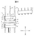
- FIG. 11 is a plan view of the pallet changer of FIG.
- FIG. 12 is a plan view illustrating an example of an operation performed by the pallet transfer device according to the first embodiment.
- FIG. 13 is a plan view showing the operation after FIG.
- FIG. 14 is a perspective view of a pallet exchanging device provided with a pallet transfer device according to the second embodiment of the present invention.
- FIG. 15 is a plan view of the pallet changer of FIG.
- FIG. 16 is an enlarged view of a main part of FIG.
- FIG. 17 is a perspective view of a pallet exchanging device provided with a pallet transfer device according to the third embodiment of the present invention.
- FIG. 11 is a plan view of the pallet changer of FIG.
- FIG. 12 is a plan view illustrating an example of an operation performed by the pallet transfer device according to the first embodiment.
- FIG. 13 is a plan view showing the
- FIG. 18 is a plan view mainly showing the configuration of the traveling body of FIG.
- FIG. 19 is an enlarged view of a main part of FIG.
- FIG. 20 is a front view of a pallet exchanging device showing a modification of FIG.
- FIG. 21 is a plan view mainly showing the configuration of the traveling body of FIG.
- FIG. 22 is a plan view showing an example in which the pallet transfer device according to the present embodiment is applied to a machine tool.
- FIG. 23 is a diagram showing a modification of FIG.
- FIG. 24 is a diagram showing another modification of FIG.
- FIG. 1 is a plan view showing a schematic configuration of machine tool equipment to which a pallet transfer device according to a first embodiment of the present invention is applied
- FIG. 2 is a side view of the machine tool.
- the front-rear direction (Z direction), the left-right direction (X direction), and the up-down direction (Y direction) are defined, and the configuration of each part will be described in accordance with this definition.
- the direction is not limited.
- the machine tool 1 includes a machine tool 1, pallet changers (also called setup stations) 2 and 3 installed at the setup positions on the left and right sides of the machine tool 1 adjacent to the machine tool 1, and the machine tool 1. And a machine control device 4 for controlling the pallet changing devices 2 and 3.
- the pallet P is sequentially transferred from one (left side) pallet changer 2 to the machine tool 1 and from the machine tool 1 to the other (right side) pallet changer 3.
- the pallet transfer device according to the present embodiment is provided in the pallet exchange devices 2 and 3.
- a workpiece W is attached to the pallet P in advance, the workpiece W is transferred integrally with the pallet P, and the workpiece W is processed by the machine tool 1.
- the machine tool 1 shows a state where the pallet P1 is transferred from the pallet changer 2 to the machine tool 1 and the pallet P2 is transferred from the machine tool 1 to the pallet changer 3.
- a workpiece W1 before or during processing is attached to the pallet P1, and a processed workpiece W2 is attached to the pallet P2.
- the machine tool 1 is, for example, a horizontal machining center, and the pallet P is held vertically in the vertical direction.
- the machine tool 1 has a splash guard 11, and the machining area is surrounded by the splash guard 11.
- the splash guard 11 has an opening for carrying the pallet P into and out of the machining area, a door 11a and 11b for opening and closing each opening, and a door opening and closing for opening and closing each door 11a and 11b.
- Motors Ma and Mb are provided. As shown in FIGS.
- the machine tool 1 stands on the first bed 12, the second bed 13 that is spaced apart from the first bed 12 and disposed behind the first bed 12, and the first bed 12.
- a column 14 provided, a spindle head 15 supported by the column 14, and a spindle head 15 that can rotate about a rotation axis O extending in the front-rear direction, and projecting rearward from the rear surface of the column 14
- a table 17 disposed on the second bed 13.
- a tool T is mounted on the tip of the spindle 16 via a tool holder (not shown), and the tool T is rotationally driven by a spindle motor in the spindle head 15.
- the pallet P On the front surface of the table 17, the pallet P is held in a vertical posture via a pallet support portion (a guide roller 53 described later).
- a workpiece W is attached to the front surface of the pallet P so as to face the tool T.
- the column 14 is supported on the upper surface of the first bed 12 so as to be movable in the front-rear direction via a Z-axis linear feed mechanism.
- the spindle head 15 is supported on the rear surface of the column 14 so as to be movable in the vertical direction via a Y-axis linear feed mechanism.
- the table 17 is supported on the upper surface of the second bed 13 so as to be movable in the left-right direction via an X-axis feed mechanism.
- Each of the X-axis, Y-axis, and Z-axis linear feed mechanisms includes, for example, a ball screw, a servo motor that rotationally drives the ball screw, and a guide rail that guides linear movement of the column 14, the spindle head 15, and the table 17. Etc., respectively.
- the tool T and the workpiece W can be relatively moved in the orthogonal three-axis directions (X, Y, and Z-axis directions), and the workpiece W is machined by the relative movement between the tool T and the workpiece W.
- FIG. 3 is a front view of the rear surface of the pallet P (viewed along arrow III in FIG. 2)
- FIG. 4 is a front view of the table 17 facing the pallet P (shown in arrow IV in FIG.
- FIG. 3 is a cross-sectional view of a portion V in FIG. 2.
- a drive motor M ⁇ b> 0 is installed on the upper surface of the table 17.
- the output shaft 51 of the drive motor M0 protrudes forward (see FIG. 2), and a pinion 52 is attached to the tip.
- a plurality of upper and lower guide rollers 53 are attached to the front surface of the table 17 at equal intervals in the left-right direction.
- a rack 55 that meshes with the pinion 52 is formed at the upper end portion of the pallet P over the entire length in the left-right direction.
- a pair of upper and lower grooves 54 are formed on the front surface of the pallet P so as to correspond to the guide rollers 53 over the entire length in the left-right direction. As shown in FIG. 5, the groove portion 54 expands in the vertical direction behind the inlet portion in the back (front) thereof, and convex portions 54 a are formed on both upper and lower sides of the inlet portion.
- a pair of upper and lower guide portions having a substantially L-shaped cross section may be attached to the rear surface of the pallet P so as to face each other to form a pair of upper and lower convex portions.
- a plurality of guide portions having a substantially L-shaped cross section may be provided at equal intervals in the left-right direction instead of being provided over the entire length in the left-right direction.
- the guide roller 53 includes a base portion 53a attached to the front surface of the table 17, a shaft portion 53b extending forward from the base portion 53a, and a roller portion 53c provided at the tip of the shaft portion 53b.
- the roller portion 53c has a substantially disc shape centered on the shaft portion 53b. For this reason, the roller portion 53c protrudes in the vertical and horizontal directions from the shaft portion 53b, and an accommodation space 53d for accommodating the convex portion 53a of the pallet P is formed between the base portion 53a and the roller portion 53c.
- rollers are attached to the upper and lower surfaces and the front surface of the roller portion 53c in order to facilitate movement of the pallet P along the guide roller 53 in the left-right direction.
- a part of the plurality of guide rollers 53 is constituted by a piston that moves the roller portion 53c in the front-rear direction.
- the roller 53c moves rearward by the retracting operation of the piston, the rear surface of the pallet P abuts on the front end surface of the base 53a, and the pallet P can be clamped and fixed to the table 17.
- the clamp portion may not be configured by the guide roller 53 but may be configured by a member different from the guide roller 53. In such a machine tool 1, the groove portion 54 of the pallet P and the guide roller 53 are engaged so as to be movable in the left-right direction.
- the pallet exchanging devices 2 and 3 have pallet support bases 21 and 31 erected in the vertical direction, respectively.
- Drive motors M1 and M2 are installed on the top surfaces of the pallet support tables 21 and 31, respectively, and pinions 52 are attached to the output shafts of the drive motors M1 and M2 in the same manner as the drive motor M0.
- Guide rollers 22 and 32 are provided on the front surfaces of the pallet support bases 21 and 31, respectively.
- the guide rollers 22 and 32 are configured in the same manner as the guide roller 53 of the table 17. That is, a plurality of guide rollers 22 and 32 are provided in pairs in the vertical direction and spaced apart in the left-right direction.
- the guide rollers 22 and 32 engage with the groove portion 54 of the pallet P, and the pallet P is supported by the pallet support bases 21 and 31. Supported by the front of the.
- the pinion 52 is rotated by the drive motors M1 and M2 while the pallet P is supported on the front surface of the pallet support tables 21 and 31, the pallet P is guided to the pallet support tables 21 and 31 while being guided by the guide rollers 22 and 32. Move left and right along.
- the machine control device 4 also controls the start and stop of the machine tool 1 and the operation of a tool changer provided in the machine tool 1. Further, the machine control device 4 has a function of reading and interpreting the NC program and sending a movement command.
- Pallet exchanging devices 2 and 3 in the present embodiment are provided so as to be movable along rails.
- FIG. 6 is a perspective view showing a schematic configuration of the left pallet exchanging device 2. Since the basic configurations of the left and right pallet changers 2 and 3 are the same, only the configuration of the left pallet changer 2 will be described below, and the description of the configuration of the right pallet changer 3 will be omitted. . In FIG.
- FIG. 6 for the sake of convenience, illustration of the drive motors M0 and M1 and the workpiece W is omitted, and only the table 17 is shown as the configuration of the machine tool 1.
- a pair of left and right rails 61 and an inner central rail 62 are laid in the front-rear direction substantially parallel to each other.
- a gear rail 63 having a gear portion 63 a on the upper surface is laid in the front-rear direction substantially parallel to the central rail 62.
- a traveling body 65 is placed on the upper surface of the rail 62.
- the traveling body 65 includes a flat plate portion 66 extending in the horizontal direction, a pair of left and right long plate portions 67 projecting downward from the bottom surface of the flat plate portion 66, and extending in the front-rear direction.
- a tire 68 mounted rotatably at both ends (only the front side is shown) about an axis in the left-right direction, and a guide block 69 provided at the left and right center of the bottom surface of the flat plate portion 66 and at both front and rear ends (only the front side is shown).
- a drive motor 71 attached to the bottom surface of the flat plate portion 66 on the left side of the front guide block 69, and a drive gear 70 that is rotationally driven by the drive motor 71.
- the tire 68 is mounted on the upper surfaces of the left and right rails 61 so as to be able to roll.
- a pallet support 21 is placed on the upper surface of the flat plate portion 66.
- the pallet support base 21 includes a base portion 23 having a substantially rectangular shape in plan view and a base portion 24 erected upward from the front-rear direction center portion of the base portion 23, and the base portion 24 is provided over the entire length in the left-right direction of the base portion 23. It has been.
- the guide roller 22 (FIG. 1) is provided on the front surface of the pedestal 24, and the pallet P is supported on the pedestal 24 while being separated from the base 23.
- a rib 24 a is provided on the rear surface of the base 24.
- the guide block 69 has a pair of left and right rollers 69a, and a central rail 62 is disposed inside the left and right rollers 69a.
- the drive gear 70 meshes with the gear portion 63 a of the gear rail 63.
- the drive motor 71 is controlled by the machine control device 4.
- the rail 61, the center rail 62, and the gear rail 63 are extended from the setup position of the side of the table 1 to the pallet stocker in which the pallet P was stocked. Therefore, the traveling body 65 moves between the pallet stocker and the setup position, and the pallet P arranged in the pallet stocker is conveyed to the setup position.
- the drive motor M1 (FIG. 1) provided on the pallet support base 21 is stopped. In this state, the movement of the pallet P in the left-right direction is prevented by the engagement of the pinion 52 at the tip of the drive motor M1 and the rack 55 at the top of the pallet.
- FIG. 7 is a perspective view showing this transfer state
- FIG. 8 is a plan view.
- the guide roller 22 on the front surface of the pallet support base 21 is not shown. 7 and 8, the groove 54 on the rear surface of the pallet P is engaged with both the guide roller 22 on the front surface of the pallet support 21 and the guide roller 53 on the front surface of the table 17.
- the mounting surfaces of the pallet P defined by the guide rollers 22 and 53 are defined as a first engagement surface S1 and a second engagement surface S2, respectively, and the pallet P defined by the groove portion 54 is defined.
- the surface to be attached is defined as the engaged surface S0.
- the first engagement surface S1 and the second engagement surface S2 are, for example, vertical surfaces extending in the left-right direction along the front surfaces of the guide rollers 22 and 53, and the engaged surface S0 is formed along the bottom surface of the groove portion 54.
- the first engagement surface S1 and the second engagement surface S2 are parallel to the front surfaces of the pallet support base 21 and the table 17, respectively, and the orientations of the pallet support base 21 and the table 17 are represented by the engagement surfaces S1 and S2, respectively.
- the engaged surface S0 is parallel to the rear surface of the pallet P, and the direction of the pallet P is represented by the engaged surface S0.
- the first engagement surface S1 and the second engagement surface S2 are on the same plane, and the directions of the engagement surfaces S1 and S2 coincide with the direction of the engaged surface S0. Yes. That is, the first engagement surface S1 and the second engagement surface S2 face each other in a parallel state without being inclined with respect to the engaged surface S0.
- the engaging surfaces S1 and S2 and the engaged surface S0 are shown on the same surface. However, in this specification, it is also defined that they are in a parallel state.
- the groove portion 54 of the pallet P transferred to the right from the pallet support base 21 contacts the guide roller 53 of the table 17. Engage smoothly.
- the pallet P can be easily transferred from the pallet support 21 to the table 17 by the drive motor M1.
- the table 17 is provided in the machine tool 1, whereas the pallet support base 21 is provided in the pallet changer 2.
- the second engagement surface S2 is inclined with respect to the first engagement surface S1.
- the guide roller 53 is deformed and it becomes difficult to transfer the pallet P along the guide roller 53.
- the direction of the first engagement surface S1 matches the direction of the second engagement surface S2, in other words, the second engagement with respect to the first engagement surface S1. It is necessary to change the orientation of the pallet support 21 so that the inclination of the mating surface S2 becomes zero.
- not only a great amount of labor is required, but also a lot of time is consumed for transporting the pallet P.
- the pallet P is long in the left-right direction, it is difficult to transfer the pallet P even if the inclination between the engagement surfaces S1 and S2 is very small.
- FIG. 10 is a perspective view of the pallet exchanging apparatus 2 having the pallet transfer apparatus according to the first embodiment
- FIG. 11 is a plan view. In FIG. 10, the pallet P, the guide roller 22, and the drive motor M1 are not shown, and in FIG. 11, the guide roller 22 and the drive motor M1 are not shown.
- FIG. 11 shows a moving state in which the pallet exchanging device 2 is moving toward the setup position.
- a shaft portion 25 is provided in the right front end portion of the base portion 23 of the pallet support base 21 in the vertical direction, and the pallet support base 21 has the shaft portion 25 on the upper surface of the traveling body 65. It is supported so that rotation is possible.
- Tires 26 are respectively attached to the left front end, left rear end, and right rear end of the bottom surface of the base 23, and the tire 26 can roll on the upper surface of the traveling body 65.
- Fixed cylinders 27 are respectively attached to the left and right ends of the upper surface of the flat plate portion 66 of the traveling body 65 on both the front and rear sides of the base portion 23.
- the fixed cylinder 27 has a piston 27 a that can extend and contract in the front-rear direction toward the base 23.
- a piston 27 a that can extend and contract in the front-rear direction toward the base 23.
- the rotation of the pallet support base 21 is prevented.
- the distal end portion of the piston 27a is separated from the front and rear end surfaces of the base portion 23 due to the contraction of the piston 27a, the rotation of the pallet support base 21 is permitted.
- the expansion / contraction operation of the piston 27 a is controlled by the machine control device 4. Main operations of the pallet transfer device for the machine tool according to the first embodiment will be described. As shown in FIG.
- the pallet support 21 rotates on the traveling body in the direction of arrow A with the shaft portion 25 as a fulcrum, and the first engagement surface S1 is on the extended surface of the second engagement surface S2. Move to. As a result, the engaged surface S0 and the second engaging surface S2 are in a parallel state, the contact force between the guide roller 53 and the groove portion 54 is reduced, and the pallet P can be smoothly transferred to the table 17. On the other hand, although not shown, when the pallet P is transferred from the table 17 to the pallet changer 3 after the processing of the workpiece W is finished, the drive motor M0 of the table 17 is driven. As a result, the pallet P starts to move toward the pallet changer 3.
- the pallet exchanging apparatus 3 is supported on the traveling body 65 so that the pallet support base 31 is rotatable about the shaft portion 25.
- the engaging surface (referred to as the third engaging surface) of the guide roller 32 (FIG. 1) is inclined with respect to the second engaging surface S2 of the guide roller 53, the groove 54 and the guide roller 32 Due to this contact force, the pallet support base 31 rotates on the traveling body 65, and the inclination of the third engagement surface of the guide roller 32 is corrected. Thereby, the pallet P can be smoothly transferred to the workpiece changer 3.
- the following operational effects can be achieved.
- the pallet support 21 of the pallet changer 2 is supported on the traveling body 65 so as to be rotatable in a horizontal plane with the shaft portion 25 as a fulcrum. Accordingly, when the second engagement surface S2 is inclined with respect to the first engagement surface S1, the inclination can be corrected by the contact force between the guide roller 53 and the groove portion 54. As a result, deformation of the guide roller 53 can be suppressed and the pallet P can be smoothly transferred from the pallet changer 2 to the table 17. (2) Since the inclination of the second engagement surface S2 with respect to the first engagement surface S1 is automatically corrected by the contact force between the guide roller 53 and the groove portion 54, an actuator for rotating the pallet support base 21, etc. Is unnecessary, and the pallet transfer device can be configured at low cost.
- FIG. 14 is a perspective view of the pallet exchanging apparatus 2 having the pallet transfer apparatus according to the second embodiment
- FIG. 15 is a plan view.
- the pallet support base 21 is fixed to the upper surface of the traveling body 65, unlike the first embodiment.
- a pallet P is supported on the front surface of the pallet support 21 via a guide roller 22 so as to be slidable in the left-right direction.
- a drive motor M1 (FIG.
- a pair of left and right support rollers 35 and 36 are attached to the upper surface of the pallet support base 21.
- the left and right support rollers 35 and 36 are respectively a pair of front and rear rollers that are provided so as to be rotatable about a substantially rotational axis in the vertical direction and a substantially L-shaped arm 37 and 38 that passes above the pallet P and extends forward. 39,40.
- FIG. 16 is a perspective view of the support roller 36.
- the arm 38 includes a base portion 38a and a plate portion 38b protruding forward from the upper surface of the base portion 38a.
- a guide groove 38c is provided on the bottom surface of the plate portion 38b in the front-rear direction, and a slider 41 is slidably engaged with the guide groove 38c.
- a stopper 42 that restricts the movement of the slider 41 is provided at the bottom front end of the plate portion 38b.
- a pair of rollers 40 is rotatably supported by the slider 41 so as to be separated from each other in the front-rear direction, and a pallet P is interposed between the rollers 40 as shown in FIG.
- the base 38a of the arm 38 has a built-in fixed cylinder 43, and a piston 43a that can extend and contract in the front-rear direction protrudes from the front surface of the base 38a.
- the expansion / contraction operation of the piston 43a is controlled by the machine control device 4. By this control, the piston 43a is extended forward except when the pallet P is transferred from the pallet changer 2 to the table 17.
- the slider 41 is pushed forward, the front end surface of the slider 41 abuts against the stopper 42, and the slider 41 is fixed to the arm 38.
- the rotation of the pallet P with respect to the pallet support 21 is prohibited, and rattling of the pallet P can be suppressed.
- the piston 43a is retracted rearward.
- the slider 41 can slide in the front-rear direction.
- the drive motor M1 is driven to start the transfer of the pallet P.
- the engagement surface S1 of the pallet support 21 and the engagement surface S2 of the table 17 are not on the same surface, a contact force is generated between the guide roller 53 of the table 17 and the groove portion 54 of the pallet P.
- a pressing force forward or backward acts on the pallet P.
- the roller 40 of the support roller 36 moves in the front-rear direction with respect to the base 24 of the pallet support base 21, and the pallet P rotates in the direction of arrow A with the support roller 35 as a fulcrum as shown in FIG. To do.
- the direction of the engaged surface S0 is changed, and the pallet P can be smoothly transferred to the table 17.
- the pallet P is provided to be rotatable with respect to the pallet support base 21 by the support rollers 35 and 36.
- the guide roller 22 and the groove portion 54 are provided in the same manner as in the first embodiment. If comprised, the rotation range of the pallet P will be restrict
- the pallet support portion on the front surface of the pallet support base 21 may be configured so that the guide roller 22 moves in the front-rear direction together with the pallet P.
- the direction of the engaged surface S0 is changed by fixing the pallet support 21 to the upper surface of the traveling body 65 and providing the traveling body 65 so as to be rotatable with respect to the rail 61.
- FIG. 17 is a perspective view of a pallet exchanging apparatus 2 having a pallet transfer apparatus according to the third embodiment
- FIG. 18 is a plan view mainly showing the configuration of the traveling body of FIG. 17, and FIG. FIG.
- the same parts as those in FIGS. 1 to 13 are denoted by the same reference numerals, and differences from the first embodiment will be mainly described below.
- a pair of front and rear guide blocks 69 moving along the central rail 62 is provided below the traveling body 65.
- the front guide block 69 is fixed to the bottom surface of the traveling body 65.
- a guide rail 75 is fixed to the bottom surface of the rear end portion of the traveling body 65, and the rear guide block 69 engages with a guide groove 75a of the guide rail 75 so as to be slidable in the left-right direction.
- a pair of fixed cylinders 76 are fixed to the left and right sides of the guide block 69 at the bottom of the traveling body 65, and pistons 77 protrude from the left and right inner surfaces of each fixed cylinder 76.
- the expansion / contraction operation of the piston 77 is controlled by the machine control device 4. By this control, the piston 77 is extended inward in the left-right direction except when the pallet P is transferred from the pallet changer 2 to the table 17.
- the end surface of the piston 77 contacts the left and right outer surfaces of the guide block 69, and the guide rail 75 cannot slide with respect to the guide block 69.
- the rotation of the traveling body 65 with respect to the rail 61 is prohibited, and rattling of the pallet P can be suppressed.
- the piston 77 is retracted outward in the left-right direction. Thereby, the restraint of the guide rail 75 with respect to the guide block 69 is released, and the guide rail 75 can move in the left-right direction.
- FIG. 20 is a front view (viewed from the front) showing another configuration that enables the traveling body 65 to rotate, and FIG.
- gear rails 63 are laid on the outer sides of the left and right rails 61 in the left-right direction.
- Drive motors 71 a and 71 b are attached to the traveling body 65 at the left and right ends corresponding to the respective gear rails 63.
- Drive gears 70 mesh with the gear portions 63a of the gear rails 63, and the drive gears 70 are driven to rotate by drive motors 71a and 71b, respectively.
- the traveling body 65 is moved to the setup position, the drive motors 71 a and 71 b are synchronously controlled by the machine control device 4.
- the pallet P can be transported without rattling.
- the drive motors 71a and 71b are prevented from rotating the right drive motor 71b and the left drive motor 71a is in a free rotation state. Be controlled.
- the traveling body 65 can rotate in the direction of arrow A with the meshing portion of the drive gear 70 of the drive motor 71b and the gear portion 63a of the gear rail 63 as a fulcrum, and the orientation of the pallet P can be changed.
- the pallet exchanging devices 2 and 3 are provided with the turning mechanism.
- FIG. 22 is a plan view showing an example thereof.
- the table support base 18 is supported on the upper surface of the second bed 13 via an X-axis feed mechanism so as to be movable in the left-right direction.
- the table 17 is rotatably supported on the upper surface of the table support base 18 in the same manner as the pallet support base 21 of FIG. That is, the shaft portion 25 is attached to the left front end portion of the table 17, and the tires 82 are attached to the left rear end portion, the right front end portion, and the right rear end portion, respectively.
- a fixed cylinder 27 is attached to the upper right end portion of the table support base 18 so as to sandwich the table 17 in the front-rear direction.
- the drive of the fixed cylinder 27 is controlled by the machine control device 4, and the piston 27a of the fixed cylinder 27 is extended during workpiece processing. Thereby, the table 17 is hold
- the piston 27a of the fixed cylinder 27 is retracted. Thereby, the table 17 can be rotated about the shaft portion 25 as a fulcrum, and the pallet P can be easily transferred from the pallet changer 2 to the machine tool 1 and from the machine tool 1 to the pallet changer 3.
- the pallet support base 21 of the pallet changer 2 is the first base
- the table 17 of the machine tool 1 is the second base, and the pallet P is moved from the first base to the second base.
- FIG. 23 is a plan view of the entire machine tool facility showing an example thereof.
- a plurality of pallet stockers 8 are arranged in the same direction on the movement path of the pallet exchanging device 2, and each pallet stocker 8 holds a pallet P.
- the pallet changer 2 is provided with a rotating mechanism as described above so that the pallet P can be easily transferred between the two. be able to.
- the pallet stocker 8 may be provided with a turning mechanism.
- the pallet P can be sequentially conveyed to different machine tools 1a to 1c.
- the pallet support base 21 in the pallet changer 2 may be provided on the traveling body 65 so as to be turnable by a motor drive or the like.
- a plurality of pallet stockers 8 can be arranged radially around the pallet exchanging device 2. While providing the rotation mechanism in the pallet exchange apparatus 2, you may comprise the pallet support stand 21 so that rotation is possible. In this case, the turning operation of the pallet support base 21 may be stopped, and the pallet P may be transferred while the pallet support base 21 is rotatably supported by a rotation mechanism.
- the rack 55 is formed on the upper surface of the pallet P. However, the rack 55 may be formed at the center in the height direction of the pallet P, and the drive motors M0, M1, M2 are also supported by the table 17 and the pallet. You may make it attach to the center part of the bases 21 and 31.
- the first engagement surface S 1 is defined by the guide roller 22 of the pallet support 21
- the second engagement surface S 2 is defined by the guide roller 53 of the table 17, and the engaged surface S 0 is defined by the groove 54 of the pallet P.
- the pallet P may be attached to the pallet support 21 and the table 17 in a manner other than the engagement, and the configurations of the first attachment portion, the second attachment portion, and the attachment portion are not limited to those described above. . Therefore, in addition to the first engagement surface S1, the second engagement surface S2, and the mounted surface S0, a first mounting surface, a second mounting surface, and a mounted surface may be formed.
- a first mounting surface and a second mounting surface may be formed on the pallet support 21 and the front surface of the table 17, respectively, and a mounted surface may be formed on the rear surface of the pallet P.
- the tire 82 is attached to the pallet support base 21 and the pallet support base 21 is rotatably supported on the traveling body 65 with the shaft portion 25 as a fulcrum. If the pallet support tables 21 and 31 or the table 17 are rotatably supported so that the direction of the first engagement surface S1 or the second engagement surface S2 is changed by the contact force with Is not limited to this.
- the pallet P is rotatably supported from the pallet support base 21 with the support roller 35 as a fulcrum by the support roller 36 having the slider 41 slidable in the front-rear direction with respect to the arm 38.
- the pallet P is rotated on the pallet support bases 21 and 31 or the table 17 so that the direction of the engaged surface S0 of the pallet P with respect to the pallet support bases 21 and 31 or the table 17 is changed by the contact force between the pallet P and the table 17. If it supports so that movement is possible, the structure of a pallet support part will not be restricted to this.
- the guide rail 75 is provided on the bottom surface of the traveling body 65 so as to be slidable in the left-right direction with respect to the guide block 69, and the traveling body 65 is rotatably supported on the rail 61. If the traveling body 65 is rotatably supported on the rail 61 so that the direction of the first engagement surface S1 or the second engagement surface S2 is changed by the contact force between P and the table 17, the movable body is supported.
- the configuration of the part is not limited to this.
- a support mechanism is provided by means other than the above-described base support part, pallet support part and moving body support part. It may be configured.
- the movement path of the pallet P is generated by the rail 61 from the setup position to the pallet stocker.
- the movement path may be generated from the setup position to another separated position.
- the route generation unit may be configured by other than the rail 61. Therefore, the configuration of the moving body that moves integrally with the work support bases 21 and 31 along the movement path is not limited to the traveling body 65.
- the rotation of the work support bases 21 and 31, the table 17 or the pallet P is prevented by the fixed cylinders 27, 43a, 43 and 76 or by the rotation control of the drive motor 70.
- the configuration of the movement preventing unit is not limited to this. According to the present invention, the mounting surface of the pallet and the second pallet are moved by the contact force acting between the pallet and the second pedestal as the pallet is transferred from the first pedestal to the second pedestal.
- the first table, the second table, and the pallet Since at least one of the first table, the second table, and the pallet is rotatably supported so that the directions of the pallet mounting surfaces of the table coincide with each other, the first table and the second table Even if there is an inclination between the pallet mounting surfaces of the table, the inclination can be automatically corrected and the pallet can be transferred smoothly.
Landscapes
- Engineering & Computer Science (AREA)
- Mechanical Engineering (AREA)
- Feeding Of Workpieces (AREA)
Abstract
Description
この特許文献1記載の装置では、段取り台と工作機械のテーブルとにそれぞれ鉛直方向にパレット取付け面を形成するとともに、各パレット取付け面にパレットの移送方向に沿ってそれぞれパレット案内レールを設ける。そして、段取り台のパレット取付け面に鉛直姿勢でパレットを保持し、保持したパレットをモータの駆動によりパレット案内レールを介して工作機械のテーブルへと移送する。その後、テーブルのパレット取付け面にパレットを固定し、ワークの加工を行う。
本発明は、互いに隣接した第1の台から第2の台へワーク取付用のパレットを移送する工作機械のパレット移送装置であって、第1の台は、パレットの移送方向に沿って設けられ、第1の取付け面を規定する第1の取付け部を有し、第2の台は、パレットの移送方向に沿って設けられ、第2の取付け面を規定する第2の取付け部を有し、パレットは、パレットの移送方向に沿って設けられ、第1の取付け部および第2の取付け部に取付け可能な被取付け部を有し、第1の取付け面に沿った第1の台から第2の台へのパレットの移送に伴い、被取付け部と第2の取付け部との接触力によって、被取付け部によって規定される被取付け面と第2の取付け面の向きが互いに一致するように第1の台、第2の台およびパレットのうち、少なくとも1つを回動可能に支持する支持機構を備えることを特徴とする。
図2は、図1の工作機械の側面図である。
図3は、図2の矢視III図である。
図4は、図2の矢視IV図である。
図5は、図2のV部断面図である。
図6は、パレット交換装置の一例を示す斜視図ある。
図7は、図6のパレット交換装置によるパレットの移送状態を示す斜視図である。
図8は、図6のパレット交換装置によるパレットの移送状態を示す平面図である。
図9は、パレットの移送時の問題点を説明する図である。
図10は、本発明の第1の実施の形態に係るパレット移送装置が設けられたパレット交換装置の斜視図である。
図11は、図10のパレット交換装置の平面図である。
図12は、第1の実施の形態に係るパレット移送装置による動作の一例を示す平面図である。
図13は、図12の後の動作を示す平面図である。
図14は、本発明の第2の実施の形態に係るパレット移送装置が設けられたパレット交換装置の斜視図である。
図15は、図14のパレット交換装置の平面図である。
図16は、図14の要部拡大図である。
図17は、本発明の第3の実施の形態に係るパレット移送装置が設けられたパレット交換装置の斜視図である。
図18は、図17の主に走行体の構成を示す平面図である。
図19は、図18の要部拡大図である。
図20は、図17の変形例を示すパレット交換装置の正面図である。
図21は、図20の主に走行体の構成を示す平面図である。
図22は、工作機械に本実施の形態に係るパレット移送装置を適用した例を示す平面図である。
図23は、図1の変形例を示す図である。
図24は、図1の別の変形例を示す図である。
以下、図1~図13を参照して、本発明による工作機械のパレット移送装置の第1の実施の形態を説明する。図1は、本発明の第1の実施の形態に係るパレット移送装置が適用される工作機械設備の概略構成を示す平面図であり、図2は、工作機械の側面図である。なお、以下では、便宜上図示のように前後方向(Z方向)、左右方向(X方向)および上下方向(Y方向)を定義し、この定義に従い各部の構成を説明するが、各部の構成は図示の方向に限定されない。
図1の工作機械設備は、工作機械1と、工作機械1に隣接して工作機械1の左右両側の段取り位置に設置されたパレット交換装置(段取りステーションとも呼ぶ)2,3と、工作機械1およびパレット交換装置2,3を制御する機械制御装置4とを備える。この工作機械設備においては、一方(左側)のパレット交換装置2から工作機械1へ、および工作機械1から他方(右側)のパレット交換装置3へと順次パレットPが移送される。本実施の形態に係るパレット移送装置は、パレット交換装置2,3に設けられる。
パレットPには予めワークWが取り付けられ、パレットPと一体にワークWが移送され、工作機械1によってワークWが加工される。なお、図1では、パレット交換装置2から工作機械1にパレットP1が移送され、かつ、工作機械1からパレット交換装置3にパレットP2が移送された状態を示している。パレットP1には加工前あるいは加工中のワークW1が取り付けられ、パレットP2には加工済みのワークW2が取り付けられている。
工作機械1は、例えば横形のマシニングセンタであり、パレットPが鉛直方向に向けて縦置きに保持されている。工作機械1は、スプラッシュガード11を有し、スプラッシュガード11によって加工領域が包囲されている。スプラッシュガード11には、加工領域にパレットPを搬入および加工領域からパレットPを搬出するための開口部と、各開口部を開閉するドア11a,11bと、各ドア11a,11bを開閉するドア開閉モータMa,Mbとが設けられている。
図1,2に示すように工作機械1は、第1ベッド12と、第1ベッド12から離間して第1ベッド12の後方に配置された第2ベッド13と、第1ベッド12上に立設されたコラム14と、コラム14に支持された主軸頭15と、前後方向に延在する回転軸線Oを中心として主軸頭15に回転可能に、かつ、コラム14の後面から後方に突出して支持された主軸16と、第2ベッド13上に配置されたテーブル17とを有する。主軸16の先端部には、工具ホルダ(不図示)を介して工具Tが装着され、工具Tは主軸頭15内のスピンドルモータにより回転駆動される。テーブル17の前面には、パレット支持部(後述のガイドローラ53)を介してパレットPが鉛直姿勢に保持されている。パレットPの前面には、工具Tに対向してワークWが取り付けられている。
コラム14は、Z軸用直線送り機構を介して第1ベッド12の上面に前後方向に移動可能に支持されている。主軸頭15は、Y軸用直線送り機構を介してコラム14の後面に上下方向に移動可能に支持されている。テーブル17は、X軸用送り機構を介して第2ベッド13の上面に左右方向に移動可能に支持されている。X軸用、Y軸用、Z軸用の各直線送り機構は、例えばボールねじと、ボールねじを回転駆動するサーボモータと、コラム14、主軸頭15およびテーブル17の直線移動を案内する案内レール等によりそれぞれ構成される。この構成により、工具TとワークWとが直交3軸方向(X,Y,Z軸方向)に相対移動可能となり、工具TとワークWとの相対移動によりワークWが加工される。
図3は、パレットPの後面の正面図(図2の矢視III図)であり、図4は、パレットPに対向するテーブル17の正面図(図2の矢視IV図)、図5は、図2のV部断面図である。
図4に示すように、テーブル17の上面には、駆動モータM0が設置されている。駆動モータM0の出力軸51は前方に突出し(図2参照)、その先端部にピニオン52が取り付けられている。また、テーブル17の前面には、上下一対のガイドローラ53が左右方向に等間隔に離間して複数取り付けられている。
図3に示すように、パレットPの上端部には、ピニオン52に噛合するラック55が左右方向全長にわたって形成されている。また、パレットPの前面には、ガイドローラ53に対応し、上下一対の溝部54が左右方向全長にわたって形成されている。図5に示すように溝部54は、その奥方(前方)において入口部よりも上下方向に拡大し、入口部の上下両側に凸部54aが形成されている。なお、パレットPの後面に断面略L字形状の上下一対のガイド部を互いに向かい合わせに取り付けて、上下一対の凸部を形成してもよい。この場合、断面略L字形状のガイド部を左右方向全長にわたって設けるのではなく、左右方向等間隔に複数設けるようにしてもよい。
図5において、ガイドローラ53は、テーブル17の前面に装着された基部53aと、基部53aから前方に延在する軸部53bと、軸部53bの先端に設けられたローラ部53cとを有する。ローラ部53cは、軸部53bを中心とした略円板形状をなしている。このため、ローラ部53cは、軸部53bよりも上下左右方向に突出し、基部53aとローラ部53cとの間に、パレットPの凸部53aを収容する収容空間53dが形成されている。図示は省略するが、ローラ部53cの上下面および前面には、ガイドローラ53に沿ったパレットPの左右方向の移動を容易にするためにローラが取り付けられている。
複数のガイドローラ53のうち一部は、ローラ部53cを前後方向に移動するピストンによって構成されている。このピストンの縮退動作によりローラ部53cが後方に移動し、パレットPの後面が基部53aの前端面に当接して、パレットPをテーブル17にクランプして固定することができる。なお、クランプ部をガイドローラ53によって構成するのではなく、ガイドローラ53とは別部材によってクランプ部を構成してもよい。
このような工作機械1では、パレットPの溝部54とガイドローラ53とが左右方向に移動可能に係合している。このためクランプ部によるクランプを解除した状態で、駆動モータM0によりピニオン52を回転させると、ピニオン52に係合しているラック55が移動する。これによりパレットPは、ガイドローラ53に案内されながらテーブル17に沿って左右方向に移動する。
図1において、パレット交換装置2,3は、それぞれ鉛直方向に立設されたパレット支持台21,31を有する。各パレット支持台21,31の上面にはそれぞれ駆動モータM1,M2が設置され、各駆動モータM1,M2の出力軸には、駆動モータM0と同様、ピニオン52が取り付けられている。
各パレット支持台21,31の前面には、ガイドローラ22,32が設けられている。ガイドローラ22,32は、テーブル17のガイドローラ53と同様に構成されている。すなわち、各ガイドローラ22,32はそれぞれ上下一対づつ、かつ左右方向に離間して複数設けられ、ガイドローラ22,32がパレットPの溝部54に係合し、パレットPはパレット支持台21,31の前面に支持される。パレット支持台21,31の前面にパレットPを支持した状態で、駆動モータM1,M2によりピニオン52を回転させると、パレットPは、ガイドローラ22,32に案内されながらパレット支持台21,31に沿って左右方向に移動する。
図1のドア開閉モータMa,Mbおよび駆動モータM0,M1,M2は、機械制御装置4により制御される。機械制御装置4は、工作機械1の起動および停止や、工作機械1に設けられた工具交換装置の動作も制御する。さらに機械制御装置4は、NCプログラムを読み取り解釈し、移動指令を送出する機能も有する。
本実施の形態におけるパレット交換装置2,3は、レールに沿って移動可能に設けられる。図6は、左側のパレット交換装置2の概略構成を示す斜視図である。なお、左右のパレット交換装置2,3の基本的構成は同一であるため、以下では、左側のパレット交換装置2の構成のみを説明し、右側のパレット交換装置3の構成については説明を省略する。また、図6では、便宜上、駆動モータM0,M1およびワークWの図示を省略するとともに、工作機械1の構成としてテーブル17のみを示している。
図6に示すように、工作機械1(テーブル17)の側方には、左右一対のレール61とその内側の中央レール62とが互いに略平行に前後方向にかけて敷設されている。中央レール62の左方には、上面にギア部63aを有するギアレール63が、中央レール62に対して略平行に前後方向にかけて敷設されている。レール62の上面には走行体65が載置されている。
走行体65は、水平方向に延在する平板部66と、平板部66の底面から下方に突出し、前後方向に延在する左右一対の長板部67と、長板部67の左右外側かつ前後両端部(前側のみ図示)に、左右方向の軸線を中心として回転可能に取り付けられたタイヤ68と、平板部66の底面の左右中央かつ前後両端部(前側のみ図示)に設けられたガイドブロック69と、前側のガイドブロック69の左方にて平板部66の底面に取り付けられた駆動モータ71と、駆動モータ71により回転駆動する駆動ギア70とを有する。タイヤ68は、左右のレール61の上面に転動可能に載置されている。
平板部66の上面にはパレット支持台21が載置されている。パレット支持台21は、平面視略矩形状の基部23と、基部23の前後方向中央部から上方に立設された台部24とを有し、台部24は基部23の左右方向全長にわたって設けられている。ガイドローラ22(図1)は台部24の前面に設けられ、パレットPは、基部23から離間して台部24に支持されている。なお、台部24の後面にはリブ24aが設けられている。
ガイドブロック69は、左右一対のローラ69aを有し、左右のローラ69aの内側に中央レール62が配設されている。これにより走行体65の左右方向の位置が規制され、タイヤ68はレール上面から脱落することなくレール61上を転動可能となる。駆動ギア70はギアレール63のギア部63aに噛合している。駆動モータ71により駆動ギア70が回転すると、走行体65がレール61に沿って前後方向に移動する。駆動モータ71は機械制御装置4によって制御される。
なお、図示は省略するが、レール61、中央レール62およびギアレール63は、テーブル1の側方の段取り位置から例えばパレットPがストックされたパレットストッカまで延びている。したがって、走行体65はパレットストッカと段取り位置との間を移動し、パレットストッカに配置されたパレットPが段取り位置まで搬送される。
このパレットPの搬送時には、パレット支持台21に設けられた駆動モータM1(図1)を停止させる。この状態では、駆動モータM1の先端部のピニオン52とパレット上端部のラック55との噛合により、パレットPの左右方向の移動が阻止される。段取り位置に搬送されたパレットPは、駆動モータM1の回転によりテーブル17に移送される。図7は、この移送状態を示す斜視図であり、図8は、平面図である。なお、図7では、パレット支持台21の前面のガイドローラ22の図示を省略している。
図7,8では、パレットPの後面の溝部54がパレット支持台21の前面のガイドローラ22とテーブル17の前面のガイドローラ53の双方に係合している。以下では、図8に示すようにガイドローラ22,53によって規定されるパレットPの取付け面をそれぞれ第1係合面S1および第2係合面S2と定義し、溝部54によって規定されるパレットPの被取付け面を被係合面S0と定義する。
第1係合面S1と第2係合面S2は、例えばガイドローラ22,53の前面に沿って左右方向に延びる鉛直面であり、被係合面S0は、溝部54の底面に沿って左右方向に延びる鉛直面である。第1係合面S1および第2係合面S2はそれぞれパレット支持台21およびテーブル17の前面に平行であり、各係合面S1,S2によってそれぞれパレット支持台21およびテーブル17の向きが表される。被係合面S0はパレットPの後面に平行であり、被係合面S0によってパレットPの向きが表される。
図7,8においては、第1係合面S1と第2係合面S2が互いに同一面上に存在し、これら係合面S1,S2の向きは被係合面S0の向きに一致している。すなわち、第1係合面S1と第2係合面S2は被係合面S0に対して傾くことなく平行状態に対向している。なお、図8では、係合面S1,S2と被係合面S0とが同一面上に表されているが、本明細書では、この場合も平行状態にあると定義する。
このように第1係合面S1と第2係合面S2が互いに同一面上にあると、パレット支持台21から右方に移送されたパレットPの溝部54は、テーブル17のガイドローラ53にスムーズに係合する。このため、駆動モータM1によりパレットPをパレット支持台21からテーブル17に容易に移送することができる。
ところで、テーブル17は工作機械1に設けられているのに対し、パレット支持台21はパレット交換装置2に設けられている。このため、各部品の組立誤差やがたつき等に起因して第1係合面S1と第2係合面S2を精度よく互いに同一面上に形成することは困難であり、例えば図9に示すように第2係合面S2が第1係合面S1に対して傾く。この状態で、パレットPをテーブル17に向けて移送すると、ガイドローラ53の端部(図5のローラ部53c)が溝部54の縁部(例えば図5の凸部54aの背面)に接触し、ガイドローラ53に過大な負荷が作用する。その結果、ガイドローラ53が変形し、ガイドローラ53に沿ったパレットPの移送が困難となる。
これを防止するためには、例えばクレーン等を用いて、第1係合面S1の向きが第2係合面S2の向きと一致するように、換言すると第1係合面S1に対する第2係合面S2の傾きが0となるように、パレット支持台21の向きを変更する必要がある。しかしながら、この場合には多大な労力が必要となるだけでなく、パレットPの搬送に多くの時間を消費する。とくに、パレットPが左右方向に長尺であると、係合面S1,S2同士の傾きが微小であってもパレットPの移送が困難となる。したがって、係合面S1,S2を精度よく一致させる必要があり、パレットPの搬送に一層多くの時間を費やす。
そこで、本実施の形態では、以下のようにパレット交換装置2,3にパレット移送装置を設けて、パレット支持台21を走行体65上に回動可能に支持する。これにより、各係合面S1,S2の向きを互いに同一とし、パレットPの移送を容易にする。
図10は、第1の実施の形態に係るパレット移送装置を有するパレット交換装置2の斜視図であり、図11は、平面図である。なお、図10では、パレットPとガイドローラ22と駆動モータM1の図示を省略し、図11では、ガイドローラ22と駆動モータM1の図示を省略している。図11は、パレット交換装置2が段取り位置に向けて移動している移動状態を示している。
図10,11に示すように、パレット支持台21の基部23の右前端部には鉛直方向に向けて軸部25が設けられ、パレット支持台21は、走行体65の上面に軸部25を介して回動可能に支持されている。基部23の底面の左前端部、左後端部および右後端部にはそれぞれタイヤ26が取り付けられ、タイヤ26は走行体65の上面を転動可能である。
走行体65の平板部66の上面左端部には、基部23の前後両側にそれぞれ固定シリンダ27が取り付けられている。固定シリンダ27は、基部23に向けて前後方向に伸縮可能なピストン27aを有する。ピストン27aの伸長によりピストン27aの先端部が基部23の前後両端面に当接すると、パレット支持台21の回動が阻止される。一方、ピストン27aの縮退によりピストン27aの先端部が基部23の前後両端面から離間すると、パレット支持台21の回動が許可される。ピストン27aの伸縮動作は機械制御装置4によって制御される。
第1の実施の形態に係る工作機械のパレット移送装置の主要な動作を説明する。図11に示すように、レール61に沿って走行体65を移動させるときは、固定シリンダ27のピストン27aが伸長される。これによりパレット支持台21の回動が阻止され、パレット支持台21を走行体65上に固定することができ、パレットPのがたつきを抑えることができる。
図12に示すように、走行体65が工作機械1の側方の段取り位置に到達すると、パレット支持台21の駆動モータM1を駆動する。これによりパレットPがガイドローラ22に案内されながらテーブル17に向けて移動を開始する。パレットPの移動時には、固定シリンダ27のピストン27aを縮退し、パレット支持台21を、軸部25を支点に回動可能な状態とする。
このとき、テーブル17の第2係合面S2がパレット支持台21の第1係合面S1に対して傾いていると、テーブル17の第2係合面S2とパレットPの被係合面S0とが平行状態にない。このため、パレットPの移送開始後の初期状態において、ガイドローラ53の端部がパレットPの溝部54に接触し、ガイドローラ53と溝部54との間に互いに反力(接触力)が作用する。この接触力により、パレットPには、被係合面S0と第2係合面S2とが平行状態となるような前方または後方への押付力が作用する。これにより図13に示すように、パレット支持台21は軸部25を支点にして走行体上を矢印A方向に回動し、第1係合面S1が第2係合面S2の延長面上に移動する。その結果、被係合面S0と第2係合面S2とが平行状態となり、ガイドローラ53と溝部54との接触力が減少し、パレットPをスムーズにテーブル17に移送することができる。
一方、図示は省略するが、ワークWの加工終了後、テーブル17からパレット交換装置3へパレットPを移送する場合には、テーブル17の駆動モータM0を駆動する。これによりパレットPがパレット交換装置3へ向けて移動を開始する。この場合、パレット交換装置3もパレット交換装置2と同様、パレット支持台31が軸部25を支点にして走行体65上に回動可能に支持されている。このため、ガイドローラ53の第2係合面S2に対しガイドローラ32(図1)の係合面(第3係合面と呼ぶ)が傾いている場合には、溝部54とガイドローラ32との接触力によりパレット支持台31が走行体65上を回動し、ガイドローラ32の第3係合面の傾きが修正される。これによりパレットPをスムーズにワーク交換装置3へ移送することができる。
本実施の形態によれば以下のような作用効果を奏することができる。
(1)パレット交換装置2のパレット支持台21を、軸部25を支点にして走行体65上に水平面内で回動可能に支持するようにした。これにより、第1係合面S1に対して第2係合面S2が傾いている場合に、ガイドローラ53と溝部54との接触力によりその傾きを修正できる。その結果、ガイドローラ53の変形を抑え、パレットPをパレット交換装置2からテーブル17にスムーズに移送することができる。
(2)ガイドローラ53と溝部54との接触力により第1係合面S1に対する第2係合面S2の傾きが自動的に修正されるので、パレット支持台21を回動させるためのアクチュエータ等が不要であり、パレット移送装置を安価に構成できる。
(3)走行体65上にタイヤ82を介してパレット支持台21を載置するので、パレット支持台21の回動抵抗が少なく、パレット支持台21の向きを容易に変更できる。
(4)パレット支持台21の前後両側に固定シリンダ27を設けるようにしたので、パレット支持台21を走行体65に固定することができ、走行体65の走行時等にパレットPのがたつきを抑えることができる。
−第2の実施の形態−
図14~図16を参照して本発明の第2の実施の形態について説明する。第1の実施の形態では、走行体65上にパレット支持台21を回動可能に設けることにより被係合面S0の向きを変更するようにしたが、第2の実施の形態では、パレット支持台21にパレットPを回動可能に設けることにより被係合面S0の向きを変更する。
図14は、第2の実施の形態に係るパレット移送装置を有するパレット交換装置2の斜視図であり、図15は、平面図である。なお、図1~図13と同一の箇所には同一の符号を付し、以下では第1の実施の形態との相違点を主に説明する。
図14,15に示すように、パレット支持台21は、第1の実施の形態と異なり、走行体65の上面に固定されている。パレット支持台21の前面には、ガイドローラ22を介して左右方向にスライド可能にパレットPが支持されている。なお、パレット支持台21の上面には駆動モータM1(図1)が設けられるとともに、モータ出力軸の先端部にピニオン52(図2)が取り付けられ、さらにパレットPの上面にピニオン52に噛合するラック55(図2)が形成されているが、この点の図示は省略している。
第2の実施の形態では、パレット支持台21の上面に左右一対の支持ローラ35,36が取り付けられている。左右の支持ローラ35,36は、それぞれパレットPの上方を通過して前方に延びる略L形状のアーム37,38と、鉛直方向の回転軸を支点にして回転可能に設けられた前後一対のローラ39,40とを有する。支持ローラ35のローラ39は、それぞれアーム37の下面に回転可能に支持され、パレットPを挟んで前後に配置されている。
一方、支持ローラ36のローラ40は、以下に述べるようにアーム38に対して前後方向に移動可能に設けられている。図16は、支持ローラ36の斜視図である。アーム38は、基部38aと基部38aの上面から前方に突出する板部38bとを有する。板部38bの底面には、前後方向にかけてガイド溝38cが設けられ、ガイド溝38cにはスライダー41がスライド可能に係合されている。板部38bの底面前端部には、スライダー41の移動を制限するストッパ42が設けられている。スライダー41には前後に離間して一対のローラ40が回転可能に支持され、図14に示すように各ローラ40の間にパレットPが介挿される。アーム38の基部38aは固定シリンダ43を内蔵し、基部38aの前面から前後方向に伸縮可能なピストン43aが突出している。
ピストン43aの伸縮動作は機械制御装置4により制御される。この制御により、パレット交換装置2からテーブル17へのパレットPの移送時以外には、ピストン43aが前方に伸長される。これによりスライダー41が前方に押動され、スライダー41の前端面がストッパ42に当接し、スライダー41がアーム38に固定される。その結果、パレット支持台21に対するパレットPの回動が禁止され、パレットPのがたつきを抑えることができる。
パレットPの移送時には、ピストン43aが後方に縮退される。これによりスライダー41が前後方向にスライド可能となる。この状態で駆動モータM1を駆動してパレットPの移送を開始する。このとき、パレット支持台21の係合面S1とテーブル17の係合面S2とが同一面上にない場合には、テーブル17のガイドローラ53とパレットPの溝部54との間に接触力により、パレットPに前方または後方への押付力が作用する。これにより、支持ローラ36のローラ40がパレット支持台21の台部24に対して前後方向に移動し、図15に示すようにパレットPは、支持ローラ35を支点にして矢印A方向に回動する。その結果、被係合面S0の向きが変更され、パレットPをスムーズにテーブル17に移送することができる。
なお、第2の実施の形態では、支持ローラ35,36によってパレット支持台21に対しパレットPを回動可能に設けたが、第1の実施の形態と同様にガイドローラ22と溝部54とを構成すると、両者の係合によってパレットPの回動範囲が制限される。そこで、パレットPの回動範囲を大きくするため、例えばガイドローラ22がパレットPとともに前後方向に移動するようにパレット支持台21の前面のパレット支持部を構成してもよい。あるいは、ガイドローラ22と溝部54との係合を解除して、パレットPを上下方向のみに位置決めするようにパレット支持部を構成してもよい。
−第3の実施の形態−
図17~図21を参照して本発明の第3の実施の形態について説明する。第3の実施の形態では、パレット支持台21を走行体65の上面に固定し、走行体65をレール61に対して回動可能に設けることにより被係合面S0の向きを変更する。
図17は、第3の実施の形態に係るパレット移送装置を有するパレット交換装置2の斜視図、図18は、図17の主に走行体の構成を示す平面図であり、図19は、図18の要部拡大図である。なお、図1~図13と同一の箇所には同一の符号を付し、以下では第1の実施の形態との相違点を主に説明する。
図17,18に示すように、走行体65の下方には中央レール62に沿って移動する前後一対のガイドブロック69が設けられている。このうち、前側のガイドブロック69は走行体65の底面に固定されている。一方、図19に示すように走行体65の後端部底面にはガイドレール75が固設され、後側のガイドブロック69はガイドレール75の案内溝75aに左右方向にスライド可能に係合している。さらに走行体65の底部には、このガイドブロック69の左右両側に一対の固定シリンダ76が固設され、各固定シリンダ76の左右内側面からはピストン77が突出している。
ピストン77の伸縮動作は機械制御装置4により制御される。この制御により、パレット交換装置2からテーブル17へのパレットPの移送時以外には、ピストン77が左右方向内方に向けて伸長される。これによりピストン77の端面がガイドブロック69の左右外側面に当接し、ガイドレール75がガイドブロック69に対してスライド不能となる。その結果、レール61に対する走行体65の回動が禁止され、パレットPのがたつきを抑えることができる。
パレットPの移送時には、ピストン77が左右方向外方に向けて縮退される。これによりガイドブロック69に対するガイドレール75の拘束が解除され、ガイドレール75が左右方向に移動可能となる。このとき、パレット支持台21の係合面S1とテーブル17の係合面S2とが同一面上にない場合には、テーブル17のガイドローラ53とパレットPの溝部54との間の接触力により、パレットPに前方または後方への押付力が作用する。これにより、図18に示すように走行体65が前方の支持ローラ69を支点にして矢印A方向に回動する。その結果、被係合面S0の向きが変更され、パレットPをスムーズにテーブル17に移送することができる。
なお、走行体65を回動可能にする構成は上述したものに限らない。図20は、走行体65を回動可能にする他の構成を示す正面図(前方から見た図)であり、図21は、図20の主に走行体の構成を示す平面図である。この例では、左右のレール61の左右方向外側にそれぞれギアレール63が敷設されている。走行体65には、各ギアレール63に対応して左右両端部にそれぞれ駆動モータ71a,71bが取り付けられている。各ギアレール63のギア部63aにはそれぞれ駆動ギア70が噛合し、各駆動ギア70はそれぞれ駆動モータ71a,71bによって回転駆動される。
走行体65を段取り位置に移動する際は、機械制御装置4により駆動モータ71aと71bとが同期制御される。この場合には、走行体65の動きが駆動モータ71a,71bによって拘束されるため、パレットPをがたつきなく搬送することができる。一方、パレットPをパレット支持台21からテーブル17に移送する場合には、右側の駆動モータ71bの回転を阻止するとともに、左側の駆動モータ71aが自由回転状態となるように駆動モータ71a,71bが制御される。これにより走行体65は、駆動モータ71bの駆動ギア70とギアレール63のギア部63aとの噛合部を支点にして矢印A方向に回動可能となり、パレットPの向きを変更することが可能となる。
なお、上記実施の形態では、パレット交換装置2,3に回動機構を設けるようにしたが、工作機械1に回動機構を設けるようにしてもよい。図22は、その一例を示す平面図である。この例では、第2ベッド13の上面に、X軸用送り機構を介してテーブル支持台18が左右方向に移動可能に支持されている。テーブル支持台18の上面には、図12のパレット支持台21と同様にして、テーブル17が回動可能に支持されている。すなわち、テーブル17の左前端部に軸部25が、左後端部、右前端部および右後端部にそれぞれタイヤ82が取り付けられている。さらに、テーブル支持台18の上面右端部にはテーブル17を前後方向に挟むようにして固定シリンダ27が取り付けられている。
固定シリンダ27の駆動は機械制御装置4により制御され、ワーク加工時には固定シリンダ27のピストン27aが伸長される。これにより、テーブル支持台18上にテーブル17が保持され、安定してワークWを加工することができる。一方、パレットPの移送時には固定シリンダ27のピストン27aが縮退される。これにより、テーブル17は軸部25を支点にして回動可能となり、パレット交換装置2から工作機械1、および工作機械1からパレット交換装置3へのパレットPの移送が容易になる。
なお、以上の実施の形態では、パレット交換装置2のパレット支持台21を第1の台、工作機械1のテーブル17を第2の台として、第1の台から第2の台へとパレットPを移送する場合、および工作機械1のテーブル17を第1の台、パレット交換装置3のパレット支持台31を第2の台として、第1の台から第2の台へとパレットPを搬送する場合について説明したが、パレット支持台21,31やテーブル17以外(例えばパレットストッカ)を第1の台、第2の台として用いてもよい。図23は、その一例を示す工作機械設備全体の平面図である。
図23においては、パレット交換装置2の移動経路上に複数のパレットストッカ8が同一方向に向けて配置され、各パレットストッカ8にそれぞれパレットPが保持されている。パレット交換装置2とパレットストッカ8との間ではパレットPの受け渡しが必要となるが、パレット交換装置2に上述したような回動機構を設けることで、両者間のパレットPの移送を容易に行うことができる。なお、図22に示したように、パレット交換装置2ではなく、工作機械1に回動機構を設けた場合には、パレットストッカ8にも回動機構を設けるようにすればよい。図23では、レール61に沿って複数の工作機械1a~1cが設置されているため、異なる工作機械1a~1cに順次パレットPを搬送することができる。
工作機械1とパレットストッカ8に回動機構を設けた場合、パレット交換装置2におけるパレット支持台21を走行体65上にモータ駆動等により旋回可能に設けるようにしてもよい。この場合、例えば図24に示すように、パレット交換装置2の周囲に複数のパレットストッカ8を放射状に配置することができる。パレット交換装置2に回動機構を設けるとともに、パレット支持台21を旋回可能に構成してもよい。この場合、パレット支持台21の旋回動作を停止するとともに、回動機構によりパレット支持台21を回動可能に支持してパレットPの移送を行うようにすればよい。
上記実施の形態では、パレットPの上面にラック55を形成したが、パレットPの高さ方向中央部にラック55を形成してもよく、駆動モータM0,M1,M2も、テーブル17およびパレット支持台21,31の中央部に取り付けるようにしてもよい。駆動モータM0,M1,M2とラック55およびピニオン52を用いてパレットPを移送するようにしたが、他の移送手段を用いてもよい。
パレット支持台21のガイドローラ22により第1係合面S1を規定し、テーブル17のガイドローラ53により第2係合面S2を規定し、パレットPの溝部54により被係合面S0を規定したが、係合以外の態様でパレットPをパレット支持台21とテーブル17に取り付けるようにしてもよく、第1の取付け部、第2の取付け部および被取付け部の構成は上述したものに限らない。したがって、第1係合面S1、第2係合面S2および被取付け面S0以外に、第1の取付け面、第2の取付け面および被取付け面を形成してもよい。例えばパレット支持台21とテーブル17の前面にそれぞれ第1の取付け面、第2の取付け面を形成し、パレットPの後面に被取付け面を形成してもよい。
上記第1の実施の形態では、パレット支持台21にタイヤ82を取り付けて、走行体65上に軸部25を支点にしてパレット支持台21を回動可能に支持したが、パレットPとテーブル17との接触力によって第1係合面S1または第2係合面S2の向きが変化するようにパレット支持台21,31またはテーブル17を回動可能に支持するのであれば、台支持部の構成はこれに限らない。
上記第2の実施の形態では、アーム38に対して前後方向にスライド可能なスライダー41を有する支持ローラ36により、支持ローラ35を支点にパレット支持台21からパレットPを回動可能に支持したが、パレットPとテーブル17との接触力によってパレット支持台21,31またはテーブル17に対するパレットPの被係合面S0の向きが変化するようにパレット支持台21,31またはテーブル17にパレットPを回動可能に支持するのであれば、パレット支持部の構成はこれに限らない。
上記第3の実施の形態では、走行体65の底面にガイドブロック69に対してガイドレール75を左右方向にスライド可能に設け、レール61上に走行体65を回動可能に支持したが、パレットPとテーブル17との接触力によって第1係合面S1または第2係合面S2の向きが変化するようにレール61上に走行体65を回動可能に支持するのであれば、移動体支持部の構成はこれに限らない。
第1係合面S1に沿ったパレット支持台21からテーブル17へのパレットPの移送、あるいは第2係合面S2に沿ったテーブル17からパレット支持台31へのパレットPの移送に伴い、溝部54とガイドローラ53あるいは溝部54とガイドローラ32との接触力によって、被係合面S0と第2係合面S2あるいは被係合面S0と第3係合面の向きが互いに一致するようにパレット支持台21,31、テーブル17およびパレットPのうち、少なくともいずれか1つを回動可能に支持するのであれば、上述の台支持部、パレット支持部および移動体支持部以外によって支持機構を構成してもよい。
上記実施の形態では、段取り位置からパレットストッカにかけてレール61によってパレットPの移動経路を生成したが、段取り位置から他の離間位置にかけて移動経路を生成してもよい。レール61以外により経路生成部を構成してもよい。したがって、移動経路に沿ってワーク支持台21,31と一体に移動する移動体の構成は走行体65に限らない。上記実施の形態では、固定シリンダ27,43a,43,76により、あるいは駆動モータ70の回転制御により、ワーク支持台21,31やテーブル17あるいはパレットPの回動を阻止するようにしたが、回動阻止部の構成はこれに限らない。
以上の本発明によれば、第1の台から第2の台へのパレットの移送に伴い、パレットと第2の台との間に作用する接触力によって、パレットの被取付け面と第2の台のパレット取付け面の向きが互いに一致するように第1の台、第2の台およびパレットのうち、少なくとも1つを回動可能に支持するようにしたので、第1の台と第2の台のパレット取付け面同士に傾きがあったとしても、その傾きを自動的に修正してスムーズにパレットを移送することができる。
21,31 パレット支持台
22,32 ガイドローラ
25 軸部
27 固定シリンダ
35,36 支持ローラ
41 スライダー
43 固定シリンダ
53 溝部
61 レール
69 ガイドブロック
71a,71b 駆動モータ
75 ガイドレール
76 固定シリンダ
82 タイヤ
S0 被係合面
S1 第1係合面
S2 第2係合面
P パレット
Claims (6)
- 互いに隣接した第1の台から第2の台へワーク取付用のパレットを移送する工作機械のパレット移送装置であって、
前記第1の台は、前記パレットの移送方向に沿って設けられ、第1の取付け面を規定する第1の取付け部を有し、
前記第2の台は、前記パレットの移送方向に沿って設けられ、第2の取付け面を規定する第2の取付け部を有し、
前記パレットは、前記パレットの移送方向に沿って設けられ、前記第1の取付け部および前記第2の取付け部に取付け可能な被取付け部を有し、
前記第1の取付け面に沿った前記第1の台から前記第2の台への前記パレットの移送に伴い、前記被取付け部によって規定される被取付け面と前記第2の取付け面の向きが互いに一致するように前記第1の台、前記第2の台および前記パレットのうち、少なくとも1つを回動可能に支持する支持機構を備えることを特徴とする工作機械のパレット移送装置。 - 請求項1に記載の工作機械のパレット移送装置において、
前記第1の台および前記第2の台のいずれか一方は、前記工作機械に設けられたワーク加工用テーブルであり、前記第1の台および前記第2の台のいずれか他方は、パレット交換装置に設けられたワーク支持台である、工作機械のパレット移送装置。 - 請求項1に記載の工作機械のパレット移送装置において、
前記支持機構は、前記被取付け部と前記第2の取付け部との接触力によって前記第1の取付け面または前記第2の取付け面の向きが変化するように前記第1の台または前記第2の台を回動可能に支持する台支持部を有する、工作機械のパレット移送装置。 - 請求項1に記載の工作機械のパレット移送装置において、
前記支持機構は、前記被取付け部と前記第2の取付け部との接触力によって前記第1の台に対する前記被取付け面または前記第2の台に対する前記被取付け面の向きが変化するように前記第1の台または前記第2の台に前記パレットを回動可能に支持するパレット支持部を有する、工作機械のパレット移送装置。 - 請求項2に記載の工作機械のパレット移送装置において、
前記段取り位置から離間した離間位置から前記段取り位置にかけて前記パレットの移動経路を生成する経路生成部と、
前記移動経路に沿って前記ワーク支持台と一体に移動する移動体とをさらに有し、
前記支持機構は、前記被取付け部と前記第2の取付け部との接触力によって前記第1の取付け面または前記第2の取付け面の向きが変化するように前記経路生成部に前記ワーク支持台と一体に前記移動体を回動可能に支持する移動体支持部を有する、工作機械のパレット移送装置。 - 請求項1に記載の工作機械のパレット移送装置において、
前記支持機構は、前記第1の台、前記第2の台および前記パレットの少なくともいずれか1つの前記回動を阻止する回動阻止部を有する、工作機械のパレット移送装置。
Priority Applications (5)
| Application Number | Priority Date | Filing Date | Title |
|---|---|---|---|
| EP11858485.3A EP2676768B1 (en) | 2011-02-15 | 2011-02-15 | System of a machine tool for transporting a pallet |
| CN201180067635.8A CN103384583B (zh) | 2011-02-15 | 2011-02-15 | 机床的随行夹具输送装置 |
| US13/980,537 US10179382B2 (en) | 2011-02-15 | 2011-02-15 | Pallet transport system of machine tool |
| PCT/JP2011/053599 WO2012111166A1 (ja) | 2011-02-15 | 2011-02-15 | 工作機械のパレット移送装置 |
| JP2012557772A JP5562445B2 (ja) | 2011-02-15 | 2011-02-15 | 工作機械のパレット移送装置 |
Applications Claiming Priority (1)
| Application Number | Priority Date | Filing Date | Title |
|---|---|---|---|
| PCT/JP2011/053599 WO2012111166A1 (ja) | 2011-02-15 | 2011-02-15 | 工作機械のパレット移送装置 |
Publications (1)
| Publication Number | Publication Date |
|---|---|
| WO2012111166A1 true WO2012111166A1 (ja) | 2012-08-23 |
Family
ID=46672125
Family Applications (1)
| Application Number | Title | Priority Date | Filing Date |
|---|---|---|---|
| PCT/JP2011/053599 WO2012111166A1 (ja) | 2011-02-15 | 2011-02-15 | 工作機械のパレット移送装置 |
Country Status (5)
| Country | Link |
|---|---|
| US (1) | US10179382B2 (ja) |
| EP (1) | EP2676768B1 (ja) |
| JP (1) | JP5562445B2 (ja) |
| CN (1) | CN103384583B (ja) |
| WO (1) | WO2012111166A1 (ja) |
Cited By (2)
| Publication number | Priority date | Publication date | Assignee | Title |
|---|---|---|---|---|
| WO2015063843A1 (ja) * | 2013-10-28 | 2015-05-07 | 株式会社牧野フライス製作所 | 工作機械設備 |
| JP7489260B2 (ja) | 2020-08-19 | 2024-05-23 | 株式会社アマダ | ワーク搬送台車及び加工システム |
Families Citing this family (5)
| Publication number | Priority date | Publication date | Assignee | Title |
|---|---|---|---|---|
| JP5710730B1 (ja) * | 2013-10-28 | 2015-04-30 | ファナック株式会社 | 回転割り出し装置を備えた工作機械の制御装置 |
| KR102173894B1 (ko) * | 2014-10-08 | 2020-11-04 | 두산공작기계 주식회사 | 팰릿 이송시스템 |
| JP7180895B2 (ja) * | 2020-07-22 | 2022-11-30 | ヒーハイスト株式会社 | 位置決めテーブル |
| CN115422813B (zh) * | 2022-11-03 | 2023-02-10 | 北京精雕科技集团有限公司 | 面向机床公路运输工况的动力学分析方法及装置 |
| CN116394042B (zh) * | 2023-04-19 | 2023-09-19 | 长春大正博凯汽车设备有限公司 | 一种80夹紧缸驱动的二级翻转机构 |
Citations (3)
| Publication number | Priority date | Publication date | Assignee | Title |
|---|---|---|---|---|
| JPS62102946A (ja) * | 1985-10-28 | 1987-05-13 | Toyoda Mach Works Ltd | ワ−ク段取補正装置 |
| JPH09262738A (ja) * | 1996-01-23 | 1997-10-07 | Tanaka Kinzoku:Kk | 縦用パレットチェンジャー及び縦用パレット |
| JP2005161492A (ja) * | 2003-12-04 | 2005-06-23 | Makino Milling Mach Co Ltd | パレット交換装置 |
Family Cites Families (8)
| Publication number | Priority date | Publication date | Assignee | Title |
|---|---|---|---|---|
| JPS6029262A (ja) * | 1983-07-25 | 1985-02-14 | Aioi Seiki Kk | 工作機械のワ−クパレット交換装置 |
| US4797989A (en) * | 1987-02-05 | 1989-01-17 | Oerlikon Motch Corporation | Combination machine tool apparatus and pallet changing system |
| US4915569A (en) * | 1987-02-05 | 1990-04-10 | Oerlikon Motch Corporation | Combination machine tool apparatus and pallet changing system |
| JP2002154029A (ja) * | 2000-11-15 | 2002-05-28 | Koyo Giken Kk | パレット移送機構 |
| CN1299728A (zh) * | 2000-12-04 | 2001-06-20 | 张月平 | 箱体柔性加工生产线及其工序柔性加工设备 |
| DE602004014645D1 (de) * | 2004-12-03 | 2008-08-07 | Makino Milling Machine | Werkzeugmaschinenvorrichtung mit palettenwechsler |
| DE102005034431A1 (de) * | 2005-07-14 | 2007-01-18 | Chiron-Werke Gmbh & Co. Kg | Werkzeugmaschine mit zumindest einer Bearbeitungseinheit sowie Verfahren zum Bearbeiten von Werkstücken mit einer derartigen Werkzeugmaschine |
| JP5219604B2 (ja) * | 2008-04-23 | 2013-06-26 | 株式会社牧野フライス製作所 | 工作機械のパレット交換装置 |
-
2011
- 2011-02-15 US US13/980,537 patent/US10179382B2/en active Active
- 2011-02-15 JP JP2012557772A patent/JP5562445B2/ja active Active
- 2011-02-15 EP EP11858485.3A patent/EP2676768B1/en active Active
- 2011-02-15 CN CN201180067635.8A patent/CN103384583B/zh active Active
- 2011-02-15 WO PCT/JP2011/053599 patent/WO2012111166A1/ja active Application Filing
Patent Citations (3)
| Publication number | Priority date | Publication date | Assignee | Title |
|---|---|---|---|---|
| JPS62102946A (ja) * | 1985-10-28 | 1987-05-13 | Toyoda Mach Works Ltd | ワ−ク段取補正装置 |
| JPH09262738A (ja) * | 1996-01-23 | 1997-10-07 | Tanaka Kinzoku:Kk | 縦用パレットチェンジャー及び縦用パレット |
| JP2005161492A (ja) * | 2003-12-04 | 2005-06-23 | Makino Milling Mach Co Ltd | パレット交換装置 |
Non-Patent Citations (1)
| Title |
|---|
| See also references of EP2676768A4 * |
Cited By (5)
| Publication number | Priority date | Publication date | Assignee | Title |
|---|---|---|---|---|
| WO2015063843A1 (ja) * | 2013-10-28 | 2015-05-07 | 株式会社牧野フライス製作所 | 工作機械設備 |
| CN105592976A (zh) * | 2013-10-28 | 2016-05-18 | 株式会社牧野铣床制作所 | 机床设备 |
| JP6080973B2 (ja) * | 2013-10-28 | 2017-02-15 | 株式会社牧野フライス製作所 | 工作機械設備 |
| US9981353B2 (en) | 2013-10-28 | 2018-05-29 | Makino Milling Machine Co., Ltd. | Machine tool facility |
| JP7489260B2 (ja) | 2020-08-19 | 2024-05-23 | 株式会社アマダ | ワーク搬送台車及び加工システム |
Also Published As
| Publication number | Publication date |
|---|---|
| CN103384583B (zh) | 2016-08-17 |
| US20130302128A1 (en) | 2013-11-14 |
| JP5562445B2 (ja) | 2014-07-30 |
| EP2676768B1 (en) | 2016-04-13 |
| EP2676768A1 (en) | 2013-12-25 |
| US10179382B2 (en) | 2019-01-15 |
| JPWO2012111166A1 (ja) | 2014-07-03 |
| EP2676768A4 (en) | 2014-07-16 |
| CN103384583A (zh) | 2013-11-06 |
Similar Documents
| Publication | Publication Date | Title |
|---|---|---|
| JP5562445B2 (ja) | 工作機械のパレット移送装置 | |
| JP4970848B2 (ja) | 工作機械におけるスペース確保方法 | |
| JP5270299B2 (ja) | 複合加工旋盤 | |
| RU2743712C2 (ru) | Станок для механической обработки заготовок | |
| US6647605B2 (en) | Machine tool and its pallet changing device | |
| JP4741351B2 (ja) | 小型旋盤 | |
| JP6807669B2 (ja) | 工作機械ユニット | |
| JP6351053B2 (ja) | 工作機械 | |
| WO2017047394A1 (ja) | ガントリ型搬送装置および加工ライン | |
| JP5191211B2 (ja) | マシニングセンタ | |
| JP2009208202A (ja) | パレット交換装置 | |
| JP6415591B2 (ja) | オートローダ | |
| KR101801202B1 (ko) | 다축 머시닝 센터 | |
| WO2020089982A1 (ja) | マシニングセンタ及びワーク加工方法 | |
| JP2006305692A (ja) | 工作機械 | |
| JP2001246528A (ja) | 工作システム | |
| US20060130311A1 (en) | Pallet replacing device | |
| JP7372456B2 (ja) | 加工機械 | |
| JPH0152139B2 (ja) | ||
| WO2017163751A1 (ja) | 移送装置 | |
| US20230286057A1 (en) | Combined working machine | |
| JPH0620706B2 (ja) | パレット交換方法 | |
| JP2010184270A (ja) | 回転型塑性加工装置 | |
| WO2020012797A1 (ja) | 工具収納方法 | |
| JP2023044314A (ja) | ワーク受け渡し装置用治具、及び収納方法 |
Legal Events
| Date | Code | Title | Description |
|---|---|---|---|
| 121 | Ep: the epo has been informed by wipo that ep was designated in this application |
Ref document number: 11858485 Country of ref document: EP Kind code of ref document: A1 |
|
| ENP | Entry into the national phase |
Ref document number: 2012557772 Country of ref document: JP Kind code of ref document: A |
|
| WWE | Wipo information: entry into national phase |
Ref document number: 13980537 Country of ref document: US |
|
| WWE | Wipo information: entry into national phase |
Ref document number: 2011858485 Country of ref document: EP |
|
| NENP | Non-entry into the national phase |
Ref country code: DE |