WO2012108543A1 - 長大脆性き裂伝播停止特性に優れる板厚50mm以上の厚鋼板およびその製造方法ならびに長大脆性き裂伝播停止性能を評価する方法および試験装置 - Google Patents
長大脆性き裂伝播停止特性に優れる板厚50mm以上の厚鋼板およびその製造方法ならびに長大脆性き裂伝播停止性能を評価する方法および試験装置 Download PDFInfo
- Publication number
- WO2012108543A1 WO2012108543A1 PCT/JP2012/053201 JP2012053201W WO2012108543A1 WO 2012108543 A1 WO2012108543 A1 WO 2012108543A1 JP 2012053201 W JP2012053201 W JP 2012053201W WO 2012108543 A1 WO2012108543 A1 WO 2012108543A1
- Authority
- WO
- WIPO (PCT)
- Prior art keywords
- thickness
- plate
- steel plate
- region
- less
- Prior art date
- Legal status (The legal status is an assumption and is not a legal conclusion. Google has not performed a legal analysis and makes no representation as to the accuracy of the status listed.)
- Ceased
Links
Images


Classifications
-
- C—CHEMISTRY; METALLURGY
- C22—METALLURGY; FERROUS OR NON-FERROUS ALLOYS; TREATMENT OF ALLOYS OR NON-FERROUS METALS
- C22C—ALLOYS
- C22C38/00—Ferrous alloys, e.g. steel alloys
- C22C38/18—Ferrous alloys, e.g. steel alloys containing chromium
- C22C38/40—Ferrous alloys, e.g. steel alloys containing chromium with nickel
- C22C38/50—Ferrous alloys, e.g. steel alloys containing chromium with nickel with titanium or zirconium
-
- C—CHEMISTRY; METALLURGY
- C21—METALLURGY OF IRON
- C21D—MODIFYING THE PHYSICAL STRUCTURE OF FERROUS METALS; GENERAL DEVICES FOR HEAT TREATMENT OF FERROUS OR NON-FERROUS METALS OR ALLOYS; MAKING METAL MALLEABLE, e.g. BY DECARBURISATION OR TEMPERING
- C21D8/00—Modifying the physical properties of ferrous metals or ferrous alloys by deformation combined with, or followed by, heat treatment
- C21D8/02—Modifying the physical properties of ferrous metals or ferrous alloys by deformation combined with, or followed by, heat treatment during manufacturing of plates or strips
- C21D8/0221—Modifying the physical properties of ferrous metals or ferrous alloys by deformation combined with, or followed by, heat treatment during manufacturing of plates or strips characterised by the working steps
- C21D8/0226—Hot rolling
-
- C—CHEMISTRY; METALLURGY
- C21—METALLURGY OF IRON
- C21D—MODIFYING THE PHYSICAL STRUCTURE OF FERROUS METALS; GENERAL DEVICES FOR HEAT TREATMENT OF FERROUS OR NON-FERROUS METALS OR ALLOYS; MAKING METAL MALLEABLE, e.g. BY DECARBURISATION OR TEMPERING
- C21D8/00—Modifying the physical properties of ferrous metals or ferrous alloys by deformation combined with, or followed by, heat treatment
- C21D8/02—Modifying the physical properties of ferrous metals or ferrous alloys by deformation combined with, or followed by, heat treatment during manufacturing of plates or strips
- C21D8/04—Modifying the physical properties of ferrous metals or ferrous alloys by deformation combined with, or followed by, heat treatment during manufacturing of plates or strips to produce plates or strips for drawing, e.g. for deep-drawing
- C21D8/0421—Modifying the physical properties of ferrous metals or ferrous alloys by deformation combined with, or followed by, heat treatment during manufacturing of plates or strips to produce plates or strips for drawing, e.g. for deep-drawing characterised by the working steps
- C21D8/0426—Hot rolling
-
- C—CHEMISTRY; METALLURGY
- C21—METALLURGY OF IRON
- C21D—MODIFYING THE PHYSICAL STRUCTURE OF FERROUS METALS; GENERAL DEVICES FOR HEAT TREATMENT OF FERROUS OR NON-FERROUS METALS OR ALLOYS; MAKING METAL MALLEABLE, e.g. BY DECARBURISATION OR TEMPERING
- C21D8/00—Modifying the physical properties of ferrous metals or ferrous alloys by deformation combined with, or followed by, heat treatment
- C21D8/02—Modifying the physical properties of ferrous metals or ferrous alloys by deformation combined with, or followed by, heat treatment during manufacturing of plates or strips
- C21D8/04—Modifying the physical properties of ferrous metals or ferrous alloys by deformation combined with, or followed by, heat treatment during manufacturing of plates or strips to produce plates or strips for drawing, e.g. for deep-drawing
- C21D8/0447—Modifying the physical properties of ferrous metals or ferrous alloys by deformation combined with, or followed by, heat treatment during manufacturing of plates or strips to produce plates or strips for drawing, e.g. for deep-drawing characterised by the heat treatment
- C21D8/0463—Modifying the physical properties of ferrous metals or ferrous alloys by deformation combined with, or followed by, heat treatment during manufacturing of plates or strips to produce plates or strips for drawing, e.g. for deep-drawing characterised by the heat treatment following hot rolling
-
- C—CHEMISTRY; METALLURGY
- C22—METALLURGY; FERROUS OR NON-FERROUS ALLOYS; TREATMENT OF ALLOYS OR NON-FERROUS METALS
- C22C—ALLOYS
- C22C38/00—Ferrous alloys, e.g. steel alloys
- C22C38/02—Ferrous alloys, e.g. steel alloys containing silicon
-
- C—CHEMISTRY; METALLURGY
- C22—METALLURGY; FERROUS OR NON-FERROUS ALLOYS; TREATMENT OF ALLOYS OR NON-FERROUS METALS
- C22C—ALLOYS
- C22C38/00—Ferrous alloys, e.g. steel alloys
- C22C38/04—Ferrous alloys, e.g. steel alloys containing manganese
-
- C—CHEMISTRY; METALLURGY
- C22—METALLURGY; FERROUS OR NON-FERROUS ALLOYS; TREATMENT OF ALLOYS OR NON-FERROUS METALS
- C22C—ALLOYS
- C22C38/00—Ferrous alloys, e.g. steel alloys
- C22C38/12—Ferrous alloys, e.g. steel alloys containing tungsten, tantalum, molybdenum, vanadium, or niobium
-
- C—CHEMISTRY; METALLURGY
- C22—METALLURGY; FERROUS OR NON-FERROUS ALLOYS; TREATMENT OF ALLOYS OR NON-FERROUS METALS
- C22C—ALLOYS
- C22C38/00—Ferrous alloys, e.g. steel alloys
- C22C38/14—Ferrous alloys, e.g. steel alloys containing titanium or zirconium
-
- C—CHEMISTRY; METALLURGY
- C22—METALLURGY; FERROUS OR NON-FERROUS ALLOYS; TREATMENT OF ALLOYS OR NON-FERROUS METALS
- C22C—ALLOYS
- C22C38/00—Ferrous alloys, e.g. steel alloys
- C22C38/18—Ferrous alloys, e.g. steel alloys containing chromium
- C22C38/40—Ferrous alloys, e.g. steel alloys containing chromium with nickel
- C22C38/42—Ferrous alloys, e.g. steel alloys containing chromium with nickel with copper
-
- C—CHEMISTRY; METALLURGY
- C22—METALLURGY; FERROUS OR NON-FERROUS ALLOYS; TREATMENT OF ALLOYS OR NON-FERROUS METALS
- C22C—ALLOYS
- C22C38/00—Ferrous alloys, e.g. steel alloys
- C22C38/18—Ferrous alloys, e.g. steel alloys containing chromium
- C22C38/40—Ferrous alloys, e.g. steel alloys containing chromium with nickel
- C22C38/46—Ferrous alloys, e.g. steel alloys containing chromium with nickel with vanadium
-
- C—CHEMISTRY; METALLURGY
- C22—METALLURGY; FERROUS OR NON-FERROUS ALLOYS; TREATMENT OF ALLOYS OR NON-FERROUS METALS
- C22C—ALLOYS
- C22C38/00—Ferrous alloys, e.g. steel alloys
- C22C38/18—Ferrous alloys, e.g. steel alloys containing chromium
- C22C38/40—Ferrous alloys, e.g. steel alloys containing chromium with nickel
- C22C38/48—Ferrous alloys, e.g. steel alloys containing chromium with nickel with niobium or tantalum
-
- G—PHYSICS
- G01—MEASURING; TESTING
- G01N—INVESTIGATING OR ANALYSING MATERIALS BY DETERMINING THEIR CHEMICAL OR PHYSICAL PROPERTIES
- G01N3/00—Investigating strength properties of solid materials by application of mechanical stress
- G01N3/08—Investigating strength properties of solid materials by application of mechanical stress by applying steady tensile or compressive forces
-
- C—CHEMISTRY; METALLURGY
- C21—METALLURGY OF IRON
- C21D—MODIFYING THE PHYSICAL STRUCTURE OF FERROUS METALS; GENERAL DEVICES FOR HEAT TREATMENT OF FERROUS OR NON-FERROUS METALS OR ALLOYS; MAKING METAL MALLEABLE, e.g. BY DECARBURISATION OR TEMPERING
- C21D2201/00—Treatment for obtaining particular effects
- C21D2201/05—Grain orientation
-
- G—PHYSICS
- G01—MEASURING; TESTING
- G01N—INVESTIGATING OR ANALYSING MATERIALS BY DETERMINING THEIR CHEMICAL OR PHYSICAL PROPERTIES
- G01N2203/00—Investigating strength properties of solid materials by application of mechanical stress
- G01N2203/0058—Kind of property studied
- G01N2203/006—Crack, flaws, fracture or rupture
-
- G—PHYSICS
- G01—MEASURING; TESTING
- G01N—INVESTIGATING OR ANALYSING MATERIALS BY DETERMINING THEIR CHEMICAL OR PHYSICAL PROPERTIES
- G01N2203/00—Investigating strength properties of solid materials by application of mechanical stress
- G01N2203/0058—Kind of property studied
- G01N2203/006—Crack, flaws, fracture or rupture
- G01N2203/0062—Crack or flaws
- G01N2203/0066—Propagation of crack
Definitions
- the present invention relates to a steel plate having a thickness of 50 mm or more excellent in brittle crack propagation arrestability suitable for use in a large container ship (Mega-container carrier), a bulk carrier (bulk carrier), and the like, and a method for producing the same. About.
- the present invention also relates to a method and a test apparatus for evaluating the long brittle crack propagation stopping performance equivalent to an actual ship.
- Container ships and bulk carriers have a structure with a large upper aperture in order to improve the carrying capacity and the cargo handling efficiency. For this reason, in order to ensure the rigidity and longitudinal strength of the hull, it is necessary to increase the thickness of the outer plate of the vessel (outer plate of vessel's body).
- TEU Japanese-foot Equivalent Unit
- the plate thickness of the hull outer plate becomes 50 mm or more, and the fracture toughness (fracture toughness) is due to the plate thickness effect. ) Is reduced, and welding heat input is also increased, so that the fracture toughness of the welded part tends to be further reduced.
- TEU wenty-foot Equivalent Unit
- a technique for making the structure of the surface part of the steel material ultrafine without increasing the alloy cost has been proposed as a means for improving the brittle crack propagation stopping property.
- a shear-lip plastic deformation area generated in the steel surface layer portion is effective in improving the brittle crack propagation stopping property. Focusing on a certain point, a method is disclosed in which the propagation energy of propagating brittle cracks is absorbed by refining the crystal grains of the shear lip portion.
- the process of cooling the surface layer portion below the Ar 3 transformation point by controlled cooling and then stopping the controlled cooling to reheat the surface layer portion above the transformation point is repeated once or more. During this time, by rolling the steel material, it is repeatedly transformed or recrystallized due to deformation, and a superfine ferrite structure or a bainite structure is generated in the surface layer portion. Is.
- Patent Document 2 discloses a ferrite material having a microstructure mainly composed of ferrite-pearlite, and ferrite particles having both surface portions with a circle-equivalent mean particle diameter of 5 ⁇ m or less and an aspect ratio of 2 or more. Consists of a layer having a ferrite structure of 50% or more and further suppresses local recrystallization phenomenon (phenomenon) by reducing the maximum rolling reduction per pass during finish rolling to 12% or less. However, it is disclosed that an excellent improvement in brittle crack propagation stopping characteristics can be obtained by suppressing the variation in ferrite grain size.
- Patent Document 3 discloses that a steel material having excellent brittle crack propagation characteristics after being subjected to plastic deformation is contained in crystal grains produced by the methods described in the following (a) to (d). A steel material mainly composed of fine ferrite formed with a sub-grain is disclosed.
- the brittle crack propagation stop property after plastic deformation is improved without requiring complicated temperature control such as cooling and recuperation of the steel sheet surface layer.
- Patent Document 4 describes that a separation is generated in a direction parallel to the plate thickness direction on the fracture surface of the steel material by developing a texture.
- the (110) plane X-ray intensity ratio is 2 by controlled rolling. It is described that coarse particles having an equivalent circle diameter of 20 ⁇ m or more are 10% or less.
- Patent Document 5 as a welded structural steel having excellent brittle crack propagation stopping performance at a welded joint (welded joint), the X-ray plane strength ratio of the (100) plane at the rolled surface inside the plate thickness is 1.5.
- a steel sheet characterized by having the above is disclosed, and by the texture development, the crack propagation direction is changed with respect to the direction perpendicular to the stress loading direction, and the steel plate is brittle. It is described that a crack is induced from a welded joint part to the base metal side to improve brittle crack propagation stopping performance as a joint.
- the X-ray intensity ratio of the (211) plane at the rolled surface at the center of the plate thickness is 1.3 or more, and the (100) plane X-ray at the rolled surface at the 1/4 thickness portion.
- a steel sheet characterized by having a strength ratio of 1.5 or more and a (100) plane X-ray intensity ratio at the rolled surface in the plate surface layer portion of 1.5 or more is disclosed.
- a crack is generated near the tip of a brittle crack that penetrates from the surface of the steel plate, and the crack acts as a crack propagation resistance, improving the brittle crack propagation stopping performance against the brittle crack propagating in the plate thickness direction.
- brittle crack propagation behavior of welded steel plates for shipbuilding with a thickness of less than 50 mm has been experimentally studied by The Shipbuilding Research Association Japan 147th Committee.
- Non-Patent Document 1 a steel plate base material such as aggregate (also referred to as a stiffener) (Non-Patent Document 1), and a hull structure to which a steel plate having a thickness of 50 mm or more is applied. It is a big problem in ensuring safety.
- Patent Documents 1 to 6 described above do not describe the lengthened brittle crack propagation stopping characteristics, and cannot solve the problems clarified in Non-Patent Document 1.
- Patent Documents 1 to 6 there is no description in the techniques described in Patent Documents 1 to 6 regarding the method and test apparatus for evaluating the long brittle crack propagation stopping characteristics equivalent to actual ships, and to solve the problem of safety evaluation equivalent to actual ships. I can't.
- the present invention provides a thick steel plate that stops a brittle crack that has grown before reaching a large-scale fracture (catastrophic fracture) even when a brittle fracture occurs in a steel plate having a thickness of 50 mm or more and a welded portion thereof. It aims at providing the manufacturing method.
- an object of the present invention is to provide a method and a test apparatus for evaluating the long brittle crack propagation stopping performance equivalent to an actual ship.
- the long and brittle crack is a brittle crack having a length of 1 m or more that enters from another adjacent steel plate.
- the present inventors have investigated the relationship between texture morphology and brittle crack propagation stopping characteristics (sometimes referred to as arrestability) for many steel plates with different chemical compositions and rolling conditions, and have long brittleness.
- the effect of the distribution of the arrest performance (which is affected by toughness and texture) on the crack propagation arrest phenomenon in the thickness direction was investigated.
- dynamic FEM analysis in which the distance between the tab plate tips (distance between tips of tab plates) or the distance between load points (distance between loading points) can be used to simulate a long brittle crack propagation characteristic equivalent to an actual ship.
- the evaluation method and test apparatus for the long-scale ESSO test were studied.
- the long brittle crack propagation stoppage performance has been dramatically improved and has been stopped so far. It has been found that a thick brittle crack or a long brittle crack propagating through its weld can be stopped with a steel plate under conditions equivalent to an actual ship without stress reflection. Furthermore, as a result of dynamic FEM analysis, the evaluation method and test apparatus for a long-sized ESSO test corresponding to an actual ship without stress reflection were found by setting the distance between the tab plate tips and the distance between the load points to predetermined values. .
- the present invention is intended for a steel plate with a thickness of 50 mm or more.
- a steel plate having a thickness (t) of 50 mm or more, and a width of 20% of the thickness (t) at the center of the thickness in the tip shape of the long brittle crack propagation stop portion in the cross section in the thickness direction With respect to the maximum crack length in the region where the stop crack length in the region is 1/4 to 1/10 of the plate thickness (t) or 3/4 to 9/10 of the plate thickness (t) from the steel plate surface, A plate thickness (t) excellent in a long brittle crack propagation stop characteristic, characterized in that it is formed in a concave recess portion that is shorter than the length of the long brittle crack by at least the length of the plate thickness (t).
- Steel composition includes mass%, C: 0.15% or less, Si: 0.60% or less, Mn: 0.80 to 1.80%, S: 0.001 to 0.05% , Ti: 0.005 to 0.050% or Nb: 0.001 to 0.1%, and at least one selected from the group consisting of: Cu: 2.0% or less, V: 0.2% or less Ni: 2.0% or less, Cr: 0.6% or less, Mo: 0.6% or less, W: 0.5% or less, B: 0.0050% or less, Zr: 0.5% or less (1) to (3) characterized in that it comprises at least one selected from the group consisting of the remaining Fe and unavoidable impurities (1) to (3).
- a steel material having the composition described in (4) is heated to a temperature of 900 to 1350 ° C., and then rolled at a cumulative rolling reduction of 10% or more in a temperature range of a steel plate surface temperature of 1000 to 850 ° C.
- the steel sheet surface temperature at the end of rolling at a surface temperature of 900 to 600 ° C. and the steel sheet internal temperature being 50 to 150 ° C. higher than the steel sheet surface temperature, and thereafter with a one-pass rolling reduction of 7% or more and a cumulative rolling reduction of 50% or more.
- the sheet is cooled to 400 ° C. at a cooling rate of 5 ° C./s or more, and the plate thickness (t ) Is a manufacturing method of a thick steel plate of 50 mm or more.
- Evaluation method (9) In a test device that evaluates and confirms the propagation stop performance for a large brittle crack with a crack propagation length of 1 m or more using a large test piece with a width of 2 m or more, the distance between the tab plate tips of the test device to which the test piece is attached is Test apparatus for evaluating long brittle crack propagation stopping performance (10), characterized by being 2.8 times or more the width of the test piece (9) In the test apparatus according to (9), further, the test apparatus for evaluating the long brittle crack propagation stopping performance, wherein the distance between the load points of the test apparatus is 4.1 times or more of the test piece width.
- a brittle crack propagation stopping performance in a thick steel plate having a thickness (t) of 50 mm or more, and it is long in a thick material having a thickness of 50 mm or more, which has been difficult until now.
- a brittle crack can be stopped under conditions equivalent to an actual ship without stress reflection, which is extremely useful in industry.
- the dynamic FEM analysis model dynamic finite element analysis model
- parametric model parametric model
- the dynamic FEM analysis model in case the distance between load points for investigating the influence of the stress reflection on the evaluation of the long brittle crack propagation stop characteristic is shown.
- the dynamic FEM analysis model in case the distance between load points for investigating the influence of stress reflection on the evaluation of long brittle crack propagation stop characteristics is shown.
- the figure which shows the influence of the test conditions (distance from a test piece edge part) which acts on a dynamic stress intensity factor (dynamic stress intensity factor) as an analysis result by the dynamic analysis model of FIG.
- the tip shape of the long brittle crack propagation stop portion in the cross section in the thickness direction is defined. The reason for limitation of the present invention will be described below.
- FIG. 1 schematically shows a tip shape (long brittle crack stop position 3) of a propagation stop portion of a long brittle crack 2 in a cross section in the thickness direction of a steel plate 1 having a thickness (t) of 50 mm or more according to the present invention. .
- the shape of the tip of the long brittle crack propagation stop portion is determined from the position of the long brittle crack stop in the region having a width of 20% of the plate thickness (t) at the plate thickness central portion, and the plate thickness (t) from the steel plate surface.
- the shortest interval hereinafter referred to as depth a
- At least the length of the plate thickness (t) is set to a shape having a recessed portion having a substantially U-shape that is short by a depth a in the advancing direction of the long brittle crack.
- the arrest performance in the upper and lower width regions of 10% or more) is improved.
- the area of improving the arrest performance, t a is preferably 50% or less due to restrictions of the rolling load (rolling load).
- Arrest performance area width around the mid-thickness with improved and t a is the thickness of less than 20%, of the 1 / 4-1 / 10 parts near the plate thickness (t) (sheet thickness (t) 1 / 4 position and 1/10 position, the region between 1/4 position and 1/10 position) and the vicinity of 3/4 to 9/10 part of plate thickness (t) (3/4 of plate thickness (t)) And the 9/10 position, the area between the 3/4 position and the 9/10 position) is not sufficiently reduced, and the vicinity of 1/4 to 1/10 part of the plate thickness (t) and the plate In the vicinity of 3/4 to 9/10 part of the thickness (t), the crack does not stop and propagates, so at least 20%.
- the area where the arrest performance is superior to other areas has a short stop length for the large brittle crack, and a concave recess is formed in the direction of travel, so the tip shape of the long brittle crack propagation stop section Is a substantially U-shaped recessed portion in which a region of at least 20% of the plate thickness (t) at the central portion of the plate thickness is recessed with respect to the traveling direction of the long brittle crack.
- the shape of the substantially U-shaped recess is to reduce the fracture driving force in the vicinity of 1/4 to 1/10 of the plate thickness (t) and in the vicinity of 3/4 to 9/10 of the plate thickness (t).
- the brittle crack stop length in the region of 20% of the plate thickness at the center of the plate thickness is 1/4 to 1/10 of the plate thickness (t) and 3/4 to 9/10 of the plate thickness (t). Since it is necessary to shorten at least the length of the plate thickness (t) from the brittle crack stop length in the region, the depth a of the recessed portion is at least the plate thickness (t) with respect to the traveling direction of the large brittle crack.
- a concave shape equal to the length of.
- Depth a is a large brittle crack stop position (maximum crack length) in the region where 1/4 to 1/10 of the plate thickness (t) and 3/4 to 9/10 of the plate thickness (t) in FIG. Also passes through the intersection of a line perpendicular to the plate thickness direction and a line parallel to the plate thickness direction showing a region width of 20% of the plate thickness at the center of the plate thickness and the long brittle crack propagation stop position. It is defined as the length of the shortest interval among the intervals with the line perpendicular to the thickness direction.
- the longest crack propagation zone in the range of 1/4 to 1/10 of the plate thickness (t) or 3/4 to 9/10 of the plate thickness (t) ( 1 is observed)
- the shape of the long brittle crack propagation stop position drawn in the thickness direction is defined in the present invention in the comparison between the vicinity of the thickness center portion and these regions.
- the tip shape of the long brittle crack propagation stop portion described above can be confirmed on the fracture surface of the long ESSO test piece 4 shown in FIG.
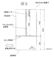
- the long ESSO test piece 4 has a test plate 6 and a run-up plate (Crac-running plate) 5 joined by a CO 2 weld 8, and the run-up plate 5 has an electrogas weld (electrogas weld) perpendicular to the CO 2 weld 8. arc weld) 7, and a brittle crack (not shown) generated from a mechanical notch 9 propagates along the electrogas weld 7 and is perpendicular to the loading direction of the test plate 6.
- the test plate 6 is rushed.
- the load direction is indicated by the arrow R. D. Rolling direction.
- the long and brittle crack propagation stop characteristic means that a long ESOP test piece 4 having a long brittle crack propagation distance before entering the test plate 6 is used, and stress reflection is similar to that in an actual ship. This refers to those evaluated by a testing machine that has a sufficiently long distance between the tab plate tips and the load load point without any influence.
- the stress reflection here refers to reflection of a compressive stress wave generated by the occurrence and propagation of a brittle crack at a tab plate of testing machine. When this stress reflection occurs, the compressive stress wave returns to the brittle crack propagation portion, so that the brittle crack tends to stop.
- the steel sheet according to the present invention preferably has a texture described below.
- the X-ray intensity ratio of the (211) plane or the (100) plane at the rolling surface in the region of at least 20% of the plate thickness at the center of the plate thickness is 1.5 or more, the plate thickness of 1/4 t to 1/10 t, or the plate
- the X-ray intensity ratio of the (110) plane at the rolling surface of thickness 3 / 4t to 9 / 10t is 1.3 or more.
- the X-ray intensity ratio of the (110) plane on the rolled surface with a thickness of 1/4 t to 1/10 t is less than 1.3, the brittleness in the region of 20% or more of the thickness of the central portion of the thickness is obtained.
- the crack stop length is not shorter than the brittle crack stop length in the region of the plate thickness from 1/4 t to 1/10 t, and is not shorter than the plate thickness by the thickness of about 1/4 t to 1/10 t (point A in FIG. 1).
- the failure driving force of the longest crack propagation part near the point A ′ does not decrease. Therefore, the X-ray intensity ratio of the (110) plane at the rolled surface having a thickness of 1/4 t to 1/10 t was limited to 1.3 or more. The same applies to the thickness 3 / 4t to 9 / 10t part.
- vTrs-12X (100) -22X (211) ⁇ (T-75) /0.64 (However, in the formula, X (211) is the (211) plane X-ray intensity ratio at the rolling surface in the region at least 20% of the plate thickness (t) at the center of the plate thickness, and X (100) is the same site (100) Plane X-ray intensity ratio, vTrs (° C.) is the fracture surface transition temperature obtained by the 2 mm V notch Charpy impact test at the same site, and T is the service temperature (° C.) of the steel sheet)
- This parameter formula defines the toughness of the steel sheet by vTrs according to the texture in order to ensure the brittle crack propagation stop toughness of the target area in the texture.
- vTrs is defined so as to satisfy the above equation.
- the X-ray intensity ratio of the (211) plane or the (100) plane needs to be 1.5 or more. Since the texture greatly contributes to the improvement of brittle crack propagation stop toughness, the coefficient of X (211) is made larger than X (100) in the equation.
- the preferable component composition and manufacturing conditions of the steel sheet having the above-described characteristics are as follows. In the description,% is mass%. [Ingredient composition] C: 0.15% or less C is necessary to ensure strength. From the viewpoint of securing strength, the lower limit is preferably 0.02%. However, if the C content exceeds 0.15%, the weld heat affected zone (HAZ) toughness decreases, so the content was limited to 0.15% or less. In order to further develop the texture of the (211) plane and the (100) plane, the preferable range is 0.03% or less. Si: 0.60% or less Si is an element effective for increasing the strength. In order to acquire the effect, it is preferable to contain 0.01% or more. If the Si content exceeds 0.60%, the weld heat affected zone (HAZ) toughness is remarkably deteriorated, so it is limited to 0.60% or less.
- Mn 0.80 to 1.80% Mn is an element effective for increasing the strength, and the lower limit is set to 0.80% from the viewpoint of securing the strength. However, if the amount of Mn exceeds 1.80%, there is a concern about deterioration of the base material toughness. Therefore, Mn is set in the range of 0.80 to 1.80%. A preferred range is 1.00 to 1.70%.
- Ti forms carbide (nitride) precipitates (precipitate)
- HAZ welded heat-affected zone
- Nb is also effective for precipitation strengthening and toughness improvement. Moreover, the recrystallization of austenite is suppressed, and the effect by the rolling conditions described later is promoted. In order to obtain these effects, addition of 0.001% or more is necessary, but if added over 0.1%, the quenched structure tends to become needle-like and the toughness tends to deteriorate. The upper limit is 1%.
- Cu 2.0% or less, V: 0.2% or less, Ni: 2.0% or less, Cr: 0.6% or less, Mo: 0.6% or less, W: 0.5% or less, B: At least one selected from 0.0050% or less and Zr: 0.5% or less Cu: 2.0% or less Cu can be used mainly for precipitation strengthening. In order to acquire the effect, it is preferable to contain 0.05% or more. If the Cu content exceeds 2.0%, precipitation strengthening becomes excessive and the toughness deteriorates. Therefore, the Cu content is preferably in the range of 2.0% or less.
- V 0.2% or less
- V is a component that can be used for solid solution strengthening and precipitation strengthening. In order to acquire the effect, it is preferable to contain 0.001% or more. If the V content exceeds 0.2%, the base metal toughness and weldability are greatly impaired. Therefore, the V content is preferably in the range of 0.2% or less.
- Ni 2.0% or less Ni is effective in improving strength and toughness and preventing Cu cracking during rolling when Cu is added. In order to acquire the effect, it is preferable to contain 0.05% or more. However, since it is expensive and its effect is saturated even if it is added excessively, it is preferably added in a range of 2.0% or less.
- Cr 0.6% or less Cr has an effect of increasing strength. In order to acquire the effect, it is preferable to contain 0.01% or more. However, if the content exceeds 0.6%, the weld zone toughness deteriorates, so the Cr content is preferably in the range of 0.6% or less.
- Mo 0.6% or less Mo has an effect of increasing the strength at normal temperature and high temperature. In order to acquire the effect, it is preferable to contain 0.01% or more. However, if the content exceeds 0.6%, the weldability deteriorates, so the content is preferably in the range of 0.6% or less.
- W 0.5% or less W has an effect of increasing the high-temperature strength. In order to acquire the effect, it is preferable to contain 0.05% or more. However, if it exceeds 0.5%, not only is the toughness deteriorated, but it is expensive, so it is preferably contained in a range of 0.5% or less.
- B 0.0050% or less B precipitates as BN during rolling, and fines ferrite grains after rolling. In order to acquire the effect, it is preferable to contain 0.0010% or more. However, if it exceeds 0.0050%, the toughness deteriorates, so it is limited to 0.0050% or less.
- Zr 0.5% or less
- Zr is an element that increases the strength and improves the plating cracking resistance of the galvanized material. In order to acquire the effect, it is preferable to contain 0.03% or more. However, since the weld toughness deteriorates if the content exceeds 0.5%, the Zr content is preferably 0.5% as an upper limit.
- the steel according to the present invention is the balance Fe and unavoidable impurities in addition to the above component composition. Inevitable impurities include P: 0.035% or less, Al: 0.08% or less, N: 0.012% or less, 0: 0.05% or less, Mg: 0.01% or less, and the like. Acceptable.
- the temperature and cooling rate are average values in the thickness direction.
- Heating temperature The steel material is heated to a temperature of 900 to 1350 ° C.
- a heating temperature of 900 ° C. or higher is necessary for homogenization of the material and controlled rolling described later, and a temperature of 1350 ° C. or lower is marked by surface oxidation when the temperature is excessively high. This is because coarsening of crystal grains is unavoidable.
- the upper limit is preferably set to 1150 ° C.
- the steel plate at the end of rolling has a one-pass rolling reduction of 7% or more and a cumulative rolling reduction of 50% or more.
- Hot rolling under the condition of a surface temperature of 850 to 550 ° C When the steel plate surface temperature is 900 to 600 ° C and the steel plate internal temperature is 50 to 150 ° C higher than the steel plate surface temperature, the surface vicinity is almost two phases.
- the steel plate and the inside of the steel sheet are substantially non-recrystallization regions.
- the basis of the (211) plane texture which is a kind of transformation texture effective for crack generation at the brittle crack tip, is formed.
- the one-pass rolling reduction rate it is more preferable to set the one-pass rolling reduction rate to 10% or more.
- a more preferable cooling start temperature is 700 ° C. or higher.
- the steel plate according to the present invention when the steel plate according to the present invention is less than 50 mm thick, it has excellent brittle crack propagation characteristics.
- FIG. 3A, 3B, and 3C show dynamic FEM analysis models, and FIG. 4 shows the results.
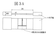
- FIG. 3A is a parametric model for determining the condition without stress reflection, and is a model for analyzing the influence of the distance (2A in FIG. 3A) between the tester tab plates 11 (thickness 200 mm) that affects the stress reflection. is there.
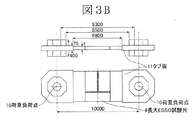
- FIG. 3B is a model when the distance of the load load point 10 of the test machine to be used is set to 10 m
- FIG. 3C is a model when the distance of the load load point 10 of the test machine to be used is set to 5 m.
- FIG. 4 shows the FEM analysis results.
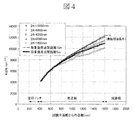
- FIG. 4 shows the change in the dynamic stress intensity factor (fracture driving force during brittle crack propagation) Kd of the crack during propagation from the occurrence of fracture to the entry into the test plate.
- FIG. 4 shows the analysis result obtained by the model when the distance between the load points of the test machine used is set to 5 m and 10 m. The large tension of the 10 m model between the load points shown in FIG. 3B is shown. If a long ESSO test is performed with the test jig shape, it is recognized that the evaluation is performed under conditions equivalent to an actual ship without stress reflection.
- the evaluation method of the long-brittle crack propagation stopping performance under conditions equivalent to an actual ship without stress reflection is the test piece length or the distance between the tab plate tips of the test apparatus to which the test piece is attached is 2 .Times.8 times or more ( ⁇ 6800 mm / 2400 mm), and further, the distance between the load points of the test apparatus was 4.1 times or more ( ⁇ 10000 mm / 2400 mm) of the test piece width.
- the distance between the tab plate tips of the test device to which the test piece is attached is 2.8 times or more of the test piece width. ( ⁇ 6800 mm / 2400 mm), and further, the distance between the load points of the test apparatus was 4.1 times or more the width of the test piece ( ⁇ 10000 mm / 2400 mm).
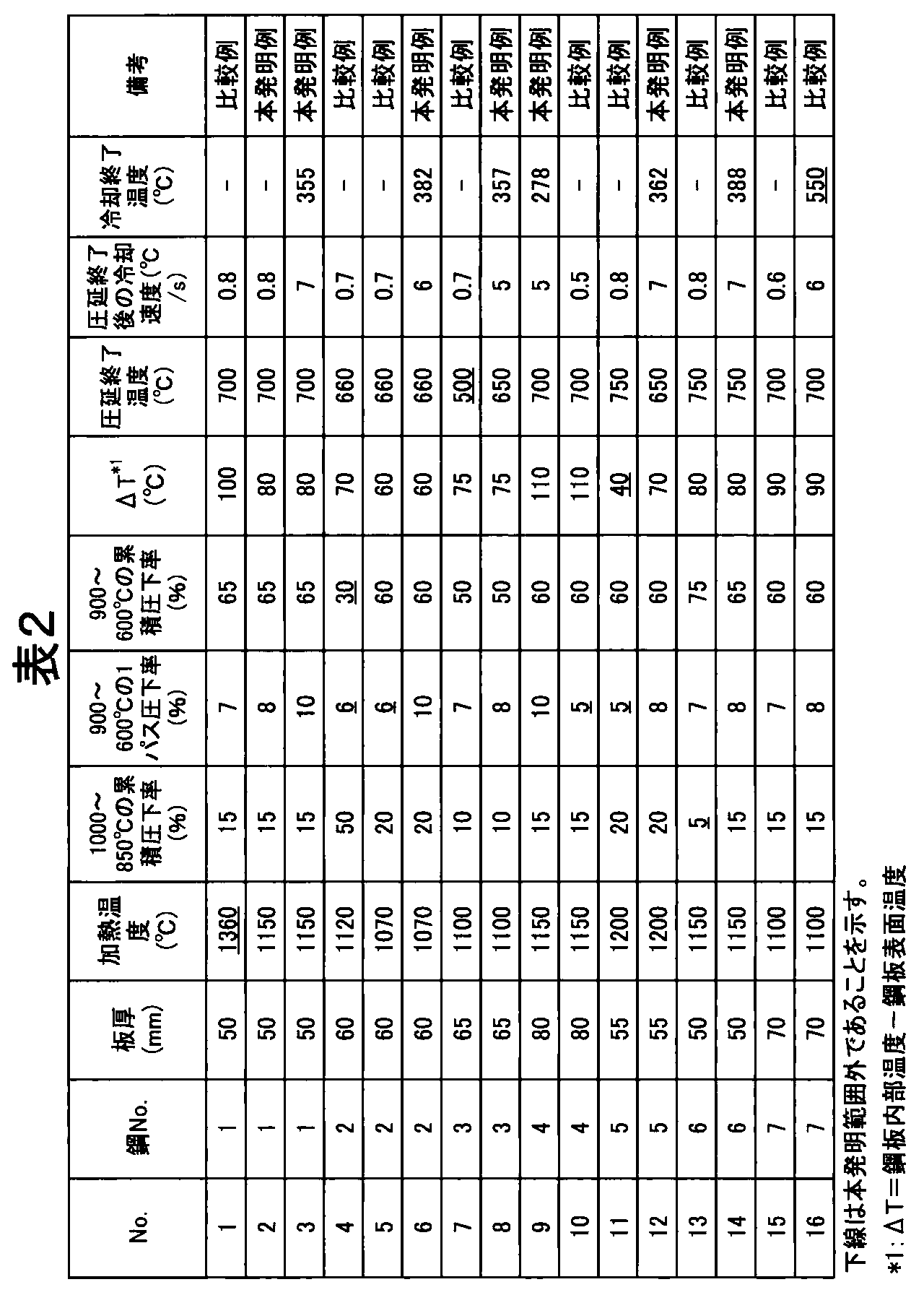
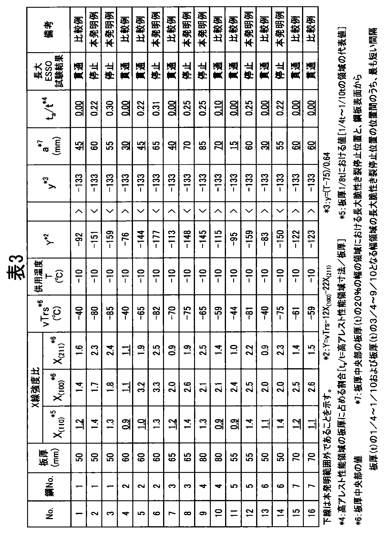
- Thick steel plates were manufactured according to the conditions shown in Table 2 using steel slabs adjusted to various chemical compositions shown in Table 1. For each thick steel plate thus obtained, the X-ray intensity ratio between the (211) plane and the (100) plane of the central portion (high arrest performance region) of the plate thickness (t) is measured, and the Charpy fracture surface transition temperature ( Ductile-Brittle transition temperature of Charimpact test) vTrs was investigated. Further, the X-ray intensity ratio of the (110) plane of 1/8 part of the plate thickness (t) (representative part in the region of 1/4 to 1/10 of the plate thickness (t)) was measured.
- a large ESSO test piece having the dimensions shown in FIG. 2 was prepared using the above-mentioned thick steel plate (the original thickness of the plate thickness (t)), and the test was performed. It was used for. The test was performed under the conditions of a stress of 257 N / mm 2 and a temperature of ⁇ 10 ° C.
- the stress 257 N / mm 2 is the maximum allowable stress of the yield strength 40 kgf / mm 2 grade steel plate frequently used in the hull, and the temperature ⁇ 10 ° C. is the design temperature of the ship.
- the long ESSO test was conducted using a large tensile test jig shown in FIG.
- Table 3B shows the results of the long ESSO test.
- examples Nos. 2, 3, 6, 8, 9, 12, 14
- the brittle cracks stopped at the fillet welds
- comparative examples No. 1, 4, 5, 7, 10, 11, In 13, 15, 16
- the brittle crack did not stop.
Landscapes
- Chemical & Material Sciences (AREA)
- Engineering & Computer Science (AREA)
- Organic Chemistry (AREA)
- Metallurgy (AREA)
- Materials Engineering (AREA)
- Mechanical Engineering (AREA)
- Physics & Mathematics (AREA)
- Thermal Sciences (AREA)
- Crystallography & Structural Chemistry (AREA)
- Analytical Chemistry (AREA)
- Pathology (AREA)
- Immunology (AREA)
- General Physics & Mathematics (AREA)
- General Health & Medical Sciences (AREA)
- Biochemistry (AREA)
- Life Sciences & Earth Sciences (AREA)
- Health & Medical Sciences (AREA)
- Heat Treatment Of Steel (AREA)
- Investigating Strength Of Materials By Application Of Mechanical Stress (AREA)
Abstract
長大脆性き裂停止部の先端形状で、板厚中央部の板厚の20%の領域が、鋼板表面から板厚の1/4~1/10となる領域に対し、少なくとも板厚分の長さだけ長大脆性き裂の進行方向に対し凹陥部を形成し、板厚中央部で少なくとも板厚の20%の領域の圧延面での(211)面もしくは(100)面のX線強度比が1.5以上、板厚の1/4~1/10の領域または板厚の3/4~9/10の圧延面での(110)面のX線強度比が1.3以上の厚鋼板、特定成分の鋼を900~1350℃に加熱後、鋼板表面温度1000~850℃、累積圧下率10%以上で圧延後、特定の表面温度と内部温度の状態で、1パス圧下率7%以上、累積圧下率50%以上で圧延終了時の鋼板表面温度800~550℃で熱間圧延する厚鋼板の製造方法、及び長大脆性き裂に対する伝播停止性能の評価方法並びに評価装置を提供する。
Description
本発明は、大型コンテナ船(Mega−container carrier)やバルクキャリアー(bulk carrier)などに用いて好適な脆性き裂伝播停止特性(brittle crack arrestability)に優れる板厚50mm以上の厚鋼板およびその製造方法に関する。また、実船相当の長大脆性き裂伝播停止性能を評価する方法ならびに試験装置に関する。
コンテナ船やバルクキャリアーは、積載能力(carrying capacity)の向上や荷役効率(cargo handling efficiency)の向上等のため、上部開口部(upper aperture)を大きくとった構造となっている。このため、船体の剛性(rigidity)および縦強度(longitudinal strength)を確保するために、これらの船では特に船体外板(outer plate of vessel’s body)を厚肉化する必要がある。
近年、コンテナ船は大型化し、6、000~20、000TEU(twenty−foot equivalent unit)の大型船では船体外板の板厚は50mm以上となり、板厚効果(Thickness effect)により破壊靱性(fracture toughness)が低下することに加え、溶接入熱(welding heat input)もより大きくなるため、溶接部(welded part)の破壊靭性が一層低下する傾向にある。なお、TEU(Twenty−foot Equivalent Unit)は、長さ20フィートのコンテナに換算した個数を表し、コンテナ船の積載能力の指標を示している。
船舶(ships)やラインパイプ(linepipe)に使用される鋼板の板厚が50mm未満の比較的薄手の鋼材に対しては、TMCP法(Thermomechanical controlled processing)により細粒化を図り、低温靭性(low−temperature toughness)を向上させて、優れた脆性き裂伝播停止特性を付与することができる。
合金コスト(alloy cost)を上昇させることなく、鋼材の表層部(surface part)の組織を超微細化する技術が、脆性き裂伝播停止特性を向上させる手段として提案されている。例えば、特許文献1では、脆性き裂が伝播する際に、鋼材表層部に発生するシアリップ(shear−lips)(塑性変形領域(plastic deformation area))が脆性き裂伝播停止特性の向上に効果があることに着目し、シアリップ部分の結晶粒を微細化させて、伝播する脆性き裂が有する伝播エネルギー(propagation energy)を吸収させる方法が開示されている。
鋼板を熱間圧延後、制御冷却(controlled cooling)により表層部分をAr3変態点以下に冷却し、その後制御冷却を停止して表層部分を変態点以上に復熱させる工程を1回以上繰り返して行い、この間に鋼材に圧下を加えることにより、繰り返し変態させ又は加工再結晶(recrystallization due to deformation)させて、表層部分に超微細なフェライト組織(ferrite structure)又はベイナイト組織(bainite structure)を生成させるものである。
特許文献2には、フェライト−パーライト(pearlite)を主体のミクロ組織(microstructure)とする鋼材において両表面部を円相当平均粒径:5μm以下、アスペクト比(aspect ratio):2以上のフェライト粒を有するフェライト組織を50%以上有する層で構成し、更に仕上げ圧延中の1パス当りの最大圧下率(maximum rolling reduction)を12%以下にすることで局所的な再結晶現象(recrystallization phenomenon)を抑制し、フェライト粒径のバラツキを抑えると優れた脆性き裂伝播停止特性向上の得られることが開示されている。
特許文献3には、塑性変形(plastic deformation)を受けた後の耐脆性き裂伝播特性に優れた鋼材として、以下の(a)~(d)に述べる方法によって製造される結晶粒内にサブグレイン(sub−grain)を形成させた微細フェライトを主組織とする鋼材が開示されている。
(a)微細なフェライト結晶粒を確保する圧延条件、(b)鋼材板厚の5%以上の部分に微細フェライト組織を生成させる圧延条件、(c)微細フェライトに集合組織を発達させるとともに加工(圧延)により導入した転位(dislocation)を熱的エネルギー(thermal energy)により再配置しサブグレインを形成させる圧延条件、(d)形成した微細なフェライト結晶粒と微細なサブグレイン粒の粗大化を抑制する冷却条件、によって、鋼板表層の冷却および復熱などの複雑な温度制御(temperature control)を必要とせずに、塑性変形を受けた後の脆性き裂伝播停止特性を向上させる。
また、特許文献1~3と異なる技術思想(technological thought)として特許文献4には、集合組織(texture)を発達させることにより、鋼材の破壊面上にセパレーションを板厚方向と平行な方向に発生させ、脆性き裂先端(brittle crack tip)の応力を緩和させることにより、耐脆性き裂伝播特性を高める方法において、制御圧延により(110)面X線強度比(X−ray intensity ratio)を2以上とし、かつ円相当径20μm以上の粗大粒を10%以下とすることが記載されている。
特許文献5では溶接継手部(welded joint)の脆性き裂伝播停止性能の優れた溶接構造用鋼として、板厚内部においての圧延面での(100)面のX線面強度比が1.5以上を有することを特徴とする鋼板が開示され、集合組織発達により、応力負荷方向(stress loading direction)に垂直な方向に対して、き裂伝播方向(crack propagation direction)を変化させて、脆性き裂を溶接継手部から母材側に誘導し、継手としての脆性き裂伝播停止性能を向上させることが記載されている。
また、特許文献6には、板厚中央部における圧延面での(211)面のX線強度比が1.3以上、かつ板厚1/4部における圧延面での(100)面X線強度比が1.5以上、板表層部における圧延面での(100)面X線強度比が1.5以上を有することを特徴とする鋼板が開示され、集合組織発達により、T継手等を介し鋼板表面から突入する脆性き裂先端近傍にクラック(crack)が発生し、そのクラックがき裂伝播抵抗として作用し板厚方向に伝播する脆性き裂に対する脆性き裂伝播停止性能が向上することが記載されている。
一方、船体構造(hull structure)においては、万一溶接部から脆性破壊(brittle failure)が発生した場合にも、脆性き裂の伝播を停止させ船体分離を防止することが必要と考えられている。板厚50mm未満の造船用鋼板溶接部の脆性き裂伝播挙動については、日本造船研究協会(The Shipbuilding Research Association of Japan)第147委員会において、実験的に検討がなされている。
第147委員会では、溶接部にて強制的に発生させた脆性き裂の伝播経路、伝播挙動を実験的に調査した結果、溶接部の破壊靱性(fracture toughness)がある程度確保されていれば、溶接残留応力(welding residual stress)の影響により脆性き裂は溶接部から母材側に逸れてしまうことが多いが、溶接部に沿って脆性き裂が伝播した例も複数確認された。このことは、脆性破壊が溶接部に沿って直進伝播する可能性が無いとは言い切れないことを示唆している。
しかしながら、第147委員会で適用した溶接と同等の溶接を板厚50mm未満の鋼板に適用して建造された船舶が何ら問題なく就航(actual service)しているという多くの実績があることに加え、靱性が良好な鋼板母材(造船E級鋼など)は脆性き裂を停止する能力が十分にあるとの認識から、造船用鋼材溶接部の脆性き裂伝播停止特性は船級規則(Rules and Guidance for the survey and construction of steel ships)等には要求されてこなかった。
山口ら:「超大型コンテナ船(Mega−container carrier)の開発—新しい高強度極厚鋼板(new high strength heavy gauge steel plate)の実用—」、日本船舶海洋工学会誌、3、(2005)、P70.
しかしながら、最近の6、000TEUを超える大型コンテナ船では鋼板の板厚は50mmを超え、板厚効果により破壊靱性が低下することに加え、溶接入熱もより大きくなるため、溶接部の破壊靭性が一層低下する傾向にある。
最近、このような厚肉大入熱溶接継手(large heat input welded joint of heavy gauge steel plate)では、溶接部から発生した脆性き裂は母材側に逸れずに直進し長大化(long and large)し、骨材(あるいは、補強材ともいう。stiffeners)等の鋼板母材部でも停止しないことが実験的に示され(非特許文献1)、50mm以上の板厚の鋼板を適用した船体構造の安全確保の上で大きな問題となっている。また、このような船体の安全性確保を評価する試験として、長大ESSO試験があるが、評価方法の相違や試験装置の制約などにより試験結果が変化し、必ずしも実船に相当する長大脆性き裂伝播停止性能が評価されていないという問題があった。
上述した特許文献1~6記載の鋼板は長大化した脆性き裂伝播停止特性について記載がなく、非特許文献1で明らかにされた課題を解決することができない。また、実船相当の長大脆性き裂伝播停止特性を評価する方法や試験装置については、特許文献1~6記載の技術には記載がなく、実船相当の安全性評価という課題を解決することができない。
そこで、本発明は、50mm以上の板厚の鋼板およびその溶接部において、脆性破壊が発生した場合でも、大規模破壊(catastrophic fracture)に至る前に長大化した脆性き裂を停止させる厚鋼板およびその製造方法を提供することを目的とする。加えて、実船相当の長大脆性き裂伝播停止性能を評価する方法ならびに試験装置を提供することを目的とする。なお、ここでいう長大脆性き裂とは、隣接する他の鋼板から突入する長さ1m以上の脆性き裂のことである。
本発明者らは、化学組成および圧延条件を変化させた多くの鋼板について集合組織形態と脆性き裂伝播停止特性(アレスト性能(arrestability)という場合がある)の関係を調査するとともに、長大脆性き裂伝播停止現象に及ぼすアレスト性能(靭性や集合組織に影響される)の板厚方向の分布の影響を調査した。また、タブ板先端間距離(distance between tips of tab plates)もしくは荷重負荷点間距離(distance between loading points)を変化させた動的FEM解析により、実船相当の長大脆性き裂伝播特性を模擬できる長大ESSO試験の評価方法、試験装置について検討した。
その結果、化学組成および圧延条件を制御し、アレスト性能に影響を与える靭性および集合組織の板厚方向の分布を規定した場合、長大脆性き裂伝播停止性能が飛躍的に向上し、これまで停止が困難と考えられてきた厚物鋼板もしくはその溶接部を伝播してきた長大脆性き裂を応力反射の無い実船相当条件下において、鋼板にて停止させうることを知見した。さらに、動的FEM解析の結果、タブ板先端間距離および荷重負荷点間距離を所定の値とすることで、応力反射の無い実船に相当する長大ESSO試験の評価方法、試験装置について知見した。なお、厚さ50mm未満の厚鋼板は、現行鋼板(例えば造船用E級鋼など)で長大脆性き裂を停止させることができるため、本発明は厚さ50mm以上の厚鋼板を対象とした。
本発明は上記知見を基に更に検討を加えてなされたもので、すなわち本発明は、
(1)板厚(t)が50mm以上の厚鋼板であって、板厚方向断面における長大脆性き裂伝播停止部の先端形状において、板厚中央部の板厚(t)の20%の幅の領域における停止き裂長さが、鋼板表面から板厚(t)の1/4~1/10または板厚(t)の3/4~9/10となる領域の最大き裂長さに対し、少なくとも板厚(t)の長さだけ前記長大脆性き裂の進行方向に対し短く、凹んだ凹陥部を形成していることを特徴とする長大脆性き裂伝播停止特性に優れる板厚(t)が50mm以上の厚鋼板。
(2)前記板厚中央部で板厚(t)の少なくとも20%の領域における部位の圧延面での(211)面もしくは(100)面のX線強度比が1.5以上、前記板厚(t)の1/4~1/10となる領域または前記板厚(t)の3/4~9/10となる領域の圧延面での(110)面のX線強度比が1.3以上であることを特徴とする、(1)記載の長大脆性き裂伝播停止特性に優れる板厚(t)が50mm以上の厚鋼板。
(3)前記板厚中央部で板厚(t)の少なくとも20%の領域における部位の圧延面での(211)面X線強度比X(211)と(100)面X線強度比X(100)および同部位の2mmVノッチシャルピー衝撃試験により得られる破面遷移温度vTrs(℃)が式:vTrs−12X(100)−22X(211)≦(T−75)/0.64[Tは鋼板の供用温度(℃)]を満足し、且つ前記板厚(t)の1/4~1/10となる領域または前記板厚(t)の3/4~9/10となる領域の圧延面での(110)面のX線強度比が1.3以上であることを特徴とする、(1)または(2)に記載の長大脆性き裂伝播停止特性に優れる板厚(t)が50mm以上の厚鋼板。
(4)鋼組成が、質量%で、C:0.15%以下、Si:0.60%以下、Mn:0.80~1.80%、S:0.001~0.05%を含み、Ti:0.005~0.050%またはNb:0.001~0.1%の内から選んだ少なくとも1種を含み、更に、Cu:2.0%以下、V:0.2%以下、Ni:2.0%以下、Cr:0.6%以下、Mo:0.6%以下、W:0.5%以下、B:0.0050%以下、Zr:0.5%以下の内から選んだ少なくとも1種を含有し、残部Feおよび不可避的不純物からなることを特徴とする(1)乃至(3)のいずれか一つに記載の長大脆性き裂伝播停止特性に優れる板厚(t)が50mm以上の厚鋼板。
(5)(4)に記載の成分組成を有する鋼素材を、900~1350℃の温度に加熱し、次いで鋼板表面温度1000~850℃の温度域において累積圧下率10%以上圧延した後、鋼板表面温度900~600℃且つ鋼板内部温度が鋼板表面温度より50~150℃高温となる状態とし、その後、1パス圧下率7%以上、累積圧下率50%以上で、圧延終了時の鋼板表面温度800~550℃で熱間圧延することを特徴とする長大脆性き裂伝播停止特性に優れる板厚(t)が50mm以上の厚鋼板の製造方法。
(6)更に、熱間圧延を終了した後、5℃/s以上の冷却速度で400℃まで冷却することを特徴とする(5)記載の長大脆性き裂伝播停止特性に優れる板厚(t)が50mm以上の厚鋼板の製造方法。
(7)
試験片幅2m以上の大型試験片を用いて、き裂伝播長1m以上の長大脆性き裂に対する伝播停止性能を評価・確認する試験において、試験片長さもしくは試験片を取り付ける試験装置のタブ板先端間距離が試験片幅の2.8倍以上であることを特徴とする、鋼材もしくは構造物の長大脆性き裂伝播停止性能の評価方法
(8)
(7)に記載の評価方法において、さらに、試験装置の荷重負荷点間距離が試験片幅の4.1倍以上であることを特徴とする鋼材もしくは構造物の長大脆性き裂伝播停止性能の評価方法
(9)
試験片幅2m以上の大型試験片を用いて、き裂伝播長1m以上の長大脆性き裂に対する伝播停止性能を評価・確認する試験装置において、試験片を取り付ける試験装置のタブ板先端間距離が試験片幅の2.8倍以上であることを特徴とする、長大脆性き裂伝播停止性能を評価する試験装置
(10)
(9)に記載の試験装置において、さらに、試験装置の荷重負荷点間距離が試験片幅の4.1倍以上であることを特徴とする長大脆性き裂伝播停止性能を評価する試験装置
(1)板厚(t)が50mm以上の厚鋼板であって、板厚方向断面における長大脆性き裂伝播停止部の先端形状において、板厚中央部の板厚(t)の20%の幅の領域における停止き裂長さが、鋼板表面から板厚(t)の1/4~1/10または板厚(t)の3/4~9/10となる領域の最大き裂長さに対し、少なくとも板厚(t)の長さだけ前記長大脆性き裂の進行方向に対し短く、凹んだ凹陥部を形成していることを特徴とする長大脆性き裂伝播停止特性に優れる板厚(t)が50mm以上の厚鋼板。
(2)前記板厚中央部で板厚(t)の少なくとも20%の領域における部位の圧延面での(211)面もしくは(100)面のX線強度比が1.5以上、前記板厚(t)の1/4~1/10となる領域または前記板厚(t)の3/4~9/10となる領域の圧延面での(110)面のX線強度比が1.3以上であることを特徴とする、(1)記載の長大脆性き裂伝播停止特性に優れる板厚(t)が50mm以上の厚鋼板。
(3)前記板厚中央部で板厚(t)の少なくとも20%の領域における部位の圧延面での(211)面X線強度比X(211)と(100)面X線強度比X(100)および同部位の2mmVノッチシャルピー衝撃試験により得られる破面遷移温度vTrs(℃)が式:vTrs−12X(100)−22X(211)≦(T−75)/0.64[Tは鋼板の供用温度(℃)]を満足し、且つ前記板厚(t)の1/4~1/10となる領域または前記板厚(t)の3/4~9/10となる領域の圧延面での(110)面のX線強度比が1.3以上であることを特徴とする、(1)または(2)に記載の長大脆性き裂伝播停止特性に優れる板厚(t)が50mm以上の厚鋼板。
(4)鋼組成が、質量%で、C:0.15%以下、Si:0.60%以下、Mn:0.80~1.80%、S:0.001~0.05%を含み、Ti:0.005~0.050%またはNb:0.001~0.1%の内から選んだ少なくとも1種を含み、更に、Cu:2.0%以下、V:0.2%以下、Ni:2.0%以下、Cr:0.6%以下、Mo:0.6%以下、W:0.5%以下、B:0.0050%以下、Zr:0.5%以下の内から選んだ少なくとも1種を含有し、残部Feおよび不可避的不純物からなることを特徴とする(1)乃至(3)のいずれか一つに記載の長大脆性き裂伝播停止特性に優れる板厚(t)が50mm以上の厚鋼板。
(5)(4)に記載の成分組成を有する鋼素材を、900~1350℃の温度に加熱し、次いで鋼板表面温度1000~850℃の温度域において累積圧下率10%以上圧延した後、鋼板表面温度900~600℃且つ鋼板内部温度が鋼板表面温度より50~150℃高温となる状態とし、その後、1パス圧下率7%以上、累積圧下率50%以上で、圧延終了時の鋼板表面温度800~550℃で熱間圧延することを特徴とする長大脆性き裂伝播停止特性に優れる板厚(t)が50mm以上の厚鋼板の製造方法。
(6)更に、熱間圧延を終了した後、5℃/s以上の冷却速度で400℃まで冷却することを特徴とする(5)記載の長大脆性き裂伝播停止特性に優れる板厚(t)が50mm以上の厚鋼板の製造方法。
(7)
試験片幅2m以上の大型試験片を用いて、き裂伝播長1m以上の長大脆性き裂に対する伝播停止性能を評価・確認する試験において、試験片長さもしくは試験片を取り付ける試験装置のタブ板先端間距離が試験片幅の2.8倍以上であることを特徴とする、鋼材もしくは構造物の長大脆性き裂伝播停止性能の評価方法
(8)
(7)に記載の評価方法において、さらに、試験装置の荷重負荷点間距離が試験片幅の4.1倍以上であることを特徴とする鋼材もしくは構造物の長大脆性き裂伝播停止性能の評価方法
(9)
試験片幅2m以上の大型試験片を用いて、き裂伝播長1m以上の長大脆性き裂に対する伝播停止性能を評価・確認する試験装置において、試験片を取り付ける試験装置のタブ板先端間距離が試験片幅の2.8倍以上であることを特徴とする、長大脆性き裂伝播停止性能を評価する試験装置
(10)
(9)に記載の試験装置において、さらに、試験装置の荷重負荷点間距離が試験片幅の4.1倍以上であることを特徴とする長大脆性き裂伝播停止性能を評価する試験装置
本発明によれば、板厚(t)が50mm以上の厚鋼板において優れた脆性き裂伝播停止性能を付与することが可能で、これまで困難であった板厚50mm以上の厚物材における長大脆性き裂を応力反射(stress reflection)の無い実船相当条件下において停止させることができ産業上極めて有用である。
本発明では、板厚方向断面における長大脆性き裂伝播停止部の先端形状を規定する。以下に本発明の限定理由について説明する。
図1に本発明に係る板厚(t)が50mm以上の鋼板1の板厚方向断面における長大脆性き裂2の伝播停止部の先端形状(長大脆性き裂停止位置3)を模式的に示す。
本発明では、長大脆性き裂伝播停止部の先端形状を、板厚中央部の板厚(t)の20%の幅の領域における長大脆性き裂停止位置と、鋼板表面から板厚(t)の1/4~1/10および板厚(t)の3/4~9/10となる幅領域の長大脆性き裂停止位置の位置間のうち、最も短い間隔(以下、深さa)が少なくとも板厚(t)の長さの、深さaだけ長大脆性き裂の進行方向に対し短く、凹んだ略U字状の凹陥部を有する形状とする。
鋼板全体のアレスト性能を向上させるため鋼板の板厚方向断面の板厚中央部において板厚(t)の少なくとも20%の幅の領域,ta(板厚(t)の1/2位置を含んだ、その上下10%以上の幅の領域)のアレスト性能を向上させる。なお、アレスト性能を向上させる領域,taは、圧延負荷(rolling load)の制約から50%以下とすることが好ましい。
アレスト性能を向上させた板厚中央付近の領域幅,taが板厚の20%未満となると、板厚(t)の1/4~1/10部近傍(板厚(t)の1/4位置と1/10位置を含み、1/4位置と1/10位置の間の領域)および板厚(t)の3/4~9/10部近傍(板厚(t)の3/4位置と9/10位置を含み、3/4位置と9/10位置の間の領域)の破壊駆動力が十分に下がらず、板厚(t)の1/4~1/10部近傍および板厚(t)の3/4~9/10部近傍において、き裂が停止せず伝播してしまうため、少なくとも20%とする。
板厚方向断面において他の領域よりアレスト性能に優れる領域は長大脆性き裂の停止長さが短くその進行方向に対し、凹んだ凹陥部を形成するので、長大脆性き裂伝播停止部の先端形状を板厚中央部の板厚(t)の少なくとも20%の領域を長大脆性き裂の進行方向に対して凹んだ略U字状の凹陥部とする。
また、略U字状の凹陥部の形状は、板厚(t)の1/4~1/10近傍および板厚(t)の3/4~9/10近傍の破壊駆動力の低下には、板厚中央部の板厚の20%の領域における脆性き裂停止長さが、板厚(t)の1/4~1/10および板厚(t)の3/4~9/10の領域における脆性き裂停止長さより、少なくとも板厚(t)の長さだけ短くなることが必要なため、長大脆性き裂の進行方向に対し、凹陥部の深さaが少なくとも板厚(t)の長さと等しい凹んだ形状とする。
深さaは図1中の板厚(t)の1/4~1/10および板厚(t)の3/4~9/10となる領域での長大脆性き裂停止位置(最大き裂長さとも言う)を示す板厚方向に直角な線と、板厚中央部において板厚の20%の領域幅を示す板厚方向に平行な線と長大脆性き裂伝播停止位置との交点を通る板厚方向に直角な線との間隔の内、もっとも短い間隔の長さと規定する。
厚さ50mm以上の厚鋼板の脆性破壊破面では板厚(t)の1/4~1/10または板厚(t)の3/4~9/10の領域内に最長き裂伝播部(図1のA点およびA’点付近)が観察されるため、板厚中央部近傍とこれら領域との比較において長大脆性き裂伝播停止位置が板厚方向に描く形状を本発明では規定する。なお、板厚(t)の1/2位置に対し、上下対称となる鋼板表面から板厚方向に板厚(t)の1/4~1/10の領域と板厚(t)の3/4~9/10の領域はアレスト性能、長大脆性き裂伝播停止部の先端形状が概略等しい。
上述した長大脆性き裂伝播停止部の先端形状は、図2に示す長大ESSO試験片4の破面で確認することができる。長大ESSO試験片4は、試験板6と助走板(Crack−running plate)5はCO2溶接部8で接合され、助走板5にはCO2溶接部8と直角方向にエレクトロガス溶接部(electrogas arc weld)7を設け、機械ノッチ(mechanical notch)9から発生した脆性き裂(図示しない)がエレクトロガス溶接部7に沿って伝播し、試験板6の荷重負荷方向(loading direction)と直角に試験板6に突入する。荷重負荷方向は図中矢印R.D.の圧延方向(rolling direction)とする。本発明において長大脆性き裂伝播停止特性とは、試験板6へ突入するまでの脆性き裂の伝播距離(propagation length)が長い長大ESSO試験片4を用いて、実際の船舶と同様応力反射の影響の無いタブ板先端間距離や荷重負荷点間距離の十分長い試験機により評価されるものを指す。ここでいう応力反射とは、脆性き裂が発生・伝播することにより生じる圧縮応力波(compressive stress wave)の試験機タブ板部(tab plate of testing machine)等での反射のことである。この応力反射が発生すると、圧縮の応力波が脆性き裂伝播部に戻ってくるため、脆性き裂は停止しやすくなる。実際の船舶等の構造物においては、構造物の大きさが脆性き裂に対して十分に大きいため応力反射は発生しない(あるいはしにくい)。このため、長大脆性き裂の伝播停止特性は、タブ板先端間距離や荷重負荷点間距離の十分長い試験機により評価する必要がある。
本発明に係る鋼板は以下に述べる集合組織を備えることが望ましい。
板厚中央部の板厚の少なくとも20%の領域における圧延面での(211)面もしくは(100)面のX線強度比が1.5以上、板厚1/4t~1/10t部または板厚3/4t~9/10t部の圧延面での(110)面のX線強度比が1.3以上
板厚中央付近における圧延面での(211)面もしくは(100)面のX線強度比が1.5以上になると、微細なサブクラック(subcrack)が発生し、脆性き裂伝播面(brittle crack propagating surface)の凹凸が大きくなり、き裂伝播抵抗(crack propagation resistance)が増し、脆性き裂伝播停止靭性が大きく向上する。X線強度比が1.5未満ではこの効果は認められない。以上より、板厚中央部の板厚の20%以上の領域における圧延面での(211)面もしくは(100)面のX線強度比を1.5以上に限定した。
板厚中央部の板厚の少なくとも20%の領域における圧延面での(211)面もしくは(100)面のX線強度比が1.5以上、板厚1/4t~1/10t部または板厚3/4t~9/10t部の圧延面での(110)面のX線強度比が1.3以上
板厚中央付近における圧延面での(211)面もしくは(100)面のX線強度比が1.5以上になると、微細なサブクラック(subcrack)が発生し、脆性き裂伝播面(brittle crack propagating surface)の凹凸が大きくなり、き裂伝播抵抗(crack propagation resistance)が増し、脆性き裂伝播停止靭性が大きく向上する。X線強度比が1.5未満ではこの効果は認められない。以上より、板厚中央部の板厚の20%以上の領域における圧延面での(211)面もしくは(100)面のX線強度比を1.5以上に限定した。
一方、板厚1/4t~1/10t部の圧延面での(110)面のX線強度比が1.3未満となると、板厚中央部の板厚の20%以上の領域における脆性き裂停止長さが、板厚1/4t~1/10tの領域における脆性き裂停止長さより、板厚分以上短くならず、板厚1/4t~1/10t部近傍(図1のA点およびA’点付近の最長き裂伝播部)の破壊駆動力の低下が起こらなくなる。よって、板厚1/4t~1/10t部の圧延面での(110)面のX線強度比を1.3以上に限定した。上記規定は板厚3/4t~9/10t部も同様とする。
更に、鋼板の供用温度における脆性き裂伝播停止靭性を向上させるため、下式を満足さすることが好ましい。
vTrs−12X(100)−22X(211)≦(T−75)/0.64
(但し、式においてX(211)は板厚中央部で板厚(t)の少なくとも20%の領域における部位の圧延面での(211)面X線強度比、X(100)は同部位の(100)面X線強度比、vTrs(℃)は同部位の2mmVノッチシャルピー衝撃試験により得られる破面遷移温度、Tは鋼板の供用温度(℃)を示す)
本パラメータ式は、集合組織における対象部位の脆性き裂伝播停止靭性を供用温度にて確保するため、鋼板の靭性を集合組織に応じてvTrsで規定するもので、供用温度より当該対象部位のシャルピー破面遷移温度vTrsを低温とするため、vTrsを、上式を満足するように規定する。尚、上述したように脆性き裂伝播停止靭性向上のためには、(211)面または(100)面のX線強度比1.5以上を必要とするが、両者のうち、(211)面集合組織が脆性き裂伝播停止靭性向上への寄与が大きいため、式においてX(100)に対してX(211)の係数を大きくしている。
vTrs−12X(100)−22X(211)≦(T−75)/0.64
(但し、式においてX(211)は板厚中央部で板厚(t)の少なくとも20%の領域における部位の圧延面での(211)面X線強度比、X(100)は同部位の(100)面X線強度比、vTrs(℃)は同部位の2mmVノッチシャルピー衝撃試験により得られる破面遷移温度、Tは鋼板の供用温度(℃)を示す)
本パラメータ式は、集合組織における対象部位の脆性き裂伝播停止靭性を供用温度にて確保するため、鋼板の靭性を集合組織に応じてvTrsで規定するもので、供用温度より当該対象部位のシャルピー破面遷移温度vTrsを低温とするため、vTrsを、上式を満足するように規定する。尚、上述したように脆性き裂伝播停止靭性向上のためには、(211)面または(100)面のX線強度比1.5以上を必要とするが、両者のうち、(211)面集合組織が脆性き裂伝播停止靭性向上への寄与が大きいため、式においてX(100)に対してX(211)の係数を大きくしている。
上述した特性を有する鋼板の好ましい成分組成と製造条件は以下のようである。説明において%は質量%とする。
[成分組成]
C:0.15%以下
Cは強度を確保するために必要である。強度確保の観点から望ましくは下限を0.02%とする。しかし、C量が、0.15%を超えると溶接熱影響部(HAZ)靭性が低下するので、0.15%以下に限定した。なお、(211)面および(100)面の集合組織をより一層発達させるために好ましい範囲は0.03%以下である。
Si:0.60%以下
Siは強度上昇に有効な元素である。その効果を得るには、0.01%以上含有するのが好ましい。Si量が、0.60%を超えると溶接熱影響部(HAZ)靭性を著しく劣化させるので、0.60%以下に限定した。
[成分組成]
C:0.15%以下
Cは強度を確保するために必要である。強度確保の観点から望ましくは下限を0.02%とする。しかし、C量が、0.15%を超えると溶接熱影響部(HAZ)靭性が低下するので、0.15%以下に限定した。なお、(211)面および(100)面の集合組織をより一層発達させるために好ましい範囲は0.03%以下である。
Si:0.60%以下
Siは強度上昇に有効な元素である。その効果を得るには、0.01%以上含有するのが好ましい。Si量が、0.60%を超えると溶接熱影響部(HAZ)靭性を著しく劣化させるので、0.60%以下に限定した。
Mn:0.80~1.80%
Mnは高強度化に有効な元素であり、強度確保の観点から下限を0.80%とした。しかし、Mn量が1.80%を超えると、母材靭性の劣化が懸念される。このため、Mnは0.80~1.80%の範囲とした。なお、好ましい範囲は1.00~1.70%である。
Mnは高強度化に有効な元素であり、強度確保の観点から下限を0.80%とした。しかし、Mn量が1.80%を超えると、母材靭性の劣化が懸念される。このため、Mnは0.80~1.80%の範囲とした。なお、好ましい範囲は1.00~1.70%である。
S:0.001~0.05%以下
本発明においては、脆性き裂前縁(leading edge of brittle crack)にクラック(鋼板表面に平行な割れ)を発生させる必要があるため、Sの0.001%以上の含有が必要である。しかし、Sは非金属介在物を形成し延性・靭性を劣化させるため、0.05%以下に制限した。
本発明においては、脆性き裂前縁(leading edge of brittle crack)にクラック(鋼板表面に平行な割れ)を発生させる必要があるため、Sの0.001%以上の含有が必要である。しかし、Sは非金属介在物を形成し延性・靭性を劣化させるため、0.05%以下に制限した。
Ti:0.005~0.050%、Nb:0.001~0.1%の1種または2種
Tiは、炭化物(carbide)や窒化物(nitride)の析出物(precipitate)を形成することにより、鋼板製造時の加熱段階でのオーステナイト粒(austenite grain)の成長を抑制して細粒化に寄与するとともに、溶接熱影響部(welded heat−affected zone)(HAZ)の結晶粒粗大化も抑制しHAZ靱性を向上する効果がある。これらの効果を得るには、0.005%以上の含有が必要である。一方、過度の含有は、靱性を劣化するため、0.050%を上限とする。
Tiは、炭化物(carbide)や窒化物(nitride)の析出物(precipitate)を形成することにより、鋼板製造時の加熱段階でのオーステナイト粒(austenite grain)の成長を抑制して細粒化に寄与するとともに、溶接熱影響部(welded heat−affected zone)(HAZ)の結晶粒粗大化も抑制しHAZ靱性を向上する効果がある。これらの効果を得るには、0.005%以上の含有が必要である。一方、過度の含有は、靱性を劣化するため、0.050%を上限とする。
Nbは析出強化(precipitation strengthening)および靱性の向上にも有効である。また、オーステナイトの再結晶(recrystallization)を抑制し、後述する圧延条件による効果を促進する。これらの効果を得るためには、0.001%以上の添加が必要であるが、0.1%を超えて添加すると、焼き入れ組織が針状化して靱性が劣化する傾向にあるため、0.1%を上限とする。
Cu:2.0%以下、V:0.2%以下、Ni:2.0%以下、Cr:0.6%以下、Mo:0.6%以下、W:0.5%以下、B:0.0050%以下、Zr:0.5%以下の内から選んだ少なくとも1種
Cu:2.0%以下
Cuは、主として析出強化のために用いることができる。その効果を得るには、0.05%以上含有するのが好ましい。Cu量が、2.0%をこえて添加すると、析出強化が過多となり靱性が劣化するので、2.0%以下の範囲とすることが好ましい。
Cu:2.0%以下
Cuは、主として析出強化のために用いることができる。その効果を得るには、0.05%以上含有するのが好ましい。Cu量が、2.0%をこえて添加すると、析出強化が過多となり靱性が劣化するので、2.0%以下の範囲とすることが好ましい。
V:0.2%以下
Vは固溶強化(solid solution strengthening)と析出強化が利用できる成分である。その効果を得るには、0.001%以上含有するのが好ましい。V量が、0.2%を超えて含有すると、母材靭性および溶接性を大きく損なうので、0.2%以下の範囲とすることが好ましい。
Vは固溶強化(solid solution strengthening)と析出強化が利用できる成分である。その効果を得るには、0.001%以上含有するのが好ましい。V量が、0.2%を超えて含有すると、母材靭性および溶接性を大きく損なうので、0.2%以下の範囲とすることが好ましい。
Ni:2.0%以下
Niは、強度および靱性を向上し、またCuを添加した場合には圧延時のCu割れを防止するのに有効である。その効果を得るには、0.05%以上含有するのが好ましい。しかし、高価である上、過剰に添加してもその効果が飽和するため、2.0%以下の範囲で添加することが好ましい。
Niは、強度および靱性を向上し、またCuを添加した場合には圧延時のCu割れを防止するのに有効である。その効果を得るには、0.05%以上含有するのが好ましい。しかし、高価である上、過剰に添加してもその効果が飽和するため、2.0%以下の範囲で添加することが好ましい。
Cr:0.6%以下
Crは、強度を上昇させる効果を有する。その効果を得るには、0.01%以上含有するのが好ましい。しかし、0.6%を超えて含有すると溶接部靱性が劣化するため、Cr含有量は0.6%以下の範囲とすることが好ましい。
Crは、強度を上昇させる効果を有する。その効果を得るには、0.01%以上含有するのが好ましい。しかし、0.6%を超えて含有すると溶接部靱性が劣化するため、Cr含有量は0.6%以下の範囲とすることが好ましい。
Mo:0.6%以下
Moは、常温および高温での強度を上昇させる効果を有する。その効果を得るには、0.01%以上含有するのが好ましい。しかし、0.6%を超えて含有すると、溶接性が劣化するため、含有量は0.6%以下の範囲とするのが好ましい。
Moは、常温および高温での強度を上昇させる効果を有する。その効果を得るには、0.01%以上含有するのが好ましい。しかし、0.6%を超えて含有すると、溶接性が劣化するため、含有量は0.6%以下の範囲とするのが好ましい。
W:0.5%以下
Wは、高温強度を上昇させる効果を有している。その効果を得るには、0.05%以上含有するのが好ましい。しかし、0.5%を超えると靱性を劣化させるだけでなく、高価であるので、0.5%以下の範囲で含有するのが好ましい。
Wは、高温強度を上昇させる効果を有している。その効果を得るには、0.05%以上含有するのが好ましい。しかし、0.5%を超えると靱性を劣化させるだけでなく、高価であるので、0.5%以下の範囲で含有するのが好ましい。
B:0.0050%以下
Bは圧延中にBNとして析出し、圧延後のフェライト粒を細かくする。その効果を得るには、0.0010%以上含有するのが好ましい。しかし、0.0050%を超えると靱性が劣化するので0.0050%以下に限定した。
Bは圧延中にBNとして析出し、圧延後のフェライト粒を細かくする。その効果を得るには、0.0010%以上含有するのが好ましい。しかし、0.0050%を超えると靱性が劣化するので0.0050%以下に限定した。
Zr:0.5%以下
Zrは、強度を上昇させるほか、亜鉛めっき材の耐めっき割れ性を向上させる元素である。その効果を得るには、0.03%以上含有するのが好ましい。しかし、0.5%を超えて含有すると溶接部靱性が劣化するので、Zr含有量は0.5%を上限とするのが好ましい。
本発明に係る鋼は上記成分組成の他は残部Feおよび不可避的不純物である。なお、不可避的不純物としては、P:0.035%以下、Al:0.08%以下、N:0.012%以下、0:0.05%以下、Mg:0.01%以下、などが容認できる。
Zrは、強度を上昇させるほか、亜鉛めっき材の耐めっき割れ性を向上させる元素である。その効果を得るには、0.03%以上含有するのが好ましい。しかし、0.5%を超えて含有すると溶接部靱性が劣化するので、Zr含有量は0.5%を上限とするのが好ましい。
本発明に係る鋼は上記成分組成の他は残部Feおよび不可避的不純物である。なお、不可避的不純物としては、P:0.035%以下、Al:0.08%以下、N:0.012%以下、0:0.05%以下、Mg:0.01%以下、などが容認できる。
製造条件では、加熱温度(heating temperature)、熱間圧延条件(hot rolling condition)、冷却条件(cooling condition)を規定することが好ましい。説明において規定がない場合、温度、冷却速度は板厚方向の平均値とする。
[加熱温度]
鋼素材は、900~1350℃の温度に加熱する。加熱温度を900℃以上とするのは、材質の均質化と後述する制御圧延を行うために必要な加熱であり1350℃以下とするのは、過度に高温になると表面酸化(surface oxidation)が顕著になるとともに、結晶粒の粗大化が避けられなくなるからである。なお、靱性の向上のためには、上限を1150℃とすることが好ましい。
鋼素材は、900~1350℃の温度に加熱する。加熱温度を900℃以上とするのは、材質の均質化と後述する制御圧延を行うために必要な加熱であり1350℃以下とするのは、過度に高温になると表面酸化(surface oxidation)が顕著になるとともに、結晶粒の粗大化が避けられなくなるからである。なお、靱性の向上のためには、上限を1150℃とすることが好ましい。
[熱間圧延条件]
鋼板表面温度1000~850℃の温度域において累積圧下率(cumulative rolling reduction)10%以上圧延
当該温度域で圧延することによって、オーステナイト粒(austenite grain)が部分的に再結晶するため、組織が微細かつ均一になる。
鋼板表面温度1000~850℃の温度域において累積圧下率(cumulative rolling reduction)10%以上圧延
当該温度域で圧延することによって、オーステナイト粒(austenite grain)が部分的に再結晶するため、組織が微細かつ均一になる。
なお、1000℃を超える温度での圧延は、オーステナイト粒の成長を助長するので、細粒化のためには好ましくない。一方、850℃未満では完全にオーステナイト未再結晶域に入るので、結晶粒の均一化のためには好ましくない。
鋼板表面温度900~600℃で且つ鋼板内部温度が鋼板表面温度より50~150℃高温となる状態とした後に、1パス圧下率7%以上、累積圧下率50%以上で、圧延終了時の鋼板表面温度850~550℃の条件にて熱間圧延する
鋼板表面温度900~600℃で且つ鋼板内部温度が鋼板表面温度より50~150℃高温となる状態とすることにより、表面近傍がほぼ2相域で且つ鋼板内部がほぼオーステナイト未再結晶域(non−recrystallization region)となる。
鋼板表面温度900~600℃で且つ鋼板内部温度が鋼板表面温度より50~150℃高温となる状態とすることにより、表面近傍がほぼ2相域で且つ鋼板内部がほぼオーステナイト未再結晶域(non−recrystallization region)となる。
この条件で1パス圧下率7%以上の圧延を施すと、相対的に強度の低くなっている鋼板内部に優先的に圧延歪(rolling strain)が導入され、板厚中央部の少なくとも板厚の20%の領域に集合組織が導入される。この工程により、オーステナイト粒に集合組織が形成される。
すなわち、脆性き裂先端におけるクラック生成に効果的な変態集合組織(transformation texture)の一種である(211)面集合組織の基礎が形成される。なお、板厚中央部の少なくとも板厚の20%の領域に集合組織を導入するために、より好ましくは、1パス圧下率10%以上とするのがよい。
その後、鋼板表面温度850~550℃まで圧延することにより、鋼板内部が2相域で圧延され(100)面集合組織が形成される。
上記集合組織の集積度を脆性き裂先端におけるクラック生成に効果的なレベル(集積度1.55以上)にするには、累積圧下率50%以上が必要となる。
[冷却条件]
熱間圧延を終了した後、5℃/s以上の冷却速度で400℃まで冷却する。
400℃までの温度域を5℃/s以上の冷却速度で冷却すると、(211)面が優勢な集合組織のオーステナイト集合組織からの受け継ぎが促進され、脆性き裂伝播停止靱性が向上する。
熱間圧延を終了した後、5℃/s以上の冷却速度で400℃まで冷却する。
400℃までの温度域を5℃/s以上の冷却速度で冷却すると、(211)面が優勢な集合組織のオーステナイト集合組織からの受け継ぎが促進され、脆性き裂伝播停止靱性が向上する。
上記条件で冷却すると、(211)面のX線面強度がより強くなり、サブクラックの発生がより一層促進され、き裂が停止し易くなる。尚、上記冷却方法においては、より好ましい冷却開始温度(cooling start temperature)は700℃以上である。
尚、本発明に係る厚鋼板を、鋼板厚さ50mm未満とした場合、優れた脆性き裂伝播特性を有することはいうまでもない。
[評価方法、試験装置]
応力反射の無い実船相当条件下にて、長大脆性き裂伝播停止特性を評価するため、動的FEM解析により応力反射の影響を評価し、試験機のタブ板先端間距離、荷重負荷点間距離を決定した。長大ESSO試験片サイズは図2に示したものとした。
応力反射の無い実船相当条件下にて、長大脆性き裂伝播停止特性を評価するため、動的FEM解析により応力反射の影響を評価し、試験機のタブ板先端間距離、荷重負荷点間距離を決定した。長大ESSO試験片サイズは図2に示したものとした。
図3A、図3B、図3Cに動的FEM解析モデルを、図4に結果を示す。図3Aは応力反射の無い条件を見極めるためのパラメトリックモデルであり、応力反射に影響する試験機タブ板11(厚さ200mm)間の距離(図3Aの2A)の影響を解析するためのモデルである。図3Bは使用する試験機の荷重負荷点10の距離を10mに設定した場合のモデル、図3Cは使用する試験機の荷重負荷点10の距離を5mに設定した場合のモデルである。
図4にFEM解析結果を示す。図4は伝播中のき裂の動的応力拡大係数(脆性き裂伝播中の破壊駆動力)Kdの変化を破壊発生から試験板に突入するまでの間で求めたものである。×印で示した結果は、2A=10000mmの場合であり、脆性き裂が試験板突入まで応力反射が起こらない実船相当条件での結果である。2A=1800~4300mmの条件では、応力反射が発生するため、試験板突入時の動的応力拡大係数Kdが、実船相当条件である2A=10000mmの場合に比較して、低くなっていることが確認できる。これは、2A=1800~4300mmの条件では、実船条件よりも長大脆性き裂が停止しやすくなることを意味する。一方、2A=6800mmの条件では、若干の動的応力拡大係数Kdの低下が認められるものの、実船相当条件とそれほど変わらなくなることが確認できる。
よって、2Aを6800mm以上確保すれば、実船相当条件の評価が可能であり、例えば図3Bに示す荷重負荷点間距離10mの大型引張試験ジグ形状であれば、十分に実船相当条件の評価が可能となる。図4には使用する試験機の荷重負荷点間距離を5mと10mに設定した場合のモデルにより得られた解析結果を示しているが、図3Bに示す荷重負荷点間距離10mモデルの大型引張試験ジグ形状にて長大ESSO試験を実施すれば、応力反射の無い実船相当条件下での評価となることが認められる。
以上のFEM解析により、応力反射の無い実船相当条件下の長大脆性き裂伝播停止性能の評価方法は、試験片長さもしくは試験片を取り付ける試験装置のタブ板先端間距離が試験片幅の2.8倍以上(≒6800mm/2400mm)、さらに試験装置の荷重負荷点間距離が試験片幅の4.1倍以上(≒10000mm/2400mm)とした。
同様に、応力反射の無い実船相当条件下の長大脆性き裂伝播停止性能を評価しうる試験装置として、試験片を取り付ける試験装置のタブ板先端間距離が試験片幅の2.8倍以上(≒6800mm/2400mm)、さらに試験装置の荷重負荷点間距離が試験片幅の4.1倍以上(≒10000mm/2400mm)とした。
表1に示す種々の化学組成に調整した鋼スラブを用いて、表2に示す条件にしたがって厚鋼板を製造した。かくして得られた各厚鋼板について、板厚(t)の中央部(高アレスト性能域)の(211)面と(100)面のX線強度比の測定を行うとともに、シャルピー破面遷移温度(Ductile−brittle transition temperature of Charpy impact test)vTrsを調査した。また、板厚(t)の1/8部(板厚(t)の1/4~1/10の領域の代表部位)の(110)面のX線強度比の測定を行った。
次に、長大脆性き裂伝播停止特性を評価するため、前記の厚鋼板(板厚(t)の元厚まま)を用いて、図2に示す寸法形状の長大ESSO試験片を作製し、試験に供した。試験は、応力257N/mm2、温度−10℃の条件にて実施した。ここで、応力257N/mm2は、船体に多用されている降伏強度40kgf/mm2級鋼板の最大許容応力であり、温度−10℃は船舶の設計温度である。長大ESSO試験は図3Bに示す大型引張試験ジグにて、タブ板先端間距離6800mm、荷重負荷点間距離10000mmのもと行った。
長大ESSO試験を実施した結果を、表3に示す。本発明例(No2、3、6、8、9、12、14)では脆性き裂が隅肉溶接部で停止しており、比較例(No.1、4、5、7、10、11、13、15、16)では、脆性き裂が停止しなかった。
長大ESSO試験を実施した結果を、表3に示す。本発明例(No2、3、6、8、9、12、14)では脆性き裂が隅肉溶接部で停止しており、比較例(No.1、4、5、7、10、11、13、15、16)では、脆性き裂が停止しなかった。

1鋼板
2長大脆性き裂
3長大脆性き裂停止位置
4長大ESSO試験片
5助走板
6試験板
7エレクトロガス溶接部
8CO2溶接部
9機械ノッチ
10荷重負荷点
11タブ板
2長大脆性き裂
3長大脆性き裂停止位置
4長大ESSO試験片
5助走板
6試験板
7エレクトロガス溶接部
8CO2溶接部
9機械ノッチ
10荷重負荷点
11タブ板
Claims (10)
- 板厚(t)が50mm以上の厚鋼板であって、板厚方向断面における長大脆性き裂伝播停止部の先端形状において、板厚中央部の板厚(t)の20%の幅の領域における停止亀裂長さが、鋼板表面から板厚(t)の1/4~1/10または板厚(t)の3/4~9/10となる領域の最大亀裂長さに対し、少なくとも板厚(t)の長さだけ前記長大脆性き裂の進行方向に対し短く、凹んだ凹陥部を形成している板厚(t)が50mm以上の厚鋼板。
- 前記板厚中央部で板厚(t)の少なくとも20%の領域における部位の圧延面での(211)面もしくは(100)面のX線強度比が1.5以上、前記板厚(t)の1/4~1/10となる領域または前記板厚(t)の3/4~9/10となる領域の圧延面での(110)面のX線強度比が1.3以上である請求項1記載の板厚(t)が50mm以上の厚鋼板。
- 前記板厚中央部で板厚(t)の少なくとも20%の領域における部位の圧延面での(211)面X線強度比X(211)と(100)面X線強度比X(100)および同部位の2mmVノッチシャルピー衝撃試験により得られる破面遷移温度vTrs(℃)が式:vTrs−12X(100)−22X(211)≦(T−75)/0.64[Tは鋼板の供用温度(℃)]を満足し、且つ前記板厚(t)の1/4~1/10となる領域または前記板厚(t)の3/4~9/10となる領域の圧延面での(110)面のX線強度比が1.3以上である請求項1または請求項2に記載の板厚(t)が50mm以上の厚鋼板。
- 鋼組成が、質量%で、C:0.15%以下、Si:0.60%以下、Mn:0.80~1.80%、S:0.001~0.05%を含み、Ti:0.005~0.050%またはNb:0.001~0.1%の内から選んだ少なくとも1種を含み、更に、Cu:2.0%以下、V:0.2%以下、Ni:2.0%以下、Cr:0.6%以下、Mo:0.6%以下、W:0.5%以下、B:0.0050%以下、Zr:0.5%以下の内から選んだ少なくとも1種を含有し、残部Feおよび不可避的不純物からなる請求項1乃至請求項3のいずれか一つに記載の板厚(t)が50mm以上の厚鋼板。
- 請求項4に記載の成分組成を有する鋼素材を、900~1350℃の温度に加熱し、次いで鋼板表面温度1000~850℃の温度域において累積圧下率10%以上圧延した後、鋼板表面温度900~600℃且つ鋼板内部温度が鋼板表面温度より50~150℃高温となる状態とし、その後、1パス圧下率7%以上、累積圧下率50%以上で、圧延終了時の鋼板表面温度800~550℃で熱間圧延する板厚(t)が50mm以上の厚鋼板の製造方法。
- 更に、熱間圧延を終了した後、5℃/s以上の冷却速度で400℃まで冷却する請求項5記載の板厚(t)が50mm以上の厚鋼板の製造方法。
- 試験片幅2m以上の大型試験片を用いて、き裂伝播長1m以上の長大脆性き裂に対する伝播停止性能を評価・確認する試験において、試験片長さもしくは試験片を取り付ける試験装置のタブ板先端間距離が試験片幅の2.8倍以上である鋼材もしくは構造物の長大脆性き裂伝播停止性能の評価方法
- 請求項7に記載の評価方法において、さらに、試験装置の荷重負荷点間距離が試験片幅の4.1倍以上である鋼材もしくは構造物の長大脆性き裂伝播停止性能の評価方法
- 試験片幅2m以上の大型試験片を用いて、き裂伝播長1m以上の長大脆性き裂に対する伝播停止性能を評価・確認する試験装置において、試験片を取り付ける試験装置のタブ板先端間距離が試験片幅の2.8倍以上である長大脆性き裂伝播停止性能を評価する試験装置
- 請求項9に記載の試験装置において、さらに、試験装置の荷重負荷点間距離が試験片幅の4.1倍以上である長大脆性き裂伝播停止性能を評価する試験装置
Priority Applications (2)
| Application Number | Priority Date | Filing Date | Title |
|---|---|---|---|
| CN2012800078166A CN103348030A (zh) | 2011-02-08 | 2012-02-07 | 长脆性裂纹传播停止特性优异的板厚为50mm以上的厚钢板及其制造方法、以及评价长脆性裂纹传播停止性能的方法及试验装置 |
| KR1020137020860A KR101584235B1 (ko) | 2011-02-08 | 2012-02-07 | 장대 취성 균열 전파 정지 특성이 우수한 판 두께 50㎜ 이상의 후강판 및 그의 제조 방법 그리고 장대 취성 균열 전파 정지 성능을 평가하는 방법 및 시험 장치 |
Applications Claiming Priority (2)
| Application Number | Priority Date | Filing Date | Title |
|---|---|---|---|
| JP2011-024495 | 2011-02-08 | ||
| JP2011024495 | 2011-02-08 |
Publications (1)
| Publication Number | Publication Date |
|---|---|
| WO2012108543A1 true WO2012108543A1 (ja) | 2012-08-16 |
Family
ID=46638754
Family Applications (1)
| Application Number | Title | Priority Date | Filing Date |
|---|---|---|---|
| PCT/JP2012/053201 Ceased WO2012108543A1 (ja) | 2011-02-08 | 2012-02-07 | 長大脆性き裂伝播停止特性に優れる板厚50mm以上の厚鋼板およびその製造方法ならびに長大脆性き裂伝播停止性能を評価する方法および試験装置 |
Country Status (5)
| Country | Link |
|---|---|
| JP (3) | JP5598485B2 (ja) |
| KR (1) | KR101584235B1 (ja) |
| CN (2) | CN103348030A (ja) |
| TW (1) | TWI523953B (ja) |
| WO (1) | WO2012108543A1 (ja) |
Cited By (3)
| Publication number | Priority date | Publication date | Assignee | Title |
|---|---|---|---|---|
| CN103286128A (zh) * | 2013-05-30 | 2013-09-11 | 山西太钢不锈钢股份有限公司 | 一种超级双相不锈钢s32750中板轧制工艺 |
| WO2014024445A1 (ja) * | 2012-08-06 | 2014-02-13 | Jfeスチール株式会社 | 厚鋼板の長大脆性き裂伝播停止性能の評価方法、それに用いる試験装置および厚鋼板の製造方法 |
| WO2014208072A1 (ja) * | 2013-06-26 | 2014-12-31 | Jfeスチール株式会社 | 厚鋼板の脆性破壊伝播停止性能の評価方法 |
Families Citing this family (16)
| Publication number | Priority date | Publication date | Assignee | Title |
|---|---|---|---|---|
| KR101584235B1 (ko) * | 2011-02-08 | 2016-01-11 | 제이에프이 스틸 가부시키가이샤 | 장대 취성 균열 전파 정지 특성이 우수한 판 두께 50㎜ 이상의 후강판 및 그의 제조 방법 그리고 장대 취성 균열 전파 정지 성능을 평가하는 방법 및 시험 장치 |
| KR101657827B1 (ko) * | 2014-12-24 | 2016-09-20 | 주식회사 포스코 | 취성균열전파 저항성이 우수한 구조용 극후물 강재 및 그 제조방법 |
| CN107109597B (zh) * | 2014-12-24 | 2020-01-31 | Posco公司 | 耐脆性裂纹扩展性优异的高强度钢材及其制造方法 |
| JP6112265B2 (ja) * | 2015-03-12 | 2017-04-12 | Jfeスチール株式会社 | 高強度極厚鋼板およびその製造方法 |
| CN110878404B (zh) * | 2015-09-18 | 2022-03-04 | 杰富意钢铁株式会社 | 结构用高强度厚钢板 |
| CN115652197A (zh) * | 2016-02-24 | 2023-01-31 | 杰富意钢铁株式会社 | 脆性裂纹传播停止特性优良的高强度极厚钢板及其制造方法 |
| JP6665658B2 (ja) * | 2016-04-21 | 2020-03-13 | 日本製鉄株式会社 | 高強度厚鋼板 |
| KR102385019B1 (ko) * | 2017-11-22 | 2022-04-08 | 제이에프이 스틸 가부시키가이샤 | 후강판의 취성 균열 전파 정지 성능의 평가 방법 |
| KR101999015B1 (ko) | 2017-12-24 | 2019-07-10 | 주식회사 포스코 | 취성균열 전파 저항성이 우수한 구조용 강재 및 그 제조방법 |
| KR101999022B1 (ko) | 2017-12-26 | 2019-07-10 | 주식회사 포스코 | 피로균열 전파 억제 특성이 우수한 구조용 고강도 강재 및 그 제조방법 |
| KR102200222B1 (ko) | 2018-12-19 | 2021-01-08 | 주식회사 포스코 | 냉간 벤딩성이 우수한 고강도 구조용 강재 및 그 제조방법 |
| KR102648172B1 (ko) * | 2019-03-28 | 2024-03-14 | 제이에프이 스틸 가부시키가이샤 | 라인 파이프용 강재 및 그의 제조 방법 그리고 라인 파이프 및 그의 제조 방법 |
| CN110863149A (zh) * | 2019-11-13 | 2020-03-06 | 浙江金洲管道科技股份有限公司 | 一种热镀锌钢管及其制造方法 |
| JP7288196B2 (ja) * | 2019-12-16 | 2023-06-07 | 日本製鉄株式会社 | 溶接構造体 |
| JP7288197B2 (ja) * | 2019-12-16 | 2023-06-07 | 日本製鉄株式会社 | 溶接構造体 |
| CN117321402A (zh) * | 2021-06-10 | 2023-12-29 | 杰富意钢铁株式会社 | 厚钢板的脆性裂纹传播停止性能的评价方法 |
Citations (8)
| Publication number | Priority date | Publication date | Assignee | Title |
|---|---|---|---|---|
| JP2007327137A (ja) * | 2006-05-12 | 2007-12-20 | Jfe Steel Kk | 隅肉および十字溶接部の脆性亀裂伝播停止特性に優れる厚物鋼板およびその製造方法 |
| JP2008013831A (ja) * | 2006-07-07 | 2008-01-24 | Jfe Steel Kk | 高ヤング率溶接構造用厚鋼板およびその製造方法 |
| JP2008045174A (ja) * | 2006-08-18 | 2008-02-28 | Jfe Steel Kk | 脆性亀裂伝播停止特性に優れた構造用高強度厚鋼板およびその製造方法 |
| JP2008156750A (ja) * | 2006-11-30 | 2008-07-10 | Jfe Steel Kk | 板厚方向の脆性亀裂伝播停止特性に優れる板厚50mm以上の鋼板およびその製造方法 |
| JP2008179878A (ja) * | 2006-12-28 | 2008-08-07 | Jfe Steel Kk | 脆性亀裂伝播停止特性に優れた高張力厚鋼板およびその製造方法 |
| JP2008214652A (ja) * | 2007-02-28 | 2008-09-18 | Jfe Steel Kk | 脆性亀裂伝播停止特性に優れた構造用高強度厚鋼板およびその製造方法 |
| JP2010242211A (ja) * | 2009-03-17 | 2010-10-28 | Jfe Steel Corp | 板厚方向の耐疲労亀裂伝播特性に優れた厚鋼板およびその製造方法 |
| JP2011127207A (ja) * | 2009-12-21 | 2011-06-30 | Sumitomo Metal Ind Ltd | アレスト特性に優れた高強度厚肉鋼板およびその製造方法 |
Family Cites Families (8)
| Publication number | Priority date | Publication date | Assignee | Title |
|---|---|---|---|---|
| JPH07100814B2 (ja) | 1990-09-28 | 1995-11-01 | 新日本製鐵株式会社 | 脆性亀裂伝播停止特性と低温靭性の優れた鋼板の製造方法 |
| JP2659661B2 (ja) | 1993-01-06 | 1997-09-30 | 新日本製鐵株式会社 | 継手部の脆性破壊伝播停止性能の優れた溶接用構造用鋼とその製造方法 |
| JP3548349B2 (ja) | 1996-09-18 | 2004-07-28 | 新日本製鐵株式会社 | 塑性変形後の耐脆性破壊特性の優れた構造用鋼板 |
| JP3467767B2 (ja) | 1998-03-13 | 2003-11-17 | Jfeスチール株式会社 | 脆性亀裂伝播停止特性に優れた鋼材およびその製造方法 |
| JP4077167B2 (ja) | 2001-02-28 | 2008-04-16 | 株式会社神戸製鋼所 | アレスト特性に優れた鋼板およびその製法 |
| JP4899034B2 (ja) * | 2008-02-14 | 2012-03-21 | Dowaエレクトロニクス株式会社 | 化合物半導体作成用のガリウム原料 |
| JP5337412B2 (ja) * | 2008-06-19 | 2013-11-06 | 株式会社神戸製鋼所 | 脆性亀裂伝播停止特性に優れた厚鋼板およびその製造方法 |
| KR101584235B1 (ko) * | 2011-02-08 | 2016-01-11 | 제이에프이 스틸 가부시키가이샤 | 장대 취성 균열 전파 정지 특성이 우수한 판 두께 50㎜ 이상의 후강판 및 그의 제조 방법 그리고 장대 취성 균열 전파 정지 성능을 평가하는 방법 및 시험 장치 |
-
2012
- 2012-02-07 KR KR1020137020860A patent/KR101584235B1/ko active Active
- 2012-02-07 WO PCT/JP2012/053201 patent/WO2012108543A1/ja not_active Ceased
- 2012-02-07 CN CN2012800078166A patent/CN103348030A/zh active Pending
- 2012-02-07 CN CN201810089072.6A patent/CN108130479A/zh active Pending
- 2012-02-07 JP JP2012023955A patent/JP5598485B2/ja active Active
- 2012-02-08 TW TW101103990A patent/TWI523953B/zh active
-
2013
- 2013-11-18 JP JP2013237819A patent/JP2014052385A/ja active Pending
-
2014
- 2014-05-16 JP JP2014102292A patent/JP2014145131A/ja active Pending
Patent Citations (8)
| Publication number | Priority date | Publication date | Assignee | Title |
|---|---|---|---|---|
| JP2007327137A (ja) * | 2006-05-12 | 2007-12-20 | Jfe Steel Kk | 隅肉および十字溶接部の脆性亀裂伝播停止特性に優れる厚物鋼板およびその製造方法 |
| JP2008013831A (ja) * | 2006-07-07 | 2008-01-24 | Jfe Steel Kk | 高ヤング率溶接構造用厚鋼板およびその製造方法 |
| JP2008045174A (ja) * | 2006-08-18 | 2008-02-28 | Jfe Steel Kk | 脆性亀裂伝播停止特性に優れた構造用高強度厚鋼板およびその製造方法 |
| JP2008156750A (ja) * | 2006-11-30 | 2008-07-10 | Jfe Steel Kk | 板厚方向の脆性亀裂伝播停止特性に優れる板厚50mm以上の鋼板およびその製造方法 |
| JP2008179878A (ja) * | 2006-12-28 | 2008-08-07 | Jfe Steel Kk | 脆性亀裂伝播停止特性に優れた高張力厚鋼板およびその製造方法 |
| JP2008214652A (ja) * | 2007-02-28 | 2008-09-18 | Jfe Steel Kk | 脆性亀裂伝播停止特性に優れた構造用高強度厚鋼板およびその製造方法 |
| JP2010242211A (ja) * | 2009-03-17 | 2010-10-28 | Jfe Steel Corp | 板厚方向の耐疲労亀裂伝播特性に優れた厚鋼板およびその製造方法 |
| JP2011127207A (ja) * | 2009-12-21 | 2011-06-30 | Sumitomo Metal Ind Ltd | アレスト特性に優れた高強度厚肉鋼板およびその製造方法 |
Cited By (5)
| Publication number | Priority date | Publication date | Assignee | Title |
|---|---|---|---|---|
| WO2014024445A1 (ja) * | 2012-08-06 | 2014-02-13 | Jfeスチール株式会社 | 厚鋼板の長大脆性き裂伝播停止性能の評価方法、それに用いる試験装置および厚鋼板の製造方法 |
| CN103286128A (zh) * | 2013-05-30 | 2013-09-11 | 山西太钢不锈钢股份有限公司 | 一种超级双相不锈钢s32750中板轧制工艺 |
| WO2014208072A1 (ja) * | 2013-06-26 | 2014-12-31 | Jfeスチール株式会社 | 厚鋼板の脆性破壊伝播停止性能の評価方法 |
| CN105308431A (zh) * | 2013-06-26 | 2016-02-03 | 杰富意钢铁株式会社 | 厚钢板的脆性断裂传播停止性能的评价方法 |
| CN105308431B (zh) * | 2013-06-26 | 2017-11-28 | 杰富意钢铁株式会社 | 厚钢板的脆性断裂传播停止性能的评价方法 |
Also Published As
| Publication number | Publication date |
|---|---|
| JP5598485B2 (ja) | 2014-10-01 |
| TWI523953B (zh) | 2016-03-01 |
| KR101584235B1 (ko) | 2016-01-11 |
| JP2014145131A (ja) | 2014-08-14 |
| JP2012180590A (ja) | 2012-09-20 |
| TW201250007A (en) | 2012-12-16 |
| CN108130479A (zh) | 2018-06-08 |
| CN103348030A (zh) | 2013-10-09 |
| JP2014052385A (ja) | 2014-03-20 |
| KR20130114239A (ko) | 2013-10-16 |
Similar Documents
| Publication | Publication Date | Title |
|---|---|---|
| JP5598485B2 (ja) | 長大脆性き裂伝播停止特性に優れる板厚50mm以上の厚鋼板およびその製造方法 | |
| JP5445720B1 (ja) | アレスト性に優れた高強度厚鋼板 | |
| RU2518830C1 (ru) | Горячекатаный стальной лист и способ его изготовления | |
| JP5337412B2 (ja) | 脆性亀裂伝播停止特性に優れた厚鋼板およびその製造方法 | |
| JP5598617B1 (ja) | 脆性亀裂伝播停止特性に優れた大入熱溶接用高強度厚鋼板およびその製造方法 | |
| JP5096087B2 (ja) | 母材低温靭性に優れた大入熱溶接用高張力鋼板 | |
| JP5217391B2 (ja) | 板厚方向の脆性亀裂伝播停止特性に優れる板厚50mm以上の鋼板およびその製造方法 | |
| WO2013099318A1 (ja) | 脆性亀裂伝播停止特性に優れた構造用高強度厚鋼板およびその製造方法 | |
| JP5759109B2 (ja) | 脆性亀裂伝播停止特性に優れた鋼材、およびその製造方法 | |
| WO2017047088A1 (ja) | 構造用高強度厚鋼板およびその製造方法 | |
| JP6165116B2 (ja) | 長大脆性き裂伝播停止性能に優れる厚鋼板の製造方法 | |
| JP5668668B2 (ja) | 溶接熱影響部の靭性に優れた鋼材並びに溶接継手、溶接継手の製造方法 | |
| WO2013175745A1 (ja) | 脆性き裂伝播停止特性に優れた構造用高強度厚鋼板およびその製造方法 | |
| WO2016143345A1 (ja) | 高強度極厚鋼板およびその製造方法 | |
| JP6477743B2 (ja) | 脆性き裂伝播停止特性および溶接熱影響部靭性に優れた高強度極厚鋼板およびその製造方法 | |
| JP7508029B1 (ja) | 高強度極厚鋼板およびその製造方法 | |
| JP5135872B2 (ja) | 隅肉および十字溶接部の脆性亀裂伝播停止特性に優れる厚物鋼板およびその製造方法 | |
| JP5838801B2 (ja) | 厚鋼板及び厚鋼板の製造方法 | |
| JP7468814B1 (ja) | 高強度極厚鋼板およびその製造方法 | |
| JP4659593B2 (ja) | 音響異方性が小さく母材靭性に優れた高張力鋼板の製造方法 | |
| JP2008156751A (ja) | 板厚方向の脆性亀裂伝播停止特性に優れる板厚50mm以上の鋼板およびその製造方法 |
Legal Events
| Date | Code | Title | Description |
|---|---|---|---|
| 121 | Ep: the epo has been informed by wipo that ep was designated in this application |
Ref document number: 12744971 Country of ref document: EP Kind code of ref document: A1 |
|
| ENP | Entry into the national phase |
Ref document number: 20137020860 Country of ref document: KR Kind code of ref document: A |
|
| NENP | Non-entry into the national phase |
Ref country code: DE |
|
| 122 | Ep: pct application non-entry in european phase |
Ref document number: 12744971 Country of ref document: EP Kind code of ref document: A1 |