WO2014024445A1 - 厚鋼板の長大脆性き裂伝播停止性能の評価方法、それに用いる試験装置および厚鋼板の製造方法 - Google Patents
厚鋼板の長大脆性き裂伝播停止性能の評価方法、それに用いる試験装置および厚鋼板の製造方法 Download PDFInfo
- Publication number
- WO2014024445A1 WO2014024445A1 PCT/JP2013/004682 JP2013004682W WO2014024445A1 WO 2014024445 A1 WO2014024445 A1 WO 2014024445A1 JP 2013004682 W JP2013004682 W JP 2013004682W WO 2014024445 A1 WO2014024445 A1 WO 2014024445A1
- Authority
- WO
- WIPO (PCT)
- Prior art keywords
- steel plate
- brittle crack
- width
- thick steel
- test piece
- Prior art date
Links
Images

Classifications
-
- G—PHYSICS
- G01—MEASURING; TESTING
- G01N—INVESTIGATING OR ANALYSING MATERIALS BY DETERMINING THEIR CHEMICAL OR PHYSICAL PROPERTIES
- G01N3/00—Investigating strength properties of solid materials by application of mechanical stress
-
- C—CHEMISTRY; METALLURGY
- C21—METALLURGY OF IRON
- C21D—MODIFYING THE PHYSICAL STRUCTURE OF FERROUS METALS; GENERAL DEVICES FOR HEAT TREATMENT OF FERROUS OR NON-FERROUS METALS OR ALLOYS; MAKING METAL MALLEABLE, e.g. BY DECARBURISATION OR TEMPERING
- C21D8/00—Modifying the physical properties by deformation combined with, or followed by, heat treatment
- C21D8/02—Modifying the physical properties by deformation combined with, or followed by, heat treatment during manufacturing of plates or strips
- C21D8/0221—Modifying the physical properties by deformation combined with, or followed by, heat treatment during manufacturing of plates or strips characterised by the working steps
- C21D8/0226—Hot rolling
-
- C—CHEMISTRY; METALLURGY
- C22—METALLURGY; FERROUS OR NON-FERROUS ALLOYS; TREATMENT OF ALLOYS OR NON-FERROUS METALS
- C22C—ALLOYS
- C22C38/00—Ferrous alloys, e.g. steel alloys
-
- C—CHEMISTRY; METALLURGY
- C22—METALLURGY; FERROUS OR NON-FERROUS ALLOYS; TREATMENT OF ALLOYS OR NON-FERROUS METALS
- C22C—ALLOYS
- C22C38/00—Ferrous alloys, e.g. steel alloys
- C22C38/02—Ferrous alloys, e.g. steel alloys containing silicon
-
- C—CHEMISTRY; METALLURGY
- C22—METALLURGY; FERROUS OR NON-FERROUS ALLOYS; TREATMENT OF ALLOYS OR NON-FERROUS METALS
- C22C—ALLOYS
- C22C38/00—Ferrous alloys, e.g. steel alloys
- C22C38/04—Ferrous alloys, e.g. steel alloys containing manganese
-
- C—CHEMISTRY; METALLURGY
- C22—METALLURGY; FERROUS OR NON-FERROUS ALLOYS; TREATMENT OF ALLOYS OR NON-FERROUS METALS
- C22C—ALLOYS
- C22C38/00—Ferrous alloys, e.g. steel alloys
- C22C38/08—Ferrous alloys, e.g. steel alloys containing nickel
-
- C—CHEMISTRY; METALLURGY
- C22—METALLURGY; FERROUS OR NON-FERROUS ALLOYS; TREATMENT OF ALLOYS OR NON-FERROUS METALS
- C22C—ALLOYS
- C22C38/00—Ferrous alloys, e.g. steel alloys
- C22C38/12—Ferrous alloys, e.g. steel alloys containing tungsten, tantalum, molybdenum, vanadium, or niobium
-
- C—CHEMISTRY; METALLURGY
- C22—METALLURGY; FERROUS OR NON-FERROUS ALLOYS; TREATMENT OF ALLOYS OR NON-FERROUS METALS
- C22C—ALLOYS
- C22C38/00—Ferrous alloys, e.g. steel alloys
- C22C38/14—Ferrous alloys, e.g. steel alloys containing titanium or zirconium
-
- C—CHEMISTRY; METALLURGY
- C22—METALLURGY; FERROUS OR NON-FERROUS ALLOYS; TREATMENT OF ALLOYS OR NON-FERROUS METALS
- C22C—ALLOYS
- C22C38/00—Ferrous alloys, e.g. steel alloys
- C22C38/16—Ferrous alloys, e.g. steel alloys containing copper
-
- C—CHEMISTRY; METALLURGY
- C22—METALLURGY; FERROUS OR NON-FERROUS ALLOYS; TREATMENT OF ALLOYS OR NON-FERROUS METALS
- C22C—ALLOYS
- C22C38/00—Ferrous alloys, e.g. steel alloys
- C22C38/18—Ferrous alloys, e.g. steel alloys containing chromium
- C22C38/20—Ferrous alloys, e.g. steel alloys containing chromium with copper
-
- C—CHEMISTRY; METALLURGY
- C22—METALLURGY; FERROUS OR NON-FERROUS ALLOYS; TREATMENT OF ALLOYS OR NON-FERROUS METALS
- C22C—ALLOYS
- C22C38/00—Ferrous alloys, e.g. steel alloys
- C22C38/18—Ferrous alloys, e.g. steel alloys containing chromium
- C22C38/22—Ferrous alloys, e.g. steel alloys containing chromium with molybdenum or tungsten
-
- C—CHEMISTRY; METALLURGY
- C22—METALLURGY; FERROUS OR NON-FERROUS ALLOYS; TREATMENT OF ALLOYS OR NON-FERROUS METALS
- C22C—ALLOYS
- C22C38/00—Ferrous alloys, e.g. steel alloys
- C22C38/18—Ferrous alloys, e.g. steel alloys containing chromium
- C22C38/24—Ferrous alloys, e.g. steel alloys containing chromium with vanadium
-
- C—CHEMISTRY; METALLURGY
- C22—METALLURGY; FERROUS OR NON-FERROUS ALLOYS; TREATMENT OF ALLOYS OR NON-FERROUS METALS
- C22C—ALLOYS
- C22C38/00—Ferrous alloys, e.g. steel alloys
- C22C38/18—Ferrous alloys, e.g. steel alloys containing chromium
- C22C38/26—Ferrous alloys, e.g. steel alloys containing chromium with niobium or tantalum
-
- C—CHEMISTRY; METALLURGY
- C22—METALLURGY; FERROUS OR NON-FERROUS ALLOYS; TREATMENT OF ALLOYS OR NON-FERROUS METALS
- C22C—ALLOYS
- C22C38/00—Ferrous alloys, e.g. steel alloys
- C22C38/18—Ferrous alloys, e.g. steel alloys containing chromium
- C22C38/28—Ferrous alloys, e.g. steel alloys containing chromium with titanium or zirconium
-
- C—CHEMISTRY; METALLURGY
- C22—METALLURGY; FERROUS OR NON-FERROUS ALLOYS; TREATMENT OF ALLOYS OR NON-FERROUS METALS
- C22C—ALLOYS
- C22C38/00—Ferrous alloys, e.g. steel alloys
- C22C38/18—Ferrous alloys, e.g. steel alloys containing chromium
- C22C38/40—Ferrous alloys, e.g. steel alloys containing chromium with nickel
- C22C38/42—Ferrous alloys, e.g. steel alloys containing chromium with nickel with copper
-
- C—CHEMISTRY; METALLURGY
- C22—METALLURGY; FERROUS OR NON-FERROUS ALLOYS; TREATMENT OF ALLOYS OR NON-FERROUS METALS
- C22C—ALLOYS
- C22C38/00—Ferrous alloys, e.g. steel alloys
- C22C38/18—Ferrous alloys, e.g. steel alloys containing chromium
- C22C38/40—Ferrous alloys, e.g. steel alloys containing chromium with nickel
- C22C38/46—Ferrous alloys, e.g. steel alloys containing chromium with nickel with vanadium
-
- C—CHEMISTRY; METALLURGY
- C22—METALLURGY; FERROUS OR NON-FERROUS ALLOYS; TREATMENT OF ALLOYS OR NON-FERROUS METALS
- C22C—ALLOYS
- C22C38/00—Ferrous alloys, e.g. steel alloys
- C22C38/18—Ferrous alloys, e.g. steel alloys containing chromium
- C22C38/40—Ferrous alloys, e.g. steel alloys containing chromium with nickel
- C22C38/48—Ferrous alloys, e.g. steel alloys containing chromium with nickel with niobium or tantalum
-
- C—CHEMISTRY; METALLURGY
- C22—METALLURGY; FERROUS OR NON-FERROUS ALLOYS; TREATMENT OF ALLOYS OR NON-FERROUS METALS
- C22C—ALLOYS
- C22C38/00—Ferrous alloys, e.g. steel alloys
- C22C38/18—Ferrous alloys, e.g. steel alloys containing chromium
- C22C38/40—Ferrous alloys, e.g. steel alloys containing chromium with nickel
- C22C38/50—Ferrous alloys, e.g. steel alloys containing chromium with nickel with titanium or zirconium
-
- C—CHEMISTRY; METALLURGY
- C22—METALLURGY; FERROUS OR NON-FERROUS ALLOYS; TREATMENT OF ALLOYS OR NON-FERROUS METALS
- C22C—ALLOYS
- C22C38/00—Ferrous alloys, e.g. steel alloys
- C22C38/18—Ferrous alloys, e.g. steel alloys containing chromium
- C22C38/40—Ferrous alloys, e.g. steel alloys containing chromium with nickel
- C22C38/54—Ferrous alloys, e.g. steel alloys containing chromium with nickel with boron
-
- C—CHEMISTRY; METALLURGY
- C22—METALLURGY; FERROUS OR NON-FERROUS ALLOYS; TREATMENT OF ALLOYS OR NON-FERROUS METALS
- C22C—ALLOYS
- C22C38/00—Ferrous alloys, e.g. steel alloys
- C22C38/18—Ferrous alloys, e.g. steel alloys containing chromium
- C22C38/40—Ferrous alloys, e.g. steel alloys containing chromium with nickel
- C22C38/58—Ferrous alloys, e.g. steel alloys containing chromium with nickel with more than 1.5% by weight of manganese
-
- C—CHEMISTRY; METALLURGY
- C22—METALLURGY; FERROUS OR NON-FERROUS ALLOYS; TREATMENT OF ALLOYS OR NON-FERROUS METALS
- C22C—ALLOYS
- C22C38/00—Ferrous alloys, e.g. steel alloys
- C22C38/60—Ferrous alloys, e.g. steel alloys containing lead, selenium, tellurium, or antimony, or more than 0.04% by weight of sulfur
-
- G—PHYSICS
- G01—MEASURING; TESTING
- G01N—INVESTIGATING OR ANALYSING MATERIALS BY DETERMINING THEIR CHEMICAL OR PHYSICAL PROPERTIES
- G01N3/00—Investigating strength properties of solid materials by application of mechanical stress
- G01N3/08—Investigating strength properties of solid materials by application of mechanical stress by applying steady tensile or compressive forces
-
- C—CHEMISTRY; METALLURGY
- C21—METALLURGY OF IRON
- C21D—MODIFYING THE PHYSICAL STRUCTURE OF FERROUS METALS; GENERAL DEVICES FOR HEAT TREATMENT OF FERROUS OR NON-FERROUS METALS OR ALLOYS; MAKING METAL MALLEABLE, e.g. BY DECARBURISATION OR TEMPERING
- C21D2211/00—Microstructure comprising significant phases
- C21D2211/002—Bainite
-
- C—CHEMISTRY; METALLURGY
- C21—METALLURGY OF IRON
- C21D—MODIFYING THE PHYSICAL STRUCTURE OF FERROUS METALS; GENERAL DEVICES FOR HEAT TREATMENT OF FERROUS OR NON-FERROUS METALS OR ALLOYS; MAKING METAL MALLEABLE, e.g. BY DECARBURISATION OR TEMPERING
- C21D2211/00—Microstructure comprising significant phases
- C21D2211/004—Dispersions; Precipitations
-
- G—PHYSICS
- G01—MEASURING; TESTING
- G01N—INVESTIGATING OR ANALYSING MATERIALS BY DETERMINING THEIR CHEMICAL OR PHYSICAL PROPERTIES
- G01N2203/00—Investigating strength properties of solid materials by application of mechanical stress
- G01N2203/0058—Kind of property studied
- G01N2203/006—Crack, flaws, fracture or rupture
- G01N2203/0062—Crack or flaws
- G01N2203/0064—Initiation of crack
Definitions
- the present invention relates to a steel plate (mainly a steel plate having a thickness of 50 mm or more) that is preferably used for manufacturing a large container ship (Mega-container carrier) or a bulk carrier (bulk carrier).
- the present invention relates to a method and a test apparatus for evaluating the crack propagation arrestability (long brittle crack arrestability) of a considerable long brittle crack.
- Container ships and bulk carriers have a structure with a large upper opening to improve carrying capacity and cargo handling efficiency. For this reason, in order to ensure the rigidity and longitudinal strength of the hull, it is necessary to increase the thickness of the outer shell plate (outer plate of vessel's body) in these ships.
- TEU Japanese-foot Equivalent Unit
- the thickness effect decreases the fracture toughness (fracture toughness) and also increases the welding heat input (welding heat input). Fracture toughness tends to further decrease.
- TEU represents the number converted into a container having a length of 20 feet, and represents an index of the loading capacity of the container ship.
- Patent Document 1 after hot rolling a steel sheet, the process of cooling the surface layer portion to the Ar 3 transformation point or less by controlled cooling, and then stopping the controlled cooling to reheat the surface layer portion to the transformation point or more. Repeated one or more times, during which the steel material is reduced.
- Patent Document 1 by adopting such a method, it is repeatedly transformed or recrystallized due to deformation, and an ultrafine ferrite structure (bainite structure) or bainite structure is formed on the surface layer portion. Is generated.
- Patent Document 2 in a steel material mainly composed of ferrite-pearlite and having a microstructure, both surface portions have an average equivalent particle diameter (average of ⁇ equivalent circle diameter) of 5 ⁇ m or less and an aspect ratio (aspect ratio). ) Is composed of a layer containing 50% or more of a ferrite structure having two or more ferrite grains. Furthermore, Patent Document 2 discloses that the recrystallization phenomenon (phenomenon) is suppressed by reducing the maximum rolling reduction per pass during finish rolling to 12% or less, and the ferrite grain size is reduced. It is disclosed that if the variation is suppressed, an excellent effect of improving the brittle crack propagation stopping performance can be obtained.
- phenomenon recrystallization phenomenon
- Patent Document 3 is manufactured by adopting the conditions described in the following (a) to (d) as a steel material having excellent brittle crack propagation performance after being subjected to plastic deformation.
- a steel material whose main structure is fine ferrite in which sub-grains are formed in crystal grains is disclosed.
- Patent Document 3 improves the brittle crack propagation stopping performance after plastic deformation without requiring complicated temperature control such as cooling and recuperation of the steel sheet surface layer.
- Patent Document 4 describes that the separation is parallel to the plate thickness direction on the fracture surface of the steel material by developing a texture. A method for improving the brittle crack propagation performance by generating in the direction and relaxing the stress at the brittle crack tip is disclosed. Patent Document 4 discloses that the (110) plane X-ray intensity ratio is 2 or more and coarse grains having an equivalent circle diameter of 20 ⁇ m or more are 10% or less by controlled rolling. It is described in.
- Patent Document 5 discloses welded structural steel, and if this welded structural steel is used, brittle crack propagation stopping performance in a welded joint can be improved. Specifically, Patent Document 5 discloses a steel plate characterized by having an X-ray plane strength ratio of the (100) plane at the rolling surface within the plate thickness of 1.5 or more as the welded structural steel. It is disclosed. With this steel sheet, due to the texture development, the crack propagation direction (crack propagation direction) is changed with respect to the direction perpendicular to the stress loading direction (stress loading direction), and the brittle crack is removed from the welded joint. Patent Document 5 describes that the brittle crack propagation stopping performance as a joint is improved by guiding to the base material side.
- Patent Document 6 the X-ray intensity ratio of the (211) plane at the rolled surface at the center of the plate thickness is 1.3 or more, and the (100) plane X-ray at the rolled surface at the 1/4 thickness portion.
- a steel sheet is disclosed that has an intensity ratio of 1.5 or more and a (100) plane X-ray intensity ratio at the rolled surface in the plate surface layer portion of 1.5 or more. With this steel sheet, due to the texture development, a crack is generated near the tip of a brittle crack that enters from the steel sheet surface via a T-joint, etc., and the crack acts as a crack propagation resistance.
- Patent Document 6 describes that the brittle crack propagation stopping performance for a brittle crack propagating in the plate thickness direction is improved.
- the plate thickness of steel plates exceeds 50 mm in recent large container ships exceeding 6,000 TEU. If the plate thickness exceeds 50 mm, the fracture toughness decreases due to the plate thickness effect, and the welding heat input also increases, so the fracture toughness of the welded portion tends to further decrease.
- Non-Patent Document 1 Non-Patent Document 1
- Test methods for evaluating the brittle crack propagation stopping performance (brittle crack propagation stopping toughness) of steel sheets according to the techniques described in Patent Documents 1 to 6 include double tensile tests using specimens having a width of about 500 mm, ESSO tests, etc. The details of the test method are defined in order to correctly evaluate the steel sheet performance (steel grade-qualified method of the Japan Welding Engineering Society), Nippon Kaiji Kyokai (Nippon Kaiji Kyokai) guideline on brittle crack arrest design Kca test method).
- the performance against long brittle cracks with a length of 1 m or more is measured by a very large test such as a large ESSO test with a width of 1.5 m or more. It may be required to demonstrate, but the test method is not defined in detail.
- Yamaguchi et al . “Development of Mega-container carrier-Practical use of new high strength heavy steel plate”, Journal of Japan Society of Marine Science and Technology, 3, (2005), P70. .
- Patent Documents 1 to 6 do not describe a method or test apparatus for evaluating the long brittle crack propagation stopping performance equivalent to an actual ship. Therefore, using the techniques described in Patent Documents 1 to 6, the problem of safety evaluation equivalent to an actual ship cannot be solved. Further, the steel sheets described in Patent Documents 1 to 6 described above are not related to an increased brittle crack propagation stopping performance. Therefore, even if the techniques described in Patent Documents 1 to 6 are used, the problem clarified in Non-Patent Document 1 cannot be solved.
- an object of the present invention is to provide a method for evaluating the long brittle crack propagation stopping performance equivalent to an actual ship, a test apparatus, and a method for manufacturing a thick steel plate.
- the long and brittle crack is a brittle crack having a length of 1 m or more entering from another adjacent steel plate.
- the present invention has been made based on the above findings and further studies, that is, the present invention is as follows.
- a tensile load is applied in a direction perpendicular to the width of a large test piece having a width of 1.5 m or more with a tensile tester to determine the propagation stop performance for a large brittle crack with a crack length of 1 m or more in the large test piece. It is a method for evaluating the long brittle crack propagation stopping performance of a thick steel plate, and a transmission part for transmitting a tensile load from a tensile tester to the large test piece is at least 2.5 times the thickness of the large test piece.
- a thickened portion having an interval of 2.8 times or more the width of the large test piece, sandwiching the center in the direction perpendicular to the width of the large test piece, and the tensile load from the tensile tester is A method for evaluating the long brittle crack propagation stopping performance of a thick steel plate, wherein the thickened portion is loaded at a position sandwiching the center in the width-perpendicular direction of the large specimen.
- the center of the large-sized test piece is sandwiched in the width-perpendicular direction at intervals of 2.8 times the width of the test piece, and the tensile load is An apparatus for evaluating the long brittle crack propagation stopping performance of a thick steel plate, which is loaded at a position sandwiching the center and has a load capacity of 50 MN (mega newton) or more.
- the steel composition is, by mass, C: 0.15% or less, Si: 0.6% or less, Mn: 0.8 to 2.4% , S: 0.001 to 0.05%, Ti: 0.005 to 0.05% or Nb: 0.001 to 0.1%, and at least one selected from Cu: 2% or less, V: 0.2% or less, Ni: 2% or less, Cr: 0.6% or less, Mo: 0.6% or less, W: 0.5% or less, B: 0.005% or less, Zr: A steel material containing at least one selected from 0.5% or less and the balance Fe and inevitable impurities is heated to a temperature of 900 to 1350 ° C., and then a steel sheet surface temperature of 1000 to 850 ° C.
- the steel sheet surface temperature is 900-600 ° C.
- the steel plate is cooled to 400 ° C. at a cooling rate of 5 ° C./s or more.
- the method for producing a thick steel plate having excellent long brittle crack propagation stopping performance (9) A thick steel plate that is manufactured by the manufacturing method according to any one of (6) to (8) and has excellent long brittle crack propagation stopping performance.
- the present invention it is possible to perform evaluation of long brittle crack stopping performance, which has been difficult to accurately evaluate so far, under conditions equivalent to actual ships without stress reflection (reflection of stress). Moreover, it is possible to give excellent brittle crack propagation stopping performance to a thick steel plate having a plate thickness (t) of 50 mm or more, which has been difficult until now. It can be stopped under considerable conditions and is extremely useful in industry.
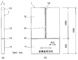
- FIG. 1 is a diagram showing the size and shape of a long ESSO test piece having a test piece width of 2400 mm.
- FIG. 2 is a diagram showing the size and shape of a large ESSO test piece having a test piece width of 1500 mm.
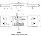
- FIG. 3 is a diagram showing a dynamic FEM analysis model (model 1) for investigating the influence of stress reflection on the evaluation of long brittle crack propagation stopping performance.
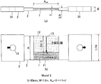
- FIG. 4 is a diagram showing a dynamic FEM analysis model (model 2) for investigating the influence of stress reflection on the evaluation of long brittle crack propagation stopping performance.
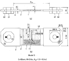
- FIG. 5 is a diagram showing a dynamic FEM analysis model (model 3) for investigating the influence of stress reflection on the evaluation of long brittle crack propagation stopping performance.
- FIG. 3 is a diagram showing a dynamic FEM analysis model (model 1) for investigating the influence of stress reflection on the evaluation of long brittle crack propagation stopping performance.
- FIG. 4 is a diagram showing a dynamic FEM analysis model (model 2) for investigating
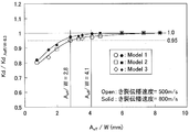
- FIG. 6 shows the results of analysis using the dynamic analysis model shown in FIGS. 3 to 5 and the test conditions (thickened part) on the dynamic stress intensity factor (Point C in FIGS. 3 to 5) when a test plate enters a long brittle crack.
- FIG. 3 is a diagram showing the influence of the thickness and the distance between the two.
- Kd is a dynamic stress intensity factor (dynamic stress intensity factor at Point C in FIGS. 3 to 5) when a long brittle crack enters the test plate
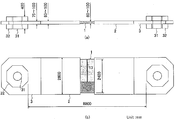
- FIG. 7 is a diagram showing the shapes of a test piece, a tab plate of a testing machine, and a pin chuck of the testing machine applied to the implementation of a long ESSO test.
- the present invention is for evaluating long brittle crack propagation stopping performance under conditions equivalent to an actual ship without stress reflection.
- a thickened portion that is 2.5 times or more the plate thickness t of the large test piece is provided in a large transmission portion for transmitting a tensile load from a tensile tester to a large ESSO test piece (also referred to as a large test piece). It is characterized in that it is provided with an interval that is at least 2.8 times the width W of the test piece, sandwiching the width center of the large test piece.
- the large specimen refers to the large specimen described in the Japan Maritime Association “Brittle Crack Arrest Design Guidelines” Annex B (2009).
- FIGS. show a large tensile test jig.
- 1 is a long ESSO test piece
- 11 is a test plate of the long ESSO test piece
- 12 is a crack-running plate of the long ESSO test piece
- 13 is a machined notch ( machined notch)
- 14 is electro-gas arc welding unit (welded part of electrogas arc welding)
- 15 is CO 2 arc welding unit (welded part of CO 2 arc welding )
- 2 test machine tab plates 3-pin tester
- the chuck, 31 is a pin hole of the testing machine
- 32 is a nut-shaped portion (thickening portion that reinforces the periphery of the pin hole)
- W is the width of a long ESSO test piece.
- the present invention is directed to a large test piece having a width W of 1.5 m or more. In general, the width W of the large test piece is 3 m or less.
- 1 and 2 show the shape of the long ESSO test piece 1 used in the analysis and the dimensions of each part.
- 1 is a welded portion 15 in which a test plate 11 and a run-up plate 12 are CO 2 arc welded along the rolling direction (RD) of the test plate 11. Hereinafter, they are joined by a CO 2 arc weld 15.
- the machined notch 13 is machined along the bond part of the electrogas arc welded part 14 of the run-up plate 12 in the middle of the welded part.
- a machined notch 13 is machined in the bond portion at the end of the electrogas arc welded portion 14 of the run-up plate 12, but the other configuration is the same as in FIG. 1.
- FIG. 3 to 5 show dynamic FEM analysis models.
- 3 and 5 are analysis models using the long ESSO test piece of FIG. 1
- FIG. 4 is an analysis model using the long ESSO test piece of FIG.
- the illustrated dynamic FEM analysis model is a parametric model for determining the condition without stress reflection, and is a model for analyzing the influence of the shape and dimensions of the transmission section.
- the transmission part is a part that transmits the tensile load from the tensile testing machine to the large test piece 1.
- the transmission portion refers to the center of the large-sized test piece 1 in the width-perpendicular direction (the position of the notch tip portion of the machined notch 13) at the end where the tensile load is applied on the large-sized test piece 1. In the left-right symmetry, it refers to a portion composed of the tab plate 2 of the testing machine and the pin chuck 3 of the testing machine.
- a portion where the thickness in the direction of the test piece plate thickness t in the transmission portion is 2.5 times or more of the test piece thickness t (plate thickness) is defined as a thickened portion.
- the width direction is a direction perpendicular to the rolling direction (RD) when the test plate is viewed from the plate thickness direction, and the width perpendicular direction is the rolling direction (RD). It is.
- the thickened portion of the transmission part is the pin chuck 3 of the test machine that is three times the test piece thickness t (plate thickness).
- the nut shape part (around the pin hole) of the pin chuck 3 of the testing machine Thickening portion that reinforces) 32.
- the upper limit of the thickness of the thickened portion is not particularly limited, but the thickness of the thickened portion is usually 20 times or less of the test piece thickness t (plate thickness).
- the tensile load from a tensile tester (not shown) is symmetrically loaded in the direction perpendicular to the width of the large test piece 1 by a pin (not shown) of the tensile tester inserted in the pin hole 31 of the thickened portion.
- the interval between the thickened portions (sometimes referred to as A eff ) is the shortest interval among the thickened portion intervals.
- the interval between the thickened portions is the interval (A eff in the figure) between the pin chucks 3 of the test machine, which is three times the thickness t (plate thickness) of the left and right test pieces.
- the distance between the tab plates 2 of the testing machine (A eff in the figure) that is 2.5 times the test piece thickness t (plate thickness) on the left and right In this case, the distance between the opposing surfaces of the nut-shaped portion 32 of the pin chuck 3 of the left and right test machines (A eff in the figure).
- FIG. 6 shows, as an analysis result, test conditions (thickness of the thickened portion and its interval (A eff )) that affect the dynamic stress intensity factor when entering the test plate 11 having a long crack (Point C in FIGS. 3 to 5). ).
- the dynamic stress intensity factor is the shape of the thickened portion around the pin hole 31 of the testing machine (the tab plate 2 of the testing machine, the pin chuck 3 of the testing machine, or the nut shape). It is reduced regardless of the shape of the portion 32. Then, when A eff is shorter than 2.8 times the specimen width W (when A eff / W is less than 2.8), the reduction becomes even more remarkable.
- a eff / W is set to 4.1 times or more, it becomes 97% or more of the test conditions where load reduction does not occur, and a more ideal test (more perfect test) becomes possible. If A eff / W is 6 times or more, the test condition is completely the same as the test condition in which no load drop occurs, and a more ideal test is possible.
- a eff is set to 2.8 times or more of the test piece width W, it is possible to evaluate the actual ship equivalent condition.
- the distance (A eff ) between the nut-shaped part (screw nut like part) 32 (thickness is 400 mm with respect to the plate thickness of 60 to 100 mm of the large test piece 1) shown in FIG. 7 is 8800 mm.
- the distance A eff of the thickened portion (loading tab plate of the testing machine or pin chuck of the testing machine) that loads / transmits the load is 2.8 times the test piece width or more, more preferably 4. More than 1 times. More ideally, it should be 6 times or more.
- test piece with a test piece width of 1.5 m or more under the above conditions, at the maximum allowable stress level (about 242 to 300 N / mm 2 ) of the ship, In order to evaluate the long brittle crack stopping performance without adding, it is necessary to set the load capacity of the testing machine to 50 MN or more.
- the test equipment that can evaluate the long-brittle crack propagation stopping performance under the conditions equivalent to an actual ship without stress reflection is the thickened part that loads / transmits the load (such as the tab plate of the testing machine or the pin chuck of the testing machine). ) Is more than 2.5 times the thickness of the specimen, and the distance between the thickened parts located at both ends of the specimen (shortest distance) is more than 2.8 times the specimen width. There is a device with a load capacity of 50MN or more.
- the load capacity of the testing machine When evaluating with a specimen width of 2m or more as described in the Japan Maritime Association's Guideline for Brittle Crack Arrest (Guidelines on Brittle Crack Arrest Design), the load capacity of the testing machine must be 80MN or more. . For this reason, it is more preferably a test apparatus having a load capacity of 80 MN or more.
- the upper limit value of the load capacity is not particularly limited, but the load capacity of the test apparatus is usually 100 MN or less.
- a thick steel plate having a thickness of 50 mm or more that can be stopped can be selected.
- the preferred component composition and preferred production conditions of this thick steel plate are as follows. In the description,% is mass%. Incidentally, a thick steel plate having a thickness of less than 50 mm can stop a long brittle crack with a current steel plate (for example, E-crass ship building steel).
- [Ingredient composition] C 0.15% or less C is necessary to ensure strength. From the viewpoint of ensuring strength, the lower limit of the C content is preferably 0.02%. However, if the C content exceeds 0.15%, the welded heat-affected zone (HAZ) toughness decreases, so the upper limit of the C content is limited to 0.15% or less. In order to further develop the texture of the (211) plane and the (100) plane, the C content is preferably 0.03% or less.
- Si 0.6% or less Si is an element effective for increasing the strength. In order to obtain the effect, the Si content is preferably 0.01% or more. When the amount of Si exceeds 0.6%, the weld heat affected zone (HAZ) toughness is significantly deteriorated. For this reason, the amount of Si was limited to 0.6% or less.
- HZ weld heat affected zone
- Mn 0.8 to 2.4%
- Mn is an element effective for increasing the strength. From the viewpoint of securing strength, the amount of Mn is set to 0.8% or more. However, if the amount of Mn exceeds 2.4%, there is a concern about deterioration of the toughness of base material. Therefore, the amount of Mn is set in the range of 0.8 to 2.4%. A preferable range of the amount of Mn is 1.0 to 1.7%.
- the S amount is set to 0.001% or more.
- S forms non-metal inclusions and deteriorates ductility and toughness. For this reason, the amount of S was made into 0.05% or less.
- Ti forms precipitates of carbides and nitrides This suppresses the growth of austenite grains in the heating stage during steel plate production and contributes to fine graining, and also suppresses the grain coarsening of the weld heat affected zone (HAZ) and improves the HAZ toughness. effective.
- HAZ weld heat affected zone
- the Ti content is 0.005% or more.
- Ti amount is made into 0.050% or less.
- Nb is also effective for precipitation strengthening and toughness improvement. Further, Nb suppresses recrystallization of austenite and promotes the effect due to rolling conditions described later. In order to obtain these effects, the Nb content is 0.001% or more. If the amount of Nb exceeds 0.1%, the hardened microstructure tends to be needle-like and the toughness tends to deteriorate. For this reason, the Nb content is 0.1% or less.
- Cu 2.0% or less, V: 0.2% or less, Ni: 2.0% or less, Cr: 0.6% or less, Mo: 0.6% or less, W: 0.5% or less, B: At least one selected from 0.0050% or less and Zr: 0.5% or less Cu: 2.0% or less Cu can be used mainly for precipitation strengthening.
- the Cu content is preferably 0.05% or more. If the amount of Cu exceeds 2.0%, precipitation strengthening becomes excessive and toughness deteriorates. For this reason, it is preferable to make Cu amount 2.0%.
- V 0.2% or less
- V is a component that can use solute strengthening and precipitation strengthening.
- the V amount is preferably 0.001% or more.
- the amount of V exceeds 0.2%, the toughness and weldability of the base metal are greatly impaired. For this reason, the V amount is preferably 0.2% or less.
- Ni 2.0% or less Ni improves strength and toughness. Ni is effective for preventing Cu cracking during rolling when Cu is added. In order to obtain the effect, the Ni content is preferably 0.05% or more. However, Ni is expensive and its effect is saturated even if Ni is added excessively. For this reason, the amount of Ni is preferably set to 2.0% or less.
- Cr 0.6% or less Cr has an effect of increasing strength.
- the Cr content is preferably 0.01% or more.
- the Cr content exceeds 0.6%, the toughness of the welded portion deteriorates. For this reason, it is preferable that the Cr content is 0.6% or less.
- Mo 0.6% or less Mo has an effect of increasing the strength at normal temperature and high temperature. In order to obtain the effect, the Mo amount is preferably 0.01% or more. However, if the Mo amount exceeds 0.6%, weldability deteriorates, so the Mo amount is preferably 0.6% or less.
- W 0.5% or less W has an effect of increasing the high-temperature strength.
- the W amount is preferably 0.05% or more.
- the W amount is preferably 0.5% or less.
- B 0.005% or less B precipitates as BN during rolling, and fines ferrite grains after rolling.
- the B content is preferably 0.001% or more.
- the amount of B exceeds 0.005%, the toughness deteriorates. For this reason, the amount of B was limited to 0.005% or less.
- Zr 0.5% or less
- Zr is an element that increases the strength and improves the plating cracking resistance of a galvanized material.
- the Zr content is preferably 0.03% or more.
- the amount of Zr exceeds 0.5%, the toughness of the welded portion deteriorates. For this reason, the amount of Zr is preferably 0.5% or less.
- the steel according to the present invention is the balance Fe and unavoidable impurities in addition to the above component composition.
- Inevitable impurities include P: 0.035% or less, Al: 0.08% or less, N: 0.012% or less, O: 0.05% or less, Mg: 0.01% or less, and the like. Acceptable.
- the temperature and cooling rate are average values in the thickness direction.
- Heating temperature The steel material is heated to a temperature of 900-1350 ° C.
- the heating temperature of 900 ° C. or higher is necessary for homogenization of the material and controlled rolling described later.
- the reason why the heating temperature is set to 1350 ° C. or lower is that when the temperature is excessively high, surface oxidation is remarkable and coarsening of crystal grains is unavoidable.
- the upper limit of the heating temperature is preferably 1150 ° C.
- rolling at a temperature exceeding 1000 ° C. promotes the growth of austenite grains, and thus is not preferable for refining.
- rolling at a temperature of less than 850 ° C. is not preferable for homogenizing the crystal grains because it is completely in the austenite non-recrystallization region at less than 850 ° C.
- the cumulative rolling reduction is less than 10%, it is not preferable because the austenite grains do not become sufficiently fine.
- the hot rolling is performed under the condition that the cumulative rolling reduction is 50% or more and the steel sheet surface temperature at the end of rolling is 800 to 550 ° C. This step introduces strain for making the transformed crystal grains fine.
- Rolling in the temperature range of 900 to 600 ° C. has the effect of refining crystal grains and developing a texture that is advantageous for arrestability.
- Table 2 shows the results of the long ESSO test.
- Nos. 2, 3, 5, 6, 8, 9, 12, and 14 are invention examples of the production method of the present invention, and a brittle crack is stopped at the test plate. For this reason, these can be evaluated as “good” by the evaluation method of the present invention.
- No. 1, 4, 7, 10, 11, 13, 15, 16 are comparative examples of the production method of the present invention, and the brittle crack did not stop. For this reason, these can be evaluated as “defective” by the evaluation method of the present invention.
- test plate 12 approach plate 13 machined notch 14 pin hole 32 nut-shaped portion of the pin chuck 31 tester of electro-gas arc welding unit 15 CO 2 arc welding unit 2 tester tab plate 3 Tester
Abstract
Description
(1)1.5m以上の幅を有する大型試験片の幅直角方向に引張試験機で引張荷重を負荷して、前記大型試験片におけるき裂長1m以上の長大脆性き裂に対する伝播停止性能を求める厚鋼板の長大脆性き裂伝播停止性能の評価方法であって、前記大型試験片に引張試験機からの引張荷重を伝達する伝達部が、前記大型試験片の厚さの2.5倍以上となる増厚部を、前記大型試験片の幅の2.8倍以上となる間隔で、前記大型試験片の幅直角方向の中心を挟んで有し、前記引張試験機からの引張荷重が、前記増厚部で前記大型試験片の幅直角方向の中心を挟んだ位置に負荷されることを特徴とする厚鋼板の長大脆性き裂伝播停止性能の評価方法。
(2)前記増厚部を前記大型試験片の幅の4.1倍以上となる間隔で有することを特徴とする(1)記載の厚鋼板の長大脆性き裂伝播停止性能の評価方法。
(3)1.5m以上の幅を有する大型試験片の幅直角方向に引張荷重を負荷して、前記大型試験片におけるき裂長1m以上の長大脆性き裂に対する伝播停止性能を求める厚鋼板の長大脆性き裂伝播停止性能を評価する装置であって、前記大型試験片に引張荷重を伝達する伝達部が、前記大型試験片の厚さの2.5倍以上となる増厚部を、前記大型試験片の幅の2.8倍以上となる間隔で、前記大型試験片の幅直角方向の中心を挟んで有し、前記引張荷重を、前記増厚部で前記大型試験片の幅直角方向の中心を挟んだ位置に負荷し、荷重容量(load capacity)が50MN(mega newton)以上であることを特徴とする厚鋼板の長大脆性き裂伝播停止性能を評価する装置。
(4)前記増厚部を前記大型試験片の幅の4.1倍以上となる間隔で有することを特徴とする(3)記載の厚鋼板の長大脆性き裂伝播停止性能を評価する装置。
(5)(3)または(4)に記載の装置において、前記荷重容量が80MN以上あることを特徴とする厚鋼板の長大脆性き裂伝播停止性能を評価する装置。
(6)(3)~(5)の何れか一つに記載の装置を用いて、厚鋼板の長大脆性き裂伝播停止性能を評価する工程を含むことを特徴とする長大脆性き裂伝播停止性能に優れる厚鋼板の製造方法。
(7)(6)に記載の厚鋼板の製造方法において、鋼組成が、質量%で、C:0.15%以下、Si:0.6%以下、Mn:0.8~2.4%、S:0.001~0.05%を含み、Ti:0.005~0.05%またはNb:0.001~0.1%の内から選んだ少なくとも1種を含み、更に、Cu:2%以下、V:0.2%以下、Ni:2%以下、Cr:0.6%以下、Mo:0.6%以下、W:0.5%以下、B:0.005%以下、Zr:0.5%以下の内から選んだ少なくとも1種を含有し、残部Feおよび不可避的不純物からなる鋼素材を、900~1350℃の温度に加熱し、次いで鋼板表面温度1000~850℃の温度域において累積圧下率(cumulative rolling reduction)10%以上圧延した後、鋼板表面温度900~600℃の温度域において累積圧下率50%以上で、圧延終了時の鋼板表面温度800~550℃で熱間圧延して製造することを特長とする長大脆性き裂伝播停止性能に優れる厚鋼板の製造方法。
(8)更に、熱間圧延を終了した後、5℃/s以上の冷却速度(cooling rate)で400℃まで冷却する(7)記載の長大脆性き裂伝播停止性能に優れる厚鋼板の製造方法。
(9)(6)~(8)の何れか一つに記載の製造方法により製造されることを特徴とする長大脆性き裂伝播停止性能に優れる厚鋼板。
C:0.15%以下
Cは強度を確保するために必要である。強度確保の観点からC量の下限を0.02%とするのが好ましい。しかし、C量が、0.15%を超えると溶接熱影響部(welded heat-affected zone)(HAZ)靭性が低下するので、C量の上限を0.15%以下に限定した。なお、(211)面および(100)面の集合組織をより一層発達させるために、C量は0.03%以下とすることが好ましい。
Siは強度上昇に有効な元素である。その効果を得るには、Siの含有量を0.01%以上とするのが好ましい。Si量が、0.6%を超えると溶接熱影響部(HAZ)靭性を著しく劣化させる。このため、Si量は0.6%以下に限定した。
Mnは高強度化に有効な元素である。強度確保の観点からMn量は0.8%以上とした。しかし、Mn量が2.4%を超えると、母材靭性(toughness of base material)の劣化が懸念される。したがって、Mn量は0.8~2.4%の範囲とした。なお、Mn量の好ましい範囲は1.0~1.7%である。
脆性き裂前縁にクラック(鋼板表面に平行な割れ)を発生させる必要があるため、S量は0.001%以上とする。しかし、Sは非金属介在物(non-metal inclusion)を形成し延性(ductility)および靭性を劣化させる。このためS量は0.05%以下とした。
Tiは、炭化物(carbide)や窒化物(nitride)の析出物(precipitate)を形成することにより、鋼板製造時の加熱段階でのオーステナイト粒(austenite grain)の成長を抑制して細粒化に寄与するとともに、溶接熱影響部(HAZ)の結晶粒粗大化も抑制しHAZ靱性を向上する効果がある。これらの効果を得るには、Ti量は0.005%以上とする。一方、Ti量が多すぎると、靱性が劣化する。このため、Ti量は0.050%以下とする。
Cu:2.0%以下
Cuは、主として析出強化のために用いることができる。その効果を得るには、Cu量は0.05%以上とするのが好ましい。Cu量が2.0%を超えると、析出強化が過多となり靱性が劣化する。このため、Cu量は2.0%とすることが好ましい。
Vは固溶強化(solute strengthening)と析出強化が利用できる成分である。その効果を得るには、V量は0.001%以上とするのが好ましい。V量が0.2%を超えると、母材の靭性および溶接性(weldability)を大きく損なう。このため、V量は0.2%以下とすることが好ましい。
Niは、強度および靱性を向上させる。また、Niは、Cuを添加した場合において、圧延時のCu割れを防止するのに有効である。その効果を得るには、Ni量は0.05%以上とするのが好ましい。しかし、Niは高価である上、Niを過剰に添加してもその効果が飽和する。このため、Ni量は2.0%以下とすることが好ましい。
Crは、強度を上昇させる効果を有する。その効果を得るには、Cr量は0.01%以上とするのが好ましい。しかし、Cr量が0.6%を超えると、溶接部の靱性が劣化する。このため、Cr量は0.6%以下とすることが好ましい。
Moは、常温および高温での強度を上昇させる効果を有する。その効果を得るには、Mo量は0.01%以上とするのが好ましい。しかし、Mo量が0.6%を超えると、溶接性が劣化するため、Mo量は0.6%以下とするのが好ましい。
Wは、高温強度を上昇させる効果を有している。その効果を得るには、W量は0.05%以上とするのが好ましい。しかし、W量が0.5%を超えると、靱性を劣化させるだけでなく、高価である。このため、W量は0.5%以下とするのが好ましい。
Bは圧延中にBNとして析出し、圧延後のフェライト粒(ferrite grain)を細かくする。その効果を得るには、B量は0.001%以上とするのが好ましい。しかし、B量が0.005%を超えると靱性が劣化する。このため、B量は0.005%以下に限定した。
Zrは、強度を上昇させるほか、亜鉛めっき材(galvanized material)の耐めっき割れ性(plating cracking resistance)を向上させる元素である。その効果を得るに、Zr量は0.03%以上とするのが好ましい。しかし、Zr量が0.5%を超えると、溶接部の靱性が劣化する。このため、Zr量は0.5%以下とするのが好ましい。
鋼素材は、900~1350℃の温度に加熱する。加熱温度を900℃以上とするのは、材質の均質化と後述する制御圧延(controlled rolling)を行うために必要である。また、加熱温度を1350℃以下とするのは、過度に高温になると表面酸化(surface oxidization)が顕著になるとともに、結晶粒(crystal grain)の粗大化(coarsening)が避けられなくなるからである。なお、靱性の向上のためには、加熱温度の上限を1150℃とすることが好ましい。
鋼板表面温度が1000~850℃の温度域において、累積圧下率が10%以上の条件で圧延する。この圧延によって、オーステナイト粒が部分的に再結晶するため、組織が微細かつ均一になる。
熱間圧延を終了した後、5℃/s以上の冷却速度で400℃まで冷却することが好ましい。400℃までの温度域を5℃/s以上の冷却速度で冷却すると、ベイナイトラス(bainite luth)が発達して、き裂の伝播抵抗(crack propagation resistance)となり、良好なアレスト性能(長大脆性き裂伝播停止性能)が得られる。


11試験板
12 助走板
13 機械加工ノッチ
14 エレクトロガスアーク溶接部
15 CO2アーク溶接部
2 試験機のタブ板
3 試験機のピンチャック
31 試験機のピン孔
32 ナット形状部
Claims (9)
- 1.5m以上の幅を有する大型試験片の幅直角方向に引張荷重を負荷して、前記大型試験片におけるき裂長1m以上の長大脆性き裂に対する伝播停止性能を評価する厚鋼板の長大脆性き裂伝播停止性能の評価方法であって、前記大型試験片に引張試験機からの引張荷重を伝達する伝達部が、前記大型試験片の厚さの2.5倍以上となる増厚部を、前記大型試験片の幅の2.8倍以上となる間隔で、前記大型試験片の幅直角方向の中心を挟んで有し、前記引張試験機からの引張荷重が、前記増厚部で前記大型試験片の幅直角方向の中心を挟んだ位置に負荷されることを特徴とする厚鋼板の長大脆性き裂伝播停止性能の評価方法。
- 前記増厚部を前記大型試験片の幅の4.1倍以上となる間隔で有することを特徴とする請求項1記載の厚鋼板の長大脆性き裂伝播停止性能の評価方法。
- 1.5m以上の幅を有する大型試験片の幅直角方向に引張荷重を負荷して、前記大型試験片におけるき裂長1m以上の長大脆性き裂に対する伝播停止性能を評価する厚鋼板の長大脆性き裂伝播停止性能を評価する試験装置であって、前記大型試験片に引張荷重を伝達する伝達部が、前記大型試験片の厚さの2.5倍以上となる増厚部を、前記大型試験片の幅の2.8倍以上となる間隔で、前記大型試験片の幅直角方向の中心を挟んで有し、前記引張荷重を、前記増厚部で前記大型試験片の幅直角方向の中心を挟んだ位置に負荷し、荷重容量が50MN以上であることを特徴とする厚鋼板の長大脆性き裂伝播停止性能を評価する試験装置。
- 前記増厚部を前記大型試験片の幅の4.1倍以上となる間隔で有することを特徴とする請求項3記載の厚鋼板の長大脆性き裂伝播停止性能を評価する試験装置。
- 前記荷重容量が80MN以上あることを特徴とする請求項3または4に記載の厚鋼板の長大脆性き裂伝播停止性能を評価する試験装置。
- 請求項3~5の何れか一つに記載の装置を用いて、厚鋼板の長大脆性き裂伝播停止性能を評価する工程を含むことを特徴とする長大脆性き裂伝播停止性能に優れる厚鋼板の製造方法。
- 請求項6の厚鋼板の製造方法において、鋼組成が、質量%で、C:0.15%以下、Si:0.6%以下、Mn:0.8~2.4%、S:0.001~0.05%を含み、Ti:0.005~0.05%またはNb:0.001~0.1%の内から選んだ少なくとも1種を含み、更に、Cu:2%以下、V:0.2%以下、Ni:2%以下、Cr:0.6%以下、Mo:0.6%以下、W:0.5%以下、B:0.005%以下、Zr:0.5%以下の内から選んだ少なくとも1種を含有し、残部Feおよび不可避的不純物からなる鋼素材を、900~1350℃の温度に加熱し、次いで鋼板表面温度1000~850℃の温度域において累積圧下率10%以上圧延した後、鋼板表面温度900~600℃の温度域において累積圧下率50%以上で、圧延終了時の鋼板表面温度800~550℃で熱間圧延して製造することを特長とする長大脆性き裂伝播停止性能に優れる厚鋼板の製造方法。
- 更に、熱間圧延を終了した後、5℃/s以上の冷却速度で400℃まで冷却する請求項7記載の長大脆性き裂伝播停止性能に優れる厚鋼板の製造方法。
- 請求項6~8の何れか一つに記載の製造方法により製造されることを特徴とする長大脆性き裂伝播停止性能に優れる厚鋼板。
Priority Applications (3)
| Application Number | Priority Date | Filing Date | Title |
|---|---|---|---|
| CN201380022478.8A CN104272084A (zh) | 2012-08-06 | 2013-08-02 | 厚钢板的长大脆性裂纹传播停止性能的评价方法、用于该评价方法的试验装置以及厚钢板的制造方法 |
| KR1020147026847A KR101728362B1 (ko) | 2012-08-06 | 2013-08-02 | 장대 취성 균열 전파 정지 성능이 우수한 후강판의 제조 방법 및 후강판 |
| JP2013542278A JPWO2014024445A1 (ja) | 2012-08-06 | 2013-08-02 | 厚鋼板の長大脆性き裂伝播停止性能の評価方法 |
Applications Claiming Priority (2)
| Application Number | Priority Date | Filing Date | Title |
|---|---|---|---|
| JP2012173940 | 2012-08-06 | ||
| JP2012-173940 | 2012-08-06 |
Publications (1)
| Publication Number | Publication Date |
|---|---|
| WO2014024445A1 true WO2014024445A1 (ja) | 2014-02-13 |
Family
ID=50067699
Family Applications (1)
| Application Number | Title | Priority Date | Filing Date |
|---|---|---|---|
| PCT/JP2013/004682 WO2014024445A1 (ja) | 2012-08-06 | 2013-08-02 | 厚鋼板の長大脆性き裂伝播停止性能の評価方法、それに用いる試験装置および厚鋼板の製造方法 |
Country Status (4)
| Country | Link |
|---|---|
| JP (2) | JPWO2014024445A1 (ja) |
| KR (1) | KR101728362B1 (ja) |
| CN (2) | CN107988471A (ja) |
| WO (1) | WO2014024445A1 (ja) |
Cited By (2)
| Publication number | Priority date | Publication date | Assignee | Title |
|---|---|---|---|---|
| CN110530105A (zh) * | 2019-08-28 | 2019-12-03 | 沈阳航空航天大学 | 一种用于低温拉伸过程的快速制冷装置 |
| CN112557131A (zh) * | 2019-09-10 | 2021-03-26 | 宝山钢铁股份有限公司 | 一种用于金属表面磨损拉毛分析与评价方法及其镶块 |
Families Citing this family (4)
| Publication number | Priority date | Publication date | Assignee | Title |
|---|---|---|---|---|
| CN105424474A (zh) * | 2015-11-03 | 2016-03-23 | 北京交通大学 | 一种评估钢结构厚板内部损伤累积的方法 |
| CN105734409A (zh) * | 2016-05-04 | 2016-07-06 | 芜湖市爱德运输机械有限公司 | 一种抗腐蚀提升机 |
| CN106018121B (zh) * | 2016-05-13 | 2019-06-04 | 攀钢集团研究院有限公司 | 一种厚度大于30mm焊接钢板弯曲试验方法 |
| WO2018216665A1 (ja) * | 2017-05-22 | 2018-11-29 | Jfeスチール株式会社 | 厚鋼板およびその製造方法 |
Citations (2)
| Publication number | Priority date | Publication date | Assignee | Title |
|---|---|---|---|---|
| JP2008156750A (ja) * | 2006-11-30 | 2008-07-10 | Jfe Steel Kk | 板厚方向の脆性亀裂伝播停止特性に優れる板厚50mm以上の鋼板およびその製造方法 |
| WO2012108543A1 (ja) * | 2011-02-08 | 2012-08-16 | Jfeスチール株式会社 | 長大脆性き裂伝播停止特性に優れる板厚50mm以上の厚鋼板およびその製造方法ならびに長大脆性き裂伝播停止性能を評価する方法および試験装置 |
Family Cites Families (7)
| Publication number | Priority date | Publication date | Assignee | Title |
|---|---|---|---|---|
| JPH0712692A (ja) * | 1993-06-25 | 1995-01-17 | Taisei Corp | 鋼板の板厚方向引張特性試験方法 |
| EP1312690B1 (en) * | 2001-11-14 | 2006-08-09 | Sumitomo Metal Industries, Ltd. | Steel material having improved fatigue crack driving resistance and manufacturing process therefor |
| JP5144053B2 (ja) * | 2006-05-12 | 2013-02-13 | Jfeスチール株式会社 | 脆性亀裂伝播停止特性に優れる溶接構造体 |
| JP4309946B2 (ja) * | 2007-03-05 | 2009-08-05 | 新日本製鐵株式会社 | 脆性き裂伝播停止特性に優れた厚手高強度鋼板およびその製造方法 |
| JP5337412B2 (ja) * | 2008-06-19 | 2013-11-06 | 株式会社神戸製鋼所 | 脆性亀裂伝播停止特性に優れた厚鋼板およびその製造方法 |
| JP4538094B2 (ja) * | 2008-09-17 | 2010-09-08 | 新日本製鐵株式会社 | 高強度厚鋼板およびその製造方法 |
| EP2508866B1 (en) * | 2010-03-04 | 2015-09-02 | Nippon Steel & Sumitomo Metal Corporation | Method for determination of brittle crack propagation stopping performance in high-intensity thick steel plate |
-
2013
- 2013-08-02 KR KR1020147026847A patent/KR101728362B1/ko active IP Right Grant
- 2013-08-02 WO PCT/JP2013/004682 patent/WO2014024445A1/ja active Application Filing
- 2013-08-02 JP JP2013542278A patent/JPWO2014024445A1/ja active Pending
- 2013-08-02 CN CN201711021061.6A patent/CN107988471A/zh active Pending
- 2013-08-02 CN CN201380022478.8A patent/CN104272084A/zh active Pending
-
2014
- 2014-09-01 JP JP2014176973A patent/JP6165116B2/ja active Active
Patent Citations (2)
| Publication number | Priority date | Publication date | Assignee | Title |
|---|---|---|---|---|
| JP2008156750A (ja) * | 2006-11-30 | 2008-07-10 | Jfe Steel Kk | 板厚方向の脆性亀裂伝播停止特性に優れる板厚50mm以上の鋼板およびその製造方法 |
| WO2012108543A1 (ja) * | 2011-02-08 | 2012-08-16 | Jfeスチール株式会社 | 長大脆性き裂伝播停止特性に優れる板厚50mm以上の厚鋼板およびその製造方法ならびに長大脆性き裂伝播停止性能を評価する方法および試験装置 |
Non-Patent Citations (2)
| Title |
|---|
| TOSHIYA AKIYAMA ET AL.: "A Study for the Evaluation of Brittle Crack Arrestability by the Wide Plate Duplex Esso Test", JOURNAL OF THE SOCIETY OF NAVAL ARCHITECTS OF JAPAN, 1983, pages 412 - 418 * |
| TSUNEHISA HANDA ET AL.: "Effect of Distance of Loading Points on Long Brittle Crack Propagation/Arrest Behavior", PROCEEDING OF THE NATIONAL SYMPOSIUM ON WELDING MECHANICS & DESIGN, vol. 2011, November 2011 (2011-11-01), pages 169 - 176 * |
Cited By (3)
| Publication number | Priority date | Publication date | Assignee | Title |
|---|---|---|---|---|
| CN110530105A (zh) * | 2019-08-28 | 2019-12-03 | 沈阳航空航天大学 | 一种用于低温拉伸过程的快速制冷装置 |
| CN112557131A (zh) * | 2019-09-10 | 2021-03-26 | 宝山钢铁股份有限公司 | 一种用于金属表面磨损拉毛分析与评价方法及其镶块 |
| CN112557131B (zh) * | 2019-09-10 | 2022-08-16 | 宝山钢铁股份有限公司 | 一种用于金属表面磨损拉毛分析与评价方法及其镶块 |
Also Published As
| Publication number | Publication date |
|---|---|
| CN107988471A (zh) | 2018-05-04 |
| KR20140127363A (ko) | 2014-11-03 |
| JP6165116B2 (ja) | 2017-07-19 |
| KR101728362B1 (ko) | 2017-04-19 |
| JP2015025205A (ja) | 2015-02-05 |
| JPWO2014024445A1 (ja) | 2016-07-25 |
| CN104272084A (zh) | 2015-01-07 |
Similar Documents
| Publication | Publication Date | Title |
|---|---|---|
| JP5598485B2 (ja) | 長大脆性き裂伝播停止特性に優れる板厚50mm以上の厚鋼板およびその製造方法 | |
| JP6165116B2 (ja) | 長大脆性き裂伝播停止性能に優れる厚鋼板の製造方法 | |
| WO2013150687A1 (ja) | アレスト性に優れた高強度厚鋼板 | |
| JP5598617B1 (ja) | 脆性亀裂伝播停止特性に優れた大入熱溶接用高強度厚鋼板およびその製造方法 | |
| JP5900312B2 (ja) | 大入熱溶接部の靭性および脆性き裂伝播停止特性に優れた高強度厚鋼板およびその製造方法 | |
| JP2010001520A (ja) | 脆性亀裂伝播停止特性に優れた厚鋼板およびその製造方法 | |
| TW201333219A (zh) | 脆性龜裂傳播停止特性優異之高強度厚鋼板及其製造方法 | |
| JP2018024905A (ja) | 脆性亀裂伝播停止特性に優れた構造用高強度厚鋼板およびその製造方法 | |
| Zhang et al. | Improving bonding quality of underwater friction stitch welds by selecting appropriate plug material and welding parameters and optimizing joint design | |
| JP5171327B2 (ja) | 大入熱溶接熱影響部の板厚方向靭性に優れたスキンプレート用鋼板およびその製造方法 | |
| JP5812193B2 (ja) | 脆性き裂伝播停止特性に優れた構造用高強度厚鋼板およびその製造方法 | |
| TWI504758B (zh) | High strength thick steel sheet and its manufacturing method with excellent brittle crack propagation characteristics | |
| JP6112265B2 (ja) | 高強度極厚鋼板およびその製造方法 | |
| Zhu et al. | Effect of deviation of welding parameters on mechanical properties of X80 steel girth weld | |
| Lee et al. | Effect of C-Mn ratio on the maximum hardness and toughness in TMCP steels with an identical carbon equivalent | |
| Ichiyama et al. | Factors affecting flash weldability in high strength steel–a study on toughness improvement of flash welded joints in high strength steel | |
| JP5838801B2 (ja) | 厚鋼板及び厚鋼板の製造方法 | |
| JP2017160537A (ja) | 脆性き裂伝播停止特性および溶接熱影響部靭性に優れた高強度極厚鋼板およびその製造方法 | |
| WO2018030171A1 (ja) | 高強度厚鋼板およびその製造方法 | |
| WO2017145651A1 (ja) | 脆性き裂伝播停止特性に優れた高強度極厚鋼板およびその製造方法 | |
| JP2010077494A (ja) | 大入熱溶接用鋼材 | |
| Takahashi et al. | Metallurgical approaches for product development and process optimization | |
| Cicholska | The weldability assessment of thermally hardened S540Q steel sheets | |
| Hsieh et al. | The mechanism of the formation of boron ineffective zone and its effect on the properties of Ultralow carbon bainitic steels |
Legal Events
| Date | Code | Title | Description |
|---|---|---|---|
| ENP | Entry into the national phase |
Ref document number: 2013542278 Country of ref document: JP Kind code of ref document: A |
|
| 121 | Ep: the epo has been informed by wipo that ep was designated in this application |
Ref document number: 13827921 Country of ref document: EP Kind code of ref document: A1 |
|
| ENP | Entry into the national phase |
Ref document number: 20147026847 Country of ref document: KR Kind code of ref document: A |
|
| NENP | Non-entry into the national phase |
Ref country code: DE |
|
| 122 | Ep: pct application non-entry in european phase |
Ref document number: 13827921 Country of ref document: EP Kind code of ref document: A1 |